Abstract
The power spectral density (PSD) shape of the transmit waveform plays an important role in some fields of radar, such as electronic counter-countermeasures (ECCM), target detection, and target classification. In addition, radar hardware generally requires the waveform to have constant modulus (CM) characteristics. Therefore, it is a significant problem to synthesize the discrete-time CM waveform from a given PSD. To address this problem, some algorithms have been proposed in the existing literature. In this paper, based on the majorization–minimization (MM) framework, a novel algorithm is proposed to solve this problem. The proposed algorithm can be proved to converge to the stationary point, and the error reduction property can be obtained without the unitary requirements on the discrete Fourier transform (DFT) matrix. To accelerate the convergence rate of the proposed algorithm, three acceleration schemes are developed for the proposed algorithm. Considering a specific algorithm stopping condition, one of the proposed acceleration schemes shows better computation efficiency than the existing algorithms and is more robust to the initial points. Besides, when the DFT matrix is not unitary, the numerical results show that the proposed acceleration scheme has better matching performance compared with the existing algorithms.
1. Introduction
Optimizing the power spectral density (PSD) of the transmit waveform to improve the system performance has always been an important topic in radar. The design of waveform PSD has been widely studied in many fields of radar. In electronic counter-countermeasures (ECCM), the strategy of radar and jammer is a spectrally designed waveform [,,,,,,]. In target detection, the PSD of a waveform is optimized for different detecting environments and targets [,,,,]. In refs. [,,,,,,,,], the PSD is designed to maximize the mutual information or Mahalanobis distance for target classification.
It should be noticed that most of the above works only obtained an optimal PSD template, rather than a transmit waveform that can be directly used by the radar. In radar system, constant modulus (CM) constraint ensures that the radio frequency amplifiers work with maximum efficiency and avoids signal distortion [,]. Many methods have been proposed to produce CM waveform for transmit beampattern matching [,,] or thinned spectrum design [,,]. The thinned spectrum is commonly used to avoid occupied frequency bands to prevent interference between multiple systems [,,,]. However, in scenarios involving target detection, target classification, or ECCM, the frequency responses of targets and the environment are uncertain, and the optimal PSD shape is uncertain. Consequently, there is a need to generate CM waveforms with arbitrary desired PSD shapes. For arbitrary PSD shape matching, the alternating projections method was proposed in refs. [,] to synthesize the CM waveform. However, the success of this kind of method is still unexplained. In ref. [], from the view of phase retrieval, the authors explained the success of alternating projections by relating them to the error reduction algorithm (ERA). However, the error reduction property (ERP) can only be obtained when the discrete Fourier transform (DFT) matrix satisfies the left or right unitary requirements.
For the requirements of arbitrary PSD shape matching, motivated by the limitations in existing CM waveform synthesis methods, a novel algorithm based on the majorization–minimization (MM) framework is proposed in this paper. The main contributions of this paper can be summarized as follows:
- Based on the MM framework, a novel algorithm is proposed to obtain a CM waveform that matches an arbitrary PSD template. Compared with existing algorithms, the ERP of the proposed algorithm can be proved without the unitary requirements of the DFT matrix. Besides, the proposed algorithm can be proved to converge to the stationary point.
- Three acceleration schemes are developed to accelerate the convergence speed of the proposed algorithm. All the acceleration versions keep the ERP. Numerical results show that one of the acceleration schemes has better computational efficiency than the existing algorithms and is more robust to the initial points than existing algorithms.
- Because without the unitary requirements of DFT matrix, compared with existing algorithms, one of the proposed acceleration schemes shows the better matching performance when DFT matrix is not unitary and the code length is less than the number of frequency points. Besides, this difference becomes apparent for complex PSD shapes.
The remainder of this paper is structured as follows. The problem formulation and proposed new algorithms are detailed in Section 2. Section 3 presents the computational findings, and a discussion about the algorithm’s performance under another PSD template is presented in Section 4. Conclusions are draw in Section 5.
Notation: We adopt standard case letters for scalars, bold uppercase letters for matrices, and bold lowercase letters for vectors. The operator notations , , and represent matrix transpose, element-wise conjugation, and Hermitian transposition, respectively. See Table 1 for other notations used throughout this paper.

Table 1.
Notations.
2. Materials and Methods
It is assumed that the baseband signal of radar is , where is the pulse duration. The baseband signal can be sampled as , where is the sampling period and L denotes the code length. Let denote the transmit waveform, and the DFT of can be given by
where is the DFT matrix, and N is the number of the interesting frequencies [].
Suppose that the desired PSD is . In order to match the given PSD, we have the following cost function:
The constraint in (2) guarantees the CM property. is called the Fourier transform magnitude in ref. []. Under the CM constraint, the waveform can be denoted as , where is the phase of . Then, the cost function (2) can be converted into an equivalent form as follows:
where
In general, the problem (3) lacks an analytical solution. Previous works have obtained the iteration solution efficiently; however, they lack a theoretical explanation or place restrictions on the DFT matrix. From the view of MM, the ERP can be obtained easily, and the proposed algorithm can converge to the stationary point. In this section, we first introduce the ERP of the MM method. Additional details regarding MM are available in refs. [,].
2.1. MM Method
As a problem-driven approach, the MM method demonstrates remarkable computational efficiency in practical applications. The key idea of MM is to construct a simple surrogate function that yields an algorithm with low computational complexity.
Consider the following optimization problem
Following the idea of MM, we first find the constructed surrogate function for , which should meet these requirements at :
The MM update rule can be expressed as
2.2. MM-Based Matching Algorithm
Let denote the objective function of (3), and in order to construct the surrogate function of , we introduce the following lemma:
Lemma 1
(Descent Lemma []). Let be a continuously differentiable function with a Lipschitz continuous gradient and Lipschitz constant . Then, for all ,
Therefore, in order to construct the surrogate function, we have the following lemma to characterize the Lipschitz properties of . The detailed proof of Lemma 2 is in Appendix B.
Lemma 2.
Gradient is Lipschitz continuous, i.e.,
where the detailed calculation of the constant μ refers to Appendix B.
Combining Lemmas 1 and 2, we can construct the surrogate function of as follows:
Notice that the function is a strongly convex quadratic function with respect to . Therefore, the optimal solution of problem (12) is given by
where the computation of gradient is shown in Appendix A.
2.3. Convergence Analysis
With the theoretical analysis of (3) now complete, we summarize the entire MM-based matching algorithm (MMA) in pseudocode format in Algorithm 1. In the following, we prove that the sequence generated by MMA converges to a stationary point.
| Algorithm 1 MMA—MM-based Matching Algorithm |
|
Lemma 3.
The sequence generated by MMA converges to a stationary point of problem (3).
2.4. Acceleration Schemes
From Appendix B and Appendix C, it is noticed that the surrogate function might be relatively loose as an upperbound of . Consequently, the convergence rate is relatively slow. In this subsection, an acceleration scheme is proposed for MMA to improve the convergence rate. The idea of this acceleration scheme is to find a tighter upperbound for the original objective function at each iteration. It is assumed that the value of changes with the iteration. From Lemmas 1 and 2, we know that there is at the ℓ-th iteration, which satisfies the following inequality:
Therefore, the surrogate function at the ℓ-th iteration can be constructed as
Similar to MMA, the point of the next iteration can be obtained by
It is noticed that, in this way, if the inequality (14) holds, the ERP of MM is still satisfied. Plugging (16) into (14), we have
then
Inequality (17) guarantees the ERP of the proposed algorithm, and it shows that a smaller means a faster convergence rate. Combining (17) and (18), we adopt such an acceleration scheme: use a line search method to find a small that satisfies the inequality (17). The complete description of acceleration MMA (AMMA) is given in Algorithm 2. Our numerical results suggest that AMMA can achieve a superlinear convergence rate.
| Algorithm 2 AMMA—Acceleration MMA |
|
The SQUAREM can be easily implemented as an off-the-shelf accelerator for the MM algorithm. For more details about SQUAREM, readers can refer to []. Compared with other acceleration schemes, it has two important advantages: first, it only requires an MM variable updating scheme; second, it is guaranteed to converge. It is noticed that both MMA and AMMA obey the MM updating scheme. Therefore, we utilize SQUAREM to accelerate MMA and AMMA to further improve the convergence rate. They are noted as A-MMA-S and A-AMMA-S, respectively.
Let and denote the maps of the MMA and AMMA algorithms, respectively. The MM updating scheme of MMA and AMMA can be expressed as and , respectively. For brevity, both the details of A-MMA-S and A-AMMA-S are shown in Algorithm 3.
| Algorithm 3 A-MMA-S—Accelerating MMA by SQUAREM and A-AMMA-S—Accelerating AMMA by SQUAREM |
|
2.5. Complexity Analysis and Implementation Platform
We now analyze the computational complexity of the proposed algorithms. The overall complexity of each algorithm is linear with respect to the number of iterations. For the convenience of analysis, we focus on the deterministic cost on a per-iteration basis. For MMA, the main computational cost lies in computing . According to Appendix A, the cost to obtain is roughly .
For AMMA, the main computational cost lies in computing and . The cost to obtain is roughly complex multiplications. Combined with the computational cost of , we can see that the total cost of AMMA is roughly , where is the iteration number of the line search part of AMMA. From simulation experience, the average number of is about 9 when . For A-MMA-S and A-AMMA-S, the cost of each iteration is nearly twice as much as MMA and AMMA, respectively. Assume that the iteration number of line search part in SQUAREM is (the line search part is to ensure the feasible solution and the ERP of MM, which has also been used in refs. [,]). Consequently, the total cost of A-MMA-S is roughly , and the total cost of A-AMMA-S is roughly
From simulation experience, the average number of is about 2 when . When , the average number of and is generally much smaller. According to [], the computational complexity of ERA is roughly .
All proposed algorithms can be executed in Matlab software under Windows environment. Specifically, the results shown below are obtained using Matlab R2017b.
3. Results
In this section, we conduct numerical simulations to evaluate the proposed algorithms for the desired PSD matching. The desired PSD (i.e., ) is taken from ref. [], which is used for ECCM and with a bandwidth of 10 MHz. Because the gradient of objective function has been obtained, we also apply the classical conjugate gradient (CG) method to solve problem (3). Finally, the ERA and CG methods are adopted as comparison algorithms. In all the following simulations, the algorithms are run 1000 times for each case, with each trial corresponding to a new random phase initialization. All algorithms are given the same initialization at the beginning of each trial. To evaluate the average performance of each algorithm, we normalize the value of at each iteration over all trials as follows:
Considering the influence of the DFT matrix property on the algorithms, we adopt the DFT matrices that satisfy the left or right unitary requirements and those that do not satisfy the left or right unitary requirements in the following simulations, respectively. Specifically, consider the following four scenarios:
(1) Case 1: () and ;
(2) Case 2: () and ;
(3) Case 3: () and ;
(4) Case 4: () and .
The specific expressions of the adopted DFT matrices are shown in Appendix D.
In practical application, the reasonable stopping criterion is used to measure how close a point is to the optimal solution or suboptimal solution to stop the algorithm. Considering the ERP of each algorithm, the following stopping criterion is adopted for each algorithm:
It should be noted that considering the influence of initial points on convergence performance, the maximum iteration number is set to 50,000 for all algorithms in the following simulations.
The following simulation experiments are divided into two parts. The first part shows the performance of the proposed algorithm and the acceleration effect of the proposed acceleration schemes. The second part compares the matching performance and computational efficiency between the proposed acceleration schemes and existing algorithms.
3.1. The Performance of Proposed Algorithms
In this subsection, we show the performance of the proposed algorithm and acceleration schemes. First, we consider the scenario . In Figure 1, an example solution of each algorithm under Case 1 is shown. It can be seen that all algorithms can match the desired PSD template and can keep the ERP. However, it can be noticed that the acceleration schemes have better matching performance, which may be caused by MMA reaching the maximum iteration number rather than the stopping criterion. For the convergence rate, it can be observed that the proposed acceleration schemes have a significant effect. In Figure 2, we show the box plot result of all 1000 random trials under Case 1. It can be seen that the acceleration schemes have similar matching performance and are better than MMA. From a statistical perspective, all acceleration schemes have better convergence performance than MMA, and A-MMA-S has the best convergence performance and is less sensitive to the initial points. In Figure 3 and Figure 4, we show an example solution under Case 2 and the box plot result of all 1000 random trials under Case 2, respectively. It can be seen that all algorithms perform similarly to Case 1. However, it can be noticed that compared with Case 1, each algorithm in Case 2 has a slower convergence rate but better matching performance.
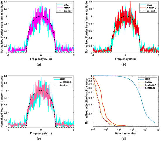
Figure 1.
An example solution of proposed algorithms under Case 1: (a) The result of MMA and AMMA. (b) The result of MMA and A-MMA-S. (c) The result of MMA and A-AMMA-S. (d) The convergence curve of all algorithms.
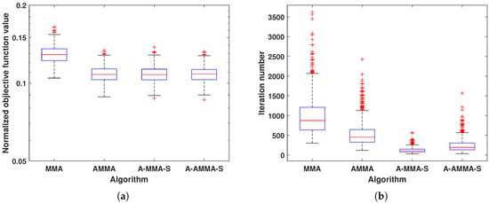
Figure 2.
The box plot result of proposed algorithms under Case 1: (a) Normalized objective function value. (b) Iteration number.
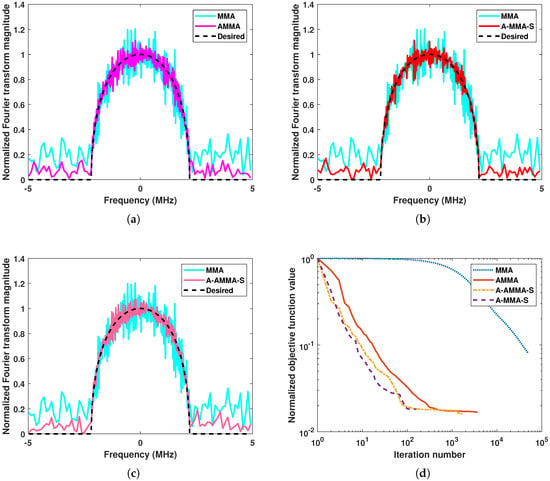
Figure 3.
An example solution of proposed algorithms under Case 2: (a) The result of MMA and AMMA. (b) The result of MMA and A-MMA-S. (c) The result of MMA and A-AMMA-S. (d) The convergence curve of all algorithms.
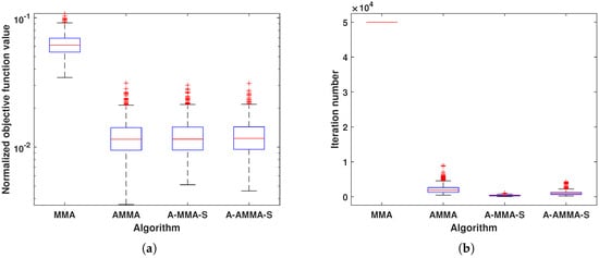
Figure 4.
The box plot result of proposed algorithms under Case 2: (a) Normalized objective function value. (b) Iteration number.
Then, we consider the scenario . In Figure 5 and Figure 6, we show an example solution under Case 3 and the box plot result of all 1000 random trials under Case 3, respectively. Similarly, the results under Case 4 are shown in Figure 7 and Figure 8, respectively. It can be observed that all algorithms perform similarly to Case 1. Ignoring the CM constraint, the original problem (2) is an underdetermined equation when . Therefore, it can be noticed that compared with Case 1 and Case 2, each algorithm in Case 3 and Case 4 has a faster convergence rate and better matching performance.
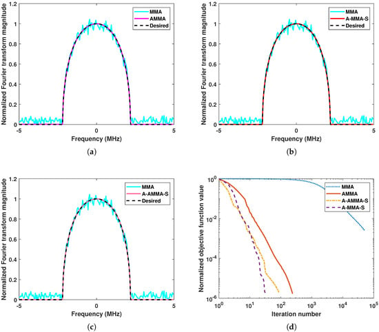
Figure 5.
An example solution of proposed algorithms under Case 3: (a) The result of MMA and AMMA. (b) The result of MMA and A-MMA-S. (c) The result of MMA and A-AMMA-S. (d) The convergence curve of all algorithms.
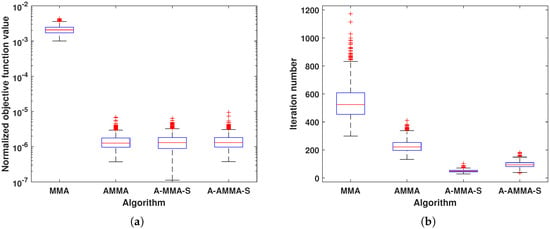
Figure 6.
The box plot result of proposed algorithms under Case 3: (a) Normalized objective function value. (b) Iteration number.
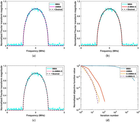
Figure 7.
An example solution of proposed algorithms under Case 4: (a) The result of MMA and AMMA. (b) The result of MMA and A-MMA-S. (c) The result of MMA and A-AMMA-S. (d) The convergence curve of all algorithms.
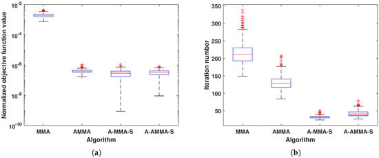
Figure 8.
The box plot result of proposed algorithms under Case 4: (a) Normalized objective function value. (b) Iteration number.
3.2. Algorithm Comparison
In this subsection, we compare the matching performance and computational time of the proposed algorithm with algorithms CG and ERA. From Section 3.1, it can be noticed that A-MMA-S has the best computational efficiency. Therefore, for the sake of simplicity, we will only compare A-MMA-S with other algorithms. Figure 9 shows an example solution and the corresponding computational time of each algorithm under Case 1. It can be noticed that the matching performance of each algorithm is similar, but A-MMA-S has a significantly shorter computation time. The statistical results in Figure 10 also confirm the above phenomenon. Figure 11 and Figure 12 show the results of each algorithm under Case 2. It can be seen that ERA has significantly worse matching performance and computational efficiency than other algorithms, which may be due to the fact that the DFT matrix is not a unitary matrix in Case 2. From a statistical perspective, it can be observed in Figure 12 that the proposed A-MMA-S has the best matching performance and computational efficiency.

Figure 9.
The comparison between algorithms under Case 1: (a) The example solution of A-MMA-S and CG. (b) The example solution of A-MMA-S and ERA. (c) Normalized objective function value versus computational time.
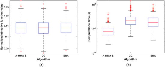
Figure 10.
The box plot result comparison under Case 1: (a) Normalized objective function value. (b) Computational time.

Figure 11.
The comparison between algorithms under Case 2: (a) The example solution of A-MMA-S and CG. (b) The example solution of A-MMA-S and ERA. (c) Normalized objective function value versus computational time.
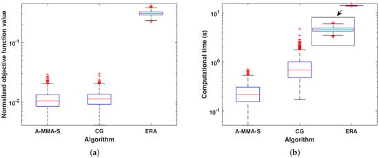
Figure 12.
The box plot result comparison under Case 2: (a) Normalized objective function value. (b) Computational time.
For the scenario , the results are shown in Figure 13, Figure 14, Figure 15 and Figure 16. In Figure 13 and Figure 14, we show the results of each algorithm under Case 3. It can be seen that all algorithms can have good matching performance, and CG is slightly better than the other two algorithms. For the computational time, the proposed algorithm A-MMA-S has the best performance, but CG is significantly inferior to other algorithms. In Figure 15 and Figure 16, we show the results of each algorithm under Case 4. It can be seen that the matching performance of each algorithm is similar. In Case 4, ERA can match the desired PSD well when the DFT matrix is not unitary, which may be due to the fact that the original problem is underdetermined when . It can be observed from Figure 16b that A-MMA-S still has the best computational efficiency.

Figure 13.
The comparison between algorithms under Case 3: (a) The example solution of A-MMA-S and CG. (b) The example solution of A-MMA-S and ERA. (c) Normalized objective function value versus computational time.
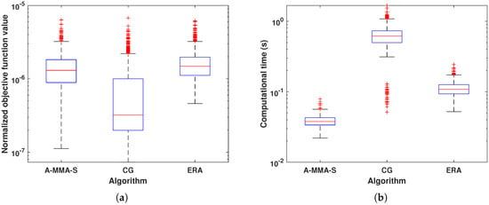
Figure 14.
The box plot result comparison under Case 3: (a) Normalized objective function value. (b) Computational time.

Figure 15.
The comparison between algorithms under Case 4: (a) The example solution of A-MMA-S and CG. (b) The example solution of A-MMA-S and ERA. (c) Normalized objective function value versus computational time.
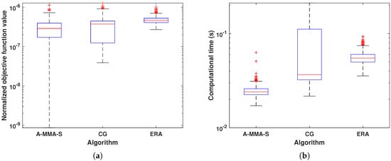
Figure 16.
The box plot result comparison under Case 4: (a) Normalized objective function value. (b) Computational time.
Overall, for all considered scenarios, the proposed algorithm A-MMA-S has the shortest computational time. Besides, from the statistical results, it can be found that the computational time performance of A-MMA-S is most robust to the initial points. For the matching performance, except for Case 3, the proposed algorithm A-MMA-S has the best performance. In Case 3, the matching error has been reduced to the magnitude of . Therefore, the difference between A-MMA-S and CG is actually negligible. Specifically, in Case 2, where and the DFT matrix is not unitary, the matching performance of A-MMA-S is significantly better than that of ERA and slightly better than CG.
4. Discussion: Algorithm Performance Under Another PSD Template
The adopted PSD template in Section 3 is used in the ECCM scene, and its shape is simple and regular. In order to comprehensively measure the performance of algorithms, the PSD shape in [] is used as the template in this section. This PSD shape is applied in target detection and is more complex and irregular. From the results in Section 3.2, it can be found that compared with other cases, Case 2 is more challenging. Therefore, only the simulation results under Case 2 are shown in this section.
In Figure 17 and Figure 18, we show the results of the proposed algorithm and acceleration schemes. It can be found that the behavior of each algorithm is similar to that in Figure 3 and Figure 4. In Figure 19 and Figure 20, we compare the results of A-MMA-S, CG, and ERA. From Figure 19, it can be found that the matching performance of the proposed algorithm is much better than that of CG and ERA. Especially, the ERP of ERA can no longer be held. The statistical results in Figure 20 also confirm the matching performance of the proposed algorithm, and it can be seen that the high computational efficiency of the proposed algorithm still holds. Comparing the results in Figure 11 and Figure 19, it can be found that the proposed algorithm has better performance in complex and irregular PSD matching.
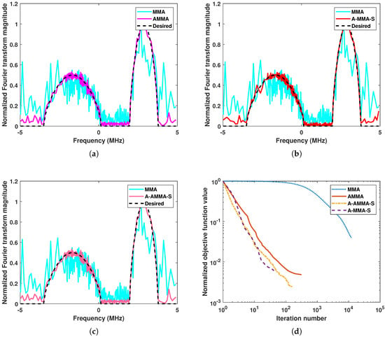
Figure 17.
An example solution of proposed algorithms under another PSD template: (a) The result of MMA and AMMA. (b) The result of MMA and A-MMA-S. (c) The result of MMA and A-AMMA-S. (d) The convergence curve of all algorithms.
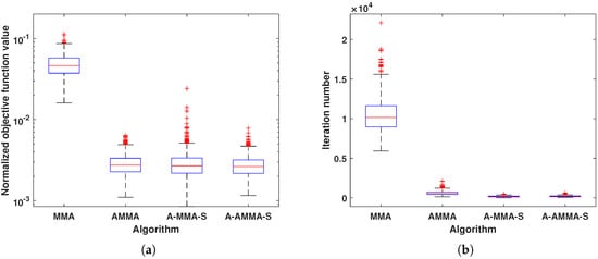
Figure 18.
The box plot result of proposed algorithms under another PSD template: (a) Normalized objective function value. (b) Iteration number.

Figure 19.
The comparison between algorithms under another PSD template: (a) The example solution of A-MMA-S and CG. (b) The example solution of A-MMA-S and ERA. (c) Normalized objective function value versus computational time.
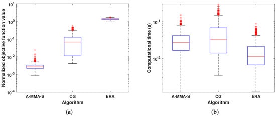
Figure 20.
The box plot result comparison under another PSD template: (a) Normalized objective function value. (b) Computational time.
5. Conclusions
Motivated by the need for radar waveforms with the desired PSD, we propose an algorithm to synthesize the discrete-time CM signals from the given PSD. Based on the MM framework, the proposed algorithm has the ERP and can be proved to converge to the stationary point. To realize a trade-off between convergence rate and computation complexity, three acceleration versions of the proposed algorithm are also given. Numerical results show that the acceleration version A-MMA-S has better computation efficiency and competitive matching performance compared with the existing algorithms.
Author Contributions
Conceptualization, H.Z.; methodology, H.Z.; software, H.Z.; validation, H.Z.; investigation, H.Z.; writing original draft preparation, H.Z. and J.Y.; writing—review and editing, H.Z., C.Q., and C.L.; supervision, H.Z. and J.Y. All authors have read and agreed to the published version of the manuscript.
Funding
This work was supported by the Natural Science Foundation of Inner Mongolia Autonomous Region of China under Grants 2023QN06003 and 2021JQ07, the National Natural Science Foundation of China under Grants 62461047, 62361046 and 62371264, the Young Talents of Science and Technology in Universities of Inner Mongolia Autonomous Region under Grant NJYT22109, the Training Plan for Young Innovative of Grassland Talents Project in Inner Mongolia Autonomous Region under Grant Q2022003, the Innovation Capability Support Program of Shaanxi under Grant 2023KJXX-015 and the Science and Technology Project of Henan Province under Grant 252102210246.
Data Availability Statement
The original contributions presented in the study are included in the article; further inquiries can be directed to the corresponding author.
Conflicts of Interest
The authors declare no conflicts of interest.
Appendix A. The Computation of ∇hω
Let , and we have
For , we have
Therefore, we can get that
Appendix B. Proof of Lemma 2
In the following, we prove that is Lipschitz continuous via the definition of Lipschitz continuity. For , we have the following derivations:
According to Lagrange’s mean value theorem, because is continuous and differentiable, there exists some point between and , which satisfies
In order to state clearly, we rewrite
and we have
where the last equality follows from the CM property of .
According (A11), we have
In Appendix C, we give the upperbound of the right side of inequality (A15). Therefore, we can obtain the upperbound of , and we have
Appendix C. The Upperbound Derivations
The upperbound of :
The expression of can refer to Appendix A, and we have
The modulus of elements in is , where , so we have
Finally, we have
The upperbound of :
Let . According to the structures of , we can find that for all ,
Therefore,
where denotes the maximum eigenvalue of a matrix. For the maximum singular value of , we have
Besides,
where R denotes the rank number of and .
Therefore, we have
The upperbound of :
For all , we have
Therefore, and are positive semidefinite Hermitian matrices.
According the structures of , we get that for all ,
and we have
From (A27), we can find that the diagonal elements of are nonnegative; therefore,
Finally,
Appendix D. The DFT Matrices Used in Simulations
Let denote the (l-th, n-th) element of , and it is written as
where is a sequence contains interesting frequencies. In the following, the in different cases is given.
Case 1:
and
where
and the same below.
Case 2:
and
Case 3:
and
Case 4: and
References
- Li, K.; Jiu, B.; Liu, H. Game Theoretic Strategies Design for Monostatic Radar and Jammer Based on Mutual Information. IEEE Access 2019, 7, 72257–72266. [Google Scholar] [CrossRef]
- Song, X.; Willett, P.; Zhou, S.; Luh, P.B. The MIMO Radar and Jammer Games. IEEE Trans. Signal Process. 2012, 60, 687–699. [Google Scholar] [CrossRef]
- Lan, X.; Li, W.; Wang, X.; Yan, J.; Jiang, M. MIMO Radar and Target Stackelberg Game in the Presence of Clutter. IEEE Sens. J. 2015, 15, 6912–6920. [Google Scholar] [CrossRef]
- Xin, F.; Wang, Y.; Sun, J.; Huang, Y. Adaptable waveform design for radar and jammer for multi-target using game theoretic strategies. EURASIP J. Adv. Signal Process. 2022, 2022, 99. [Google Scholar] [CrossRef]
- Ding, W.; Zhang, W.; Zhang, M.; Wang, Q.; Shao, G.; Zhou, J. Networked radar waveform design for detecting extended target in the presence of jamming. Phys. Commun. 2025, 68, 102539. [Google Scholar] [CrossRef]
- Xu, Z.; Tang, B.; Ai, W.; Zhu, J. Relative entropy based jamming signal design against radar target detection. IEEE Trans. Signal Process. 2025, 73, 1200–1215. [Google Scholar] [CrossRef]
- Wang, L.; Zhang, Y. The monostatic radar and jammer games based on signal-to-jamming-plus-noise ratio. IEEE Access 2022, 10, 15023–15035. [Google Scholar] [CrossRef]
- Kay, S. Optimal Signal Design for Detection of Gaussian Point Targets in Stationary Gaussian Clutter/Reverberation. IEEE J. Sel. Top. Signal Process. 2007, 1, 31–41. [Google Scholar] [CrossRef]
- Zhu, Z.; Kay, S.; Raghavan, R.S. Locally Optimal Radar Waveform Design for Detecting Doubly Spread Targets in Colored Noise. IEEE Signal Process. Lett. 2018, 25, 833–837. [Google Scholar] [CrossRef]
- Zhu, Z.; Kay, S.; Raghavan, R.S. Information-Theoretic Optimal Radar Waveform Design. IEEE Signal Process. Lett. 2017, 24, 274–278. [Google Scholar] [CrossRef]
- Wu, J.; Zhang, J.; Chen, Y. Constrained Pulse Radar Waveform Design Based on Optimization Theory. Sensors 2025, 25, 1203. [Google Scholar] [CrossRef] [PubMed]
- Xin, F.; Li, J.; Wang, Y.; Zhang, M. SINR-and MI-Based Double-Robust Waveform Design. Entropy 2022, 24, 1841. [Google Scholar] [CrossRef] [PubMed]
- Kim, H.; Goodman, N.A.; Lee, C.K.; Yang, S. Improved waveform design for radar target classification. Electron. Lett. 2017, 53, 879–881. [Google Scholar] [CrossRef]
- Garren, D.A.; Odom, A.C.; Osborn, M.K.; Goldstein, J.S.; Pillai, S.U.; Guerci, J.R. Full-polarization matched-illumination for target detection and identification. IEEE Trans. Aerosp. Electron. Syst. 2002, 38, 824–837. [Google Scholar] [CrossRef]
- Garren, D.A.; Osborn, M.K.; Odom, A.C.; Goldstein, J.S.; Pillai, S.U.; Guerci, J.R. Enhanced target detection and identification via optimised radar transmission pulse shape. IEE Proc. Radar Sonar Navig. 2001, 148, 130–138. [Google Scholar] [CrossRef]
- Xin, F.; Wang, B.; Li, S.; Song, X.; Wang, C.H. Adaptive radar waveform design based on weighted MI and the difference of two mutual information metrics. Complexity 2021, 2021, 8947450. [Google Scholar] [CrossRef]
- Wu, Z.J.; Wang, C.X.; Li, Y.C.; Zhou, Z.Q. Extended target estimation and recognition based on multimodel approach and waveform diversity for cognitive radar. IEEE Trans. Geosci. Remote Sens. 2021, 60, 5101014. [Google Scholar] [CrossRef]
- Alshirah, S.Z.; Gishkori, S.; Mulgrew, B. Optimal target classification using frequency-based radar waveform design. IEEE Trans. Geosci. Remote Sens. 2021, 60, 4703409. [Google Scholar] [CrossRef]
- Warnke, M.; Brüggenwirth, S. Waveform adaptation for target classification using hrrp in a cognitive framework. IEEE Trans. Aerosp. Electron. Syst. 2022, 59, 3695–3712. [Google Scholar] [CrossRef]
- Yu, R.; Luo, C.; Bai, M.; Yang, W.; Fu, Y. Waveform Design using Cauchy-Schwarz Divergence for Target Detection. IEEE Signal Process. Lett. 2025, 32, 1710–1714. [Google Scholar] [CrossRef]
- Idriss, Z.; Raj, R.G.; Narayanan, R.M. Waveform optimization for multistatic radar imaging using mutual information. IEEE Trans. Aerosp. Electron. Syst. 2021, 57, 2410–2425. [Google Scholar] [CrossRef]
- Zhao, L.; Palomar, D.P. Maximin Joint Optimization of Transmitting Code and Receiving Filter in Radar and Communications. IEEE Trans. Signal Process. 2017, 65, 850–863. [Google Scholar] [CrossRef]
- Stoica, P.; Li, J.; Zhu, X. Waveform Synthesis for Diversity-Based Transmit Beampattern Design. IEEE Trans. Signal Process. 2008, 56, 2593–2598. [Google Scholar] [CrossRef]
- Yu, X.; Cui, G.; Yang, J.; Kong, L. Wideband MIMO radar beampattern shaping with space-frequency nulling. Signal Process. 2019, 160, 80–87. [Google Scholar] [CrossRef]
- Aldayel, O.; Monga, V.; Rangaswamy, M. Tractable Transmit MIMO Beampattern Design Under a Constant Modulus Constraint. IEEE Trans. Signal Process. 2017, 65, 2588–2599. [Google Scholar] [CrossRef]
- Zhao, Z.; Palomar, D.P. MIMO Transmit Beampattern Matching Under Waveform Constraints. In Proceedings of the 2018 IEEE International Conference on Acoustics, Speech and Signal Processing (ICASSP), Calgary, AB, Canada, 15–20 April 2018; pp. 3281–3285. [Google Scholar]
- Kassab, R.; Lesturgie, M.; Fiorina, J. Alternate projections technique for radar waveform design. In Proceedings of the 2009 International Radar Conference “Surveillance for a Safer World” (RADAR 2009), Bordeaux, France, 12–16 October 2009; pp. 1–4. [Google Scholar]
- Patton, L.K.; Bryant, C.A.; Himed, B. Radar-centric design of waveforms with disjoint spectral support. In Proceedings of the 2012 IEEE Radar Conference, Atlanta, GA, USA, 7–11 May 2012; pp. 0269–0274. [Google Scholar] [CrossRef]
- Zhao, Y.N.; Li, F.C.; Zhang, T.; Zhou, Z.Q. Computational design of optimal waveforms for MIMO radar via multi-dimensional iterative spectral approximation. Multidimens. Syst. Signal Process. 2016, 27, 43–60. [Google Scholar] [CrossRef]
- Alaee-Kerahroodi, M.; Raei, E.; Kumar, S.; Rao, B.S.M.R. Coexistence of communications and cognitive MIMO radar: Waveform design and prototype. arXiv 2021, arXiv:2103.11890. [Google Scholar]
- Alaee-Kerahroodi, M.; Raei, E.; Kumar, S.; MRR, B.S. Cognitive radar waveform design and prototype for coexistence with communications. IEEE Sens. J. 2022, 22, 9787–9802. [Google Scholar] [CrossRef]
- Aubry, A.; De Maio, A.; Govoni, M.A.; Martino, L. On the design of multi-spectrally constrained constant modulus radar signals. IEEE Trans. Signal Process. 2020, 68, 2231–2243. [Google Scholar] [CrossRef]
- He, J.; Huang, W.; Cheng, Z.; Li, H.; Hea, Z. Joint Design of OFDM Sequences and Mismatch Filter under Spectral Constraints. In Proceedings of the 2023 IEEE Radar Conference (RadarConf23), Sydney, Australia, 6–10 November 2023; pp. 1–4. [Google Scholar]
- Pillai, S.U.; Li, K.Y.; Beyer, H. Reconstruction of constant envelope signals with given Fourier transform magnitude. In Proceedings of the 2009 IEEE Radar Conference, Pasadena, CA, USA, 4–8 May 2009; pp. 1–4. [Google Scholar] [CrossRef]
- Patton, L.K.; Rigling, B.D. Phase Retrieval for Radar Waveform Optimization. IEEE Trans. Aerosp. Electron. Syst. 2012, 48, 3287–3302. [Google Scholar] [CrossRef]
- Ying, S.; Babu, P.; Palomar, D.P. Majorization-Minimization Algorithms in Signal Processing, Communications, and Machine Learning. IEEE Trans. Signal Process. 2016, 65, 794–816. [Google Scholar]
- Hunter, D.R.; Lange, K. A tutorial on MM algorithms. Am. Stat. 2004, 58, 30–37. [Google Scholar] [CrossRef]
- Bertsekas, D. Nonlinear Programming; Athena Sci: Belmont, MA, USA, 1999. [Google Scholar]
- Razaviyayn, M.; Hong, M.; Luo, Z.Q. A Unified Convergence Analysis of Block Successive Minimization Methods for Nonsmooth Optimization. Siam J. Optim. 2012, 23, 1126–1153. [Google Scholar] [CrossRef]
- Varadhan, R.; Roland, C. Simple and Globally Convergent Methods for Accelerating the Convergence of Any EM Algorithm. Scand. J. Stat. 2010, 35, 335–353. [Google Scholar] [CrossRef]
- Wu, L.; Babu, P.; Palomar, D.P. Cognitive Radar-Based Sequence Design via SINR Maximization. IEEE Trans. Signal Process. 2017, 65, 779–793. [Google Scholar] [CrossRef]
- Song, J.; Babu, P.; Palomar, D.P. Sequence Design to Minimize the Weighted Integrated and Peak Sidelobe Levels. IEEE Trans. Signal Process. 2016, 64, 2051–2064. [Google Scholar] [CrossRef]
Disclaimer/Publisher’s Note: The statements, opinions and data contained in all publications are solely those of the individual author(s) and contributor(s) and not of MDPI and/or the editor(s). MDPI and/or the editor(s) disclaim responsibility for any injury to people or property resulting from any ideas, methods, instructions or products referred to in the content. |
© 2025 by the authors. Licensee MDPI, Basel, Switzerland. This article is an open access article distributed under the terms and conditions of the Creative Commons Attribution (CC BY) license (https://creativecommons.org/licenses/by/4.0/).