Article

Modified Morphological Component Analysis Method for SAR Image Clutter Suppression

by
Shuangying Xiao
1,
Huaping Xu
1,
Bing Sun
1,* and
Wei Liu
2
1
School of Electronic and Information Engineering, Beihang University, Beijing 100191, China
2
Department of Electrical and Electronic Engineering, The Hong Kong Polytechnic University, Kowloon, Hong Kong
*
Author to whom correspondence should be addressed.
Remote Sens. 2025, 17(10), 1727; https://doi.org/10.3390/rs17101727
Submission received: 20 March 2025 / Revised: 30 April 2025 / Accepted: 13 May 2025 / Published: 15 May 2025

Abstract

:
The morphological component analysis (MCA) method can be used to suppress the clutter in a synthetic aperture radar (SAR) image when the dictionaries of clutter and target components are mutually incoherent. However, the effectiveness of the conventional MCA method may be reduced since the mutual incoherence assumption is difficult to fulfill in practice. To overcome the problem, a modified MCA method is proposed in this paper. The proposed method formulates clutter suppression as a constraint optimization problem that combines MCA with incoherence constraint and L 0 gradient minimization, and it presents an effective solution to the optimization problem. Specifically, the incoherence constraint of image components is designed to decorrelate different components and better separate targets from clutter. Meanwhile, the L 0 gradient minimization constraint is applied to further reduce the artifacts and preserve edges. Then, the optimization problem of the modified MCA is split into solvable subproblems to obtain the target image. Finally, experimental results from real images are carried out to demonstrate the effectiveness of the proposed clutter suppression method.

1. Introduction

Synthetic aperture radar (SAR) can acquire high-resolution microwave images all day and all weather, and SAR images have been widely applied in land investigation, ocean surveillance, military reconnaissance, etc. [1,2]. In SAR images, the clutter can be considered as the backscattering coefficient of the observation scene that the observer is not interested in, and the target of interest is usually surrounded by background clutter. For example, ships and ship wakes are often surrounded by sea clutter, and buildings and cars are often surrounded by ground clutter. The strong clutter can cover small and weak targets, obscure target edge contour, and affect the effective extraction of target features, which has a great impact on the subsequent SAR image processing. Therefore, it is necessary to perform clutter suppression on SAR images to eliminate clutter interference in targets, obtain more accurate target features, and improve the accuracy and efficiency of subsequent target detection, classification, and recognition.
Many clutter suppression methods have been developed over the years, including the displaced phase center antenna (DPCA) [3] and space-time adaptive processing (STAP) [4], but these multichannel methods are typically used to suppress the clutter in moving targets. The spatial-domain filtering methods of despeckling can be used to suppress clutter [5] represented by the Lee [6] and Frost [7] and median filters [8]. These methods perform averaging or statistically manipulate the pixel values of the image, but they may weaken the edge and point features due to the use of neighboring pixel values. Clutter suppression can also be achieved by using transform-domain filtering methods, such as wavelet and block-matching and 3D-filtering (BM3D) filters [9,10]. These transform-domain filtering methods usually suppress the clutter by thresholding the transform-domain coefficients, but artifacts may be introduced into the image due to the variation of the coefficients. The subspace-based methods, including singular value decomposition (SVD) [11] and principal component analysis (PCA) [12], assume that target and clutter lie in different subspaces and suppress clutter by removing clutter subspaces, but precise measurement of the clutter subspace is required for high performance [13]. With the rapid development of deep learning, many deep learning algorithms have been applied to clutter suppression areas, including the convolutional neural network (CNN) [14] and generative adversarial network (GAN) [15]. But a large amount of training data and computing resources are needed to train these networks.
Morphological component analysis (MCA) is an image decomposition method based on sparse representation [16], where the image is split into cartoon parts and texture parts. Applying the MCA method to SAR images for clutter suppression, by taking the cartoon part as the target component and the texture part as the clutter component, has also attracted the attention of researchers [17,18,19]. Based on the advantages of sparse representation and morphological diversity, MCA can effectively suppress clutter [17,20]. As introduced in [17], the MCA method is used to remove the clutter in ground-penetrating radar (GPR) images, where the un-decimated discrete wavelet transform (UDWT) dictionary and the curvelet dictionary are used to differentiate the landmine target and clutter components. In [18], a local discrete cosine transform is used to represent clutter, and the un-decimated wavelet transform is used to represent the target, and the resultant target image after clutter suppression is shown to improve the generalization capability of the automatic target recognition (ATR) system. In [19], using the block coordinate descent (BCD) dictionary learning method to construct the ship wake and the sea background texture dictionaries, the ship wake is effectively separated from the sea background by the MCA method.
The key to clutter suppression with MCA is to choose appropriate dictionaries to distinguish different components. If the dictionaries are mutually incoherent and the target and clutter components can only be sparsely represented by their corresponding dictionaries, the target component will be well separated from the clutter after solving the MCA optimization problem. However, in practice, it is difficult to fully realize the mutual incoherence between different dictionaries, which means that the same morphological component may be sparsely represented by different dictionaries; as a result, the separated target and clutter components become correlated, hindering the decomposition of SAR images by the MCA method. In addition, the separated target component inevitably suffers from artifacts, since each component is sparsely reconstructed from the corresponding dictionary in the MCA decomposition.
To address the above problem, a modified MCA method is proposed to enhance the incoherence between different components and improve the image decomposition result. The optimization problem for modified MCA integrates the incoherence constraint and L 0 gradient minimization. In detail, the incoherence constraint of images is designed to remove the similarity components between different image components; then, the proposed incoherence constraint is added to the conventional MCA model to guide the target separation from background clutter in SAR images. Meanwhile, L 0 gradient minimization [21] is introduced to preserve target structures while eliminating artifacts generated during MCA decomposition. The resultant nonconvex optimization problem is solved by iteratively solving multiple subproblems. Note that the proposed incoherence constraint is independent of the selected dictionaries and intrinsic to the separated image components. Thus, it can be applied to the MCA with any selected dictionary and has the advantages of directness and universality. As demonstrated by experimental results on real images with both qualitative and quantitative evaluations, a better clutter suppression performance has been achieved by the proposed method.
The remainder of this paper is organized as follows. Section 2 introduces the proposed modified MCA method. In Section 3, experimental results with detailed analysis are presented. In Section 4, a discussion of the proposed method is presented. Finally, conclusions are drawn in Section 5.

2. Methodology

In this section, the existing MCA-based clutter suppression methods for SAR images are first introduced. Then, an incoherence constraint method of images is proposed to enhance the separation ability of the MCA method. Finally, the incoherence constraint and L 0 gradient minimization are incorporated into the MCA objective function to develop a modified MCA method. The proposed modified MCA method not only encourages different components to be uncorrelated by the incoherence constraint but also smooths homogeneous areas and preserves salient structures by L 0 gradient minimization. It unifies separation, smoothing, and edge preservation in the clutter suppression process.

2.1. Existing MCA-Based SAR Image Clutter Suppression Method

The existing MCA-based clutter suppression method is based on the assumption that the SAR image is a linear mixture of clutter and target components. An appropriate dictionary is selected to achieve the sparse representation of each component, then the SAR image is decomposed, and the reconstructed target component can be regarded as the result of clutter suppression. Based on the assumption, an SAR image X can be expressed as the sum of the target component X t , the clutter component X c , and noise n [19], as follows:
X = X t + X c + n .
Dictionaries D t and D c are supposed to provide efficient sparse representations of X t and X c , respectively, while representing the other is inefficient. α t and α c are the sparse coefficients corresponding to X t and X c under their respective dictionaries, that is, X t = D t α t and X c = D c α c . Equation (1) can be rewritten as follows:
X = X t + X c + n = D t α t + D c α c + n .
To seek the sparsest representation of X t and X c , α t and α c can be solved by the following constrained optimization problem:
arg min α t , α c α t 0 + α c 0 s . t . X D t α t D c α c 2 ϵ .
Equation (3) is nonconvex, and by replacing the L 0 norm with the L 1 norm and the constrained optimization with the unconstrained penalized optimization, Equation (3) becomes the following [22]:
arg min α t , α c α t 1 + α c 1 + λ X D t α t D c α c 2 2 ,
where α t 1 and α c 1 are sparsity terms, X D t α t D c α c 2 2 is the reconstruction error, and λ is the regularization parameter that controls the tradeoff between reconstruction error and sparsity.
During the MCA decomposition process, to recover piecewise smooth objects with pronounced edges and remove noisy artifacts, the total variation (TV) regularization is applied to the target component, and the resulting minimization task becomes the following [16]:
arg min α t , α c α t 1 + α c 1 + λ X D t α t D c α c 2 2 + ξ T V ( D t α t ) .
The specific steps of the MCA decomposition algorithm can be found in [16]. After obtaining α t and α c , X t = D t α t can be obtained as the SAR image after clutter suppression.
The existing MCA-based clutter suppression method can separate the target from the clutter under the condition of mutual incoherence of the dictionaries, which makes certain that the sparsity of different components in the same dictionary is mutually exclusive. However, in practice, it is difficult to guarantee mutual incoherence between the selected dictionaries. As a result, the separated target and clutter components may share some common characteristics, leading to degradation in clutter suppression performance.

2.2. Optimization Problem of the Proposed Method

The existing MCA-based clutter suppression methods mainly divide SAR images into target components and clutter components based on the sparse representation of dictionaries. As mentioned, mutual incoherence of the dictionaries is a key assumption of MCA decomposition. The main types of dictionaries include fixed dictionaries based on specific mathematical transformations and learned dictionaries based on adaptive learning. In practice, different types of dictionaries can be selected and used in combination according to the specifics of each component. However, when using a combination of fixed dictionaries, both dictionaries can represent the same component if there is an evident overlap between the functional transformations [16]. When using the combination of learned dictionaries, some dictionary atoms may be shared between different learned dictionaries [23], and the coherence between the dictionary atoms is not conducive to image component separation. Similarly, the combination of fixed and learned dictionaries may also struggle in maintaining incoherence since it is difficult to ensure mutual incoherence at each update of the learned dictionary.
To resolve the problem of unsatisfactory image component separation caused by the coherence of selected dictionaries, the incoherence constraint is proposed and added to the MCA model. When the incoherence constraint directly acts on the dictionaries, dictionary incoherence has to be achieved by increasing the incoherence of dictionary atoms at the dictionary update stage, which requires that the learned dictionary must be included in the MCA model. Since the learned dictionary is an overcomplete matrix, the computational cost of dictionary updates and decorrelation operations is high. Moreover, the incoherence constraint of dictionaries also limits the applicability of the MCA model because fixed dictionary combinations that cannot be updated are excluded by the dictionary update requirement. Since the ultimate goal of MCA decomposition is to obtain incoherent target components and clutter components, the incoherence constraint of images is proposed to minimize the degree of similarity between images. The incoherence constraint of images can be applied to the clutter and target components under any selected dictionaries in the modified MCA method, realizing MCA decomposition effectively and conveniently.

2.2.1. Incoherence Constraint of Images

Inspired by the mutual incoherence of random orthogonal bases in [24], the absolute inner product between two unitized signals is used to measure the similarity between different signals. Normalizing the original signal can obtain a unitized vector:
t = t 0 t 0 2 ,
where t 0 is the original signal, and t is the unitized signal.
The similarity between different signals is defined as follows:
g = t i , t j = t i T t j , i j ,
where t i R N and t j R N are two different unitized signals, and g [ 0 , 1 ] . When the value of g is closer to 1, it means that the similarity between signals is high; conversely, signals are mutually incoherent when g is equal to 0. So, g represents the degree of coherence between any pair of signal components, and g = 0 is an ideal incoherence constraint.
If the signal t i has similar components to signal t j , the similarity between signals can be reduced by using the incoherence constraint. The specific objective function is defined as follows:
arg min t t t i 2 2 s . t . t j T t 2 = 0 ,
where t represents the output of the signal t i after incoherent processing. Equation (8) can be transformed into a general unconstrained form, seeking a balance between reconstruction error and incoherence constraint, and rewritten as follows:
F ( t ) = arg min t t t i 2 2 + η t j T t 2 ,
where η is an incoherence parameter directly controlling the level of incoherence between signals. One of the most popular approaches for solving this objective function (9) is the gradient descent (GD) method [25], which uses the following iterative scheme:
t k + 1 = t k μ F ( t k ) ,
where k is the iteration number, μ is the step size, and F ( t k ) is the gradient of the cost function, which can be calculated as follows:
F ( t k ) = F ( t k ) / t k = t k t i + η t j t j T t k .
Therefore, the solution of Equation (11) can be updated by the following equation:
t k + 1 = t k + μ t i η t j t j T t k .
The proposed incoherence constraint is based on the one-dimensional (1D) unitized signal. Since directly performing incoherent processing on the 1D vectors generated by large-size two-dimensional (2D) images requires a lot of memory and powerful computing resources, a block-based operation is applied to subdivide the large image into smaller image blocks, and then the blocks are processed independently using incoherence constraints.
Since the same component may only exist in the local positions of two large-size images, that is, the similarities between different image blocks are different, it is necessary to perform incoherent processing on the image blocks adaptively. The incoherence effect between image blocks is controlled by the incoherence parameter. As the value of the incoherence parameter increases, the incoherence constraint between signals is enhanced. Therefore, the incoherence between image blocks can be controlled by adjusting the value of the incoherence parameter. An incoherence parameter setting method based on the logistic function is proposed:
η ( g ) = δ 1 + e β ( g γ ) .
The logistic function is an S-shaped function of similarity g, with the range 0 to δ . The parameter δ > 0 determines the maximum value of the incoherence parameter, while the parameters γ and β determine the center and steepness of the logistic function, respectively. The parameter γ is responsible for distinguishing the coherent and incoherent components of the image, with a range of 0 < γ < 1 . The parameter β controls the transition rate between the coherent and incoherent components, with a range of β > 0 . Different logistic parameter values determine different degrees of image incoherent processing, which can be selected by experience and specific experimental results. With the determined logistic parameters δ , β , and γ , the incoherence parameters of image blocks of the 2D images are calculated by their similarity g and logistic function (13).
The proposed incoherence constraint works on the image in the following way: First, the two coherent images are divided into blocks of equal size and overlap, and each image block is reduced to a 1D unitized vector; then the incoherence parameter of each group of blocks is calculated, and the GD method is used to solve the incoherence constraint result. Finally, the same operation is performed on all image blocks, and the final incoherent image result is reconstructed by taking the weighted average of all incoherent image blocks. The procedure of the incoherence constraint algorithm is summarized in Algorithm 1.
Algorithm 1: The Incoherence Constraint Algorithm.
  • Input: image X 1 and the coherent image X 2
  • Initialization: the number of iterations K and the parameters μ , δ , β and γ .
  • Divide X 1 and X 2 into N rectangular blocks of equal size and
  • equal overlap: { x 1 1 , x 1 2 , , x 1 n , , x 1 N } and { x 2 1 , x 2 2 , , x 2 n , , x 2 N } .
  • For n = 1 to N
  •     Normalize the n-th blocks of the two images into 1D unitized vectors:
  • t i = x 1 n / | | x 1 n | | 2 , t j = x 2 n / | | x 2 n | | 2
  •     Calculate the similarity of unitized vectors: g = t i T t j
  •     Calculate the incoherence parameter: η = δ / ( 1 + e β ( g γ ) )
  •     For k = 1 to K
  •         Update variable: t k + 1 = t k + μ ( t i η t j t j T t k )
  •     End
  •     Recover image block: x ^ 1 n = t K · | | x 1 n | | 2
  • End
  • Reconstruct 2D image X ^ 1 from the blocks { x ^ 1 1 , x ^ 1 2 , , x ^ 1 n , , x ^ 1 N }
  • Output: Incoherent image X ^ 1

2.2.2. Modified MCA Method

By imposing the incoherence constraint between images, the similarity between two image components can be effectively reduced. When using the MCA method to decompose SAR images, the separated target and clutter images will inevitably contain the same components due to the influence of the coherent dictionary. Therefore, introducing the incoherence constraint in the MCA method can reduce the similarity between the target and clutter components.
The optimization problem of the conventional MCA method is shown in Equation (4), which consists of sparsity terms and a data fidelity term. Since the incoherence constraint of the dictionaries is only applicable to part of the dictionaries and has high complexity, adding the incoherence constraint of target and clutter components in MCA can effectively improve the results of image decomposition. The corresponding optimization problem of MCA with incoherence constraint is proposed:
arg min α t , α c α t 1 + α c 1 + λ X D t α t D c α c 2 2 + η D c α c T ( D t α t ) 2 ,
where D c α c T ( D t α t ) 2 is the incoherence constraint term for target component X t and clutter component X c , and the incoherence parameter η can be determined by the logistic function (13), controlling the incoherence between clutter and target components.
The proposed MCA method with incoherence constraint can successfully separate target and clutter components, but it relies on sparse reconstruction of dictionaries, which will introduce artifacts that often degrade the quality of reconstructed images. To reduce artifacts, the main idea is to impose some constraints on the optimization problem, and TV regularization is widely adopted in MCA [16]. Although TV regularization has the advantages of edge preservation and denoising, it sometimes produces an undesirable staircase effect in the image’s flat areas [26]. Therefore, to balance homogeneous areas smoothing and edge structure preservation, L 0 gradient minimization is employed in this paper, which can enhance edge contrast by confining the number of nonzero gradients and smooth the image in a global manner [21].
Assuming the reconstruction result of the target component is S , the gradient of each pixel p in the x and y directions is S ( p ) = S ( p ) / x , S ( p ) / y T , and then the gradient measure of target component can be denoted as follows [21]:
L ( S ) = # { p | | S ( p ) / x | + S ( p ) / y 0 } ,
where # { } is the counting operator, calculating the number of p whose gradient magnitude | S ( p ) / x | + S ( p ) / y is nonzero, that is, the L 0 norm of the gradient. The structure edges can be preserved by constraining the number of nonzero gradients with L ( S ) κ while smoothing the image, where κ is a constant. Since the image gradient in target regions is more prominent than that of artifacts, L 0 gradient minimization can effectively smooth the images and preserve important structural information. Because there are no pronounced edge structures in the clutter component, it is only utilized on the target component to eliminate artifacts and avoid edge blurring.
Adding the L 0 gradient minimization constraint to the target component in Equation (15), a modified MCA method is developed, which combines the incoherence constraint and L 0 gradient minimization to achieve better image component separation while improving the quality of the separated target components. The final proposed formulation is given as follows:
arg min α t , α c α t 1 + α c 1 + λ X D t α t D c α c 2 2 + η D c α c T ( D t α t ) 2 + ξ L ( D t α t ) ,
where, L ( D t α t ) is the L 0 regularization term of the target component, and the parameter ξ > 0 is a positive real number controlling the smoothness of the target image components.
Obviously, by solving the problem (16), the mutually incoherent target and clutter components can be obtained from the SAR image while preserving structure edges and eliminating artifacts in target components.

2.3. Solution to Optimization Problem

Since the modified MCA optimization problem (16) is to solve the sparse coefficients of the target and clutter components, the final desired target component can be obtained from the sparse coefficients through sparse representation. Therefore, Equation (16) can be transformed to the image domain, with the benefit of reducing the dimensionality of the problem:
arg min X t , X c D t + X t 1 + D c + X c 1 + λ X X t X c 2 2 + η X c T X t 2 + ξ L ( X t ) ,
where D t + and D c + are the Moore–Penrose pseudoinverse of dictionaries D t and D c respectively. Before solving the modified MCA optimization problem, a set of regularization parameters is required to provide a tradeoff between multiple objectives of sparsity, reconstruction error, incoherence constraint, and L 0 gradient minimization. Since the optimization function of the modified MCA is complicated, it is difficult to derive a simple adaptive parameter selection method in specific applications. In this paper, by utilizing experimental results and prior knowledge of regularization parameters, their values are adjusted empirically to optimize the modified MCA to reach satisfactory results.
Since the problem in Equation (17) is a multivariate nonconvex function and difficult to solve directly, the proximal gradient method is used to formulate the optimization problem as the following minimization problem:
arg min X t , X c { C ( X t , X c ) + D ( X t ) } ,
where
C ( X t , X c ) = D t + X t 1 + D c + X c 1 + λ X X t X c 2 2 + η X c T X t 2 ,
D ( X t ) = L ( X t ) ,
C ( X t , X c ) is the MCA decomposition with an incoherence constraint, which is used to effectively separate the target and clutter components. D ( X t ) is the L 0 gradient minimization constraint, which is used to preserve the edge structure of the target component and eliminate artifacts.
The ADMM method is employed here to solve the multivariate optimization problem (19), where the objective function is split into a series of subproblems, and a single variable is optimized in each iteration while keeping the other variables fixed. Accordingly, combined with L 0 gradient minimization, the modified MCA can be achieved by solving the following subproblems successively, where the superscript m ( m = 0 , 1 , 2 , M ) represents the iteration index:
X t ( m + 1 ) = arg min X t C ( X t , X c ( m ) ) ,
X c ( m + 1 ) = arg min X c C ( X t ( m + 1 ) , X c ) ,
X t ( m + 1 ) = arg min X t L ( X t ( m + 1 ) ) .
The variables X t , X c are updated alternately, and each iteration calculation uses the result from the previous iteration. The iterative process can be divided into two steps: image components update and L 0 gradient minimization.

2.3.1. Updating Image Components

By dropping the unrelated terms, the optimization subproblem to update image components can be formulated as follows:
X t ( m + 1 ) = arg min X t D t + X t 1 + λ X X t X c ( m ) 2 2 + η X c ( m ) T X t 2 ,
X c ( m + 1 ) = arg min X c D c + X c 1 + λ X X t ( m + 1 ) X c 2 2 + η X c T X t ( m + 1 ) 2 .
These L 1 norm minimization problems in Equations (24) and (25) can be solved by the iterative shrinkage-thresholding algorithm (ISTA) [27], and the solutions are given by the following:
X t ( m + 1 ) = D t s o f t σ ( m + 1 ) ( D t + ( X t ( m ) + λ R ( m ) η ( X c ( m ) ) ( X c ( m ) ) T X t ( m ) ) ) ,
X c ( m + 1 ) = D c s o f t σ ( m + 1 ) ( D c + ( X c ( m ) + λ R ( m ) η ( X t ( m + 1 ) ) ( X t ( m + 1 ) ) T X c ( m ) ) ) ,
where the residual R ( m ) = X X t ( m ) X c ( m ) , s o f t σ ( m + 1 ) is the soft thresholding process with threshold σ ( m + 1 ) , and the choice of σ ( m + 1 ) can be referred to [28].

2.3.2. L 0 Gradient Minimization

After fixing the image components and dropping the unrelated terms, the target component is smoothed by following the optimization subproblem:
L ( X t ( m + 1 ) ) = # p | | X t ( m + 1 ) ( p ) / x | + | X t ( m + 1 ) ( p ) / y | 0 .
Since Equation (28) has the same form as the objective function of L 0 gradient minimization in [21], the smoothed X t ( m + 1 ) can be obtained by adopting the same solution method as [21].
In summary, the SAR image is decomposed by alternately updating components until a certain stop criterion is satisfied. The stop criterion can be that the number of loops reaches the maximum value M, or that the residual R ( m ) meets the following condition:
Δ R ( m ) = R ( m ) R ( m 1 ) 2 2 R ( m 1 ) 2 2 θ ,
where θ is a small constant, and Δ R ( m ) is the relative error of the residual, which indicates the stability of the image separation result.
Since the dictionary is needed to sparsely represent and reconstruct image components during the iterative process, the choice of the dictionary is very important in the proposed modified MCA method. Unlike the target component with obvious strong points and linear features, the features of the background clutter are complex and difficult to extract. Therefore, compared with fixed dictionaries such as wavelets [29], curvelets [30], and discrete cosine transform (DCT) [31], learned dictionaries are more suitable for the sparse representation of clutter components. Some typical dictionary learning algorithms can be used for clutter dictionary updating, such as the method of optimal direction (MOD) [32], the K-singular value decomposition (K-SVD) algorithm [33], and online dictionary learning (ODL) [34]. After the modified MCA decomposition is completed, the separated clutter can be used as the training samples to achieve a better sparse representation of clutter, making the learned dictionary trained with separated clutter samples more practical and usable. With the updated clutter dictionary, the modified MCA method can be used to decompose SAR images one more time for better separation performance. At this time, the modified MCA algorithm consists of outer-loop iterations based on clutter dictionary update and inner-loop iterations based on MCA decomposition.
The procedure of the modified MCA algorithm is summarized in Algorithm 2. First, the original SAR image X is taken as the input, and the dictionaries D t and D c are selected according to the features of the target and clutter components. The number of MCA iterations M, the number of dictionary learning times Q, the image components X t and X c and parameters are then initialized. During the MCA iteration, the existing target component X t and clutter component X c are divided into blocks of equal size, and the incoherence parameter η of each block is calculated using the logistic function (13) to obtain the incoherence constraint term η X c ( X c ) T X t . Then the target component X t , the residual R , and the incoherence constraint term η X c ( X c ) T X t are added to obtain the incoherent component T c . The target component X t is updated after soft thresholding the sparse coefficients of the incoherent component T t on the target dictionary D t . Similarly, the incoherent component T c containing the incoherence term is calculated first, and then the clutter component X c can be reconstructed using the clutter dictionary D c and sparse coefficients of the incoherent component after soft thresholding. Subsequently, the L 0 gradient minimization is applied to preserve the edge structure of the target component X t . Within the loop, the threshold parameter is also updated in each MCA iteration, and the dictionary is updated in each dictionary learning iteration. Finally, X t , which is obtained in the last loop, represents the desired outputs.
Algorithm 2: The Modified MCA Algorithm.
  • Input: SAR image X , dictionaries D t and D c .
  • Initialization: the number of MCA iterations M, the number of dictionary learning times Q, initial image components X t = X c = 0 , and the parameters λ , η , ξ and θ .
  • For k = 1 to Q
  •     For m = 1 to M
  •         Calculate the residual R : R = X X t X c
  •         1. Update the target component X t
    •         Calculate the incoherent component:
    • T t = X t + λ R η X c ( X c ) T X t
    •         Calculate the sparse coefficient: α t = D t + T t
    •         Soft threshold processing: α t * = s o f t σ ( α t )
    •         Reconstruct: X t = D t α t *
  •         2. Update the clutter component X c
    •         Calculate the incoherent component:
    • T c = X c + λ R η X t ( X t ) T X c
    •         Calculate the sparse coefficient: α c = D c + T c
    •         Soft threshold processing: α c * = s o f t σ ( α c )
    •         Reconstruct: X c = D c α c *
  •         3. L 0 gradient minimization constraint:
  • X t = arg min L ( X t )
  •         Update the threshold σ
  •         If k M or Δ R θ then stop
  •     End
  •     Update the learned dictionary using the dictionary learning method
  • End
  • Output: target components X t
Note that the proposed incoherence constraint method summarized in Algorithm 1 is based on the existing two coherent images, while the proposed modified MCA method in Algorithm 2 incorporates the incoherence constraint into the MCA decomposition process of the SAR image. Compared with the independent iterative process of the incoherence constraint in Algorithm 1, the incoherence constraint in Algorithm 2 affects the MCA decomposition results, thus enhancing the incoherence between the separated image components.

3. Results

To evaluate the effectiveness of the proposed modified MCA method, two critically important experimental results are provided in this section. One is to directly evaluate the effectiveness of the proposed incoherence constraint of images; the other is to evaluate the effectiveness of the proposed modified MCA method in SAR image clutter suppression.

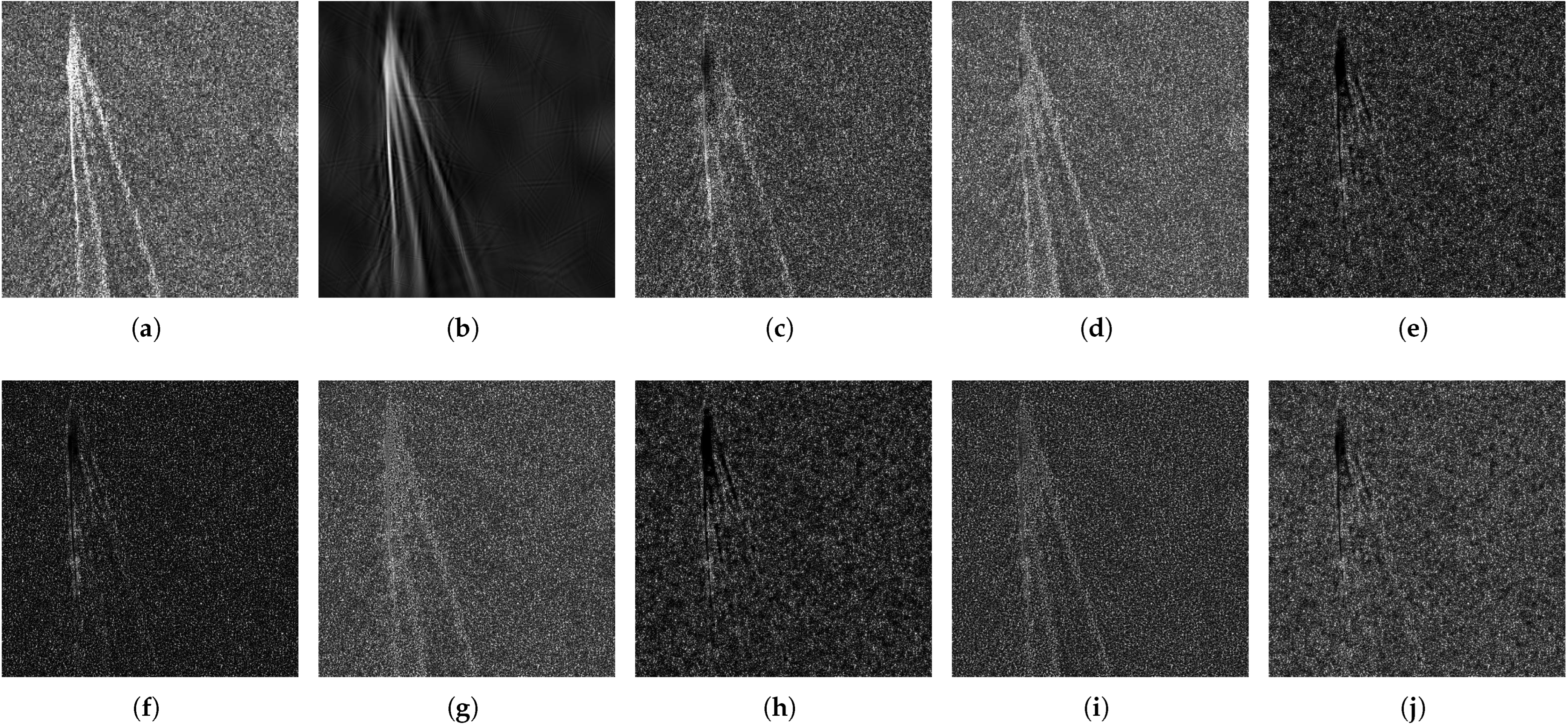
3.1. Experiments on Incoherence Constraint

Experiments based on simulated and real images are employed to study in detail the proposed image incoherence constraint method, and different incoherence parameters are considered to investigate the effect of the incoherence constraint.
Different triangles and the same square target are placed in two simulated scenes, and random noise with a signal-to-noise ratio of 6 dB is added to the simulated images. The two simulated images are shown in Figure 1a,b, and it can be seen that the two images have the same square target component. To eliminate the similarity between Figure 1a,b, the incoherence constraint is performed on Figure 1a based on Figure 1b. The theory of incoherence constraint is described in Section 2.2.1, and the algorithm is shown in Algorithm 1. Ideally, the square target in Figure 1a is completely eliminated, while the images of other parts remain unchanged. The proposed algorithm segments the image into uniformly sized blocks of size B × B and performs incoherent processing on them based on the pixels within the blocks. The size of the block will affect the results of the incoherent processing. The processed results of selecting block size B = 30 and B = 6 are shown in Figure 1c and Figure 1d, respectively. It can be seen that larger image blocks will cause the blocking artifact on the edges of a square object in Figure 1c, while smaller image blocks of Figure 1d will damage the triangular target due to the poor differentiation ability. In this simulation scenario, the value of B is selected as 10. When performing incoherent processing on image blocks, the value of the incoherence parameter determines the degree of target elimination. Since the incoherence parameter is determined by the logistic function (13), different parameter values of the logistic function have a significant impact on the incoherent results. When other parameter values remain as B = 10 , δ = 2 , and β = 30 , Figure 1e–g show the incoherent processing results with parameter values γ = 0.85 , γ = 0.95 , and γ = 0.99 , respectively. Since the coherent square targets in Figure 1a,b have the highest similarity, and the similarity between the triangle and the noise is lower, according to the characteristics of the logistic function, the γ parameter is the similarity value when the incoherence parameter at the midpoint, which serves as the threshold for distinguishing coherent and incoherent components. As analyzed, the processed result of Figure 1e shows that when the γ parameter is small, γ = 0.85 , the square target is effectively eliminated, while the intensity of the triangle target in Figure 1a will also be suppressed, and the artifact of the triangle in the lower right corner of Figure 1b is introduced. As the value of γ increases, the loss of the triangle target gradually decreases. When γ is 0.95, the incoherent result shown in Figure 1f can effectively eliminate the square target while keeping the triangle target unchanged. However, when the value γ = 0.99 is larger, the result of Figure 1g shows that the incoherence constraint has a weakened effect on eliminating the square target. Obviously, for this simulation scenario, γ = 0.95 can achieve the best incoherence effect.
In addition to the γ parameter, the logistic function has other parameters δ and β . When keeping γ = 0.95 unchanged, the incoherent results of δ = 1 and δ = 4 are shown in Figure 1h,i. Compared with Figure 1f ( δ = 2 ), it can be seen that when the parameter δ is too small δ = 1 , the rectangular target cannot be eliminated well, as shown in Figure 1h, and when δ is too large δ = 4 , the retention of the incoherent target will be adversely affected as shown in Figure 1i. Similarly, the experimental result with the parameter β = 6 is shown in Figure 1j. Because the similarity between coherent targets and incoherent targets is clearly distinguished, the steep S-shaped parameter curve has a positive effect on incoherent processing. Therefore, the result of the smaller parameter β = 6 in Figure 1j reduces the incoherent components that should be retained, while the incoherent processing result of Figure 1f ( β = 30 ) has met expectations, that is, the coherent square target is effectively eliminated and other components are retained.
TerraSAR-X (TSX) is a German X-band SAR satellite launched in 2007, and a cropped TSX image with a resolution of 3 m acquired from Italy is used as the real experimental image. The original TSX image is shown in Figure 2a, and the target image separated by the conventional MCA method is shown in Figure 2b. These two images are used as input images of the incoherence constraint. Since there are common ship wake components in the two input images, which means that the two images are coherent, the clutter component should be retained only after ideal incoherence constraint processing. The processed results with different parameters are given in Figure 2c–j. First, the effect of block sizes is studied. Since the ship wakes are narrow, straight lines, there are many clutter pixels in the large-size image block, and the ship wake pixels are obscured. Therefore, the ship wakes at the bottom of Figure 2c with a large-size image block B = 20 cannot be well eliminated. In this experiment, a smaller block size B = 6 is chosen. Next, three logistic function parameters that describe the incoherence parameter are studied. With fixed parameters B = 6 , δ = 2 , β = 40 , the processed results of different parameters γ are shown in Figure 2d–f. It can be seen that the target component decreases with decreasing γ parameter. Clear target components exist in Figure 2d with lager parameter γ = 0.97 , and almost only clutter components are preserved in Figure 2e by using an appropriate parameter γ = 0.91 ; when the γ takes a smaller value 0.85 , the target and clutter components in Figure 2f are eliminated together. Taking Figure 2e as the reference image ( δ = 2 ), setting the value of parameter δ to 1 and 4, and keeping other parameters unchanged, the processed results of different δ parameters are shown in Figure 2g,h. Parameter δ controls the amplitude of the incoherence parameters of all image blocks. When δ is too small, δ = 1 , the target cannot be effectively removed as shown in Figure 2g. When the δ is too large, δ = 4 , the clutter components will be eliminated to a certain extent as shown in Figure 2h. Similarly, taking Figure 2e as the reference image ( β = 40 ), a smaller parameter β = 6 makes the incoherence parameter unable to reach the maximum value at a larger similarity, so the result of Figure 2i still contains the target component. When a larger parameter β = 60 is selected, it can be seen that the ship wake targets with larger similarity are well eliminated in Figure 2j. Obviously, different logistic parameters control different aspects of the incoherence parameter, so by observing the processed results and combining prior knowledge of the parameters mentioned above, the various parameters can be empirically adjusted to reach satisfying results.
The experimental results in Figure 1f and Figure 2e prove that when appropriate incoherence parameters are selected, the proposed incoherence constraint method can effectively reduce the same components in the coherent images, verifying the effectiveness of the proposed incoherence constraint method.

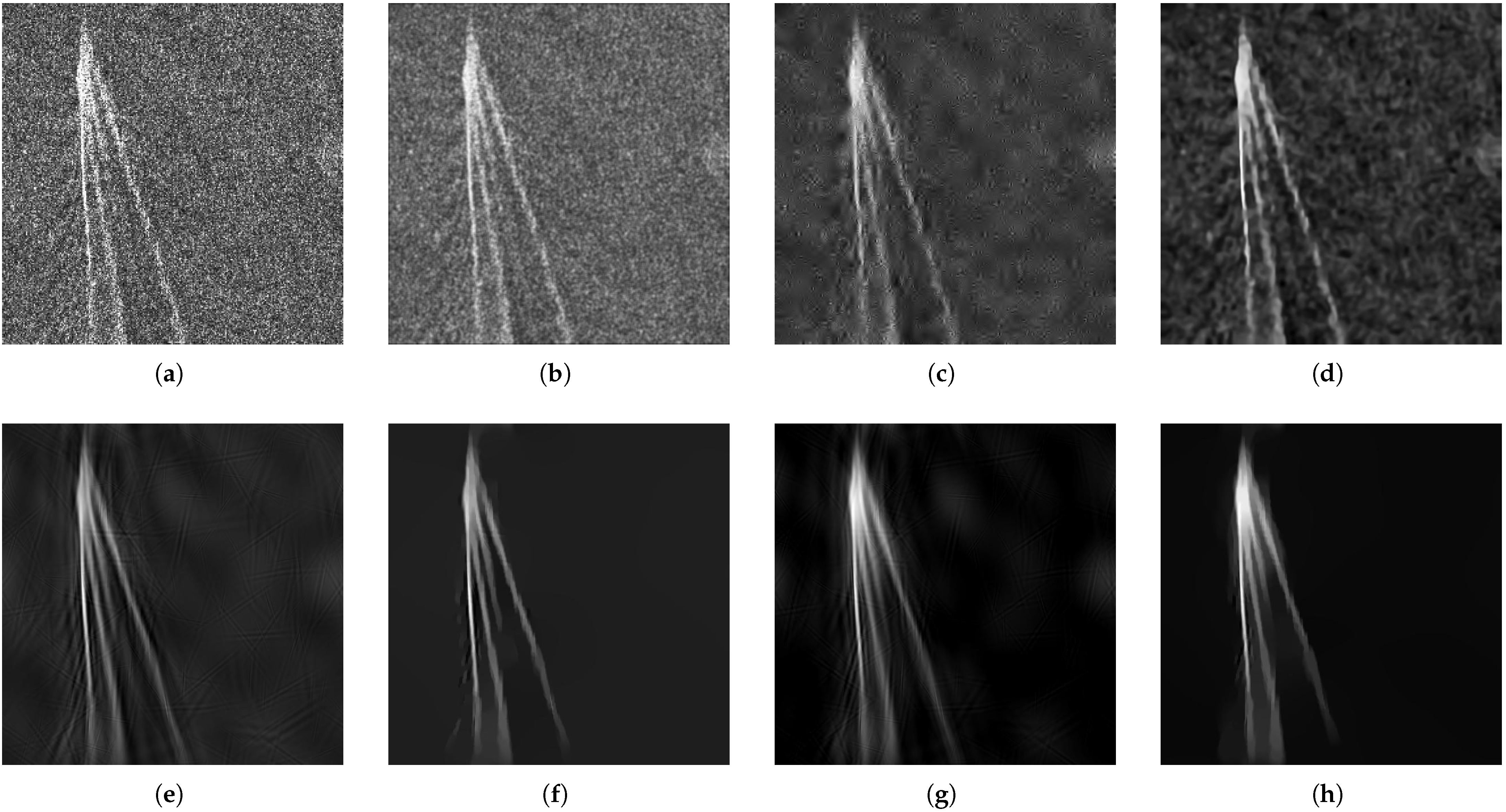
3.2. Experiments of Modified MCA Method

In this section, experimental results on real TSX and FARAD SAR images are provided to verify the effectiveness of the proposed method in comparison with the Lee filter [6], the wavelet filter [9], BM3D [10], and the conventional MCA method [16]. The background suppression factor (BSF) and the target-to-clutter ratio (TCR) are employed to quantitatively assess the clutter suppression performance [35,36,37].
The BSF is an objective evaluation index of the image background suppression effect, which can reflect the background change in the image:
BSF = σ c b σ c a ,
where σ c b and σ c a are the standard deviations of the clutter area before and after the processing. The larger the BSF is, the flatter the background clutter area, and the better the smoothing effect.
The TCR can effectively reflect the contrast between the target and the clutter in the image, which is calculated by the following:
TCR = 10 log 1 N t n T r | X ( n ) | 2 1 N c n C r | X ( n ) | 2 ,
where T r and C r represent the target area and the clutter area, respectively, and N t and N c are the numbers of pixels in the target and clutter areas, respectively. The larger the TCR is, the stronger the contrast between target and clutter, and the better the clutter suppression.

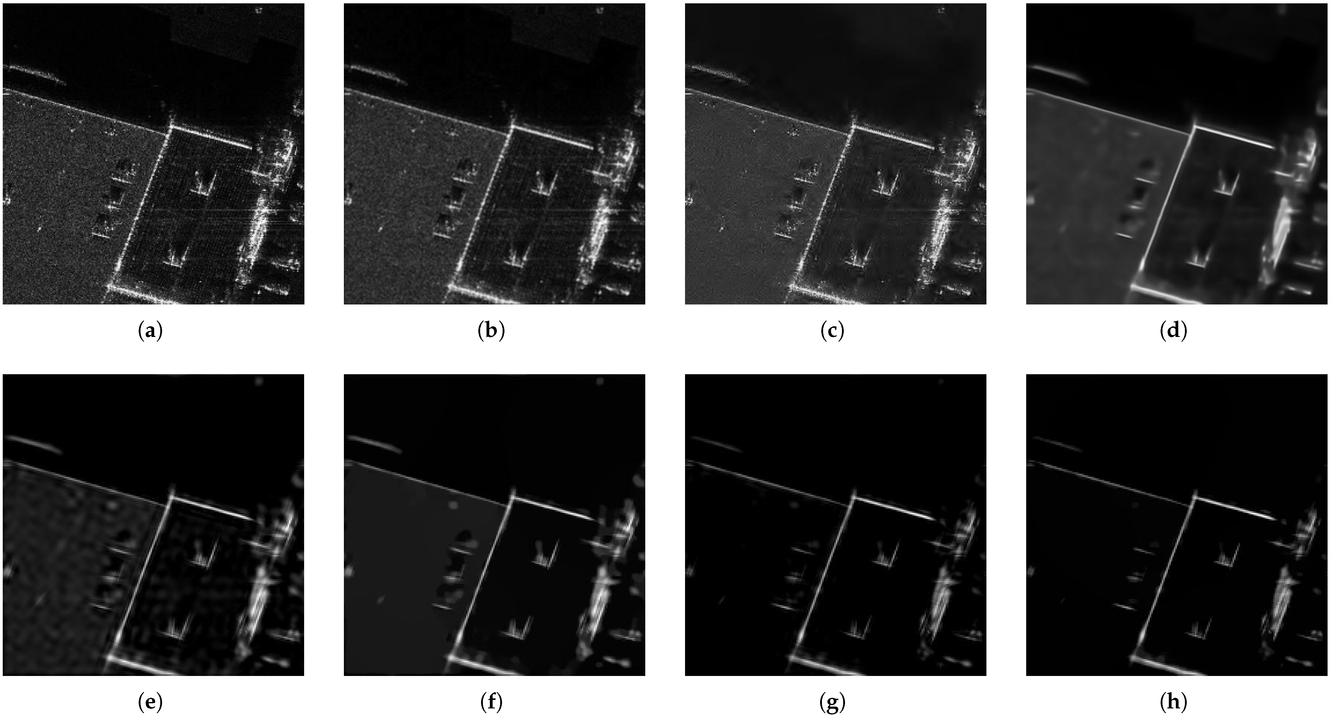
3.2.1. Results with TSX Images

The cropped TSX images with a resolution of 3 m, which are acquired from Italy and Turkey, are used as experimental images. The results of two TSX images processed by different methods are shown in Figure 3 and Figure 4, corresponding to sea surface and coastal scenes, respectively. For the two scenes, the Lee filter is implemented with a 3 × 3 window; the wavelet filter is performed with soft thresholding of a Daubechies length-four filter; the conventional MCA method is performed with M = 4 iterations, and the curvelet dictionary is selected to sparsely represent the target component. Taking the remaining part of the original SAR image minus the target component in the first MCA iteration as the initial training sample, the ODL is applied to update the clutter dictionary, and the number of dictionary learning iterations is set to Q = 2 in the conventional MCA method.
To further demonstrate the effectiveness of the proposed modified MCA method in detail, ablation experiments of the MCA method with L 0 gradient minimization and the MCA method with incoherence constraint are used to verify the performance of the L 0 gradient minimization and the incoherence constraint. In the ablation experiment, the parameters involved in the MCA method with L 0 gradient minimization and the MCA method with incoherence constraint are consistent with the modified MCA method. In the sea surface scene, the incoherence parameter of the modified MCA method is determined by the logistic function. The logistic parameters are set as B = 6 , δ = 2 , β = 40 , and γ = 0.92 ; the regularization parameters are empirically set as λ = 1 and ξ = 0.003 , and the other parameters are consistent with those in the conventional MCA method. For the coastal scene, the regularization parameters are empirically determined to be λ = 1 , ζ = 0.002 for the modified MCA method, and the logistic parameters are set as B = 8 , δ = 1.5 , β = 40 , γ = 0.89 .
The original image of the sea surface scene is shown in Figure 3a, where sea clutter has a negative impact on the ship wake detection result. The result of Lee filtering is shown in Figure 3b, where the contrast between the ship wake and the clutter is barely increased, and the target edge is blurred. The edge suffers a substantial loss of structural information, and the disturbing artifacts can be seen in Figure 3c, which displays the wavelet filtering result. In Figure 3d, BM3D filter also fails to remove the stronger clutter. In Figure 3e, the conventional MCA method achieves a good clutter suppression effect through image decomposition, but artifacts are also introduced due to the sparse reconstruction of the dictionaries. The L 0 gradient minimization can smooth the target image in a global manner, and clutter and artifacts can be better eliminated, as shown in Figure 3f. Since the MCA method with incoherence constraint achieves low mutual coherence between different components, better target separation and a clearer ship wake can be seen in Figure 3g, but there is still a small amount of pseudo-curve interference. The modified MCA method performs best in clutter suppression as shown in Figure 3h, where the artifacts are eliminated and the contrast between the target and the clutter is visually improved.
As shown in Figure 4a, the original image of the coastal scene is surrounded by a large amount of sea clutter and noise. The result obtained by the Lee filter is shown in Figure 4b, where the sea clutter and noise are reduced, but the image deteriorates and blurs to a certain extent. In Figure 4c, the wavelet filter provides poor edge preservation, and some unwanted artifacts are generated during the filtering process. In Figure 4d, the filtering result of BM3D contains artifacts of clutter, and the target component cannot be separated from the clutter as clearly. By using the conventional MCA to decompose the SAR image, the result in Figure 4e shows that compared with Figure 4a–d, the clutter suppression effect is improved greatly, but the image suffers from artifacts around the edges. Since the MCA with L 0 gradient minimization method has the capability to remove artifacts, the image quality of Figure 4f is improved compared with that of Figure 4e. The proposed MCA with incoherence constraint achieves success in target separation and clutter suppression, because the use of the incoherence constraint ensures that the separated target and clutter components are uncorrelated, but artifacts still exist in Figure 4g. In Figure 4h, the artifacts of the homogeneous areas are eliminated, edges and other linear features are preserved and enhanced. Since the separated clutter image with a higher proportion of sea clutter is used as training data for clutter dictionary learning, a learned clutter dictionary that mainly captures the features of sea clutter is constructed, making the modified MCA method more effective in suppressing sea clutter than ground clutter. However, it cannot be ignored that the modified MCA method can suppress both sea clutter and ground clutter simultaneously, and the suppression effect on each type of clutter is better than the comparison methods.
The BSF and TCR of the TSX images processed by different methods are listed in Table 1. It can be seen from the quantitative evaluation results that all methods have achieved larger BSF or TCR values than the original images, which means that all methods can suppress the clutter to some extent. The conventional MCA method performs better by separating target components from SAR images in comparison to the Lee filter, wavelet filter, and BM3D methods. Since both TSX images are sparse scenes containing a large amount of sea surface, after L 0 smoothing, most gradients in the clutter region become zero; that is, the standard deviation of the clutter region is relatively small, which significantly improves the BSF evaluation metrics of the MCA method with L 0 gradient minimization. The MCA method with incoherence constraint minimizes the correlation of each component, improves the separation result, and has a higher TCR evaluation value than the conventional MCA method, which is consistent with the processed results shown in Figure 3 and Figure 4. Among all the methods, the proposed modified MCA method provides the best evaluation results, which can effectively suppress clutter while enhancing image contrast by jointly employing incoherence constraints and L 0 gradient minimization processing.

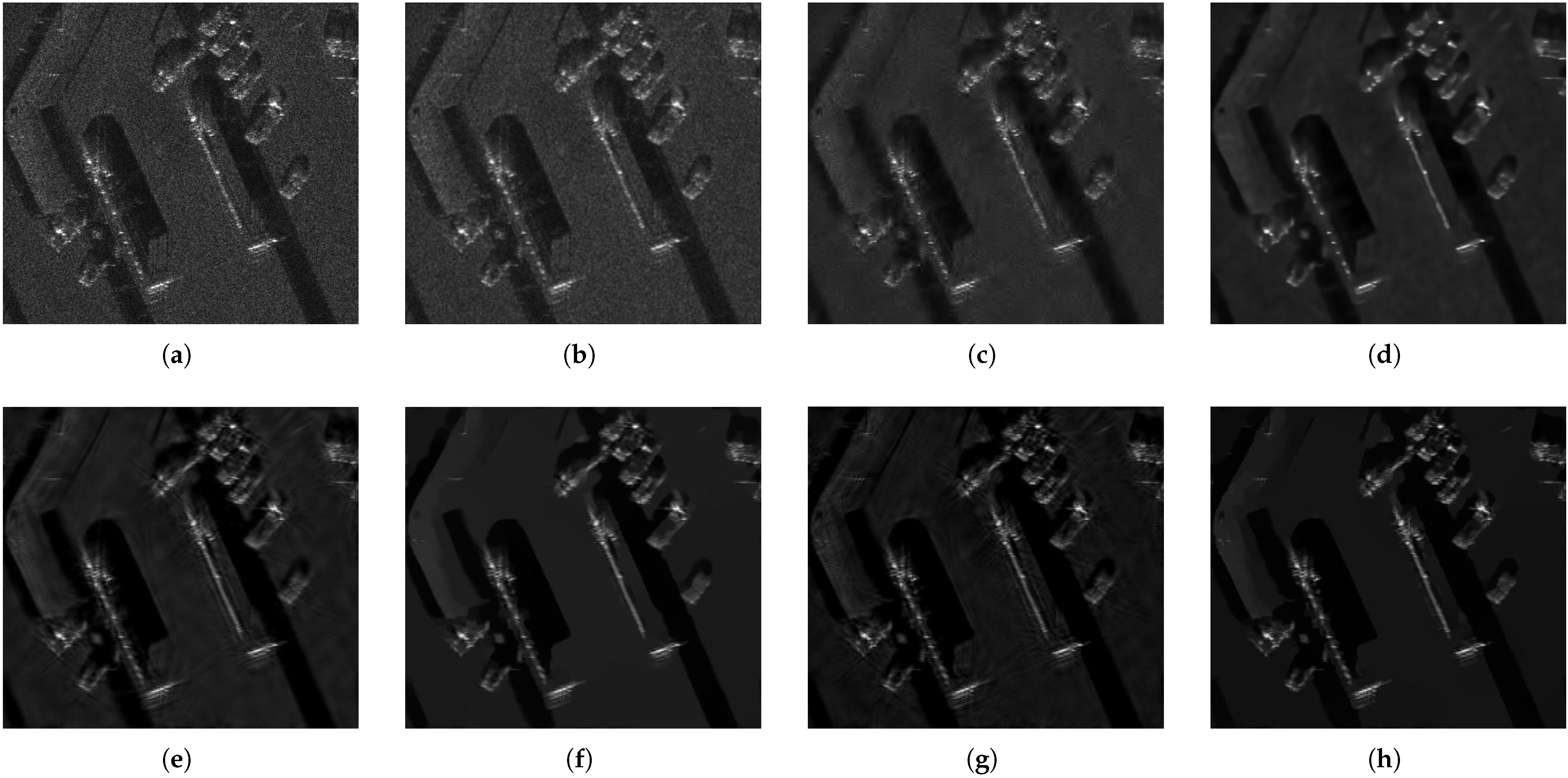
3.2.2. Results with FARAD Images

The cropped FARAD Ka-band and X-band images with a 4-inch resolution from the Sandia National Laboratories, USA, are used as another experimental SAR image to validate the proposed method. The original image and a series of processed results are shown in Figure 5 and Figure 6. The Lee filter with a 3 × 3 window size and the Daubechies wavelet of a length-four filter with classical soft thresholding are adopted for clutter suppression in the experiment. Meanwhile, the conventional MCA method with the number of iterations M = 4 is also employed, which uses the curvelet transform and ODL to construct the dictionaries of target and clutter, respectively, and the number of dictionary learning iterations Q = 2 . For the proposed method, the shared parameters and corresponding dictionaries with the conventional MCA are set to be the same for a fair comparison. For the modified MCA method, the regularization parameters of the two images are set as λ = 1 and ξ = 0.002 ; the logistic parameters are empirically chosen as B = 10 , δ = 1.6 , β = 40 , γ = 0.93 in the Ka-band image, and B = 8 , δ = 1 , β = 40 , γ = 0.91 in the X-band image. The ablation experiments of the MCA method with L 0 gradient minimization and the MCA method with incoherence constraint share the same parameter values as the modified MCA method.
From Figure 5a, it is noticed that the FARAD Ka-band image of the buildings is surrounded by ground clutter. As shown in Figure 5b, although the Lee filter has smoothed most of the ground clutter, it causes blurring of linear features and fine details of the buildings. As seen from Figure 5c, some artifacts in homogeneous regions and the limited ability of edge reconstruction are unavoidable, although the wavelet filter can obtain acceptable results. In Figure 5d, the clutter is reduced by the BM3D method, but some disturbing artifacts still exist. Similarly, in Figure 5e, the conventional MCA method also introduces artifacts while suppressing clutter. In Figure 5f, the MCA method with L 0 gradient minimization smoothes the homogeneous areas and preserves clear edges without artifacts, demonstrating the artifact suppression capability of the L 0 gradient minimization. As for the MCA with incoherence constraint, better clutter suppression performance is achieved compared to the conventional MCA method. Figure 5g visualizes better target component separation results with sharper edges, and at the same time, very few artifacts are introduced. In Figure 5h, a close inspection reveals that the modified MCA method can both reduce artifacts and better preserve the target, which shows the effectiveness of jointly utilizing the incoherence constraint and the L 0 gradient minimization in clutter suppression.
The original FARAD X-band image interfered by ground clutter is given in Figure 6a. In Figure 6b, the Lee filter produces a blurry image and has limitations in retaining the local features and subtle details of the cars. Comparing the filtered images in Figure 6c,d with the original image, the image quality is improved by wavelet filtering and BM3D filtering, but the edge preservation effect of cars and linear targets needs to be improved. Figure 6e is the reconstruction result of the conventional MCA method, which reduces the clutter and noise by image decomposition, but it generates artifacts that do not exist in the original SAR image. Figure 6f shows that the L 0 gradient minimization has the advantage of artifact removal thanks to its special global smoothing ability. In Figure 6g, the MCA method with incoherence constraint can also suppress clutter without destroying important structural edges, but it also needs further smoothing to remove artifacts. From the comparison between Figure 6h and the others, the modified MCA eliminates unwanted artifacts and obtains the best clutter suppression result, showing a good target enhancement ability.
To further compare the clutter suppression effect of different methods, the BSF and TCR evaluation results of the FARAD images are listed in Table 2. It can be seen that the evaluation values of the Lee filter, wavelet filter, and BM3D methods are lower than those of the proposed methods, indicating that the three methods have limited success in clutter suppression. The artifacts will be introduced when using the conventional MCA method to decompose SAR images, and image quality can be further improved by restoring artifact-free targets. Regarding the MCA result with L 0 gradient minimization, the homogeneous area with artifacts will be as smooth as possible, so the BSF evaluation result based on the standard deviation of the clutter area can achieve a larger value. As expected, adding an incoherence constraint to the MCA model can eliminate the clutter components in the target image, reduce the grayscale value of the clutter area, and lead to a significant improvement in the TCR evaluation results. Consequently, the modified MCA method integrating the incoherence constraint and L 0 gradient minimization achieves the highest performance index values in all the experimental images, demonstrating its superior performance in clutter suppression and target feature preservation.

4. Discussion

In addition to the clutter suppression effect, the computation time is an important performance metric. A comparison of the computation time of the seven methods in the experiment is shown in Table 3. A desktop computer with an Intel CPU E5-2680 processor and 192GB of main memory is used in the experiments. The computation time is determined by recording the average value of several measurements. As shown in Table 3, the MCA-based methods are noticeably slower than traditional filter methods here, which contrasts with their excellent performance in clutter suppression. This difference can mainly be attributed to two factors: the MCA-based method involves an iterative process, and the computational complexity of sparse representation is relatively high. Furthermore, compared with the conventional MCA method, the proposed modified MCA method mainly involves two improvements: the introduction of the incoherence constraint and the replacement of TV regularization with L 0 gradient minimization. Since the incoherence constraint reduces its own computational complexity by dividing the image into blocks, and the complexity of L 0 gradient minimization and TV regularization is comparable, the computation time of the MCA method with L 0 gradient minimization and the MCA method with incoherence constraint is only slightly increased compared to the conventional MCA method. The modified MCA method combines an incoherence constraint with L 0 gradient minimization, which leads to the longest computation time, but the main computational complexity still originates from the conventional MCA method.
In the future, research work can be conducted in the following two aspects:
First, a favorable target dictionary is the key factor in deciding whether target features can be effectively preserved during the clutter suppression process, so the selection of the target dictionary cannot be ignored. As shown in Figure 5, in this experiment, only the curvelet dictionary is used to extract the linear features of the target, which inevitably causes the loss of some weak point targets. Since one fixed dictionary may only be able to sparsely represent a certain type of target features, it is an inevitable trend to consider using a combination of multiple target dictionaries to enhance the ability to retain target features.
Second, the proposed modified MCA method achieves more effective clutter suppression at the expense of increased computation time. Future research can focus on simplifying the solution process of the optimization problem and reducing the computational complexity of the conventional MCA algorithm to make it more suitable for real-time applications or resource-constrained environments.

5. Conclusions

A modified MCA method has been proposed for SAR image clutter suppression. First, an incoherence constraint method is proposed, which can effectively remove the coherent components of images. Then, L 0 gradient minimization is exploited to smooth the homogeneous regions and simultaneously preserve the edges in the target image. By incorporating the incoherence constraint and L 0 gradient minimization with the conventional MCA, the modified MCA problem is formulated. The corresponding optimization problem is solved by alternately updating the variables. Experimental results with both TSX and FARAD images have been provided to verify the superior performance of the proposed modified MCA method in suppressing clutter in SAR images.

Author Contributions

Conceptualization, S.X. and H.X.; methodology, S.X. and B.S.; validation, S.X.; writing—original draft preparation, S.X.; writing—review and editing, H.X., B.S. and W.L.; supervision, H.X. and B.S. All authors have read and agreed to the published version of the manuscript.

Funding

This work was supported in part by the National Key Research and Development Program of China under Grant 2022YFB3902302, and in part by the National Natural Science Foundation of China under Grant U2241202.

Data Availability Statement

TerraSAR-X data are available at https://download.geoservice.dlr.de/supersites/files/ (accessed on 10 February 2024). FARAD SAR data are available at https://www.sandia.gov/radar/pathfinder-radar-isr-and-synthetic-aperture-radar-sar-systems/complex-data/ (accessed on 20 March 2024).

Acknowledgments

The authors would like to thank the European Space Agency (ESA) and Sandia National Laboratories for providing free TerraSAR-X and FARAD SAR data. The authors would also like to thank the anonymous reviewers for their valuable comments and useful suggestions.

Conflicts of Interest

The authors declare no conflicts of interest.

Abbreviations

The following abbreviations are used in this manuscript:
SARsynthetic aperture radar
MCAmorphological component analysis
DPCA displaced phase center antenna
STAPspace-time adaptive processing
BM3Dblock-matching and 3D-filtering
SVDsingular value decomposition
PCAprincipal component analysis
CNNconvolutional neural network
GANgenerative adversarial network
GPRground-penetrating radar
UDWTun-decimated discrete wavelet transform
ATRautomatic target recognition
BCDblock coordinate descent
TVtotal variation
DCTdiscrete cosine transform
MODmethod of optimal direction
K-SVDK-singular value decomposition
ODLonline dictionary learning
TSXTerraSAR-X
BSFbackground suppression factor
SCRSignal-to-clutter ratio

References

  1. Song, Q.; Xu, F. Zero-Shot Learning of SAR Target Feature Space with Deep Generative Neural Networks. IEEE Geosci. Remote Sens. Lett. 2017, 14, 2245–2249. [Google Scholar] [CrossRef]
  2. Wang, B.; Song, C.; Liu, N.; Liu, Z.; Zhou, L.; Xiang, M. An Advanced Lightweight Dual-Band Digital Array SAR System: Earth Observation Imaging and Moving Target Detection. IEEE Sens. J. 2023, 23, 21776–21786. [Google Scholar] [CrossRef]
  3. Suwa, K.; Yamamoto, K.; Tsuchida, M.; Nakamura, S.; Wakayama, T.; Hara, T. Image-Based Target Detection and Radial Velocity Estimation Methods for Multichannel SAR-GMTI. IEEE Trans. Geosci. Remote Sens. 2017, 55, 1325–1338. [Google Scholar] [CrossRef]
  4. Yang, T.; Wang, Y.; Li, W. A Moving Target Imaging Algorithm for HRWS SAR/GMTI Systems. IEEE Trans. Aerosp. Electron. Syst. 2017, 53, 1147–1157. [Google Scholar] [CrossRef]
  5. Zhao, X.; Jiang, Y.; Wang, W.Q. Efficient Clutter Suppression in SAR Images with Shedding Irrelevant Patterns. IEEE Geosci. Remote Sens. Lett. 2015, 12, 1828–1832. [Google Scholar] [CrossRef]
  6. Lee, J.S. Digital Image Enhancement and Noise Filtering by Use of Local Statistics. IEEE Trans. Pattern Anal. Mach. Intell. 1980, PAMI-2, 165–168. [Google Scholar] [CrossRef]
  7. Frost, V.S.; Stiles, J.A.; Shanmugan, K.S.; Holtzman, J.C. A Model for Radar Images and Its Application to Adaptive Digital Filtering of Multiplicative Noise. IEEE Trans. Pattern Anal. Mach. Intell. 1982, PAMI-4, 157–166. [Google Scholar] [CrossRef]
  8. Acito, N.; Corsini, G.; Diani, M.; Pennucci, G. Comparative analysis of clutter removal techniques over experimental IR images. Opt. Eng. 2005, 44, 106401. [Google Scholar] [CrossRef]
  9. Sendur, L.; Selesnick, I. Bivariate shrinkage functions for wavelet-based denoising exploiting interscale dependency. IEEE Trans. Signal Process. 2002, 50, 2744–2756. [Google Scholar] [CrossRef]
  10. Dabov, K.; Foi, A.; Katkovnik, V.; Egiazarian, K. Image Denoising by Sparse 3-D Transform-Domain Collaborative Filtering. IEEE Trans. Image Process. 2007, 16, 2080–2095. [Google Scholar] [CrossRef]
  11. Abujarad, F.; Nadim, G.; Omar, A. Clutter reduction and detection of landmine objects in ground penetrating radar data using singular value decomposition (SVD). In Proceedings of the 3rd International Workshop on Advanced Ground Penetrating Radar, Delft, The Netherlands, 2–3 May 2005; IWAGPR 2005. pp. 37–42. [Google Scholar] [CrossRef]
  12. Lu, Q.Q.; Pu, J.X.; Wang, X.H.; Liu, Z.H. A clutter suppression algorithm for GPR data based on PCA combining with gradient magnitude. Appl. Mech. Mater. 2014, 644, 1662–1667. [Google Scholar] [CrossRef]
  13. Zhao, Y.; Yang, X.; Qu, X.; Lan, T.; Gong, J. Clutter Removal Method for GPR Based on Low-Rank and Sparse Decomposition With Total Variation Regularization. IEEE Geosci. Remote Sens. Lett. 2023, 20, 1–5. [Google Scholar] [CrossRef]
  14. Yan, H.; Chen, C.; Jin, G.; Zhang, J.; Wang, X.; Zhu, D. Implementation of a Modified Faster R-CNN for Target Detection Technology of Coastal Defense Radar. Remote Sens. 2021, 13, 1703. [Google Scholar] [CrossRef]
  15. Guo, J.; Lei, B.; Ding, C.; Zhang, Y. Synthetic Aperture Radar Image Synthesis by Using Generative Adversarial Nets. IEEE Geosci. Remote Sens. Lett. 2017, 14, 1111–1115. [Google Scholar] [CrossRef]
  16. Starck, J.L.; Elad, M.; Donoho, D. Image decomposition via the combination of sparse representations and a variational approach. IEEE Trans. Image Process. 2005, 14, 1570–1582. [Google Scholar] [CrossRef]
  17. Temlioglu, E.; Erer, I. Clutter Removal in Ground-Penetrating Radar Images Using Morphological Component Analysis. IEEE Geosci. Remote Sens. Lett. 2016, 13, 1802–1806. [Google Scholar] [CrossRef]
  18. Wagner, S. Morphological Component Analysis in SAR images to improve the generalization of ATR systems. In Proceedings of the 2015 3rd International Workshop on Compressed Sensing Theory and Its Applications to Radar, Sonar and Remote Sensing (CoSeRa), Pisa, Italy, 17–19 June 2015; pp. 46–50. [Google Scholar] [CrossRef]
  19. Yang, G.; Yu, J.; Xiao, C.; Sun, W. Ship wake detection for SAR images with complex backgrounds based on morphological dictionary learning. In Proceedings of the 2016 IEEE International Conference on Acoustics, Speech and Signal Processing (ICASSP), Shanghai, China, 20–25 March 2016; pp. 1896–1900. [Google Scholar] [CrossRef]
  20. Fadili, M.J.; Starck, J.L.; Bobin, J.; Moudden, Y. Image Decomposition and Separation Using Sparse Representations: An Overview. Proc. IEEE 2010, 98, 983–994. [Google Scholar] [CrossRef]
  21. Xu, L.; Lu, C.; Xu, Y.; Jia, J. Image smoothing via L0 gradient minimization. In Proceedings of the 2011 SIGGRAPH Asia Conference, Association for Computing Machinery, Hong Kong, China, 12–15 December 2011; Volume 30, pp. 1–12. [Google Scholar] [CrossRef]
  22. Starck, J.L.; Moudden, Y.; Bobin, J.; Elad, M.; Donoho, D.L. Morphological component analysis. In Wavelets XI. International Society for Optics and Photonics; SPIE: Bellingham, WA, USA, 2005; Volume 5914, p. 59140Q. [Google Scholar] [CrossRef]
  23. Kong, S.; Wang, D. A dictionary learning approach for classification: Separating the particularity and the commonality. In European Conference on Computer Vision; Springer: Berlin/Heidelberg, Germany, 2012; pp. 186–199. [Google Scholar] [CrossRef]
  24. Donoho, D.L.; Huo, X. Uncertainty principles and ideal atomic decomposition. IEEE Trans. Inf. Theory 2001, 47, 2845–2862. [Google Scholar] [CrossRef]
  25. Zhang, J. Gradient descent based optimization algorithms for deep learning models training. arXiv 2019, arXiv:1903.03614. [Google Scholar]
  26. Yuan, Q.; Zhang, L.; Shen, H. Multiframe Super-Resolution Employing a Spatially Weighted Total Variation Model. IEEE Trans. Circuits Syst. Video Technol. 2012, 22, 379–392. [Google Scholar] [CrossRef]
  27. Beck, A.; Teboulle, M. A fast iterative shrinkage-thresholding algorithm for linear inverse problems. SIAM J. Imaging Sci. 2009, 2, 183–202. [Google Scholar] [CrossRef]
  28. Bobin, J.; Starck, J.L.; Fadili, J.M.; Moudden, Y.; Donoho, D.L. Morphological Component Analysis: An Adaptive Thresholding Strategy. IEEE Trans. Image Process. 2007, 16, 2675–2681. [Google Scholar] [CrossRef]
  29. Daubechies, I. The wavelet transform, time-frequency localization and signal analysis. IEEE Trans. Inf. Theory 1990, 36, 961–1005. [Google Scholar] [CrossRef]
  30. Starck, J.L.; Candes, E.; Donoho, D. The curvelet transform for image denoising. IEEE Trans. Image Process. 2002, 11, 670–684. [Google Scholar] [CrossRef] [PubMed]
  31. Qayyum, A.; Malik, A.S.; Naufal, M.; Saad, M.; Mazher, M.; Abdullah, F.; Abdullah, T.A.R.B.T. Designing of overcomplete dictionaries based on DCT and DWT. In Proceedings of the 2015 IEEE Student Symposium in Biomedical Engineering and Sciences (ISSBES), Shah Alam, Malaysia, 4 November 2015; pp. 134–139. [Google Scholar] [CrossRef]
  32. Engan, K.; Aase, S.; Hakon Husoy, J. Method of optimal directions for frame design. In Proceedings of the 1999 IEEE International Conference on Acoustics, Speech, and Signal Processing, Proceedings, ICASSP99 (Cat. No.99CH36258), Phoenix, AZ, USA, 15–19 March 1999; Volume 5, pp. 2443–2446. [Google Scholar] [CrossRef]
  33. Aharon, M.; Elad, M.; Bruckstein, A. K-SVD: An algorithm for designing overcomplete dictionaries for sparse representation. IEEE Trans. Signal Process. 2006, 54, 4311–4322. [Google Scholar] [CrossRef]
  34. Mairal, J.; Bach, F.; Ponce, J.; Sapiro, G. Online dictionary learning for sparse coding. In Proceedings of the 26th Annual International Conference on Machine Learning, Association for Computing Machinery, Montreal, QC, Canada, 14–18 June 2009; pp. 689–696. [Google Scholar] [CrossRef]
  35. Deng, X.; Wang, Y.; He, D.; Han, G.; Xue, T.; Hao, Y.; Zhuang, X.; Liu, J.; Zhang, C.; Wang, S. A Compact Mid-Wave Infrared Imager System with Real-Time Target Detection and Tracking. IEEE J. Sel. Top. Appl. Earth Obs. Remote Sens. 2022, 15, 6069–6085. [Google Scholar] [CrossRef]
  36. Tang, H.; Lu, D.; Wang, L.; Gu, G. Infrared sea clutter suppression method based on gradient filtering. In AOPC 2022: Optical Sensing, Imaging, and Display Technology; Jiang, Y., Wang, X., Wang, Y., Liu, D., Xue, B., Eds.; International Society for Optics and Photonics; SPIE: Bellingham, WA, USA, 2023; Volume 12557, p. 125572B. [Google Scholar] [CrossRef]
  37. Chen, X.; Chen, W. Clutter reduction based on coefficient of variation in through-wall radar imaging. In Proceedings of the 2013 IEEE Radar Conference (RadarCon13), Ottawa, ON, Canada, 29 April–3 May 2013; pp. 1–4. [Google Scholar] [CrossRef]
Figure 1. Incoherence constraint processing results of simulated images with different parameters: (a) simulated image; (b) coherent image of (a); (c) B = 30 , γ = 0.95 , δ = 2 , β = 30 ; (d) B = 6 , γ = 0.95 , δ = 2 , β = 30 ; (e) B = 10 , γ = 0.85 , δ = 2 , β = 30 ; (f) B = 10 , γ = 0.95 , δ = 2 , β = 30 ; (g) B = 10 , γ = 0.99 , δ = 2 , β = 30 ; (h) B = 10 , γ = 0.95 , δ = 1 , β = 30 ; (i) B = 10 , γ = 0.95 , δ = 4 , β = 30 ; (j) B = 10 , γ = 0.95 , δ = 2 , β = 6 .
Remotesensing 17 01727 g001
Figure 2. Incoherence constraint processing results of TSX images with different parameters: (a) TSX image; (b) target image; (c) B = 20 , γ = 0.91 , δ = 2 , β = 40 ; (d) B = 6 , γ = 0.97 , δ = 2 , β = 40 ; (e) B = 6 , γ = 0.91 , δ = 2 , β = 40 ; (f) B = 6 , γ = 0.85 , δ = 2 , β = 40 ; (g) B = 6 , γ = 0.91 , δ = 1 , β = 40 ; (h) B = 6 , γ = 0.91 , δ = 4 , β = 40 ; (i) B = 6 , γ = 0.91 , δ = 2 , β = 6 ; (j) B = 6 , γ = 0.91 , δ = 2 , β = 60 .
Remotesensing 17 01727 g002
Figure 3. Clutter suppression results of the sea surface: (a) original SAR image; (b) Lee filter. (c) wavelet filter; (d) BM3D filter; (e) conventional MCA method; (f) MCA method with L 0 gradient minimization; (g) MCA method with incoherence constraint; (h) modified MCA method.
Remotesensing 17 01727 g003
Figure 4. Clutter suppression results of the coastal scene: (a) original SAR image; (b) Lee filter; (c) wavelet filter; (d) BM3D filter; (e) conventional MCA method; (f) MCA method with L 0 gradient minimization; (g) MCA method with incoherence constraint; (h) modified MCA method.
Remotesensing 17 01727 g004
Figure 5. Clutter suppression results of a FARAD Ka-band image: (a) original SAR image; (b) Lee filter; (c) wavelet filter; (d) BM3D filter; (e) conventional MCA method; (f) MCA method with L 0 gradient minimization; (g) MCA method with incoherence constraint; (h) modified MCA method.
Remotesensing 17 01727 g005
Figure 6. Clutter suppression results of a FARAD X-band image: (a) original SAR image; (b) Lee filter; (c) wavelet filter; (d) BM3D filter; (e) conventional MCA method; (f) MCA method with L 0 gradient minimization; (g) MCA method with incoherence constraint; (h) modified MCA method.
Remotesensing 17 01727 g006
Table 1. Evaluation Results for TSX Images.
MethodsSea Surface SceneCoastal Scene
BSF TCR (dB) BSF TCR (dB)
Original image1.004.791.008.12
Lee filter3.166.331.948.86
Wavelet filter1.853.434.419.50
BM3D filter4.2410.894.0615.87
Conventional MCA11.9512.444.4522.11
The MCA method with L 0 gradient minimization87.0113.5016.6323.58
The MCA method with incoherence constraint12.0324.644.9025.64
The modified MCA method89.0725.2817.0730.11
Table 2. Evaluation results for FARAD images.
MethodsFARAD Ka-Band ImageFARAD X-Band Image
BSF TCR (dB) BSF TCR (dB)
Original image1.008.551.005.24
Lee filter2.218.241.556.01
Wavelet filter1.584.612.146.15
BM3D filter7.808.432.276.67
Conventional MCA3.9411.872.026.76
The MCA method with L 0 gradient minimization56.4312.752.597.02
The MCA method with incoherence constraint8.8127.302.3310.20
The modified MCA method66.4033.982.7810.52
Table 3. Computation time of methods (s).
MethodsSea Scene of TSX ImageCoastal Scene of TSX ImageFARAD Ka-Band ImageFARAD X-Band Image
Lee filter12.087.996.028.40
Wavelet filter6.946.045.246.21
BM3D filter60.1938.1132.6546.31
Conventional MCA309.53200.61143.96221.45
The MCA method with L 0 gradient minimization321.10203.59149.26226.69
The MCA method with incoherence constraint323.27204.98151.11228.22
The modified MCA method332.43210.35156.57235.69
Disclaimer/Publisher’s Note: The statements, opinions and data contained in all publications are solely those of the individual author(s) and contributor(s) and not of MDPI and/or the editor(s). MDPI and/or the editor(s) disclaim responsibility for any injury to people or property resulting from any ideas, methods, instructions or products referred to in the content.

