Abstract
Air-coupled ground penetrating radar (GPR) systems are widely used for subsurface imaging in demining, geological surveys, and infrastructure assessment applications. However, strong surface reflections can introduce interference, leading to receiver saturation and reducing the clarity of subsurface features. This paper presents a novel surface reflection suppression algorithm for stepped-frequency continuous wave (SFCW) GPR systems. The proposed method estimates the surface reflection component and applies phase-compensated subtraction at the receiver site, effectively suppressing background reflections. A modular SFCW radar system was developed and tested in a laboratory setup simulating a low-altitude airborne deployment to validate the proposed approach. B-scan and time-domain analyses demonstrate significant suppression of surface reflections, improving the visibility of subsurface targets. Unlike previous static echo cancellation methods, the proposed method performs on-board pre-downconversion removal of surface clutter that compensates for varying ground distance, which is a unique contribution of this work.
1. Introduction
Ground penetrating radar (GPR) systems are essential tools for exploring below the surface, helping with tasks like geological surveys, infrastructure checks [1,2], archaeological investigations [3], environmental assessments [4], and other forms of subsurface exploration. The field of landmine detection using GPR has seen important advancements and is still an active research area. GPRs are able to detect subsurface characteristics without physical contact, which makes them useful in demining and other military applications. Innovations in signal processing, antenna design [5], and machine learning algorithms [6,7] have enhanced GPR accuracy and reliability for identifying landmines and differentiating them from clutter. Over the past few years, radars have increasingly been mounted on multi-rotor drones to enable fully contactless operation, allowing for faster surveys over hazardous or hard-to-reach areas while minimizing risk to human operators. This integration of GPR with aerial platforms has opened up new possibilities for large-scale and efficient subsurface mapping [8].
GPR systems mounted on drones are typically categorized into two types based on their signal transmission approach: pulsed radar [9,10,11] and continuous wave (CW) radar [12,13]. Both types have unique characteristics that make them suitable for specific applications, but when it comes to drone-mounted systems, CW radars are often favored for several reasons.
Pulsed radars operate by transmitting short-duration, high-energy pulses and measuring the time delay of returning echoes to determine target depth. While this approach enables precise time-of-flight calculations, the drawbacks are higher power consumption, complex receiver architectures, and a need for fast-switching, high-bandwidth electronics, which can be challenging to integrate into lightweight, airborne platforms.
CW radars transmit a continuous electromagnetic signal and analyze the amplitude and phase shift in the returning signal in infer depth and subsurface features. CW radars can operate at lower power levels, making them inherently more power-efficient and lightweight compared to their pulsed counterparts. This is beneficial for drone-mounted systems, where battery life and payload weight are key limitations [14]. Furthermore, the design of CW radars is often simpler and can be easier to optimize for specific frequencies needed for particular applications.
While there are also several drawbacks, one to point out is receiver saturation. The two main causes are usually either antenna direct coupling or, in applications such as air-coupled GPRs, signal reflection from the surface, which can be orders of magnitude stronger than reflection from subsurface features. While there are several passive and active approaches [15] when it comes to suppressing antenna crosstalk [16,17], the problem of surface reflection suppression is not well researched.
Deep-learning-based approaches have been investigated for GPR clutter removal, mostly as post-processing methods, demonstrating effective suppression of ground surface reflections but requiring extensive training data and limited generalizability to new conditions. Several studies propose end-to-end neural network architectures that can remove ground clutter as a post-processing step. In [18], the authors introduce a hybrid deep network for contextual feature fusion and spatial attention mechanisms to improve signal-to-clutter discrimination, which heavily relies on domain-specific training data and, while robust, is still sensitive to generalization issues across measurement environments. In [19], the authors address rebar-induced clutter using a VAE-GAN framework and demonstrate effective rebar clutter removal in tunnel inspections with supervised learning. While both methods demonstrate strong suppression capabilities, they are used as a post-processing step.
One approach to canceling out the static reflection, e.g., reflections from the targets that remain at the same distance throughout the entire measurement, was proposed in [20]. This method integrates an echo cancellation (EC) system into a SFCW radar to suppress static echoes. The system utilizes an additional RF synthesizer, synchronized with the transmitter, to generate a cancellation signal that mirrors the unwanted static reflection in amplitude but is 180° out of phase. By summing this cancellation signal with the received echoes, the method effectively removes static clutter while preserving the reflections from dynamic targets. This approach starts with the calibration, which ensures that the EC system correctly estimates the phase shift and amplitude for each frequency step. During this step, the radar measures the static scene. The system is particularly beneficial for applications such as air-coupled GPR and through-wall imaging radar (TWIR), where strong reflections from stationary surfaces can overshadow weaker signals from objects of interest. Experimental results show that the method can achieve up to 20 dB attenuation of static echoes, significantly enhancing the visibility of dynamic objects without increasing system size and power consumption. While this approach could be used for the suppression of surface reflections in airborne SFCW GPR systems, its effectiveness relies on maintaining a constant distance between the antenna and the ground throughout the entire measurement. Although theoretically feasible, practical challenges arise due to ground fluctuations. Therefore, we propose a method that actively accounts for these variations, ensuring robust performance even in scenarios where the ground elevation changes dynamically.
In this paper, we propose a novel phase-compensated subtraction technique for surface reflection suppression in air-coupled SFCW GPR systems. Unlike conventional filtering techniques that operate in the post-processing stage, our approach estimates the surface reflection component and subtracts it at the receiver site, significantly reducing its impact before down-conversion and sampling. The proposed method is validated through experimental laboratory measurements using a custom-designed modular SFCW radar system.
2. Working Principle of SFCW Radar and Theoretical Background
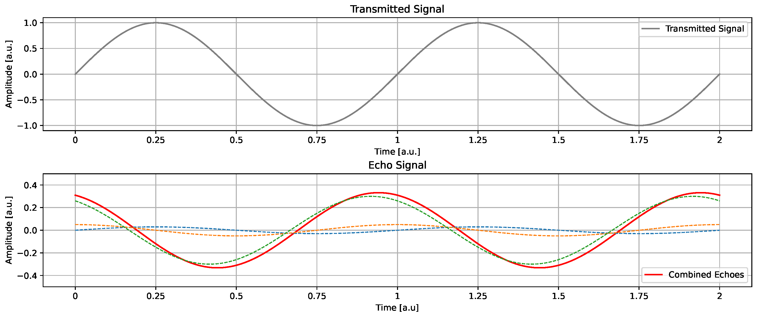
As the name implies, CW radars work by continuously transmitting waveforms, which may be considered pure sine waves. Radar signals reflect from stationary targets and return to the receiving unit, where they are detected and captured by the receiving antenna. The signal can be reflected from multiple targets, echoes of which are then summed together and interpreted as a single sine wave. The phase of the returning echoes is then used for range determination; although, in practice, a series of stepped frequencies must be employed to obtain the distance [21].
The SFCW radar signal at one frequency step can be expressed as:
where , with i ranging from 0 to . Here, and denote the amplitude and phase of the transmitted waveform, respectively. When these signals reflect off a stationary target, the received signals can be represented as:
where corresponds to the amplitude of the received signal and denotes the round-trip travel time between the sensor and the target.
The overall response can also be expressed as a coherent sum of the contributions from multiple scattering targets. The total received signal, incorporating reflections from T number of targets is given by:
The bottom graph in Figure 1 illustrates the contributions of multiple targets, which are summed together into a signal that is then sampled.
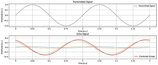
Figure 1.
Transmitted and received signal for a single frequency. The received signal is a sum of all the echoes.
The range R of the target is computed using:
where v represents the propagation speed of the signal. In air, this speed is approximately m/s.
The demodulated in-phase (I) and quadrature-phase (Q) baseband signals can be expressed as:
These signals are converted to digital form via an Analog-to-Digital Converter (ADC), where the phase encodes the range information of the target. By combining the digitized I and Q components, the received signals can be formulated into a complex representation:
Consequently, a complex vector V that contains the sequence of N stepped-frequencies is expressed as:
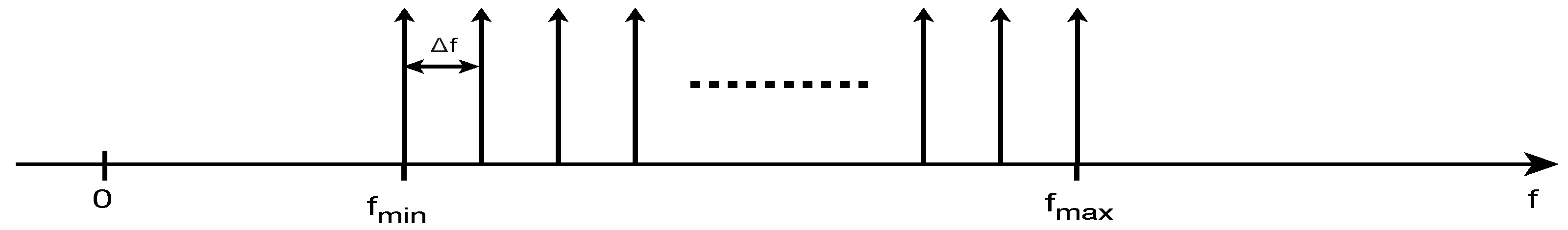
Applying the IDFT to a frequency-domain data array reconstructs a time-domain signal from its spectral components. Given an input array of length n, which contains complex-valued frequency-domain samples, the IFFT transforms these components into a sequence of real-valued time-domain samples with spacing. , where fs is the sampling frequency. The spectral components (Figure 2) in the input frequency-domain array are typically spaced by , with Nyquist frequency at .

Figure 2.
The spectrum data array, with a length of N, is acquired using an SFCW radar. The samples correspond to discrete frequencies spaced by within the closed frequency range from to .
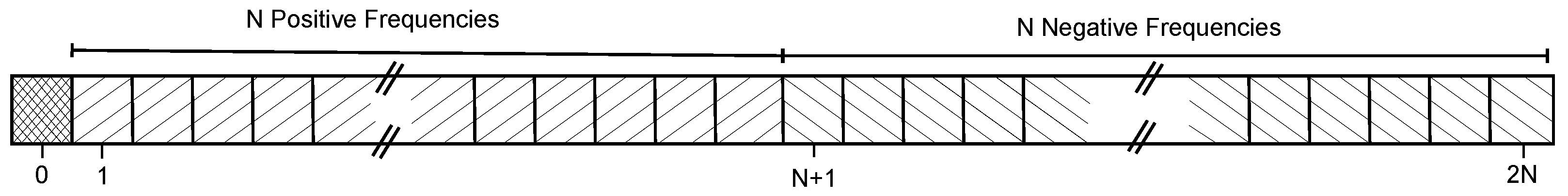
A symmetric frequency spectrum is typical for real-valued signals, where only the positive frequencies are explicitly stored, as the negative frequencies are their complex conjugates. By applying the IFFT to this structured frequency data, a time-domain representation of the signal is obtained, which can be used for further analysis or processing. Figure 3 shows the data structure of the complex frequency-domain input before transformation into the time domain. The array structure consists of a zero DC component, followed by raw frequency-domain samples, and then conjugated raw data arranged in reversed order. As a result, the extended data array and the corresponding time-domain array have a length of 2N + 1. A key characteristic of the unshifted IDFT is that the raw frequency-domain data samples are not aligned in a way that directly synchronizes with the appropriate frequency bins of the IFFT. This misalignment affects the spectral coherence of the reconstructed signal.
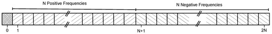
Figure 3.
The arrangement of the complex spectral data array when unshifted LPT on complex frequency domain samples. Adapted from Ref. [22]. Copyright © 2014, with permission from Elsevier.
3. Proposed Surface Reflection Suppression Method
The idea behind surface reflection suppression is to estimate the surface component for each individual frequency step, invert the phase, and couple it with the received echo at the receiver site of the radar. To model the surface reflection, we use the raw time-domain representation obtained from a prior reference measurement, which is obtained prior to each suppression instance. This is done by using a known procedure described in Section 2. No windowing functions are used before FFT, as this ensures that the raw characteristics of the signal remain intact and prevents distortions that could interfere with accurate surface reflection peak detection.
Surface reflection suppression is achieved using a reference-based approach. Before suppression, a reference measurement is acquired under identical conditions. This reference captures the dominant surface reflection response and is later used for suppression. The subsequent processing step, peak identification, suppression windowing, and phase compensation, are all performed on this reference signal. During actual data collection, the estimated surface reflection from the reference is used to synthesize a cancellation signal, which is then phase-aligned and subtracted from each received measurement at the radar’s front-end.
Once the time-domain signal is obtained, we transform the signal into absolute values specifically for peak extraction and then identify the signal peak corresponding to the surface reflection. The surface peak is typically the strongest reflection in the scene; however, we manually define the index of the first peak, which is then remembered and used as a starting point for locating the nearest peak in all subsequent range profile measurements. To account for the width of the surface reflection wavelet, we add an offset to the identified peak index. In our case, was experimentally determined to be 4, which encapsulates the entire surface reflection wavelet. This value is specific to our radar configuration, as the width of the impulse response in SFCW radars is determined by the inverse of the frequency bandwidth, which influences radar resolution. A different radar bandwidth would necessitate a different value to capture the surface reflection properly. The surface reflection peak index defines the window size of the signal to be subtracted in the frequency domain. The time-domain signal obtained from the reference measurement, used for suppression, is defined within the window , and the signal is then complex-zero padded to match the length of the original time-domain signal.
After defining the window for signal suppression, we perform FFT, which produces a symmetric spectrum with a known following structure:
- A zero DC component
- Positive frequency components
- Negative conjugate frequency components (arranged in reverse order)
From this data structure, we extract the positive frequency spectrum within the window (starting at one since a zero DC component is at 0), providing the frequency components for each individual frequency bin to be subtracted. The subtraction process involves shifting the phase of these components by 180°, and since we are in the frequency domain, this means multiplying the samples by −1, effectively canceling out the surface reflection.
Before the suppression signal is combined with the received signal, it must pass through system components, such as coaxial cables and a digital attenuator, which introduce additional delays and phase shifts. The path of the suppression signal before being coupled with the receiver antenna signal is comparable to the radar signal wavelengths and cannot be neglected. These system-induced effects change the phase of the generated cancellation signal and must be accounted for in the compensation process. To correct for this, we introduce a phase-correcting factor , which represents the phase shift caused by the radar system itself. This phase shift is measured beforehand through a calibration procedure, ensuring accurate compensation.
is determined by terminating the receiver port and running the entire measurement process with the transmitter and the surface reflection algorithm phase-synchronized. This allows us to isolate and measure the system-induced phase shift without external reflections.
The total compensated phase of the suppression signal is thus given by:
where represents the initially determined phase of the surface reflection, and accounts for additional delays introduced by the hardware.
The phase-compensated surface reflection component is then generated by an additional signal synthesizer at the receiver site and coupled with the received signal, effectively suppressing surface reflections before the signal is down-converted to an intermediate frequency (IF) and subsequently sampled.
This method is expected to be robust even when the surface is sloped, as long as the surface reflection peak is correctly identified. It is also computationally efficient and can be optimized for implementation in real-time processing, making it suitable for practical radar applications.
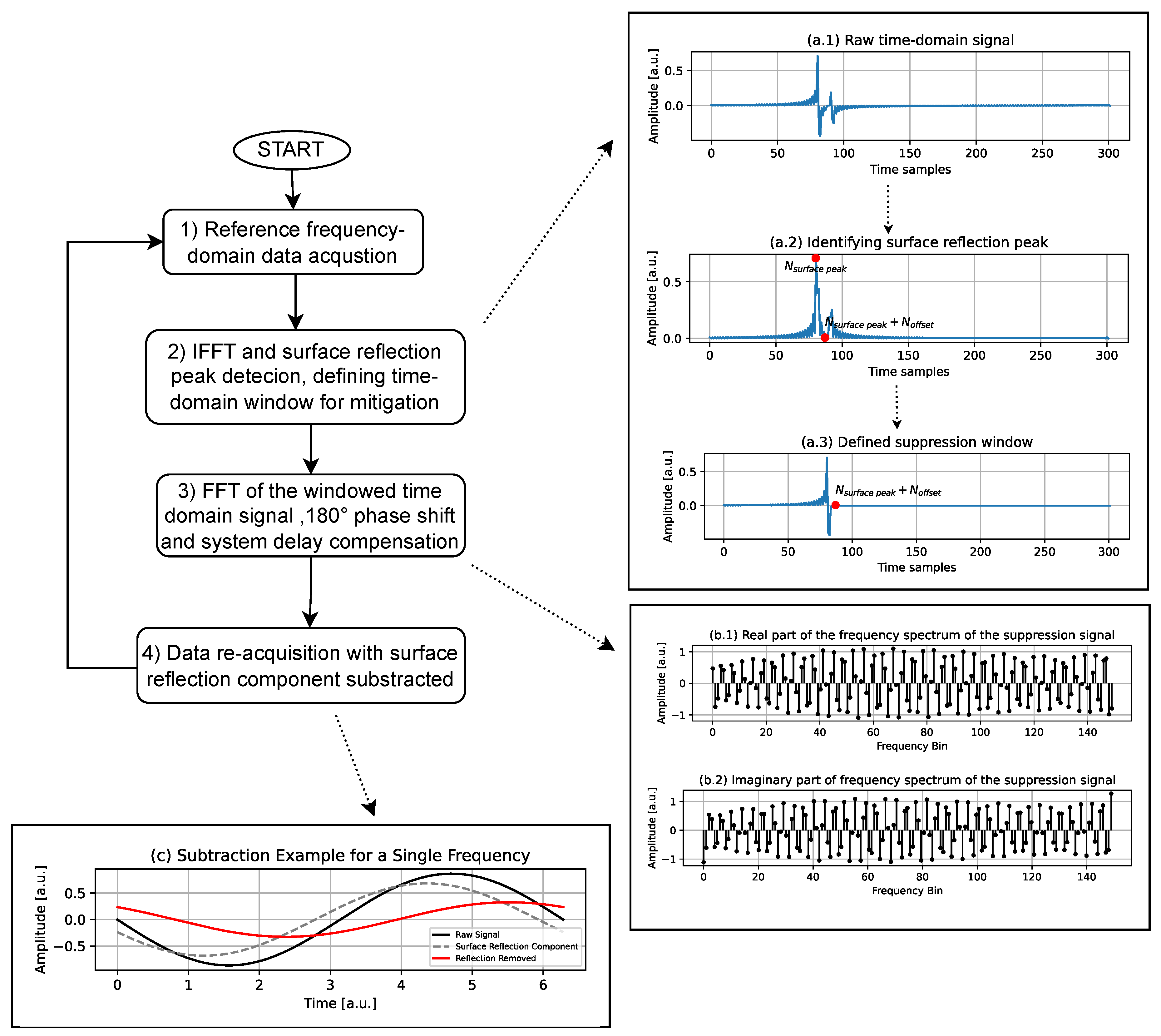
In Figure 4, this approach is presented step-by-step in a scenario where a single target is present beneath the surface.
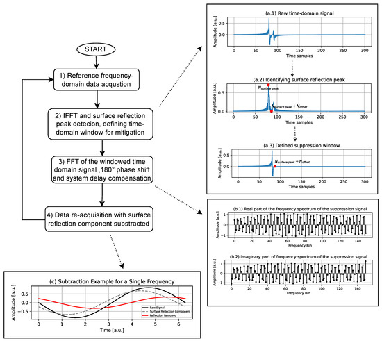
Figure 4.
Flow chart of the proposed method. The diagram illustrates the sequential steps for surface reflection component suppression, including reference reflection data acquisition, signal processing, and re-acquisition with the surface reflection suppressed.
The flowchart consists of four steps. The first step involves collecting the signal in the frequency domain. These raw data are then processed in the second step. Here, IFFT converts the frequency-domain data into the time domain, allowing for the detection of the surface reflection peak. A time-domain suppression window is then defined to suppress the surface reflection. In the third step, the previously windowed signal is transformed back into the frequency domain using FFT. A phase shift of 180° is applied to cancel out the surface reflection, while system delay compensation ensures proper alignment of the signals. Finally, in the fourth step, the processed data are reacquired with the surface reflection component removed.
The accompanying plots help visualize different stages of the process. The top-right plots, Figure 4a, show the identification of the surface reflection peak and the definition of the suppression window, which corresponds to step 2 in the flowchart. The middle-right plots in Figure 4b illustrate the frequency-domain representation of the signal, corresponding to step 3. These plots depict the spectrum of the signal that will be generated for surface reflection suppression. They represent the result of the FFT applied to the windowed signal after a 180° phase shift and system-induced phase correction. Based on this data, the amplitude and phase of the suppression signal are determined. Finally, the bottom-left plot, Figure 4c, demonstrates how the reflection is removed after processing, showcasing the received raw signal in black, the unshifted component for subtraction in dashed black, and the signal after the surface reflection component is subtracted in red, which is then sampled. The subtraction of each calculated surface reflection component is performed for every discrete frequency step in the radars’ bandwidth.
4. Radar Design
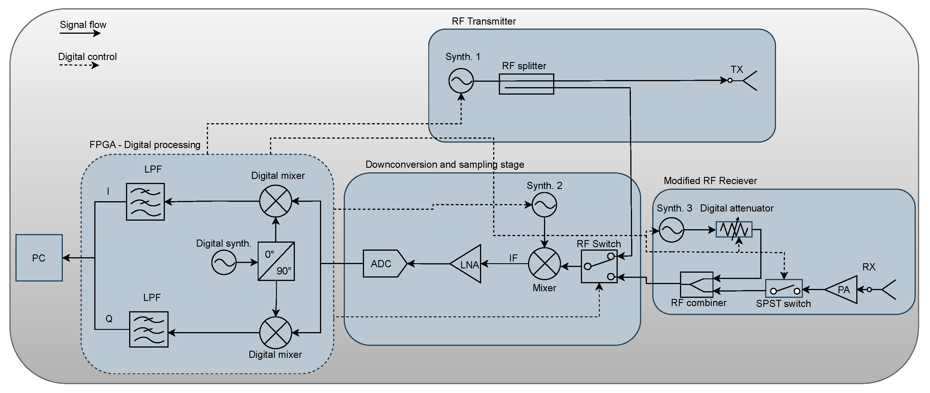
To test the surface reflection suppression method, we designed a modular SFCW radar based on a standard superheterodyne architecture. The block diagram of the system is shown in Figure 5, divided into four main sections: IQ demodulator, RF to IF band conversion stage, transmitter, and a slightly modified RF receiver, where an additional signal synthesizer and digital attenuator are added, which synthesize a suppression signal that is then combined with the received signal via an RF combiner. The entire system is controlled using an AMD Artix-7 35T Arty FPGA board. Conversion to complex IQ signals is implemented digitally. Additionally, a serial link is established between the FPGA and PC board for the continuous data stream, enabling further signal processing.
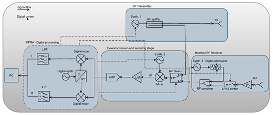
Figure 5.
Block diagram of the RF hardware system, showing the signal flow from the transmitter to the receiver, including digital processing, downconversion, and sampling stages.
While GPR radars typically utilize frequency bands below 1 GHz up to 2.5 GHz, the TI LMX2594PSEVM Evaluation Board, which is used for generating both the transmitting signal and the surface reflection suppression signal, could only achieve phase synchronization within a frequency range of 2.25 GHz to 3.74 GHz, with a step size of 10 MHz. The radar has a frequency step size of 10 MHz and a total of 150 frequency steps. These parameters determine the range resolution and maximum unambiguous range of the radar, which are 10 cm and 15 m, respectively. These key characteristics are calculated using the following equations:
where:
- c is the speed of light (propagation speed of radio waves),
- is the frequency step size,
- N is the number of frequency steps,
- represents the effective bandwidth of the SFCW radar.
The equations above describe how the range resolution () is inversely proportional to the total bandwidth, while the maximum unambiguous range () is determined by the frequency step size.
The IF is set at 2 MHz, with an IF sampling frequency of 10 MSa/s resolution at 14 bits, ensuring high-precision signal acquisition. The transmitter power is 0 dBm. The RF receiver gain is 30 dB, while the IF gain is 12 dB, improving the received signal strength for further processing. The system has an overall power consumption of 5 W, making it energy-efficient and suitable for battery-powered field applications. All these parameters, which define the operational capabilities of the SFCW radar, are summarized in Table 1.

Table 1.
System parameters, including frequency range, step size, gain, sampling rate, and power consumption specifications for the RF system.
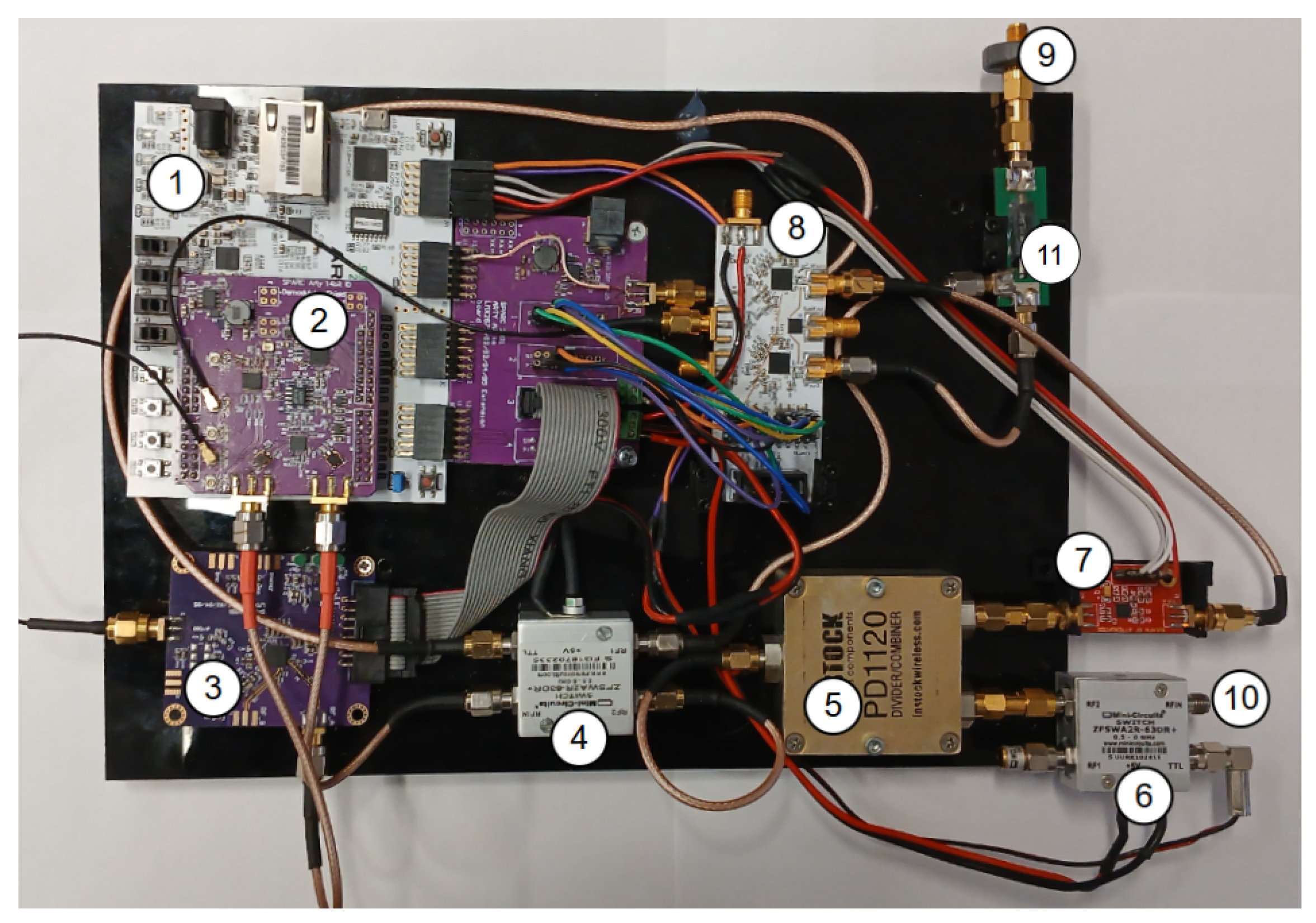
The system is depicted in Figure 6 and consists of multiple interconnected components essential for signal generation, transmission, reception, and processing. Table 2 lists and describes each numbered component in the image.

Figure 6.
Radar system hardware.
Table 2.
Component descriptions.
To enable surface reflection cancellation, we integrated an additional signal synthesizer (Synth. 3) into the RF receiver. This synthesizer offers phase synchronization and phase adjustment with the transmitting signal synthesizer (Synth. 1) and is specifically used to generate the surface reflection signal component for cancellation. For both Synth. 1 and Synth. 3, we utilized the Texas Instruments LMX2594PSEVM Evaluation Board, labeled as item 8 in Figure 6. While this chip also provides amplitude adjustment, the dynamic output range is limited to 10 dB (5 dBm to −5 dBm). To achieve lower amplitudes, an external digital attenuator was incorporated, offering an attenuation range of up to 30 dB in 1 dB steps. To achieve system time synchronization, the entire system is clocked by an external 10 MHz crystal oscillator, which directly serves as the reference signal for the ADC. The FPGA operates at a frequency of 100 MHz, which is derived from an external crystal oscillator using the Clocking Wizard IP core.
Additionally, a standalone LMX2594 board is employed as Synth. 2, which functions as a local oscillator of the superheterodyne receiver for signal downconversion. This component is shown as item 3 in Figure 6. The superheterodyne receiver architecture enables the demodulation of high-frequency signals into an IF band, which allows the signal to be sampled by a low-speed 14-bit ADC.
The RF switch at the receiver site is used to disable the antenna during the initial system-induced phase shift measurement described in Section 3.
5. Experimental Results
The experiment was designed to evaluate the effectiveness of the proposed surface reflection suppression method.
The experimental setup depicted in Figure 7, a schematic of which is depicted in Figure 8 with measurements, was arranged in a controlled environment to simulate realistic airborne GPR conditions. The key elements of the setup included:
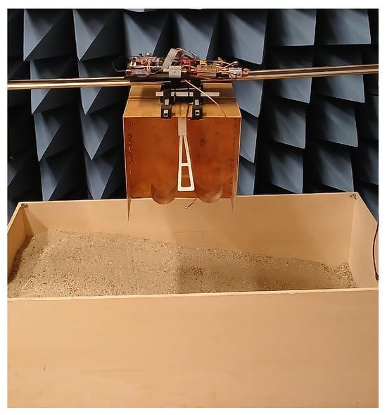
Figure 7.
Experimental setup illustrating the arrangement of equipment used for measurements.
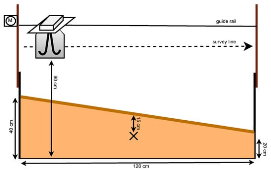
Figure 8.
Schematic representation of the experimental setup, depicting the survey line, guide rail, and measurement setup.
- Guide rail system: Ensured consistent and repeatable measurements along a predefined survey line.
- Radar system mounted at a fixed height: Positioned 80 cm above the ground, simulating airborne GPR operation.
- Synthetic target placed beneath the surface: Used to observe the impact of surface reflection suppression on buried target visibility. We used a trihedral corner reflector with a side length of 14 cm as the target, buried 15 cm deep and positioned at the midpoint along the sloped surface, 15 cm above ground level.
- Flat reflective surface: Introduced to generate strong surface echoes, which were then suppressed using the proposed algorithm. The test material was a mixture of sand (90%) and dirt (10%).
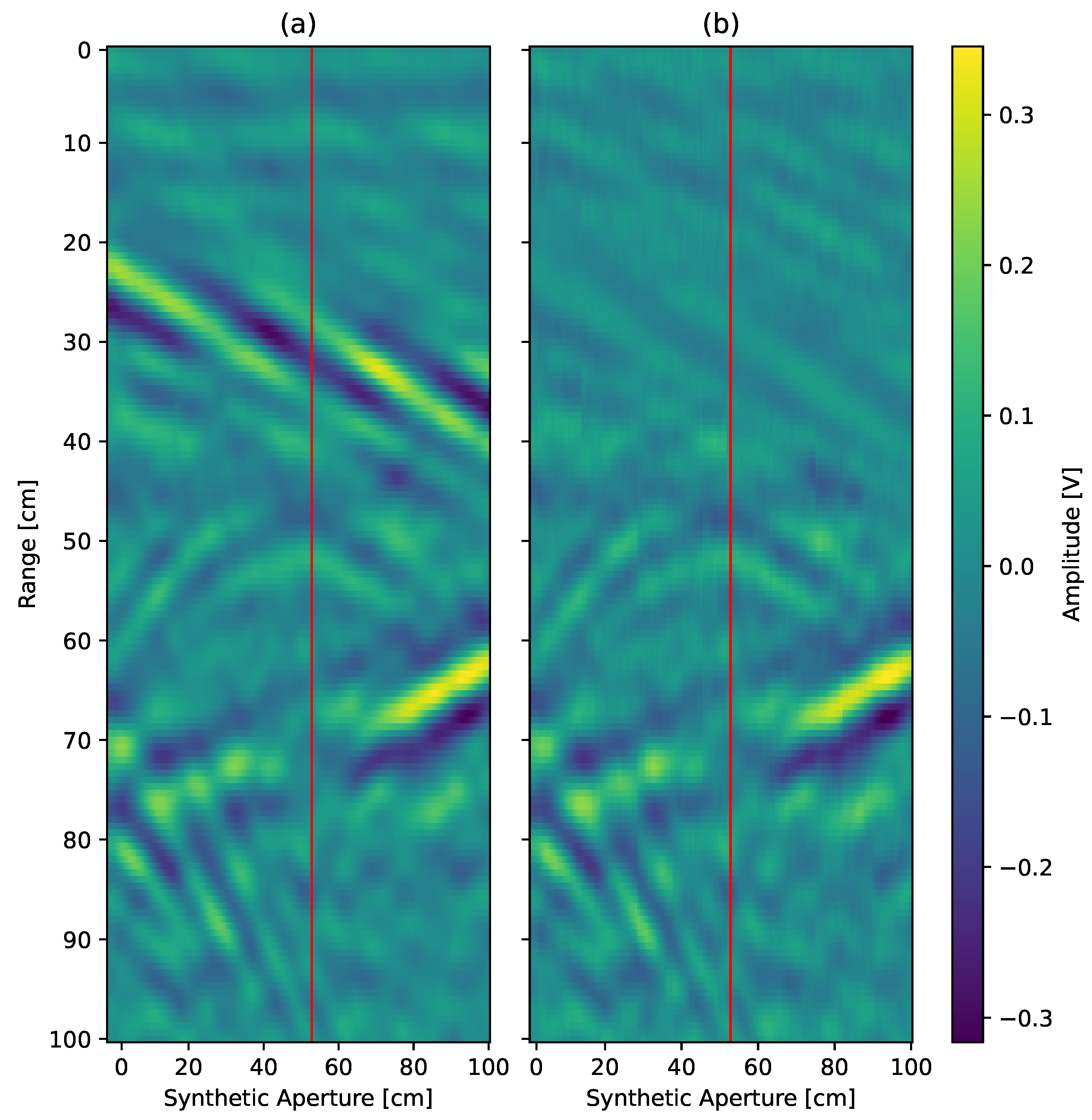
To assess the effectiveness of the suppression technique, B-scan images were generated from the acquired radar data. Figure 9a presents the raw B-scan image before suppression, showing a strong surface reflection with one target present, which is represented by the hyperbolic feature. After applying the suppression algorithm, Figure 9b reveals a significant reduction in surface reflection while maintaining the visibility of subsurface features. The floor reflection reconstruction in both images appears sloped due to the variation in the depth of the propagation medium, ranging from 40 cm to 20 cm. This slope is caused by the fact that electromagnetic waves travel slower through the sand mixture compared to air due to a higher dielectric constant. As a result, the reconstructed feature representing floor reflection is at an angle.
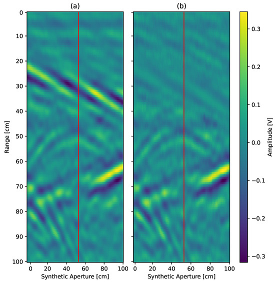
Figure 9.
(a) B-scan of the scene. (b) B-scan after applying the surface suppression algorithm. The red line indicates the selected trace used for further analysis. The horizontal axis represents the linear movement of the radar along the scan line, while the vertical axis indicates the depth relative to the radar, computed from signal delay using the propagation speed in air.
To further analyze the performance of the method, a selected A-scan was examined in the time domain. The time-domain trace discussed in the following section is marked with a red vertical line in Figure 9. The red vertical line corresponds to the central measurement point above the buried trihedral corner reflector, at the midpoint of the synthetic aperture. This position was chosen for its alignment with the target and is used for detailed A-scan evaluation in the following figures. Figure 10 displays the time-domain signal before and after suppression. The strongest reflection, corresponding to the surface echo, is noticeably reduced in amplitude after processing, allowing weaker reflections from subsurface targets to emerge more clearly. The gray waveform (without augmentation) shows a peak at the surface reflection point at around 15 ns, which is significantly attenuated in the red waveform (with the proposed method). This indicates a successful suppression of unwanted surface reflections. The signal corresponding to the target reflection at 16 ns remains prominent in both cases, which suggests that the proposed method effectively reduces only the surface reflections without significantly distorting the desired target response. The reduced interference from surface reflections enhances target detectability, improving signal clarity for further processing.
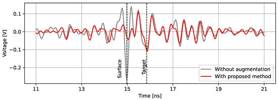
Figure 10.
Selected time-domain signal depicted before (gray) and after (red) the use of the proposed method, with identified key reflections.
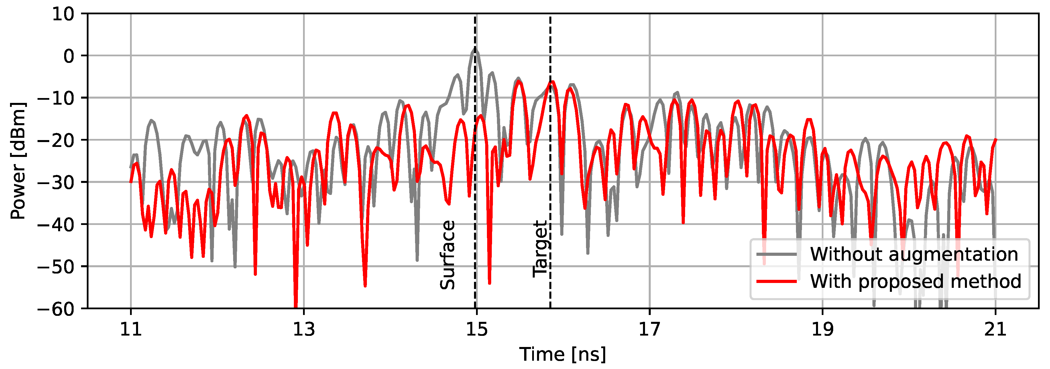
Figure 11 shows the time domain power response of the selected A-scan. Using the proposed method, we observe a significant drop in reflected power, from 1.8 dBm to −14.3 dBm. This corresponds to a total peak power reduction of 16.1 dB, suppressing unwanted surface reflections. The reduction in surface reflection improves the overall clarity of subsurface target detection, making the method particularly useful for applications requiring precise reflection separation.

Figure 11.
Selected time-domain power response depicted before (gray) and after (red) the use of proposed method, with identified key reflections.
5.1. Quantitative Evaluation of Signal Enhancement
We present quantitative metrics that objectively assess the performance of the proposed surface reflection suppression method. These metrics include the reduction in surface echo power, improvement in signal-to-clutter ratio (SCR), and changes in signal-to-noise ratio (SNR), all derived from the power response shown in Figure 11.
The most noticeable effect of the method is the suppression of surface reflections. From the measured power traces, we observe that the surface echo is reduced from 1.8 dBm in the unprocessed signal to −14.3 dBm after applying the proposed method. This corresponds to a total reduction in surface reflection power of:
which indicates significant attenuation of dominant clutter components.
To evaluate how effectively the target reflection is distinguished from clutter, primarily surface echoes, we compute the signal-to-clutter ratio, defined as:
In the processed signal, the target peak power is approximately −6.4 dBm, while the surface echo is around −14.3 dBm, giving an SCR of:
In the unprocessed signal, the target appears at −7.5 dBm and the surface reflection is at 1.8 dBm, resulting in:
The improvement in SCR is:
We also consider SNR, defined as:
Taking into account the noise floor of approximately −60 dBm, the SNR of the target peak after processing is:
and before processing:
This slight increase in SNR by 1.1 dB is not attributed to the proposed method and is likely due to variation in the measured signal.
Table 3 summarizes the results. The most notable benefit is the improvement in SCR by over 16.3 dB, which directly contributes to the enhanced isolation and detectability of subsurface targets.
Table 3.
Metrics before and after applying the proposed method.
5.2. Comparison with Existing Method
In this section, we compare the proposed surface reflection suppression method with an existing static echo cancellation approach. The primary distinction between the two methods lies in their adaptability to varying surface conditions and their effectiveness in airborne GPR applications.
The method proposed in [20] employs an integrated static target Echo Cancellation (EC) system designed for SFCW radar systems. This approach utilizes an additional RF synthesizer synchronized with the transmitter to generate a cancellation signal that mirrors the unwanted static reflection in amplitude but is 180° out of phase. This cancellation signal is then combined with the received echoes; the method effectively suppresses static reflections without altering the visibility of dynamic targets. The system assumes that the distance between the radar and the reflecting targets, which we want to cancel, remains constant throughout the measurement. This requirement, however, limits its effectiveness in air-coupled GPR applications, where the surface elevation fluctuates.
The method proposed in this paper introduces a phase-compensated subtraction technique specifically designed to address surface reflections in airborne SFCW GPR systems. Unlike the static EC approach, this method actively estimates the surface reflection component and applies a phase-adjusted subtraction at the receiver site. The advantage of this technique is its ability to compensate for ground elevation variations. By eliminating strong surface reflections before downconversion, the method improves the visibility of subsurface targets without requiring a high dynamic range receiver.
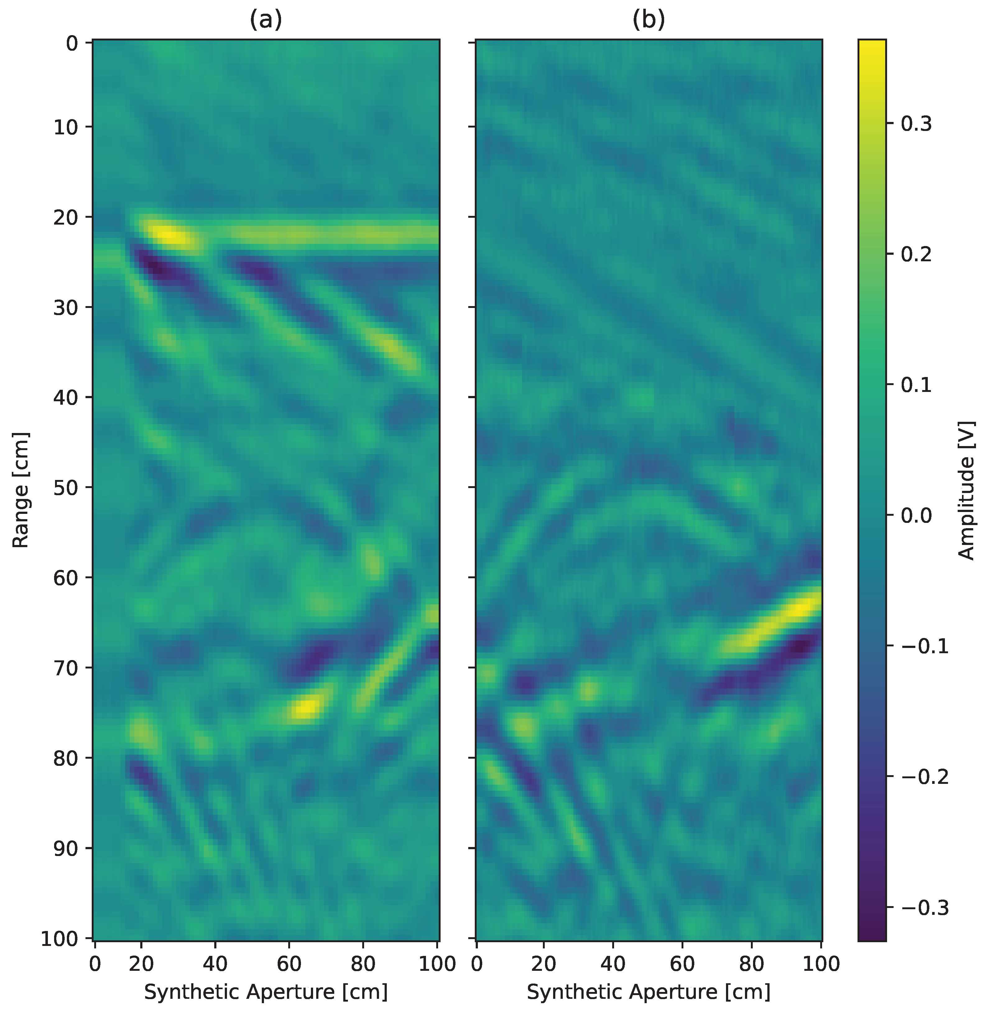
Figure 12 presents a comparison of the two methods, showing their effectiveness in surface reflection suppression. Figure 12a shows the performance of the static EC approach, where surface reflections remain visible due to the method’s reliance on a constant distance assumption between the radar and the canceled targets. This limitation results in incomplete suppression of unwanted echoes, particularly in airborne scenarios where terrain elevation varies. Additionally, in Figure 12a, the signal obtained during calibration for later subtraction becomes summed with the scene when the surface level changes. This results in the presence of a reflection that is not actually in the scene, which can be observed at the 20 cm mark throughout the entire synthetic aperture. By comparison, Figure 12b showcases the proposed phase-compensated subtraction method, which dynamically adapts to changes in surface elevation and achieves significantly better suppression of surface reflections.

Figure 12.
Comparison of surface echo suppression methods: (a) Static echo canceling approach, which does not account for ground fluctuations, and (b) the surface reflection suppression method proposed in this paper.
The results show that while the static EC algorithm is useful for stationary environments, it struggles in scenarios where surface deviations are present. The proposed method outperforms the static EC approach, thus making it a more suitable solution for airborne SFCW GPR systems.
6. Discussion
The experimental results demonstrate that the proposed algorithm significantly reduces ground surface reflections while maintaining subsurface target visibility.
The algorithm’s processing simplicity makes it suitable for real-time implementation. Certain hardware-induced phase shifts must be calibrated beforehand to ensure optimal performance. Future implementations could integrate adaptive filtering techniques to adjust phase correction parameters dynamically.
While the method effectively reduces surface reflections, its performance may be influenced by:
- Varying surface roughness: The algorithm assumes a relatively smooth surface for reflection estimation. Uneven terrain could introduce phase variations, requiring further compensation.
- Environmental factors: Changes in surface material properties (e.g., moisture content) could alter reflection characteristics, necessitating adaptive calibration methods.
Current method effectively suppresses surface reflections under relatively consistent conditions; future work will focus on extending its robustness to rough or variable surfaces. This includes simulation-based evaluation of terrain distortion effects and the design of adaptive suppression strategies capable of updating the reference dynamically or estimating local surface behavior from sequential measurements. Future versions will incorporate environmental sensing data to help anticipate changes in signal behavior due to varying dielectric properties of the surface material.
Future work will also examine the robustness of the algorithm under varying noise levels and SNR conditions. While the current study did not include a detailed noise analysis due to equipment constraints and project scope, this aspect is critical for validating real-world performance. Experiments will involve controlled noise injection to quantitatively assess the algorithm’s performance and define operational thresholds across different SNR conditions.
Current setup assumes low altitude airborne conditions, where antenna to surface distance varies from 40 to 60 cm typical for close proximity ground applications, such as landmine detection [14], where good air-to-ground coupling is desired and surface reflection dominates in the received signal.
At higher altitudes, the dominant signal may shift from surface reflection to antenna coupling. In such scenarios, suppressing surface echoes may be unnecessary or even counterproductive. Surface echoes can serve as reference points for interpreting the depth of subsurface reflections. However, our goal in mitigating is not to eliminate useful information but to allow for more efficient energy transfer toward subsurface features. The suppression method we propose is therefore best suited for applications in which the surface echo dominates the signal, such as low-altitude surveys or scenarios where the radar must remain contactless, such as scanning architectural surfaces or heritage structures where direct contact is not allowed.
Currently, the entire process of sampling the data, performing time-domain analysis, identifying the surface reflection peak, calculating the spectrum for subtraction, and then re-sampling the data with the surface reflection component subtracted at each frequency bin takes approximately 1 s per scan. This processing time significantly limits the speed of operation if the system were to be mounted on a moving platform, such as a drone. As a result, the current system is primarily suitable for controlled laboratory environments rather than real-time field deployment.
The primary bottleneck in the system is the calibration speed of the PLL-based voltage-controlled oscillator (VCO), which operates in fractional mode. The frequency settling time for a single frequency bin is approximately 800 µs, and for the entire spectrum of 150 frequency bins, this results in a total tuning time of approximately 0.12 s per spectrum acquisition. Since two full acquisitions are required—one for reference data acquisition and another for the surface reflection-suppressed signal—the total frequency tuning overhead doubles to 0.24 s per measurement cycle. However, this calibration speed could potentially be improved by using the Full Assist Mode, which is supported by the Texas Instruments LMX2594 chip. This mode allows for faster frequency settling by leveraging pre-calibrated settings, reducing calibration latency.
In addition to the VCO limitation, the overall processing time could be significantly improved by migrating the time-domain analysis and peak detection onto the FPGA instead of performing these operations on a separate PC. Currently, Python 3.11.7-based libraries are used for time-domain analysis, introducing additional latency due to data transmission between the FPGA and the PC. By implementing these computations directly on the FPGA, the need for real-time data streaming could be eliminated, thereby reducing the overall processing time and making the system more viable for real-time applications.
7. Conclusions
The proposed algorithm effectively suppresses surface reflections by estimating and subtracting the reflection component at the receiver site while maintaining subsurface target visibility, validating the method’s effectiveness. Through both B-scan and A-scan analyses, the method was shown to significantly suppress dominant surface reflections while maintaining the visibility of desired subsurface targets. A peak surface reflection power reduction of 16.1 dB was observed, and the SCR improved from −9.3 dB to +7.0 dB, indicating a total change of 16.3 dB. The SNR was also marginally improved, demonstrating that the method does not compromise the signal integrity of subsurface targets.
Future work includes integrating this approach with automatic gain control, which is expected to enhance the radar’s penetration depth while maintaining signal integrity with a static input ADC. Additionally, efforts will focus on implementing the algorithm for real-time operation exclusively on an FPGA board, reducing the need for external computation on a PC and eliminating the requirement for a serial data link between the PC and the FPGA board.
The developed approach provides a promising solution for suppressing surface reflections in air-coupled GPR systems, contributing to enhanced signal processing techniques for subsurface exploration.
Author Contributions
Conceptualization, P.S. and D.G.; methodology, P.S.; software, P.S.; validation, P.S.; formal analysis, P.S.; investigation, P.S.; resources, D.G.; data curation, P.S.; writing—original draft preparation, P.S.; writing—review and editing, D.G.; visualization, P.S.; supervision, D.G.; project administration, D.G.; funding acquisition, D.G. All authors have read and agreed to the published version of the manuscript.
Funding
This research was funded by the Slovenian Research and Innovation Agency (ARIS) through Research Programme P2-0065, the Young Researchers Programme and ARIS J2-50072 project.
Data Availability Statement
The original contributions presented in this study are included in the article. Further inquiries can be directed to the corresponding author.
Conflicts of Interest
The authors declare no conflict of interest.
Abbreviations
The following abbreviations are used in this manuscript:
| GPR | Ground Penetrating Radar |
| CW | Continuous Wave |
| SFCW | Stepped Frequency Continuous Wave |
| TWIR | Through-Wall Imaging Radar |
| EC | Echo Cancellation |
| ADC | Analog-to-Digital |
| LPT | Lowpass Transformation |
| LNA | Low Noise Amplifier |
| LPF | Low Pass Filter |
| PLL | Phase-Locked Loop |
| FFT | Fast Fourier Transform |
| IDFT | Inverse Discrete Fourier Transform |
| IF | Intermediate Frequency |
| FPGA | Field Programmable Gate Array |
| VCO | Voltage-Controlled oscillator |
| SNR | Signal-to-Noise Ratio |
| SCR | Signal-to-Clutter Ratio |
References
- Rasol, M.; Pais, J.C.; Pérez-Gracia, V.; Solla, M.; Fernandes, F.M.; Fontul, S.; Ayala-Cabrera, D.; Schmidt, F.; Assadollahi, H. GPR monitoring for road transport infrastructure: A systematic review and machine learning insights. Constr. Build. Mater. 2022, 324, 126686. [Google Scholar] [CrossRef]
- Koohmishi, M.; Kaewunruen, S.; Chang, L.; Guo, Y. Advancing railway track health monitoring: Integrating GPR, InSAR and machine learning for enhanced asset management. Autom. Constr. 2024, 162, 105378. [Google Scholar] [CrossRef]
- Colica, E.; Antonazzo, A.; Auriemma, R.; Coluccia, L.; Catapano, I.; Ludeno, G.; D’Amico, S.; Persico, R. GPR Investigation at the Archaeological Site of Le Cesine, Lecce, Italy. Information 2021, 12, 412. [Google Scholar] [CrossRef]
- Thomas, S.B.; Subbaraj, S.; Sona, D.R.; Thomas, B. Non-destructive GPR signal processing technique for thickness estimation of pavement, coal and ice layers: A review. J. Appl. Geophys. 2025, 233, 105601. [Google Scholar] [CrossRef]
- Pi, S.; Wang, T.; Lin, J. Directional and High-Gain Ultra-Wideband Bow-Tie Antenna for Ground-Penetrating Radar Applications. Remote Sens. 2023, 15, 3522. [Google Scholar] [CrossRef]
- Pryshchenko, O.A.; Plakhtii, V.; Dumin, O.M.; Pochanin, G.P.; Ruban, V.P.; Capineri, L.; Crawford, F. Implementation of an Artificial Intelligence Approach to GPR Systems for Landmine Detection. Remote Sens. 2022, 14, 4421. [Google Scholar] [CrossRef]
- Núñez-Nieto, X.; Solla, M.; Gómez-Pérez, P.; Lorenzo, H. GPR Signal Characterization for Automated Landmine and UXO Detection Based on Machine Learning Techniques. Remote Sens. 2014, 6, 9729–9748. [Google Scholar] [CrossRef]
- Garcia-Fernandez, M.; Alvarez-Lopez, Y.; Las Heras, F. Autonomous Airborne 3D SAR Imaging System for Subsurface Sensing: UWB-GPR on Board a UAV for Landmine and IED Detection. Remote Sens. 2019, 11, 2357. [Google Scholar] [CrossRef]
- Singh, V.; Kumar, S.; Kumar, A.; Singh, A.K. A Review on Impulse RADAR. Int. J. Electron. Telecommun. 2021, 67, 579–587. [Google Scholar]
- Wang, G.; Xiong, R. Design of Impulse Ground Penetrating Radar Signal Source Based on Power Synthesis. In Proceedings of the 2024 43rd Chinese Control Conference (CCC), Kunming, China, 28–31 July 2024; pp. 3357–3361. [Google Scholar] [CrossRef]
- Solla, M.; Novo, A.; Elseicy, A.; Prego, F.J. Rebar detection: Comparison of stepped frequency continuous wave and pulsed GPR. Procedia Struct. Integr. 2024, 64, 293–300. [Google Scholar] [CrossRef]
- Kong, F.N.; By, T.L. Performance of a GPR system which uses step frequency signals. J. Appl. Geophys. 1995, 33, 15–26. [Google Scholar] [CrossRef]
- Sugak, V.G.; Sugak, A.V. Phase Spectrum of Signals in Ground-Penetrating Radar Applications. IEEE Trans. Geosci. Remote Sens. 2010, 48, 1760–1767. [Google Scholar] [CrossRef]
- Šipoš, D.; Gleich, D. A Lightweight and Low-Power UAV-Borne Ground Penetrating Radar Design for Landmine Detection. Sensors 2020, 20, 2234. [Google Scholar] [CrossRef]
- Li, W.; Zhao, Z.; Tang, J.; He, F.; Li, Y.; Xiao, H. Performance Analysis and Optimal Design of the Adaptive Interference Cancellation System. IEEE Trans. Electromagn. Compat. 2013, 55, 1068–1075. [Google Scholar] [CrossRef]
- Monteiro, D.; Marques, G.; Silva, D.; Casaleiro, J.; Costa, V. An Active Self-Interference Cancellation Front-end for Stepped-Frequency Continuous-Wave Radar. In Proceedings of the 2024 8th International Young Engineers Forum on Electrical and Computer Engineering (YEF-ECE), Lisbon, Portugal, 5 July 2024; pp. 116–120. [Google Scholar] [CrossRef]
- Zhang, J.; He, F.; Li, W.; Li, Y.; Wang, Q.; Ge, S.; Xing, J.; Liu, H.; Li, Y.; Meng, J. Self-Interference Cancellation: A Comprehensive Review from Circuits and Fields Perspectives. Electronics 2022, 11, 172. [Google Scholar] [CrossRef]
- Li, Y.; Dang, P.; Xu, X.; Lei, J. Deep Learning for Improved Subsurface Imaging: Enhancing GPR Clutter Removal Performance Using Contextual Feature Fusion and Enhanced Spatial Attention. Remote Sens. 2023, 15, 1729. [Google Scholar] [CrossRef]
- Li, C.; Ma, Q.; Wang, Y.; Yang, X.; Liu, H.; Wang, L. Suppression of Multiple Reflection Interference Signals in GPR Images Caused by Rebar Using VAE-GAN. Appl. Sci. 2025, 15, 3728. [Google Scholar] [CrossRef]
- Šipoš, D.; Gleich, D. SFCW Radar with an Integrated Static Target Echo Cancellation System. Sensors 2021, 21, 5829. [Google Scholar] [CrossRef] [PubMed]
- Nguyen, C.; Park, J. Stepped-Frequency Radar Sensors: Theory, Analysis and Design; SpringerBriefs in Electrical and Computer Engineering; Springer International Publishing: Cham, Switzerland, 2016. [Google Scholar] [CrossRef]
- Seyfried, D.; Schoebel, J. Stepped-frequency radar signal processing. J. Appl. Geophys. 2015, 112, 42–51. [Google Scholar] [CrossRef]


Disclaimer/Publisher’s Note: The statements, opinions and data contained in all publications are solely those of the individual author(s) and contributor(s) and not of MDPI and/or the editor(s). MDPI and/or the editor(s) disclaim responsibility for any injury to people or property resulting from any ideas, methods, instructions or products referred to in the content. |
© 2025 by the authors. Licensee MDPI, Basel, Switzerland. This article is an open access article distributed under the terms and conditions of the Creative Commons Attribution (CC BY) license (https://creativecommons.org/licenses/by/4.0/).