Article

Vision-Based Mid-Air Object Detection and Avoidance Approach for Small Unmanned Aerial Vehicles with Deep Learning and Risk Assessment

Department of Aeronautics and Aeronautics, National Cheng Kung University, Tainan 701, Taiwan
*
Author to whom correspondence should be addressed.
Remote Sens. 2024, 16(5), 756; https://doi.org/10.3390/rs16050756
Submission received: 8 December 2023 / Revised: 14 February 2024 / Accepted: 19 February 2024 / Published: 21 February 2024

Abstract

:
With the increasing demand for unmanned aerial vehicles (UAVs), the number of UAVs in the airspace and the risk of mid-air collisions caused by UAVs are increasing. Therefore, detect and avoid (DAA) technology for UAVs has become a crucial element for mid-air collision avoidance. This study presents a collision avoidance approach for UAVs equipped with a monocular camera to detect small fixed-wing intruders. The proposed system can detect any size of UAV over a long range. The development process consists of three phases: long-distance object detection, object region estimation, and collision risk assessment and collision avoidance. For long-distance object detection, an optical flow-based background subtraction method is utilized to detect an intruder far away from the host. A mask region-based convolutional neural network (Mask R-CNN) model is trained to estimate the region of the intruder in the image. Finally, the collision risk assessment adopts the area expansion rate and bearing angle of the intruder in the images to conduct mid-air collision avoidance based on visual flight rules (VFRs) and conflict areas. The proposed collision avoidance approach is verified by both simulations and experiments. The results show that the system can successfully detect different sizes of fixed-wing intruders, estimate their regions, and assess the risk of collision at least 10 s in advance before the expected collision would happen.

1. Introduction

In recent years, more and more companies have begun utilizing drones for many applications because of their high flexibility and adaptability to various environments. As the demand for UAVs has gradually increased, the collision problem between UAVs has also risen. To regulate UAVs’ uncontrolled operations in the airspace, the Federal Aviation Administration (FAA) has proposed a flight information sharing specification called remote identification (RID) [1]. Besides Remote ID, FAA, NASA, and other federal partner agencies have also proposed the concept of unmanned aircraft system traffic management (UTM) [2], since the development of UAV logistics has led to the density of UAVs in low-altitude airspace increasing. To prevent the risk of mid-air collisions, detect and avoid (DAA) is one of the essential technologies of UTM, which ensures the safety of beyond-visual-line-of-sight flight operations.

1.1. Airborne Sensing Technologies and Collision Avoidance Strategies for UAVs

The main concept of DAA is constructed by approaching time instead of distance because time is more suitable to express the approaching speed of the intruder than distance. Considering the reactivity of the pilot and the maneuverability of the UAV, the requirement of DAA in UTM should be triggered at least 10 s before a collision occurs to ensure minimum safety separation. The FAA proposed the Pathfinder project to further regulate the specifications beyond the current small UAV rules [3]. In the Pathfinder project report, a safety regulation for the commercial use of a small UAV was mentioned. According to the rules of the FAA’s project, a terrestrial acoustic sensor array (TASA) was developed to sense obstacles from 5 nm away and over a full 360° field of view [4]. However, the main purpose of this study is to prevent small UAVs from colliding with each other. Therefore, acoustic sensors are too heavy and large for small UAVs.
To avoid intruder aircrafts that may pose a potential threat, sensing technologies are necessary for advanced preparation. According to how the information is transmitted, sensing technologies for DAA can be classified into two categories: cooperative and noncooperative [5,6]. The sensors utilized in cooperative methods include vehicle-to-vehicle communication, automatic dependent surveillance broadcast (ADS-B), and RID. Noncooperative sensors include airborne radars, light detection and ranging (LiDAR) sensors, acoustic sensors, and cameras. However, considering the payload capacity of small UAVs, most of the sensors mentioned above are too large and heavy to be mounted on UAVs. Moreover, the cost of some sensors is not affordable compared to the price of the UAV itself. Therefore, a camera becomes an ideal sensor for UAVs to detect interesting objects and targets. A monocular camera has many advantages, such as its light weight, low cost, the fact that it is easy to equip, and it is also widely used in different applications. However, depth information cannot easily and directly be obtained with a monocular camera.
After an intruder is detected by a sensor, the avoidance maneuver is necessary to keep the intruder at a safe distance. For DAA systems in UAVs, there are two processes: decision making and avoidance control. Decision making is based on object detection and object tracking. Once an object is identified as an intruder, an avoidance maneuver is triggered. There are two categories of avoidance control: planning avoidance [7,8,9,10,11,12] and reactive avoidance [13,14,15]. Generally, planning avoidance methods are usually utilized by cooperative DAA systems, such as artificial potential fields (APFs) [12], trajectory generation [7], and path planning [10]. Most of these methods calculate a global solution for avoiding obstacles in the environment. Some of the planning avoidance methods utilize deep learning models to further optimize the solution [11]. On the other hand, reactive avoidance is more passive than planning avoidance. It controls the host aircraft based on the current state and solves the collision through local motion control. One planning avoidance method utilizes nonlinear model predictive control (NMPC) to avoid an intruder with a single vision sensor [16]. Another study [17] utilized a doppler radar to implement collision avoidance. Since the sensor in our study is a camera, reactive avoidance is more appropriate for the proposed DAA system.

1.2. Vision-Based Object Detection with Deep Learning Technology

With the help of deep learning technology, a vision-based DAA was proposed to determine collision avoidance strategies only using vision information and to detect the distance between a predefined intruder and the host in a previous study [18]. To conduct collision avoidance, the object detection method and avoidance strategy are the two major processes used to reduce the collision risk of UAVs. With the advantages of computer vision and artificial intelligence (AI) technologies, vision-based object detection methods have been studied for many decades and applied in many applications. In recent years, there have been many studies focused on UAV detection with vision-based methods and deep learning [19,20,21,22,23]. For instance, the you only look once (YOLO) method is a fast and powerful object detection method which is applied to various subjects [24,25,26,27].
Most studies on the object detection of UAVs are focused on ground or static targets [26]. There are still many challenges in moving object detection, especially for mid-air and fixed-wing UAVs [28]. Compared to multirotor UAVs, fixed-wing UAVs have higher aerodynamic efficiency and performance, can carry more payload, and can travel longer distances. However, the restrictions of fixed-wing UAVs are that they must move forward at a desired airspeed and cannot perform hovering or move in any direction. For mid-air vision-based object detection, Lai et al. proposed a multi-stage pipeline of a single-vision-based UAV DAA process [18]. The main purpose of this work was to detect an incoming fixed-wing UAV in the image and estimate its distance using deep learning methods. YOLOv3 was utilized in the study to detect the incoming UAV in the image, and the results were passed through deep learning methods to estimate the distance between the incoming UAV and the host. Although the result is accurate over a short range, there are still some limitations to the study. The distance estimation model is sensitive to the size of the target; that is, the estimation error would increase if the size of the target UAV was different from the one used in the study. In addition, the detection range of this study is not long enough to meet the requirements of UTM. Apart from deep learning methods, some vision-based object detection methods utilize optical flow to detect moving objects in an image. In one study [29], an optical-flow-based background subtraction algorithm is applied to detect moving objects with a single vision. With the background model constructed with the Lucas–Kanade optical flow algorithm, the background subtracted image between two consecutive frames can be estimated. Consequently, moving objects, also known as the foreground, will be highlighted. Even though the detection range in this approach is long enough for the DAA process, there are still some drawbacks that must be overcome. One of them is the interference of background noises, which causes failure in detecting and tracking expected objects. Thus, this approach is combined with a Kalman filter to improve the performance of object detection in this study.

1.3. Vision-Based Reactive Avoidance Methods for UAVs

For a monocular camera system, the avoidance strategy is based on the relative angle and relative size of the intruder in the image. In one study [30], a single vision-based DAA algorithm was utilized for an unmanned surface vehicle (USV) system. In this study, a camera mounted on the USV was used to sense intruder USVs in the field of view (FOV). The area and motion of an intruder USV in the image were then utilized to assess the risk of collision. Unlike UAVs, USVs can only move on a two-dimensional plane. Therefore, there are sufficient constraints to derive the relative position of a USV intruder in an image. However, the dynamic motion of UAVs is more complex than that of USVs, as UAVs move in three-dimensional space. The relative position of the UAV intruder should be obtained in other ways, or other information in the image should be used to assess the risk.
Lyu et al. proposed another collision avoidance strategy for UAVs, which was only based on a dynamic safety envelope [31]. The dynamic safety envelope was constructed by the motion and position of the intruder in the image. The avoidance maneuver was then implemented by visual servo control, which aims to keep the central point of the image away from the dynamic safety envelope. This approach overcame the lack of depth information limitations but ignored some special cases. In another study [32], the concept of the time to closest point of approach (TTC) was utilized by a single-vision collision avoidance system. The TTC is estimated by the relative size expansion ratio in the proposed approach. However, the estimation of the TTC is most accurate in the center of the image. Misestimations of the TTC may lead to wrong avoidance timing. Cichella et al. proposed a relative-angle-based collision avoidance method for UAVs [33]. The line of sight (LOS) represents the angle between the velocity vector of the host aircraft and the distance vector from the intruder. The LOS rate controls the host aircraft to avoid an intruder. The proposed method in the study [23] successfully kept the intruder at a certain LOS and maintained the minimum distance within the safety range. The LOS is presented in the form of coordinates in the image in this study.
The goal of this study is to improve the performance of the developed DAA and meet the requirements of UTM. The contributions of this study are listed as follows:
(1)
A comprehensive procedure for the mid-air collision avoidance approach based on the determination of the collision risk for fixed-wing UAVs is proposed by using a monocular camera.
(2)
The proposed DAA does not require the sizes of the intruders or the exact distance between an intruder and the host UAV to train the deep learning model.
(3)
The DAA could be triggered 10 s or earlier before a collision happened. Therefore, to ensure a sufficient reaction time, the sensing range of this study must be larger than 10 s before the fixed-wing intruder reaches the host UAV.
(4)
Flight tests were conducted to demonstrate long-range object detection and collect data for the risk-based collision avoidance method.
(5)
A collision avoidance strategy is proposed and evaluated in the simulations to verify the developed avoidance strategy with the proposed collision risk assessment, which is determined by the area expansion rate and bearing angle of the intruder in the images.
The remainder of this study is organized as follows: Section 1 presents related works regarding vision-based object detection and reactive avoidance. A long-range vision-based object detection method is introduced in Section 2. This section also covers a deep-learning-based object area estimation method, including the Mask R-CNN model architecture, the process for training the model, and the detection results of the custom training model. Section 3 presents the risk assessment based on the relative information in the image and defines the composition of the collision risk. The evaluation results of the simulations and flight experiments are provided in Section 4. The proposed method is verified in this section. Finally, the conclusion and future works are presented in Section 5.

2. Vision-Based Long-Range UAV Detection with Deep Learning Technology

The main purposes of this study are to detect UAVs that are approaching the host aircraft as far away as possible and to assess the collision risk of an intruder UAV with only vision information. First, an optical-flow-based background subtraction method is utilized to detect long-range UAVs, which can highlight the areas that contain moving objects in an image. Those areas will be cropped into smaller images for further calculations. Then, the level of collision risk is determined by analyzing the location of the intruder UAV and the area occupied by it in the image plane. The proposed collision risk assessment is carried out, which is determined by the area expansion rate and bearing angle of the intruder in the images. The area of the intruder UAV is estimated by an instance segmentation structure called a Mask R-CNN. This section presents the processes of detecting long-range objects and estimating their area with a Mask R-CNN. A flow chart of the UAV sensing system is shown in Figure 1.

2.1. Long Distance Object Detection

In this study, the definition of long distance is the distance that a fixed-wing intruder UAV can fly within 10 s or more. Generally, long-distance objects look like tiny dots in an image. In this case, the deep-learning-based method will not detect them successfully as the target is too small to identify. An optical-flow-based background subtraction method is utilized to detect moving objects in the image. The process of long-distance object detection is shown in Figure 2. First, a set of feature points is extracted by corner detection. Afterward, the Lucas–Kanade optical flow algorithm uses background subtraction to detect the moving objects in the image. In addition, a two-dimensional Kalman filter is utilized to track the object in the image.

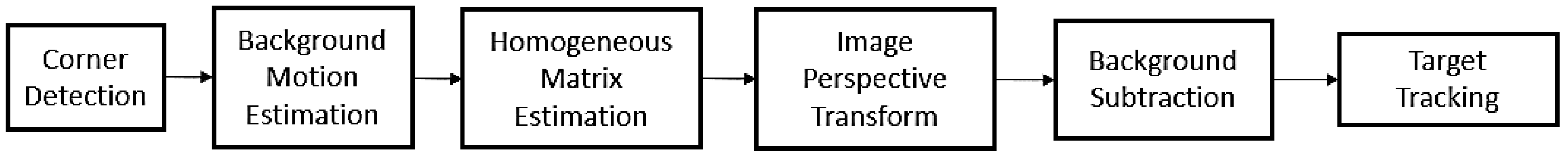
2.1.1. Homogeneous Matrix Estimation and Image Perspective Transform

In this study, Shi–Tomasi corner detection is used to detect a set of salient points, p. To ensure that the salient points are more evenly distributed in the image, they are re-detected every few frames. Furthermore, the image is divided into left and right parts, and their respective salient points are detected separately to guarantee a uniform distribution of these points. The Lucas–Kanade method is then utilized to estimate the local motion of each salient point.
With the local motion of the salient points, the global transformation matrix, H t , can be fitted by the least-squares method, as follows [29]:
H t = argmin H p t P t , p t 1 P t 1 p t H · p t 1 2
where Pt and Pt−1 are the sets of salient points in the current frame of the image, It, and the previous frame of the image, It−1, respectively. More detail on the global transformation matrix, H t , can be found in [29].
The perspective transform model is chosen as the intruder UAV occupies a tiny area in the image. After the homogeneous matrix is determined, a perspective transform is applied to the image in the previous frame, It−1, to establish the background model of the image in the current frame, It.

2.1.2. Background Subtraction and Object Detection

With the established background model of the current image, the background subtracted image is computed to capture the moving objects whose motions are considerably different from the background motion. Although most of the background is subtracted, some unexpected noises in the background-subtracted image are still present due to the uneven distribution of the salient points or complex background motion. Therefore, two processes are applied to reduce the noise. The first one is image post-processing. Two morphological operations are applied to highlight the exact targets: top-hat and black-hat. Both operations are used to extract tiny elements and details from the input images. The former is used to enhance brighter features in the image. In contrast, the latter is used to enhance darker features in the image. The output filters the background-subtracted image and reduces most of the background noise. The second process is object tracking with a Kalman filter. A two-dimensional linear Kalman filter is utilized to smooth the data and track the object in the image. The estimated states are the position and velocity of the detected object on the 2D image plane. A Kalman filter can estimate the state of a dynamic system from a series of measurements that contain uncertainty.

2.2. Object Area Estimation

A deep-learning-based UAV area estimation method is utilized to assess the risk of the intruder UAV in the image frames. The absolute distance from the camera or host UAV to the intruder UAV is not necessary. The main technology explored in this section is called instance segmentation, which implements object detection and semantic segmentation simultaneously. A Mask R-CNN is chosen as the detector, which not only detects the object but also calculates the area (mask) of the object. Upon successful object detection through background subtraction, the region of interest (ROI) containing the intruder UAV is cropped from the original image. Next, the ROI is input to the custom-trained Mask R-CNN detector to estimate the area. In addition, the process of training the custom Mask R-CNN model is provided in this section.

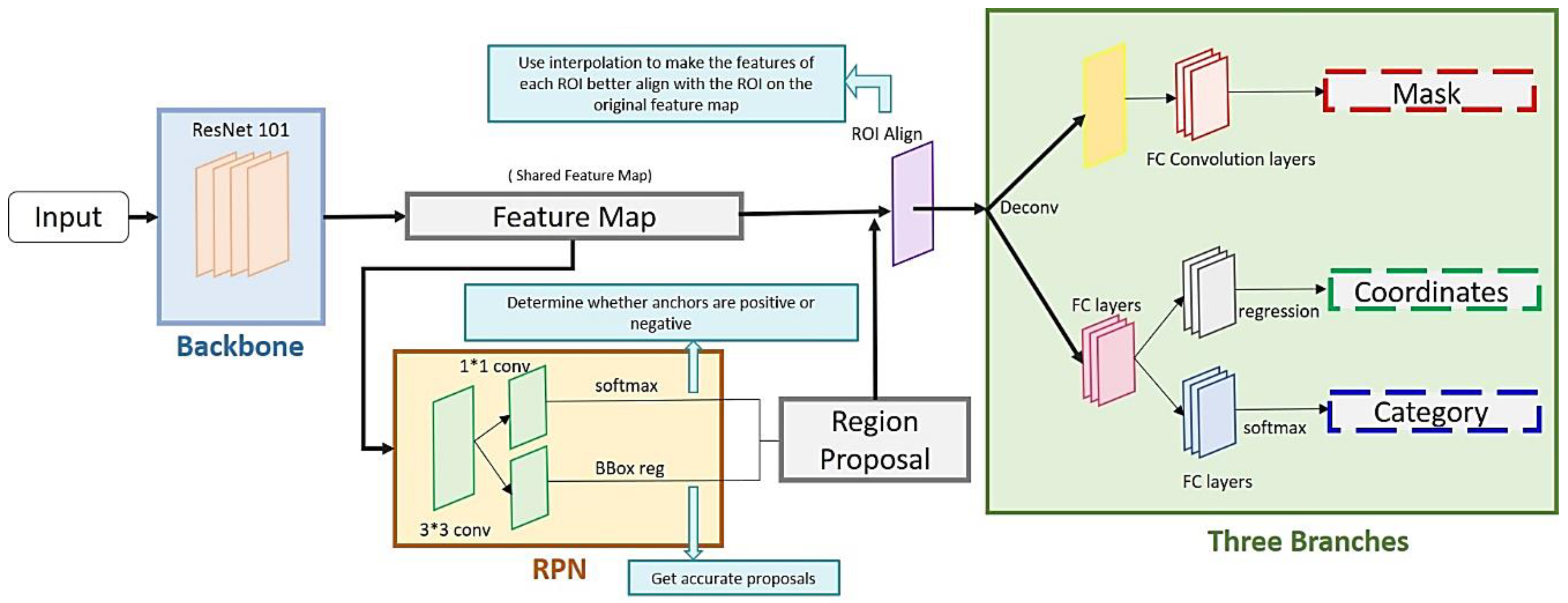
2.2.1. Mask R-CNN Detector

Object detectors can be classified into two main categories: one-stage detectors and two-stage detectors. The R-CNN series belongs to two-stage detectors, which have higher accuracy in recognizing objects than one-stage detectors like YOLO and SSD. However, two-stage detectors consume more computational resources and time. In this study, a Mask R-CNN [34] is employed as an object detector to estimate the area occupied by the intruder UAV in the image for the following reasons:
(1)
Compared to the previous version of R-CNNs, Mask R-CNNs added a new output: the mask, which represents the area of the object.
(2)
As a two-stage detector, a Mask R-CNN has relatively high accuracy in object instance segmentation.
The architecture of a Mask R-CNN is illustrated in Figure 3, which is mostly the same as the structure of a Faster R-CNN. The only difference is that a Mask R-CNN has an additional output called the mask [34]. The architecture consists of two stages. The first stage generates proposals that might contain objects by scanning the image, and the second stage arranges the proposals and generates bounding boxes, masks, and classes of the objects. In this study, ResNet101 is selected as the backbone CNN because its deeper structure allows for better recognition of smaller objects, which is essential for the needs of this research. More details about the architecture and parameters of Mask R-CNNs can be found in the studies [34,35].

2.2.2. Training Process

This section provides the process of training the custom Mask R-CNN model, including dataset collection, data labeling, and the training process. There are many open-source image datasets on the internet, such as Microsoft Common Objects in Context (MS COCO) [36], Cifar-10, and ImageNet [37]. Each of them has a wide variety of classes and sufficient data. However, image datasets that focus on fixed-wing UAVs are not available. In other words, it is necessary to collect a custom dataset to carry out object detection on fixed-wing UAVs. A real-flight UAV image dataset and synthetic images that contain UAVs were collected for training purposes. The software used to generate the images is Blender 2.8 [38], which is a powerful 3D graphic processing software. It has various applications, such as animation and game making and image and video rendering. 1python code and Blender software were combined to generate numerous UAV images with different attitudes automatically. This study ended up collecting a dataset with 1000 UAV images. The UAVs’ roll, pitch, and yaw angles range between ±15, ±15, and ±75 degrees, respectively. The attitude specifications of the UAVs in the images and the image information are listed in Table 1.
After the dataset collection was completed, the next step was image labeling. The dataset was divided into two subsets, training and validation data, in a 7:3 ratio. In this study, MakeSense.ai was chosen as the image-labeling tool as it is an open-source and online tool. Therefore, it does not consume local resources while labeling the images. In contrast to object detection, instance segmentation was implemented. Consequently, the labels are polygons instead of rectangles. In this study, a custom Mask R-CNN model was trained with the pre-trained weight of the MS COCO dataset. The model is trained for 50 epochs with 100 training steps per epoch, resulting in a final loss of about 0.9. The mean average precision (mAP) at epoch 50 is 0.98. It took about 2.5 h to train the model with a NVIDIA GeForce GTX 1660 GPU card (TSMC, Hsinchu, Taiwan).

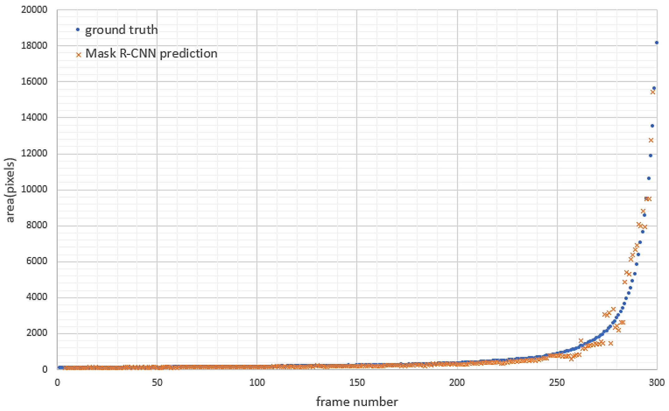
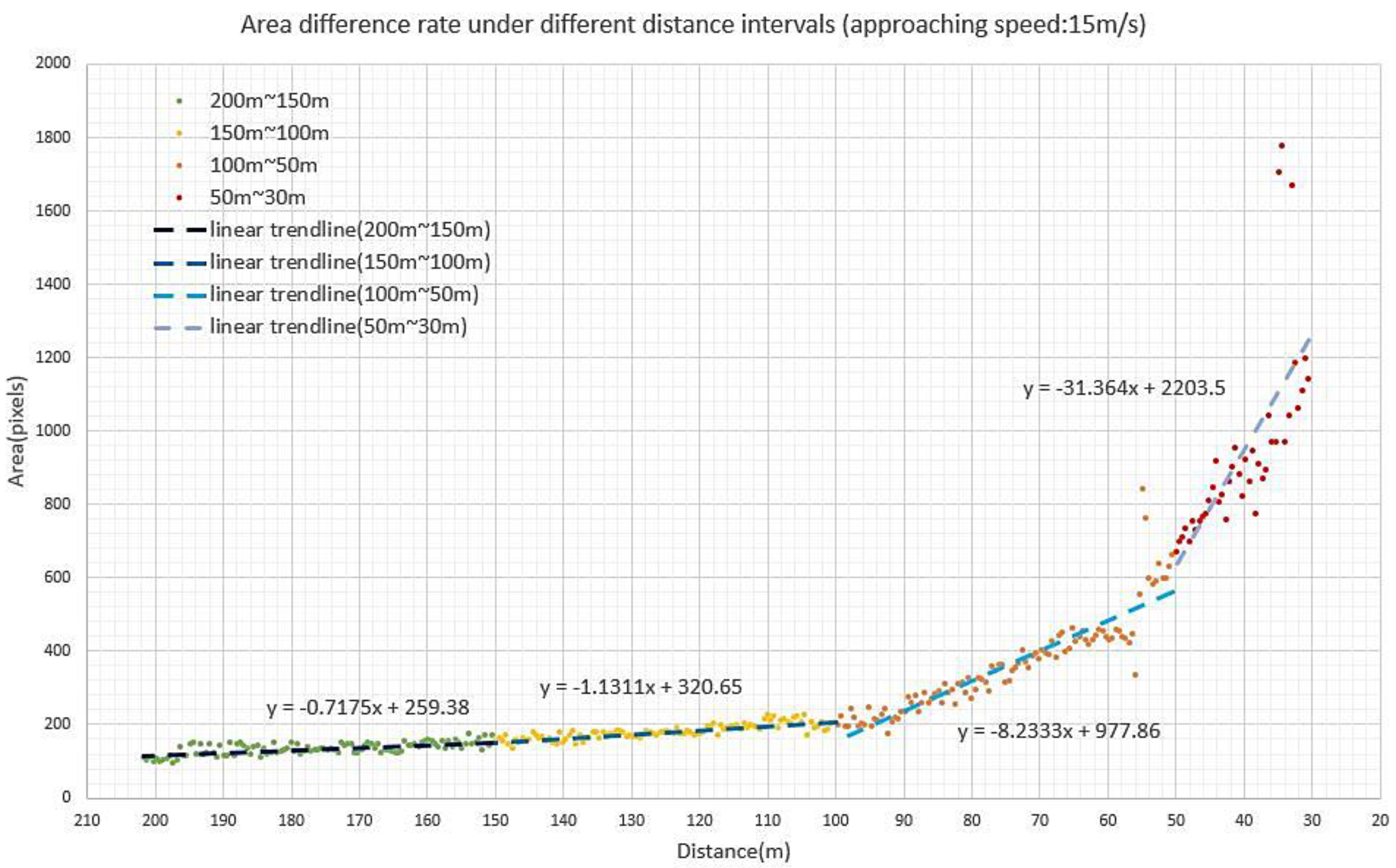
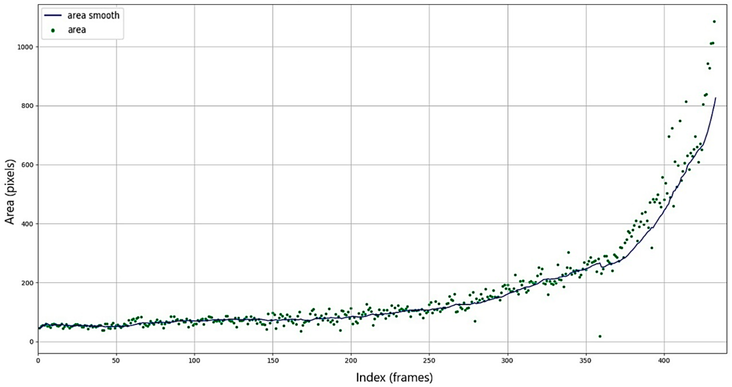
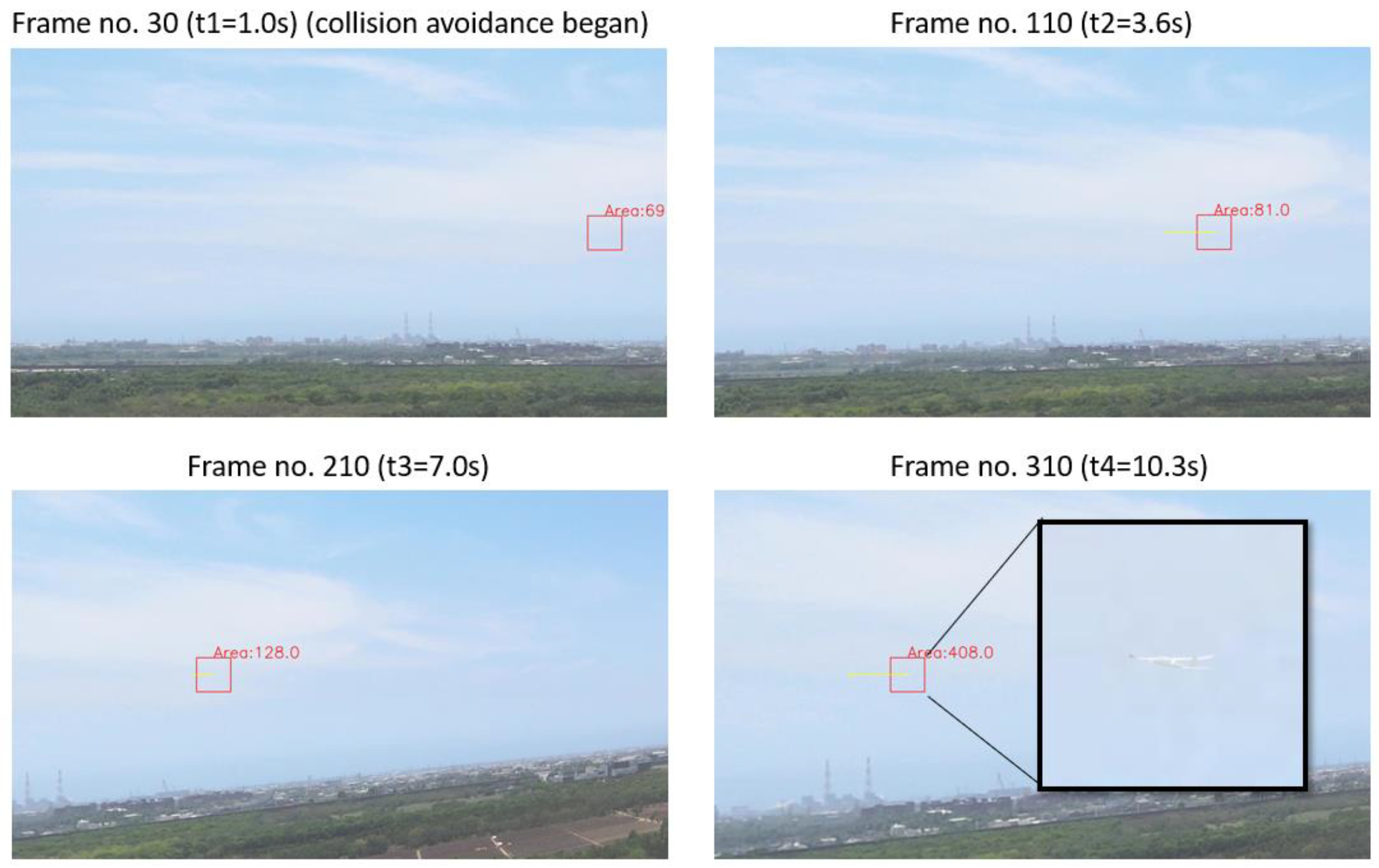
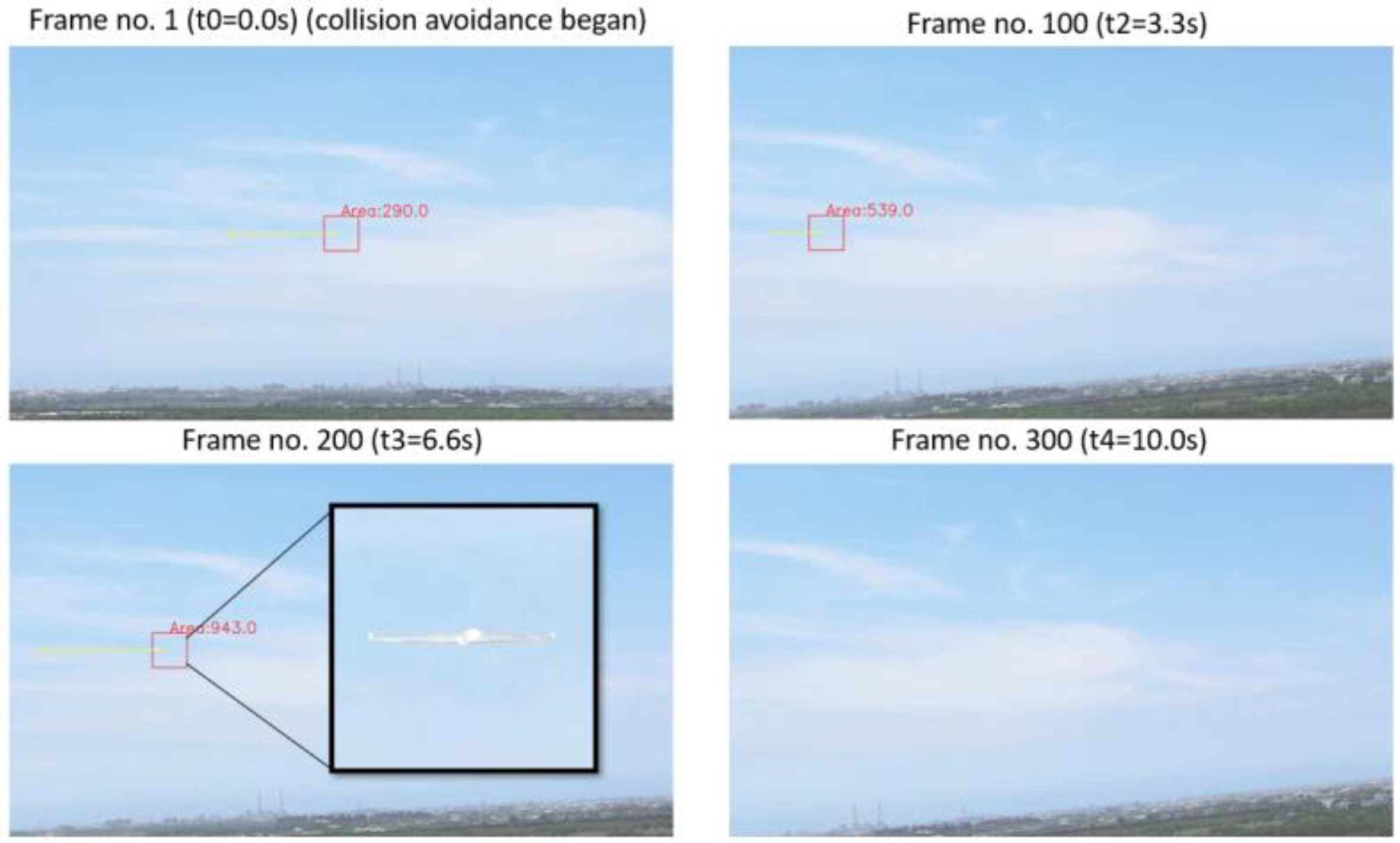
2.2.3. Object Area Detection Results

The detection results of the custom Mask R-CNN model are shown in Figure 4 and Figure 5. Figure 4 shows the detection results for synthetic images generated by Blender. The background is also detected and displayed in orange. Figure 5 shows the detection result in real-flight videos. Most of them have successfully detected the position and mask of the UAV. Besides detecting the UAV in the images, the pixel-wise accuracy of the model was also evaluated using synthetic videos. The ground truth of the area was extracted by HSV thresholding. For the convenience of HSV thresholding, the background of the video was simplified to a single color. The scenario in the synthetic video is shown in Figure 6, where the distance is from 200 m to 10 m. The results are shown in Figure 7, where the pixel-wise percentage accuracy is 87.89%. In addition to evaluating the mask accuracy, the relation between different approaching speeds and the area estimation curve is also provided in Figure 8. As Figure 9 shows, the slope of the area difference rate increases as the distance between the host and UAV intruder decreases.

3. Collision Risk and Avoidance Strategy

In this section, a two-dimensional image-based risk assessment of mid-air UAV collision avoidance is proposed. Since a monocular camera is chosen as the only sensor in this research, it would be difficult to capture depth information directly. Therefore, only the information shown in the image is utilized to achieve a collision risk assessment of mid-air collisions. The coordinates and the area of the intruder were estimated in the previous section. In addition, the moving direction of the intruder is estimated by the intruder’s positions between two consecutive frames. These estimations are utilized to analyze the potential threat of intruders and to detect the collision risk.

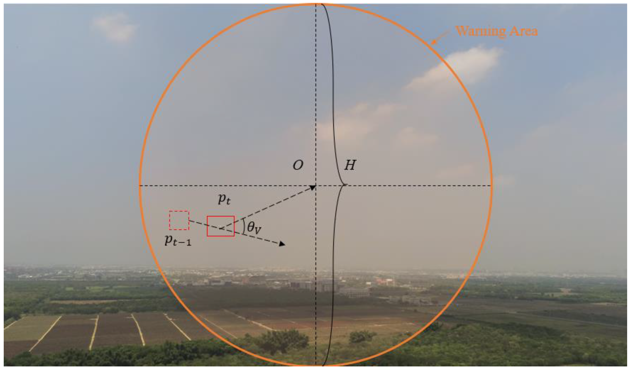
3.1. Proposed Collision Risk

The collision risk of an approaching UAV is constructed by three parts: (1) the area expansion factor, (2) the position factor, and (3) the bearing factor. Since all the information received is based on the two-dimensional image plane, the specific time to the closest point of approach (TTC) or distance to the closest point of approach (DCPA) cannot be estimated. Instead, a relative collision risk between the host aircraft and the intruder is defined in this study. Those three factors mentioned above are distributed by different weights. The collision risk is presented as follows:
R i s k t o t a l = w a R i s k a + w p R i s k p o s i t i o n + w b R i s k b e a r i n g
where R i s k a is the area expansion factor, R i s k p o s i t i o n is the position factor, R i s k b e a r i n g is the bearing factor, and w a , w p , and w o are their weightings ( w a + w p + w o = 1 ). R i s k a , R i s k p o s i t i o n , and R i s k b e a r i n g are nondimensional parameters.
The area of the intruder in the video is continuous data. The connection between collision risk and the area expansion factor is based on the expansion rate of the area. In [30], the area difference of the USV between two consecutive frames is directly utilized to assess the probability of collision. However, the area difference is close to zero or floating near zero when the object is at a certain distance. Secondly, the area estimation uncertainty would lead to a false result. Consequently, the area difference is replaced by the area expansion rate to assess the risk of approaching the object, and the definition of the area expansion factor is listed as follows:
R i s k a = ( a t a 0 ) a 0 2 + ( a t a 0 ) 2
where a t is the intruder’s area in the current frame, and a 0 is the intruder’s area in the frame that the intruder is first detected in. The position factor of the collision risk is defined by 2D coordinates. The definition of the position factor is listed as follows:
R i s k p o s i t i o n = 0 ,   i f   p t O > H / 2 H / 2 p t O H / 2 ,   i f   p t O < H / 2
where p t is the coordinate of the intruder in the current frame, H is the height of the image, and O is the center of the image. An illustration of the position factor is shown in Figure 10, where the orange circle represents the warning area. From a three-dimensional perspective, the warning area becomes a cone. Objects inside the cone range are threatening to the host aircraft. The position factor increases as the distance between the intruder and the center decreases.
The final part of collision risk concerns the intruder’s moving direction, which is also called the bearing factor. The moving direction of the intruder is defined by the vector composed of the intruder’s positions between two consecutive frames. The definition of the bearing factor is listed as follows:
R i s k b e a r i n g = 0 ,   i f   90 ° < θ V < 180 ° cos θ V ,   i f   0 < θ V < 90 °
cos θ V = p t 1 O · p t 1 p t p t 1 O p t 1 p t
where p t 1 is the coordinate of the intruder in the previous frame. An illustration of the bearing factor is shown in Figure 10. If θ V is an acute angle, the intruder is flying toward the center of the frame. On the contrary, if θ V is an obtuse angle, the intruder is flying away from the center of the frame.

3.2. Collision Avoidance Strategy Based on Collision Risk

In this study, the selected collision scenario is the UAV logistics of fixed-wing UAVs in low-altitude airspace. Since the low-altitude airspace for drone delivery is assumed to use the same flight level, this study aims to use only the horizontal rotation direction in the avoidance analysis and experiment. For the avoidance maneuvers, we consider the flight dynamics of fixed-wing UAVs, such as the attitude change and the yawing rate constraints of the fixed-wing UAVs. Considering the maneuverability of this kind of UAV, the collision avoidance rules only concern horizontal turning action. The principle of avoidance follows visual flight rules (VFRs). Situations with a potential threat of collision are illustrated in Figure 11, where the dashed lines represent the original paths of the UAVs, and the solid lines represent the avoidance paths of the UAVs. This research only considers crossing and head-on cases.
The scenario in this study is that the host aircraft is conducting waypoint following while an intruder appears in the FOV of the camera. Therefore, after assessing the collision risk of the intruder, the collision avoidance system gives avoidance control to the host aircraft based on the collision risk. The host continuously assesses the risk while avoiding the intruder to keep the intruder away from the safety range. The conflict areas of both UAVs determine the potential collision hazard. If the conflict areas of the two UAVs overlap, these two UAVs are defined as potential collision hazards. The conflict area is defined as a sector centered on the UAV’s velocity vector with a range of 6 degrees. The formation of the conflict area is shown in Figure 12.
The assumptions made about UAV maneuvers are listed as follows:
  • The host aircraft must have an initial velocity as shown in Equation (7). If the host aircraft hovers at a fixed point, the avoiding maneuver will not affect the host aircraft.
    0 < V h o s t
  • The angular velocity of the host aircraft has an upper bound (Equation (8)) to limit the avoidance maneuver to a reasonable range.
    θ ˙ h o s t < θ ˙ m a x
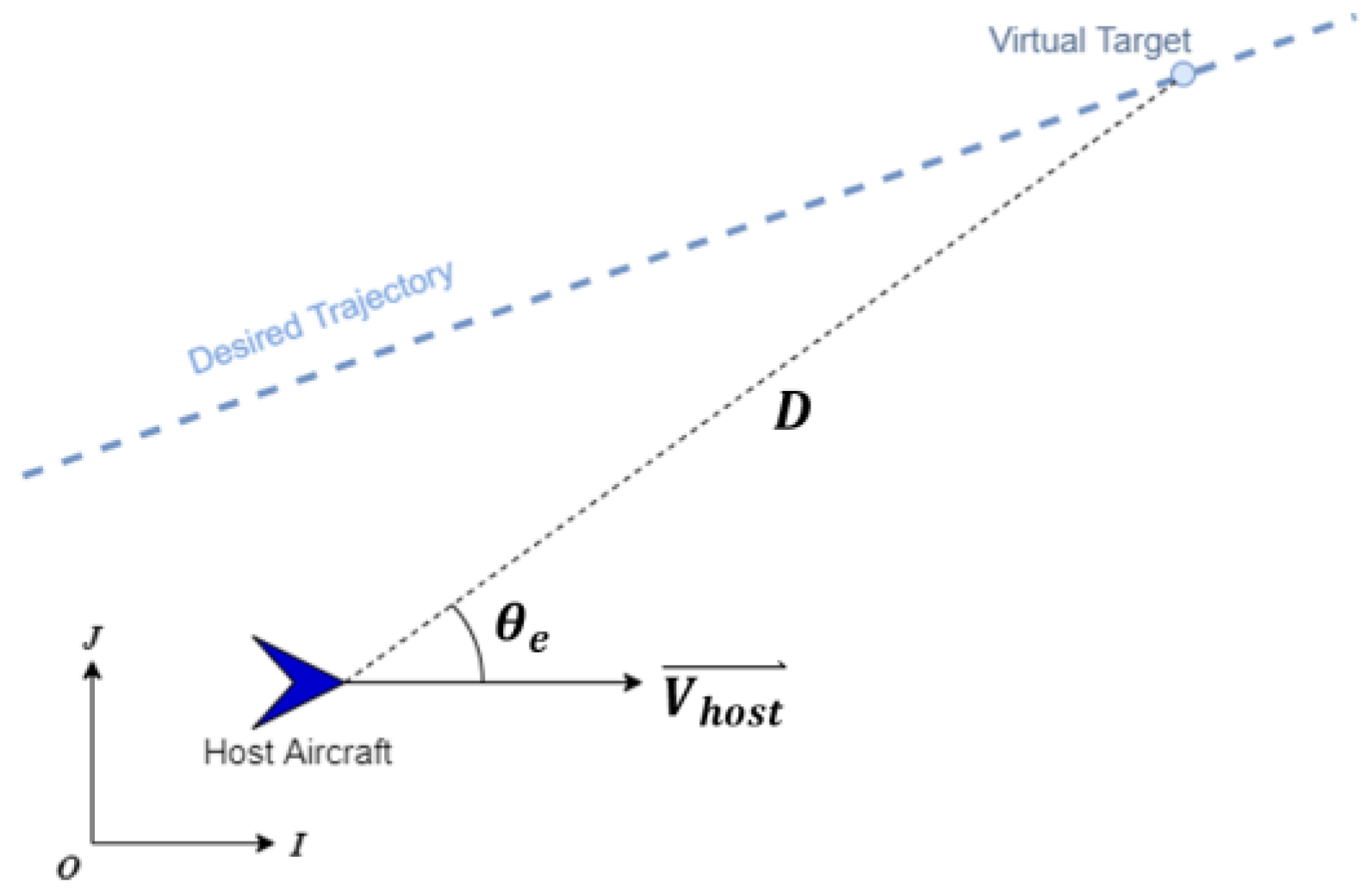
  • The control law refers to [33], which is composed of waypoint following, θ ˙ t r , and collision avoidance, θ ˙ c a , as shown in Equation (9). In Equation (10), k t r is the proportional gain of the waypoint following command. As shown in Equation (10) and Figure 13, θ ˙ t r is controlled by a waypoint following controller modified from [32], and D is the distance between the virtual target and the host aircraft.
    θ ˙ h o s t = θ ˙ t r + θ ˙ c a
    θ ˙ t r = k t r s i n θ e   ( r a d / s )
  • The proposed collision avoidance system aims to reduce the collision risk and ensure the minimum TTC between the intruder and the host aircraft.
  • The avoidance maneuver intensity is another crucial factor to be concerned about. The intensity is equal to the angular velocity. The value of collision risk determines the avoidance intensity, and the function is defined as follows:
    θ ˙ c a = π 2 R i s k total   ( rad / s )
  • Equation (11) is also modified from the study [32]. When the intruder UAV is determined by the collision risk, we force the host UAV to travel in a direction perpendicular to the position of the intruder UAV with respect to the host UAV. R i s k t o t a l is the weighting to adjust the value of θ ˙ c a . If the collision risk of the intruder exceeds 0.5, the avoidance maneuver will remain the same for 1 s.

4. Simulation and Flight Experiment Results

To verify the proposed mid-air collision avoidance approach, simulations and real flight tests were conducted to evaluate the performance of the long-range object detection and collision avoidance strategies. Long-range object detection and area estimation are evaluated by real-flight experiments. To reduce the incidence of aircraft accidents, the proposed collision avoidance strategy is evaluated through simulations.

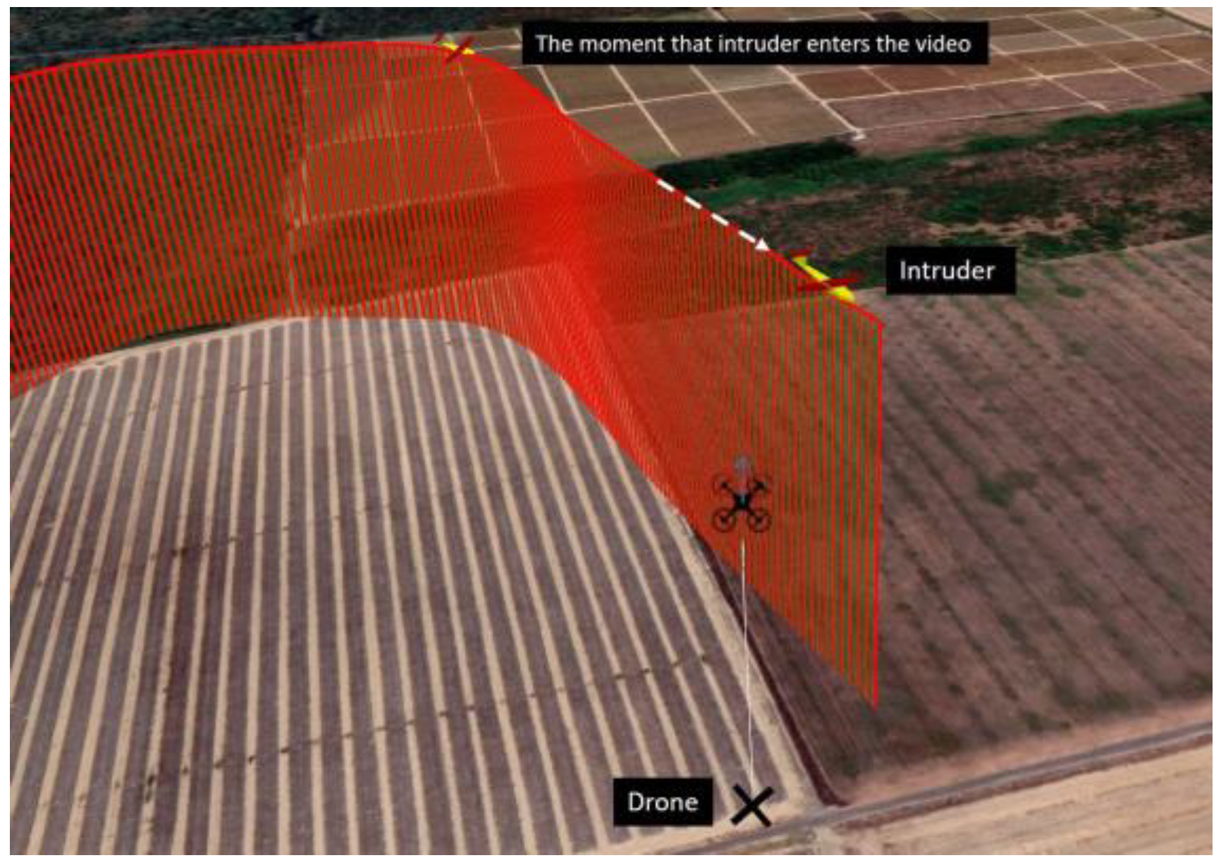
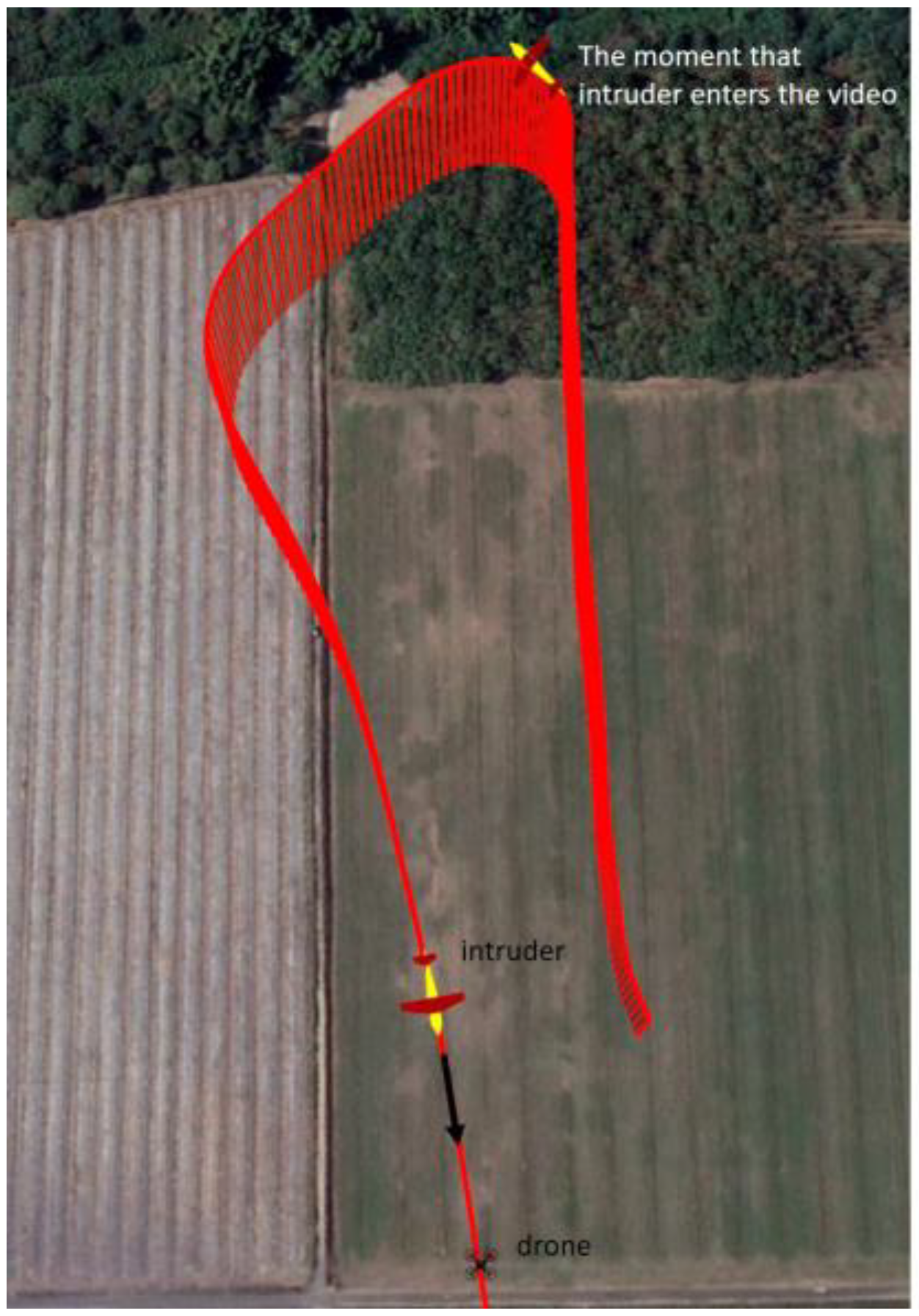
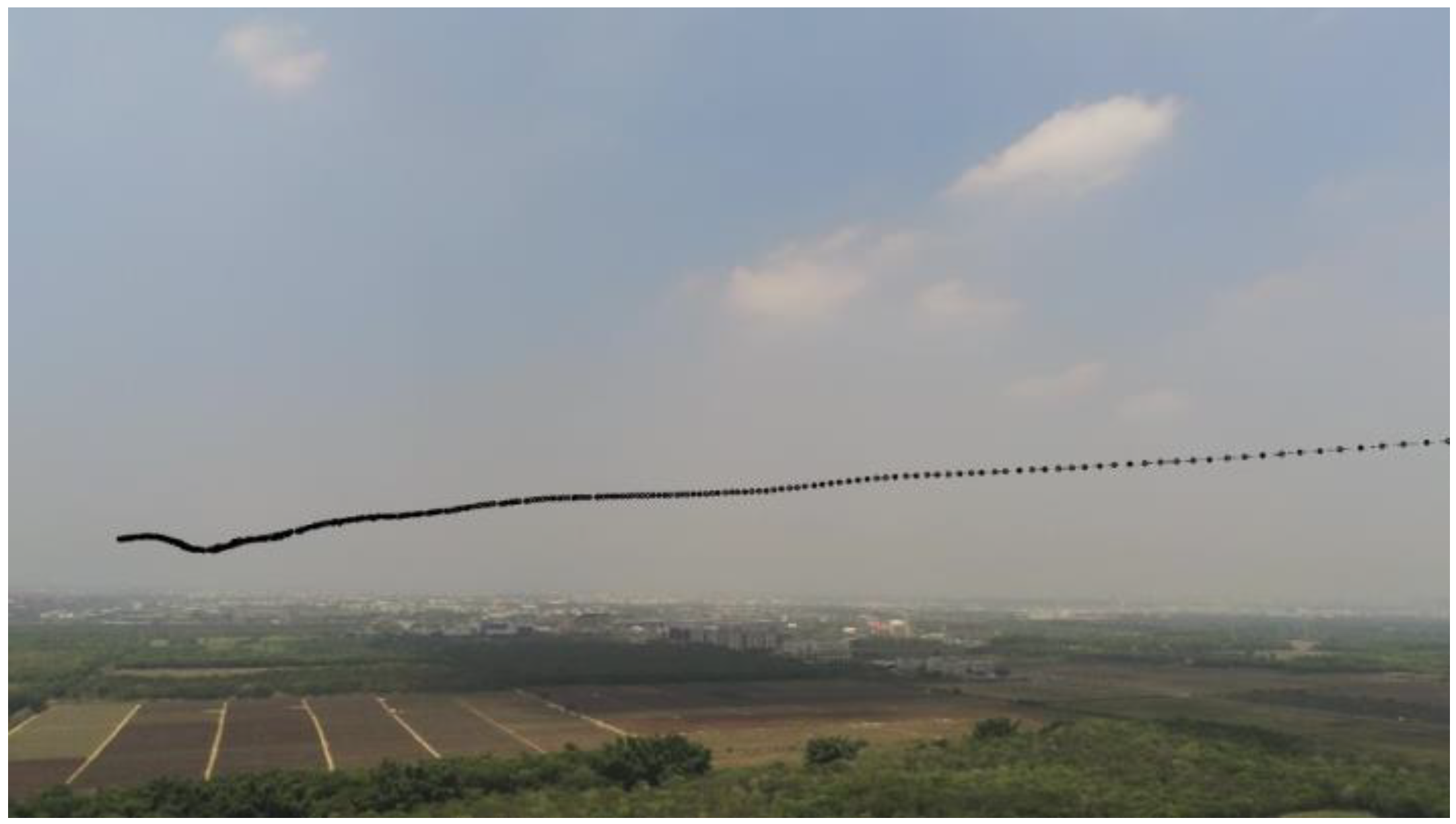
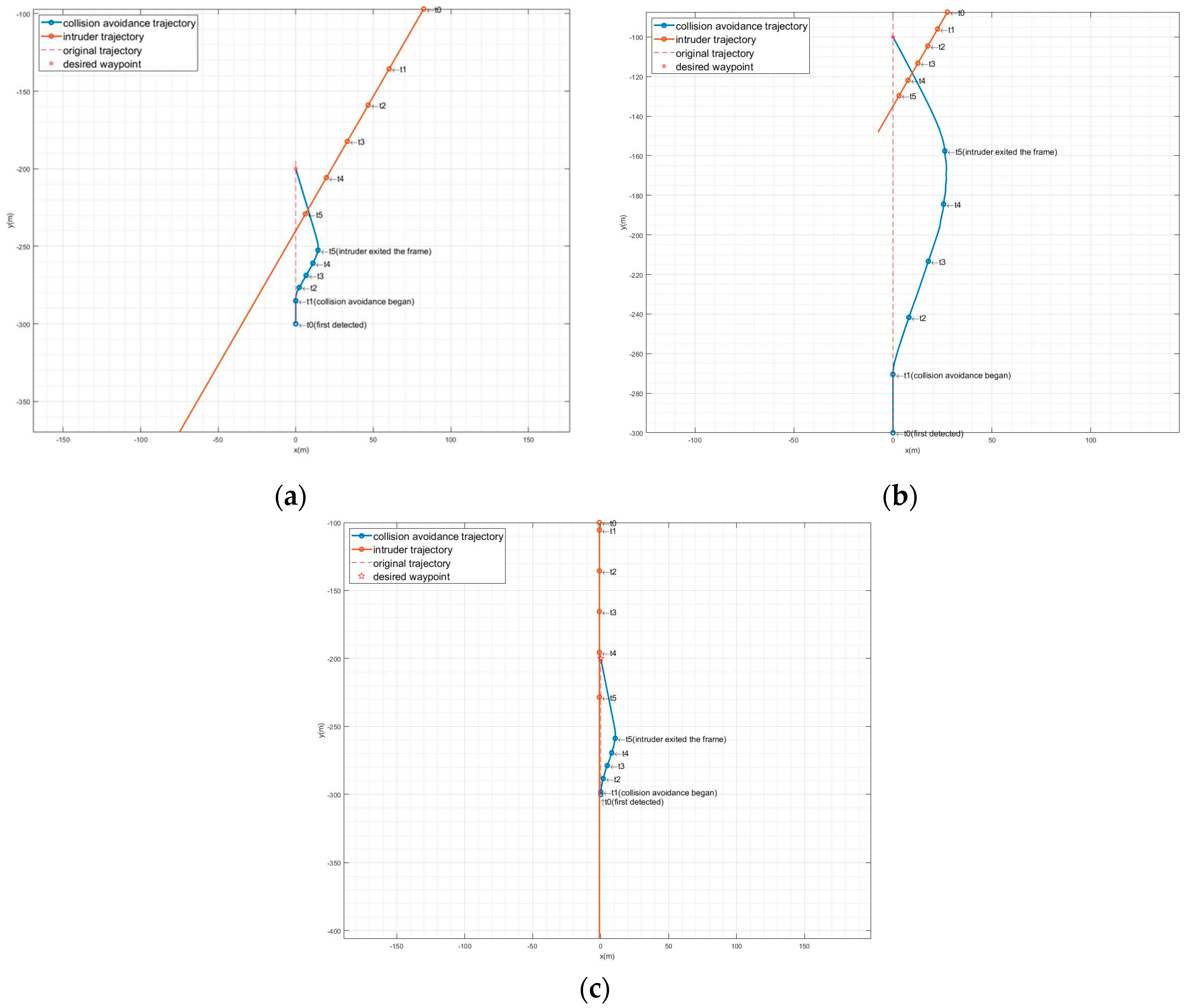
4.1. Real-Flight Experiments

In the real-flight experiments, a Volantex Ranger 2000 V757-8 2000mm, manufactured by Volantex, Zduńska Wola, Poland, was chosen as the intruder, and a Parrot ANAFI drone served as the host aircraft to collect the data. The appearance of the Ranger 2000 is shown in Figure 14, and the specifications of the Ranger 2000 are listed in Table 2. For the convenience of sampling GPS points, the host hovered over a fixed point. Two cases, crossing and head-on, were investigated to test the object detection and area estimation capabilities. Information about the experiment cases is shown in Table 3. In the crossing case, the intruder crosses from left to right. Whereas in the head-on case, the intruder first turns to the camera and flies straight into the camera. Top-view, 3D trajectories of the intruder in the experiments are shown in Figure 15 and Figure 16. The maximum detection range is about 400 m, which meets the DAA requirements for UTM.
In the crossing experiment, the intruder was first detected 350 m away from the camera, and the Mask R-CNN model recognized it successfully as well. The trajectory of the intruder on the 2D image plane, which is detected by the background subtraction method with the help of a Kalman filter to eliminate background noise, is shown in Figure 17. The proposed method can produce a smooth and continuous trajectory. The results of the area estimation of the intruder are shown in Figure 18 and Figure 19 for the crossing and head-on cases, respectively. After the data was smoothed using a Kalman filter, the regression curve was found, which represents the area expansion curve of the intruder.

4.2. Collision Avoidance Simulations

The simulations were conducted to verify the feasibility and performance of the proposed collision avoidance approach, including the detection of an intruder, the estimation of the flight area, the assessment of collision risk, and the avoidance of mid-air collisions in the simulations. Different simulated scenarios, including different sizes and types of intruders and different velocities of intruders and host aircraft, were executed. Two different wingspans in the Sky Surfer fixed-wing UAV model and a fly-wing model were used in the simulations as intruders. The simulations were carried out using Blender 2.8 software. The intruder-approaching simulations were presented in the form of three-dimensional animations rendered by Blender software [38], and the trajectory control of the host was calculated with Python code to determine the camera parameters in the simulations. The sampling rate of collision risk is set to 3 Hz to match the actual computing speed. The camera information is shown in Table 4, and the simulation cases and conditions are shown in Table 5.
The proposed collision risk is composed of three factors: area expansion, position, and bearing. The weightings for the three collision risk factors are determined by a bio-inspired algorithm. For an animal’s vision system, the TTC is the most crucial component of determining whether the intruder is a threat or not. In a single-vision system, the TTC is roughly estimated by the size expansion rate of the intruder. Therefore, the area expansion ratio should be the main factor that affects the collision risk. In addition to the TTC, the position of the intruder also significantly affects the collision risk. As for the bearing angle of the intruder, it has less effect on determining the collision risk since it is mostly used to determine whether the intruder is approaching the center of the image. After trying several sets of distributions of weights, the best distribution that matches the requirements of most scenarios was found to be w a = 0.5 , w p = 0.333 , a n d   w b = 0.167 . The maximum angular velocity of the host aircraft was set to θ ˙ m a x = π / 2 rad/s, and the gain used for the θ ˙ t r calculation was set to k t r = 1.5 .
The results are shown in Table 6. The performance is evaluated based on the detected range, the distance when the collision avoidance began, the minimum TTC, and the minimum separation distance (MSD). The detected range is the distance between the host and the intruder when the intruder is first detected. The distance when collision avoidance began is the distance between the host and the intruder when the collision risk assessment triggered collision avoidance. The minimum TTC is the estimated minimum time to the closest point of approach. The MSD is the minimum separation distance between the host and the intruder. For these four evaluations, the larger these values are, the safer the host flight is and the better the proposed collision avoidance approach.
For the crossing cases, the intruder approached the host aircraft at an angle of 30 degrees from the right. For the head-on cases, the intruder approached the host aircraft straightforwardly. The corresponding video frames of Crossing 1-I are shown in Figure 20, and it shows that as the intruder approaches, the estimated areas increase. Figure 21 shows the corresponding video frames of Head-on I, and the estimated areas are also increasing when the intruder is approaching. The trajectories of the host and intruder in all cases are shown in Figure 22.
As supported by Table 6 and Figure 22, the proposed collision avoidance approach allows the host aircraft to successfully detect and avoid the different types, sizes, and velocities of intruders. Since the collision risk is assessed based on the area expansion rate in this study, the simulated results of different sizes of intruders should be about the same. Therefore, in Crossing 1 and Crossing 2, the minimum TTCs only have 1.69 (s) and 0.66 (s) differences, which means the proposed method is applicable to different sizes of intruders. For the host aircraft with speeds of 5 m/s, the average minimum TTC is 30% less than those with a speed of 15 m/s, and the relative speed in each case is the same (20 m/s). This means that the avoidance efficiency is related to the evasion speed of the host aircraft.
In Figure 22, a few timestamps are shown to indicate the positions of the host and intruder aircraft. t 0 is the time when the intruder is first detected, t 1 is the time when collision avoidance begins, and t_5 is the time when the intruder is out of sight. The total time for which the intruder is in the host’s sight for the different cases in the order shown in Table 6 is 13.3, 13.6, 12.67, 11.6, 12.67, 14.0, and 11.3, respectively. All cases have achieved the goal of this research, which is to detect the intruder 10 s before the collision.

5. Conclusions

In this study, a vision-based mid-air object detection and avoidance approach for small fixed-wing UAVs was developed with the help of deep learning and risk assessment methods. The proposed collision avoidance approach consists of three stages: (1) intruder detection, (2) area estimation, and (3) collision risk assessment and collision avoidance. Firstly, a moving intruder is successfully detected by the background subtraction method without depth information. Secondly, a custom-trained Mask R-CNN model is utilized to recognize the class of the fixed-wing intruder and estimate its area. Thirdly, the collision risk of the intruder is assessed by analyzing its area expansion ratio, coordinates in the image, and relative motion in the image. The background subtraction and area estimation methods were evaluated with real flight videos, and the results successfully achieved our objectives. The maximum detection range of the proposed vision-based detection method is about 400 m, which meets the DAA requirements for UTM. The risk-based collision avoidance method was evaluated by the simulations, and the results show that the host aircraft avoided the intruder by a safe distance and TTC in most of the scenarios. All the cases achieved the goal of this research, which is to detect the intruder 10 s before the collision. Some future works that can improve the proposed approach include optimizing the weighting distribution of the collision risk to improve the efficiency of collision avoidance and extending the custom Mask R-CNN dataset by adding different kinds of UAVs, such as quadcopters and helicopters.

Author Contributions

Conceptualization, Y.-C.L. and T.-Y.L.; methodology, Y.-C.L.; software, T.-Y.L.; validation, Y.-C.L. and T.-Y.L.; formal analysis, Y.-C.L.; investigation, Y.-C.L. and T.-Y.L.; resources, Y.-C.L.; data curation, Y.-C.L. and T.-Y.L.; writing—original draft preparation, T.-Y.L.; writing—review and editing, Y.-C.L. and T.-Y.L.; visualization, T.-Y.L.; supervision, Y.-C.L.; project administration, Y.-C.L.; funding acquisition, Y.-C.L. All authors have read and agreed to the published version of the manuscript.

Funding

This research was funded by the National Science and Technology Council (NSTC), grant number NSTC 112-2622-E-006-002 and NSTC 112-2221-E-006-105-MY3.

Data Availability Statement

The raw data supporting the conclusions of this article will be made available by the authors on request.

Conflicts of Interest

The authors declare no conflicts of interest.

References

  1. Belwafi, K.; Alkadi, R.; Alameri, S.A.; Al Hamadi, H.; Shoufan, A. Unmanned aerial vehicles’ remote identification: A tutorial and survey. IEEE Access 2022, 10, 87577–87601. [Google Scholar] [CrossRef]
  2. Kopardekar, P. Unmanned Aerial System (UAS) Traffic Management (UTM): Enabling Low-Altitude Airspace and Uas Operations; National Aeronautics and Space Administration, Ames Research Center: Mountain View, CA, USA, 2014.
  3. Ferguson, A. Pathfinder Focus Area 2 Phase iii Report. Available online: https://www.faapathfinderreport.com/ (accessed on 18 February 2024).
  4. Redmon, J.; Farhadi, A. Yolov3: An incremental improvement. arXiv 2018, arXiv:1804.02767. [Google Scholar]
  5. Yu, X.; Zhang, Y. Sense and avoid technologies with applications to unmanned aircraft systems: Review and prospects. Prog. Aerosp. Sci. 2015, 74, 152–166. [Google Scholar] [CrossRef]
  6. Lu, L.; Fasano, G.; Carrio, A.; Lei, M.; Bavle, H.; Campoy, P. A comprehensive survey on non-cooperative collision avoidance for micro aerial vehicles: Sensing and obstacle detection. J. Field Robot. 2023, 40, 1697–1720. [Google Scholar] [CrossRef]
  7. Choe, R.; Cichella, V.; Xargay, E.; Hovakimyan, N.; Trujillo, A.C.; Kaminer, I. A Trajectory-Generation Framework for Time-Critical Cooperative Missions. In Proceedings of the AIAA Infotech@ Aerospace (I@ A) Conference, Boston, MA, USA, 19–22 August 2013; p. 4582. [Google Scholar]
  8. Cichella, V.; Kaminer, I.; Walton, C.; Hovakimyan, N. Optimal motion planning for differentially flat systems using bernstein approximation. IEEE Control Syst. Lett. 2017, 2, 181–186. [Google Scholar] [CrossRef]
  9. Subchan, S.; White, B.; Tsourdos, A.; Shanmugavel, M.; Zbikowski, R. Pythagorean hodograph (ph) path planning for tracking airborne contaminant using sensor swarm. In Proceedings of the 2008 IEEE Instrumentation and Measurement Technology Conference, Victoria, BC, Canada, 12–15 May 2008; pp. 501–506. [Google Scholar]
  10. Chandler, P.; Rasmussen, S.; Pachter, M. Uav cooperative path planning. In Proceedings of the AIAA Guidance, Navigation, and Control Conference and Exhibit, Dever, CO, USA, 14–17 August 2000; p. 4370. [Google Scholar]
  11. Zhang, B.; Liu, W.; Mao, Z.; Liu, J.; Shen, L. Cooperative and geometric learning algorithm (cgla) for path planning of uavs with limited information. Automatica 2014, 50, 809–820. [Google Scholar] [CrossRef]
  12. Chen, Y.-B.; Luo, G.-C.; Mei, Y.-S.; Yu, J.-Q.; Su, X.-L. Uav path planning using artificial potential field method updated by optimal control theory. Int. J. Syst. Sci. 2016, 47, 1407–1420. [Google Scholar] [CrossRef]
  13. Carbone, C.; Ciniglio, U.; Corraro, F.; Luongo, S. A novel 3d geometric algorithm for aircraft autonomous collision avoidance. In Proceedings of the 45th IEEE Conference on Decision and Control, San Diego, CA, USA, 13–15 December 2006; pp. 1580–1585. [Google Scholar]
  14. Fasano, G.; Accardo, D.; Moccia, A.; Carbone, C.; Ciniglio, U.; Corraro, F.; Luongo, S. Multi-sensor-based fully autonomous non-cooperative collision avoidance system for unmanned air vehicles. J. Aerosp. Comput. Inf. Commun. 2008, 5, 338–360. [Google Scholar] [CrossRef]
  15. Ren, W.; Beard, R.W. Trajectory tracking for unmanned air vehicles with velocity and heading rate constraints. IEEE Trans. Control Syst. Technol. 2004, 12, 706–716. [Google Scholar] [CrossRef]
  16. Zhang, Y.; Wang, W.; Huang, P.; Jiang, Z. Monocular vision-based sense and avoid of uav using nonlinear model predictive control. Robotica 2019, 37, 1582–1594. [Google Scholar] [CrossRef]
  17. Viquerat, A.; Blackhall, L.; Reid, A.; Sukkarieh, S.; Brooker, G. Reactive collision avoidance for unmanned aerial vehicles using doppler radar. In Field and Service Robotics; Springer: Berlin/Heidelberg, Germany, 2008; pp. 245–254. [Google Scholar]
  18. Lai, Y.-C.; Huang, Z.-Y. Detection of a moving uav based on deep learning-based distance estimation. Remote Sens. 2020, 12, 3035. [Google Scholar] [CrossRef]
  19. Saqib, M.; Khan, S.D.; Sharma, N.; Blumenstein, M. A study on detecting drones using deep convolutional neural networks. In Proceedings of the 2017 14th IEEE International Conference on Advanced Video and Signal Based Surveillance (AVSS), Lecce, Italy, 29 August–1 September 2017; pp. 1–5. [Google Scholar]
  20. Schumann, A.; Sommer, L.; Klatte, J.; Schuchert, T.; Beyerer, J. Deep cross-domain flying object classification for robust uav detection. In Proceedings of the 2017 14th IEEE International Conference on Advanced Video and Signal Based Surveillance (AVSS), Lecce, Italy, 29 August–1 September 2017; pp. 1–6. [Google Scholar]
  21. Opromolla, R.; Fasano, G.; Accardo, D. A vision-based approach to uav detection and tracking in cooperative applications. Sensors 2018, 18, 3391. [Google Scholar] [CrossRef]
  22. Jin, R.; Jiang, J.; Qi, Y.; Lin, D.; Song, T. Drone detection and pose estimation using relational graph networks. Sensors 2019, 19, 1479. [Google Scholar] [CrossRef]
  23. Wu, M.; Xie, W.; Shi, X.; Shao, P.; Shi, Z. Real-time drone detection using deep learning approach. In Proceedings of the International Conference on Machine Learning and Intelligent Communications, Hangzhou, China, 6–8 July 2018; Springer: Berlin/Heidelberg, Germany, 2018; pp. 22–32. [Google Scholar]
  24. Redmon, J.; Divvala, S.; Girshick, R.; Farhadi, A. You only look once: Unified, real-time object detection. In Proceedings of the IEEE Conference on Computer Vision and Pattern Recognition, Las Vegas, NV, USA, 26 June–1 July 2016; pp. 779–788. [Google Scholar]
  25. Diwan, T.; Anirudh, G.; Tembhurne, J.V. Object detection using yolo: Challenges, architectural successors, datasets and applications. Multimed. Tools Appl. 2023, 82, 9243–9275. [Google Scholar] [CrossRef]
  26. Yang, Y.; Gao, X.; Wang, Y.; Song, S. Vamyolox: An accurate and efficient object detection algorithm based on visual attention mechanism for uav optical sensors. IEEE Sens. J. 2022, 23, 11139–11155. [Google Scholar] [CrossRef]
  27. Xing, J.; Liu, Y.; Zhang, G.-Z. Improved yolov5-based uav pavement crack detection. IEEE Sens. J. 2023, 23, 15901–15909. [Google Scholar] [CrossRef]
  28. Vera-Yanez, D.; Pereira, A.; Rodrigues, N.; Molina, J.P.; García, A.S.; Fernández-Caballero, A. Vision-based flying obstacle detection for avoiding midair collisions: A systematic review. J. Imaging 2023, 9, 194. [Google Scholar] [CrossRef]
  29. Li, J.; Ye, D.H.; Chung, T.; Kolsch, M.; Wachs, J.; Bouman, C. Multi-target detection and tracking from a single camera in unmanned aerial vehicles (uavs). In Proceedings of the 2016 IEEE/RSJ International Conference on Intelligent Robots and Systems (IROS), Daejeon, Republic of Korea, 9–14 October 2016; pp. 4992–4997. [Google Scholar]
  30. Woo, J.; Kim, N. Vision-based target motion analysis and collision avoidance of unmanned surface vehicles. Proc. Inst. Mech. Eng. Part M J. Eng. Marit. Environ. 2016, 230, 566–578. [Google Scholar] [CrossRef]
  31. Lyu, Y.; Pan, Q.; Zhao, C.; Zhang, Y.; Hu, J. Vision-based uav collision avoidance with 2d dynamic safety envelope. IEEE Aerosp. Electron. Syst. Mag. 2016, 31, 16–26. [Google Scholar] [CrossRef]
  32. Marinho, T. Bio-Inspired Vision-Based Evasion Control: Collision Avoidance without Distance Measurement; University of Illinois at Urbana-Champaign: Champaign, IL, USA, 2019. [Google Scholar]
  33. Cichella, V.; Marinho, T.; Stipanović, D.; Hovakimyan, N.; Kaminer, I.; Trujillo, A. Collision avoidance based on line-of-sight angle. J. Intell. Robot. Syst. 2018, 89, 139–153. [Google Scholar] [CrossRef]
  34. He, K.; Gkioxari, G.; Dollár, P.; Girshick, R. Mask r-cnn. In Proceedings of the IEEE International Conference on Computer Vision, Venice, Italy, 2–29 October 2017; pp. 2961–2969. [Google Scholar]
  35. Su, H.; Wei, S.; Yan, M.; Wang, C.; Shi, J.; Zhang, X. Object detection and instance segmentation in remote sensing imagery based on precise mask r-cnn. In Proceedings of the IGARSS 2019-2019 IEEE International Geoscience and Remote Sensing Symposium, Yokohama, Japan, 28 July–2 August 2019; pp. 1454–1457. [Google Scholar]
  36. Lin, T.-Y.; Maire, M.; Belongie, S.; Hays, J.; Perona, P.; Ramanan, D.; Dollár, P.; Zitnick, C.L. Microsoft coco: Common objects in context. In European Conference on Computer Vision; Springer: Berlin/Heidelberg, Germany, 2014; pp. 740–755. [Google Scholar]
  37. Deng, J.; Dong, W.; Socher, R.; Li, L.-J.; Li, K.; Fei-Fei, L. Imagenet: A large-scale hierarchical image database. In Proceedings of the 2009 IEEE Conference on Computer Vision and Pattern Recognition, Miami, FL, USA, 20–25 June 2009; pp. 248–255. [Google Scholar]
  38. Alecu, F. Blender institute–the institute for open 3d projects. Open Source Sci. J. 2010, 2, 36–45. [Google Scholar]
Figure 1. The flow chart of the UAV sensing system.
Remotesensing 16 00756 g001
Figure 2. The process of long-distance object detection.
Remotesensing 16 00756 g002
Figure 3. The architecture of the Mask R-CNN model. (Adapted from [34,35]).
Remotesensing 16 00756 g003
Figure 4. Detection result of custom Mask R-CNN model in a synthetic image.
Remotesensing 16 00756 g004
Figure 5. Detection result of custom Mask R-CNN model in a real-flight video.
Remotesensing 16 00756 g005
Figure 6. The scenario in the synthetic video for evaluation.
Remotesensing 16 00756 g006
Figure 7. Area of the UAV in the synthetic video for evaluation.
Remotesensing 16 00756 g007
Figure 8. Area of the intruder under different approaching speeds in the synthetic video.
Remotesensing 16 00756 g008
Figure 9. Area difference rate under different distance intervals in the synthetic video (approaching speed: 15 m/s).
Remotesensing 16 00756 g009
Figure 10. An illustration of the bearing factor and position factor.
Remotesensing 16 00756 g010
Figure 11. Situations with potential threat of collision and avoidance rules based on VFRs.
Remotesensing 16 00756 g011
Figure 12. The formation of a separation bubble.
Remotesensing 16 00756 g012
Figure 13. An illustration of the path following the controller.
Remotesensing 16 00756 g013
Figure 14. The appearance of Volantex Ranger 2000 V757-8 2000mm.
Remotesensing 16 00756 g014
Figure 15. The 3D trajectory of the intruder in the crossing experiment.
Remotesensing 16 00756 g015
Figure 16. The 3D trajectory of the intruder in the head-on experiment.
Remotesensing 16 00756 g016
Figure 17. The trajectory of the intruder in the image smoothed by Kalman filtering in the crossing experiment.
Remotesensing 16 00756 g017
Figure 18. The area of the intruder in the crossing experiment.
Remotesensing 16 00756 g018
Figure 19. The area of the intruder in the head-on experiment.
Remotesensing 16 00756 g019
Figure 20. The corresponding video frames of Crossing 1-I.
Remotesensing 16 00756 g020
Figure 21. The corresponding video frames of Head-on I.
Remotesensing 16 00756 g021
Figure 22. The trajectories of the intruder and the host aircraft. (a) Crossing 1-I. (b) Crossing 2-I. (c) Head-on I.
Remotesensing 16 00756 g022
Table 1. The attitude specification of the UAVs and image information.
Image InformationValue
Image Resolution1920 × 1080
Focal Length35 mm
AttitudeRange (deg)
Roll−15~15
Pitch−15~15
Yaw−75~75
Table 2. The specifications of Volantex Ranger 2000 V757-8 2000mm.
SpecificationValue
Wingspan2.0 m
Overall Length1.1 m
Height0.25 m
Average Speed20 m/s
Table 3. The information about the experiments.
CaseCrossingHead-On
Video Information
Resolution3840 × 21603420 × 1924
Focal Length35 mm35 mm
FOV69 degrees69 degrees
Frames Per Second3030
WeatherOvercastCloudy
Intruder’s Information
Average Speed20 m/s20 m/s
Altitude100 m50 m
Host’s Information
Altitude90 m45 m
Table 4. Video information in the simulation.
Video InformationValue
Resolution3840 × 2160
Focal Length35 mm
FOV54 degrees
Video Length300 frames
Frames Per Second30
Table 5. Information on collision avoidance cases.
CaseType of the Intruder (Wingspan)Speed of UAVs
VintVhost
Crossing 1IFixed-wing (2.0 m)15 m/s5 m/s
IIFixed-wing (1.4 m)
Crossing 2IFixed-wing (2.0 m)5 m/s15 m/s
IIFixed-wing (1.4 m)
Crossing 3Flywing (3.5 m)15 m/s15 m/s
Head-onIFlywing (3.5 m)15 m/s5 m/s
II5 m/s15 m/s
Table 6. The results of each simulated case.
CaseDistance (m)Min TTC (s)MSD (m)
Detected RangeCollision Avoidance Began
Crossing 1I292.3233.810.1621.52
II292.3285.911.8525.57
Crossing 2I292.4292.414.5442.95
II292.4279.413.8838.54
Crossing 3434.6434.613.9356.61
Head-onI3003005.0115.90
II3003006.9731.14
Disclaimer/Publisher’s Note: The statements, opinions and data contained in all publications are solely those of the individual author(s) and contributor(s) and not of MDPI and/or the editor(s). MDPI and/or the editor(s) disclaim responsibility for any injury to people or property resulting from any ideas, methods, instructions or products referred to in the content.

