Abstract
Ocean salinity is a pivotal aspect of the ocean dynamic environment. Spaceborne L-band radiometers, like SMOS, Aquarius, and SMAP, offer a comprehensive approach to mapping out large-scale ocean salinity patterns. As China prepares for the launch of the Chinese Ocean Salinity and Soil Moisture Mission (COSM), it is essential to delve into the intricacies of radio frequency interference (RFI) detection, localization, and mitigation. The L-band, in particular, is highly susceptible to RFI. COSM will carry not one but two advanced instruments: a 2-D L-band aperture synthesis microwave radiometer (LASMR) and a 1-D L-C-K band microwave imager combined active and passive (MICAP). This article delves into the current state of RFI research, particularly in recent years, and introduces a fusion method that integrates MICAP and LASMR for more accurate RFI detection, localization, and mitigation. This fusion method relies on an algorithm that constructs localization and intensity objective functions based on the principle of least squares. By optimizing these functions, we can pinpoint the precise location and intensity of RFI. The resulting minimum mitigation residual offers a blueprint for achieving optimal RFI detection, localization, and mitigation. The experimental results, achieved in a controlled anechoic chamber, confirm that this fusion method—when weighted by variance—boosts detection accuracy, refines localization precision, and minimizes residual mitigation errors compared with standalone MICAP or LASMR techniques.
1. Introduction
Sea surface salinity (SSS), along with other ocean dynamic environment elements such as sea surface height and temperature, are crucial elements of oceanographic research [1,2,3]. These elements play a pivotal role in the balance of ocean energy and global climate change [1,4,5]. Therefore, ocean salinity observation has always been a significant aspect of ocean remote sensing. The L-band spaceborne radiometer offers a means to measure large-scale ocean salinity patterns using satellites such as SMOS, Aquarius, and SMAP. As China gears up for the launch of its own Chinese Ocean Salinity and Soil Moisture Mission (COSM), accurate detection, localization, and mitigation of radio frequency interference (RFI) become paramount. The L-band, in particular, is highly prone to RFI interference. The acquisition of high-quality ocean salinity products relies on the accurate reception of sea surface L-band radiation by microwave radiometers. However, with increasing human activities and the rapid development of wireless communication, RFI has become a significant challenge. Post-launch analysis of SMOS data revealed significant RFI worldwide [4,6,7,8,9]. Aquarius and SMAP, operating in the same frequency band, face similar challenges [10,11]. Therefore, effective RFI detection, localization, and mitigation are essential for accurate ocean salinity data preprocessing and inversion.
To mitigate the impact of RFI and enhance the accuracy of ocean salinity inversions, COSM is equipped with two payloads: the 2-D L-band aperture synthesis microwave radiometer (LASMR) and the 1-D L-C-K band microwave imager combined active and passive (MICAP). These payloads utilize synthetic aperture interferometric radiometers [12,13,14]. This article delves into the methods of RFI detection, localization, and mitigation using a single radiometer payload [15]. Building upon this foundation, this article introduces a fusion method that combines MICAP and LASMR for RFI detection, localization, and mitigation. This approach aims to enhance the detection and localization accuracy of RFI sources while minimizing mitigation residual.
The remaining sections of the article are listed as follows. Section 2 introduces the work related to the RFI detection, localization, and mitigation of the single payload. Section 3 provides the foundation used in this study. Section 4 provides the experiment used in this study. Section 5 describes the methodology used for the fusion method. Section 6 is devoted to the presentation of the obtained results and to comparison and verification. Finally, Section 7 presents the main conclusions of the study.
2. Related Work of the RFI Detection, Localization, and Mitigation of Single Payload
For the RFI detection, localization, and mitigation of the single payload of SAIR (synthesis aperture interferometer radiometer), much research has been carried out based on SMOS (a two-dimensional on-board SAIR), and a variety of feasible methods have been proposed (which can also be extended to the one-dimensional single-payload synthetic aperture radiometer system).
2.1. RFI Detection and Localization
After the successful launch of the SMOS satellite, researchers from the official SMOS team developed an RFI geolocation method [16,17]. This method uses SMOS L1C data, which consists of the brightness temperature measurement after geolocation. First, initial data filtering is performed to select data from the ground (as most RFI sources are located on land) and from regions close to the nadir point in the snapshot (as they have higher spatial resolution). Second, grid points with unnatural horizontal brightness temperatures (generally greater than 350 K) are searched for in the snapshot to locate RFI sources. At this point, it is necessary to distinguish between regions with high brightness temperatures due to RFI sources and those affected by side lobes of other RFI sources. Experience has shown that the minimum size of a region with a high brightness temperature due to RFI sources is determined by the spatial resolution of the instrument, while regions affected by side lobes of other RFI sources are much smaller. Therefore, using this minimum size can filter out regions with high brightness temperatures due to the side lobes of other RFI sources. The remaining grid points are scanned and aggregations indicating the presence of RFI sources are searched for. Aggregations are interpolated using three-point interpolation on a more sparse grid, and then the ground coordinates of the interpolated peak are inverted. Finally, this method is run on each snapshot in multiple L1C data products, and the positions of all detections of the same RFI source are statistically averaged to improve positioning accuracy. The results show that in most cases, the positioning accuracy of this method is less than 4 km. Thanks to this method, more than 150 RFI sources have been successfully shut down globally.
Castro et al. proposed an improved RFI detection and localization method [18]. This method uses SMOS L1A data, i.e., the calibrated visibility. Considering the impact of aliasing, this method only locates RFI sources that are in the aliasing-free field of view (AF-FOV). First, the visibility of each snapshot is inverted to generate a brightness temperature image, where each pixel with a brightness temperature exceeding the detection threshold is considered to be the location of the RFI source. Its coordinates are projected from the antenna plane to the Earth’s surface using the geolocation program of the L1-level prototype processor (L1PP), and the precise latitude and longitude coordinates of the RFI source are extracted. Then, these coordinates are filled into a rectangular grid with a resolution of [0.25 × 0.25]°, and statistical analysis is performed. Finally, using this grid as input, an RFI source list is generated. This method uses L1A data, reducing the requirements for data processing. At the same time, it relies on statistical analysis to reduce the false alarm rate. Due to the impact of the SMOS swath width, the number of RFI sources detected in the aliasing-free field is limited, which can be improved by using multi-orbit data or extending the working area (such as by performing detection outside of the AF-FOV).
Yan Soldo et al. proposed an RFI geolocation method using SMOS L1B data [19], which is the Fourier component of reconstructed brightness temperature. First, the entire hexagon field of view region is inverted for each snapshot to generate a brightness temperature image. Then, in this brightness temperature image, grid points with high brightness temperatures and high brightness temperature gradients (the brightness temperature gradient refers to the difference in brightness temperature between adjacent grid points) are considered as RFI sources. For these two parameters, the method adopts adaptive thresholds, which are set as follows: , , where is the peak brightness temperature in the hexagon field of view. Starting from the center of each point cluster, the Nelder–Mead optimization method is used to identify the local peak of the brightness temperature. This optimization method iteratively evaluates the Fourier component of reconstructed brightness temperature near the center of the point cluster to find the location of the brightness temperature peak. The results provide the coordinates of detected RFI sources. The researchers conducted a test experiment on a subset of stations located along the remote early warning (DEW) line in northern Canada. The results indicate that the positioning performance of this method is related to seasonal variations and the positions of RFI sources within the field of view. There is a positioning bias between ascending and descending channels. Since this method does not perform RFI suppression, it can only detect RFI sources with similar intensities for each snapshot. When there are two RFI sources with significantly different intensities, the stronger RFI source will mask the weaker one, making it impossible to display the latter independently in the brightness temperature image. This method considers the entire hexagon field of view region to minimize false alarms.
To improve angular resolution and reduce sidelobes, Hyuk Park et al. proposed a super-resolution localization method based on the estimation of the direction of arrival (DOA). This method is based on the multiple signal classification (MUSIC) algorithm, a subspace decomposition method that utilizes the orthogonality between the noise subspace and the signal subspace in array signal processing. Since the MUSIC pseudo-spectrum produces peaks in the direction of the signal sources, and the MUSIC method treats RFI sources as signal sources while other signals are treated as background noise, it can utilize the spectral peak locations to localize RFI sources. The experimental results demonstrated that this method has high spatial resolution and can separate multiple close-range RFI sources within a resolution cell, which is not possible with previous methods based on abnormal peak detection in brightness temperature images. In the localization performance of the MUSIC method [20], the Capon algorithm and the traditional DFT algorithm are compared, demonstrating the superiority of the MUSIC method in terms of localization accuracy and spatial resolution. To improve the localization accuracy, Hyuk Park et al. improved the MUSIC method by incorporating rank estimation of the covariance matrix and multi-snapshot processing [21], further enhancing the localization accuracy of this method.
Next, a series of improvements was made to the MUSIC algorithm, such as the augmented covariance matrix method [22,23], a localization method based on compressed sensing [24,25].
2.2. RFI Mitigation
The SMOS official team’s researchers developed an RFI suppression method based on the solar impact elimination algorithm [26]. After geolocation, the intensity of the RFI source is estimated based on the original brightness temperature, average brightness temperature of the scene, and the instrument’s point source response. It calculates the visibility function of the RFI source and subtracts it from the measured visibility. This method performs well in cases of low RFI source intensity and can suppress RFI sources located within the non-aliased field AF-FOV. However, it cannot handle strong RFI sources located in aliased areas. The suppression performance of this method relies heavily on accurate estimates of the RFI source’s position and intensity. When the RFI source is located in a non-uniform scene, inaccurate intensity estimation can introduce significant errors. Additionally, changes in the intensity of the same RFI source can also affect the suppression performance.
Yan Soldo et al. proposed an improved RFI suppression method [27,28]. First, they observed the brightness temperature distribution and gradient in the differential brightness temperature scene and defined clusters around local maxima. Since strong RFI sources may mask weaker sources, after RFI correction, clusters must be iteratively defined with gradually decreasing thresholds. Once clusters are identified, the method simulates RFI sources distributively by simulating multiple RFI sources within a cluster to obtain a brightness temperature distribution that closely matches the distribution pattern in the measured data. This method is particularly effective for weak RFI sources, but performs less well than expected for particularly strong sources and may even introduce additional errors.
A. Camps et al. proposed an RFI suppression method based on the CLEAN algorithm [26]. This method is very effective at suppressing isolated RFI point sources, but it has two issues. First, it cannot handle RFI extended sources because its premise assumes that RFI sources consist of a collection of isolated point sources. Second, this method can be viewed as a parameter estimation problem, so accurate estimation of parameters such as the precise location and intensity of RFI sources is crucial for this method. However, in non-uniform scenes, interactions between multiple RFI sources that are close together within a resolution element can lead to parameter estimation errors and subsequently degrade the performance and accuracy. To address the first issue, Fei. Hu et al. proposed an improved method for RFI extended sources [29]. In essence, the ultimate goal of RFI suppression is to minimize artifacts caused by RFI source side lobes. This method adds an array factor to the brightness temperature image to construct a beam centered on the RFI source location that approaches a Gaussian beam as closely as possible. The low side lobe characteristic of the Gaussian beam reduces artifacts caused by the RFI source’s side lobes. This method uses an iterative parameter estimation process similar to that of traditional CLEAN methods. Since this method is based on SAIR’s array factor, it can only handle RFI sources with constant intensity. Compared with traditional CLEAN methods, this method performs better at suppressing RFI extended sources, but less well at suppressing RFI point sources. To address the second issue, Xiaohui Peng et al. proposed an improved method [30] for handling interactions between two or more closely spaced RFI sources. The objective of this method is to minimize parameter estimation errors caused by interactions between adjacent RFI sources. The principle behind this method is that most of the side lobes of RFI sources that cause parameter estimation errors have already been reduced in cleaned images. Therefore, if a previously detected RFI source is added back into the cleaned image, a better estimate of its location and intensity can be obtained. Experimental results based on SMOS data demonstrate that this method improves the suppression of interactions between two isolated RFI point sources.
Next, a series of improvements was made to the CLEAN algorithm, such as the array factor synthesis method [31,32,33], the RFI suppression method without prior information of location and energy [15,34], and the adaptive fast iterative CLEAN algorithm [35].
2.3. Summary
It should be pointed out that, despite the large number of RFI processing algorithms proposed, due to the inherent resolution and sensitivity limitations of SAIR, the RFI localization results still have errors at the kilometer level, and the suppression results still have residuals of several to tens of Kelvin. Therefore, there is still much room for improvement in performance. This article aims to further improve the performance of single-load RFI localization and suppression algorithms by combining the algorithms to fully tap into the potential of dual-load technology.
3. Foundation
In this section, the system configuration of a COSM system composed of two payloads will be introduced.
3.1. Satellite and Payload Description
The design sketch of a COSM with two payloads is presented in Figure 1. The two payloads are 2-D L-band aperture synthesis microwave radiometer (LASMR) and 1-D L-C-K band microwave imager combined active and passive (MICAP).
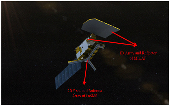
Figure 1.
Chinese ocean salinity and soil moisture mission (COSM).
The LASMR payload is an L-band (center frequency is 1.4 GHz), fully polarized 2-D aperture synthesis microwave radiometer, which features a moderate radiometric resolution, high spatial resolution, and multiangle characteristics by which to observe SSS [36]. These characteristics are benefits of the 2-D Y-shaped array structure; as shown in Figure 2, LASMR is similar to SMOS’ MIRAS (microwave interferometric radiometer with two-dimensional aperture synthesis) in terms of array type (they are both Y-shaped arrays), but differs in terms of array orientation and the number of antenna elements. As can be seen from Figure 2, the Y-shaped antenna array contains 56 feed elements which are equally distributed across three arms. The three arms are labeled Arm-a, -b, and -c, with an angular separation of 120°. Arm-a has 17 feed elements, and the other two arms have 18 feed elements; the remaining 3 elements are placed in the center and are treated as noise injection units. The minimum spacing of each antenna element is 0.82 wavelength of the L-band (0.82λL) [12].
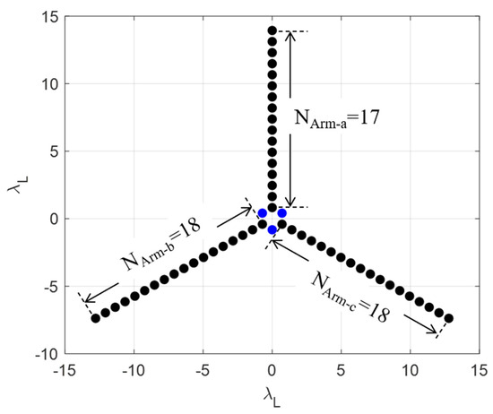
Figure 2.
LASMR’s Y-shaped antenna array with the spacing of antenna elements normalized to the wavelength of the L-band (λL), and the element numbers in each arm are labeled NArm-a, NArm-b, and NArm-c [12,13].
MICAP is a suite of active and passive device packages which includes three interferometric radiometers (L-band: 1.4 GHz, C-band: 6.9 GHz, and K-band: 18.7 GHz) and an L-band digital beamforming scatterometer sharing one parabolic cylinder reflector [37]. The antenna array structures are shown in Figure 3. The L-, C-, and K-band antenna feed elements are arranged in a line, and the total length of the L-band array is about 3 m. The scatterometer elements (green rectangles in Figure 3) are arranged below the radiometer arrays. For the three radiometer arrays, the L-band array contains 10 elements (black rectangles in Figure 3), and both the C- and K-band arrays have 12 elements (blue and red rectangles in Figure 3). The minimum antenna spacings are all set to 0.61 wavelength of the corresponding wavelength (0.61 λL, 0.61 λC, and 0.61 λK), which ensures the same swath widths on the ground. As the interferometric radiometers with 1-D antenna arrays share a reflector, MICAP only possesses its aperture synthesis feature in one direction (along the x-axis in Figure 3, cross-track in-orbit), and another direction (along track) has a real aperture feature decided by the reflector [12].
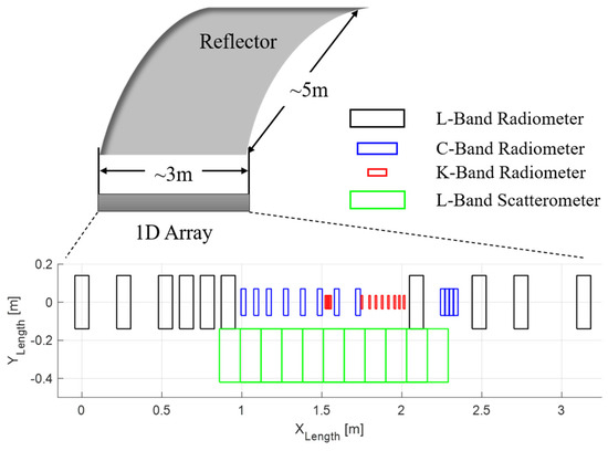
Figure 3.
MICAP’s L-, C-, and K-band antenna arrays arranged in a line, and the L-band scatterometer, sharing a reflector [12,13].
Table 1 lists some of the payload’s system parameters related to LASMR and MICAP, which are used in the interferometric radiometer experiment and reconstruction of the brightness temperature image.

Table 1.
Part of payload’s main system parameters related to LASMR and MICAP [12].
The LASMR payload, which was manufactured by the China Academy of Space Technology, Xi’an in China, is an L-band, fully polarized 2-D aperture synthesis microwave radiometer. The MICAP payload, which was manufactured by National Space Science Center/Center for Space Science and Applied Research, Chinese Academy of Sciences in China, contains an L-band, fully polarized 1-D aperture synthesis microwave radiometer. They have a common overlapping field of view (FOV), as shown in Figure 4. Therefore, for this article, we chose the common overlapping field of view (FOV) L-band for RFI detection, localization, and mitigation to fuse.
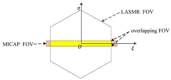
Figure 4.
Field of view.
3.2. Theory of Interferometric Radiometer
The output of an interferometric radiometer instrument is a series of visibility function samples, which are cross-correlations of the signals collected by two antennas [12,13,14]. In the spatial-frequency domain, the visibility Vi,j between the antenna pairs (i, j), where i ≠ j, is a complex function, as expressed in (1), which is related to TB in the antenna coordinate through Fourier transform [12,14,16].
where the baseline (u, v) is the distance between the ith and jth elements normalized to the wavelength. TB (ξ, η) is the BT of the observed scene; (ξ; η) = (sinθcosφ; sinθ sinφ) are the direction cosines; F represents the antenna pattern for each array element; and Fi (ξ, η) and F∗j (ξ, η) are the conjugate pairs for the i th and j th elements. Ω represents the solid angle of each element. The fringe-washing function accounts for the spatial decorrelation effect, and is approximated to ≈ , where B is the bandwidth and f0 is the center frequency. The baselines for LASMR are 2-D vectors (u, v); regarding the 1-D interferometric radiometer of MICAP, the baselines are 1-D (v = 0), and (1) can be rewritten by assuming η = 0. As can be seen from Figure 4, MICAP FOV is a brown rectangular area, LASMR FOV is a white hexagonal area, and the overlapping FOV is a yellow rectangular area.
As Figure 4 shows, the LASMR FOV was larger than that of MICAP. We selected the RFI sources that fell within the overlapping FOVs for fusion processing. If the RFI source was outside the overlapping FOVs, we utilized LASMR to process them individually.
4. Experiment Settings
In this section, the experimental settings of system configuration, input data, and verification data are introduced, respectively.
4.1. System Configuration
An experimental study was conducted in the anechoic chamber. A top view of the anechoic chamber experiment is shown in Figure 5. The anechoic chamber experiment mainly included COSM, RFI source, and other ground equipment. The COSM FOV was upward. The RFI source was located 10 m away from COSM and emitted RFI signals from top to bottom. Other ground equipment mainly generated RFI sources and input them into RFI antennas, and received and processed MICAP and LASMR data.
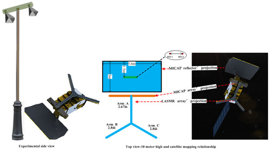
Figure 5.
Side view and top view of anechoic chamber experiment.
4.2. Input Data
In this scene, background environmental data came from the real non-RFI scene of the anechoic chamber. The true scene dataset was obtained by adding various RFI source distributions to the background environmental data. The true RFI distance between two RFI sources was constant. The true RFI localizations were RFI_ξ_position = [ξ1, ξ2] = [0.1, −0.15], RFI_η_position = [η1, η2] = [0, 0]. The frequency point of RFI-1 was 1410 MHz. The frequency point of RFI-2 was 1420 MHz. The RFI sources were as follows: A: weak source, 450 K; B: moderate source, 1200 K; C: strong source, and 5500 K; D: extremely strong source, 10,000 K. The intensity distribution of the RFI sources is shown in Table 2.

Table 2.
Anechoic chamber experiment settings.
(1) The background environmental data and field of view of MICAP were obtained through the anechoic chamber experiment of COSM.
(2) The background environmental data and field of view of LASMR were obtained through the anechoic chamber experiment of COSM.
(3) Four categories of RFI sources (weak, moderate, strong, and extremely strong) in different combinations were added to the background environment using 1-D (MICAP), 2-D (LASMR), and data fusion of 1-D and 2-D. All kinds of detection, localization, and mitigation methods were performed in the experiment environment.
4.3. Verification Data
The RFI true data included localization and intensity, which were used to assess the RFI localization accuracy and the intensity determination accuracy. The data obtained from the anechoic chamber without RFI were used to assess the mitigated residual error.
5. Method
In this section, the overview of the method, the least squares criterion used, and performance evaluation indicators are introduced, respectively, and based on this, the steps of the fusion method and verification process are summarized.
5.1. Fusion Method Overview
This article proposes a fusion method of RFI detection, localization, and mitigation by combining MICAP and LASMR. Figure 4 shows that the fields of view of MICAP and LASMR are different; RFI may be located in different fields of view. This article focuses on the overlapping FOV of MICAP and LASMR.
Thus, the fusion method takes the following aspects into consideration.
1. Considering that the along-orbit direction (η dimension) of MICAP is a real aperture system, the across-orbit direction (ξ dimension) is a synthetic aperture system, which has a higher spatial resolution compared with a real aperture system [12]. LASMR adopts a synthetic aperture system in both the along- and across-orbit directions, with high spatial resolution. The fusion method of RFI detection, localization, and mitigation by combining MICAP and LASMR should construct different objective functions in the along-orbit and across-orbit directions.
2. Considering that the FOV of MICAP and the FOV of LASMR are different, the visibility and the brightness temperature are different; MICAP and LASMR should singly evaluate the mitigating residual performance.
Section 5.1 analyzes how to construct the fusion object function based on the weighted lease square criterion in the along-orbit direction and the across-orbit direction. Section 5.2 proposes the fusion performance evaluation method. Section 5.3 proposes steps to implement the fusion method and verification process.
5.2. Fusion Method Based on Weighted Least Square Principle
The fusion method was constructed based on the weighted least square principle in statistics. Its basic idea is to use the error between measured data and true data as a constraint condition, and to solve the optimal estimation value that minimizes the error by constructing a weighted least square problem, thereby obtaining a more accurate estimation of the true value.
In this process, observation data of good data quality are given higher weight, while data of poor quality are given lower weights to ensure the accuracy and reliability of the fusion results. In the experiment, the weight factor is represented by the measurement data variance. If the variance is small, it proves that the measurement data are stable and the measurement data quality is good, in which case a larger weight factor will be given; otherwise, a smaller weight factor will be given.
The localization of RFI source ξ dimension was estimated, and the objective function was as follows:
The parameter corresponding to the minimum value in the above equation ξ was located in the optimal estimate localization ξopt, , represents the Y-shaped arrays and one-dimensional array pairs of RFI source localization ξ measurement data, represents the Y-shaped array variance in the measurement data, indicates the one-dimensional array variance in the measurement data, and n is the number of data points.
By observing the objective function, it could be concluded that it was a univariate quadratic polynomial with the minimum value taken at the axis of symmetry, so the analytical solution of the parameter ξopt, obtained as follows, was:
The intensity T of the RFI source was estimated, and the objective function was as follows:
The parameter corresponding to the minimum value in the above equation T was located in the optimal estimate intensity Topt; are the measurement data of the RFI source intensity for Y-shaped and one-dimensional arrays, respectively; is the variance in RFI intensity measurement data between Y-shaped arrays; is the variance in RFI intensity measurement data between one-dimensional arrays; and n is the number of data points.
The analytical solution for parameter Topt, obtained as follows, was:
Because one-dimensional arrays can only perform ξ dimension synthetic aperture measurements, when η was estimated, only the Y-shaped arrays’ measurement data were available, and the objective function was as follows:
The parameter corresponding to the minimum value in the above equation η was located in the optimal estimate localization ηopt; represents η measurement data of the Y-shaped arrays; is the Y-shaped arrays’ variance in the measurement data; and n is the number of data points.
The analytical solution for parameter ηopt, obtained as follows, was:
By substituting the corresponding measurement data and obtaining the parameters corresponding to minimizing the objective function, a more accurate estimation of the localization and intensity of the RFI source after fusion could be obtained.
5.3. Fusion Method Performance Evaluation
The localization performance was determined by the localization error index of RFI. Because the true localization of RFI was known, the root mean square error between the localization before and after data fusion and the true localization was used as a performance index to quantitatively describe the quality of the fusion result. The root mean square error calculation formula was as follows:
where N represents the total number of data points, represents the localization detected by the i-th snapshot, and x represents the true localization of the RFI.
The intensity determination performance was determined using the intensity error index of RFI. Because the true intensity of RFI was known, the root mean square error between the intensity before and after data fusion and the true intensity was used as a performance index to quantitatively describe the quality of the fusion result. The root mean square error calculation formula was as follows:
where N represents the total amount of measurement data, represents the RFI intensity detected by the i-th snapshot, and T represents the true RFI intensity.
The mitigation residual performance was determined using the brightness temperature difference between the mitigated RFI and that without RFI added.
where represents the visibility after mitigating RFI, represents raw visibility without RFI added, and represents inversion.
5.4. Fusion Method Steps and Verification Process
Figure 6 shows the steps of the fusion method.
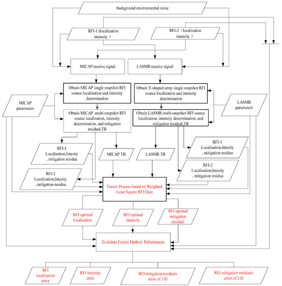
Figure 6.
Steps and verification process of the fusion method.
By using the weighted least square to fuse the localization and intensity determination results of the one-dimensional linear arrays and two-dimensional Y-shaped arrays, the accuracies of RFI source localization and intensity determination were further improved. The specific fusion steps were as follows.
(1) Different single-snapshot data, including the localization and intensity of the RFI source, were obtained by using the detection and localization method of two-dimensional Y-shaped arrays. The i-th set of data from the k-th RFI source was (), similarly obtaining multiple sets of constant intensity results, where the i-th set of data from the k-th RFI source was .
(2) Different single-snapshot data, including the localization and intensity of the RFI source, were obtained by using the detection and localization method of one-dimensional arrays. The i-th set of data from the k-th RFI source was ; similarly, multiple sets of constant intensity results were obtained, where the i-th set of data from the k-th RFI source was .
(3) According to Equations (2)–(7), the localization and intensity determination results of the fusion method were obtained by using datasets (1) and (2). The optimal estimate localization and intensity determination results of the fusion method were also obtained.
(4) According to Equations (8)–(10), the RFI source localization and intensity estimation results after data fusion were directly used for RFI mitigation. The mitigation residual was obtained by subtracting the brightness temperature image after mitigation RFI from the ideal background brightness temperature image. The mitigation residual of the fusion method was significantly reduced compared with the mitigation residual obtained by using MICAP and LASMR separately.
6. Results and Analysis
In this section, the experimental results under various conditions and the comparative experimental analysis are introduced, respectively.
6.1. Results
The results before and after the mitigation of case AA (450 K, 450 K) are shown in Figure 7, where “1-D array background BT image “ represents the brightness temperature distribution of MICAP under the background of the anechoic chamber. The “1-D array BT image of scene” represents the addition of RFI-1 and RFI-2 into the background of the anechoic chamber experiment. The “RFI mitigated TB image” represents using the step-by-step RFI detection and the step-by-step RFI localization methods [38,39,40,41,42] of RFI-1 and RFI-2 in the background of a anechoic chamber experiment, and using the CLEAN [19] method to mitigate RFI-1 and RFI-2. All other cases in this article used the same detection, localization, and mitigation method. The “Residual error image” represents the mitigation residual results of the scenario containing RFI and the scenario after RFI mitigation.
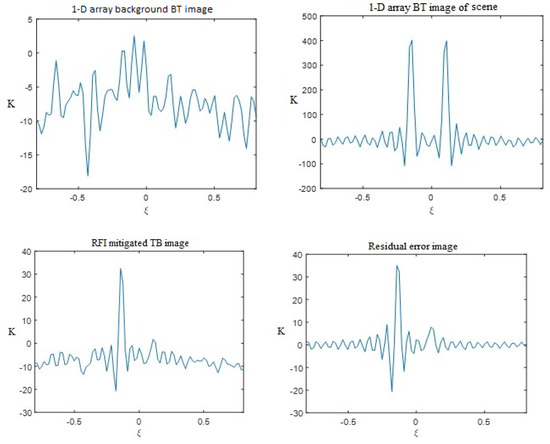
Figure 7.
Localization and mitigation effects of AA-distributed 1-D synthetic aperture background BT image, image of scene, RFI-mitigated TB image, and residual error image of MICAP for case AA.
The same RFI detection, localization, and mitigation method obtained an analysis of the pre- and post-mitigation results of the two-dimensional synthetic aperture radiometer, as shown in Figure 8.
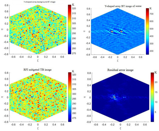
Figure 8.
Detection, localization, and mitigation effects of AA-distributed 2-D synthetic aperture background BT image, image of scene, RFI-mitigated TB image, and residual error image of LASMR for case AA.
The fusion method for MICAP and LASMR described in Chapter 5 was used to analyze the results before and after using the fusion method, as shown in Figure 9.
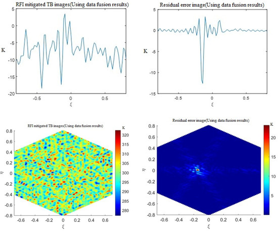
Figure 9.
Detection, localization, and mitigation effects of AA-distributed fusion method, RFI-mitigated TB image, and residual error image of MICAP for case AA. RFI-mitigated TB image and residual error image of LASMR for case AA.
The single one-dimensional synthetic aperture radiometer (MICAP) and two-dimensional synthetic aperture radiometer (LASMR) RFI detection, localization, and mitigation method, as well as the various localization information on RFI obtained using the fusion method, are shown in Figure 10.
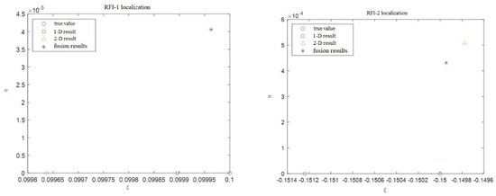
Figure 10.
Localization results of AA-distributed true value, 1-D result, 2-D result, and fusion result.
By processing through fusion methods, the location became more accurate, and the residual error was further reduced after mitigation. For example, the peak residual error before fusion for one-dimensional array fusion was 35 K, and the peak residual error after fusion was reduced to 13 K.
6.2. Comparison and Verification
According to the different energy distributions of RFI, MICAP, LASMR, and fusion methods were used to carry out RFI detection, RFI localization, and RFI suppression. The ξ and η dimension true location and detection error of RFI, the true intensity and detection error of RFI, and the suppression residual of RFI are shown in Table 3.

Table 3.
Detection, localization, and mitigation results under different experiment conditions.
The localization (true value ξ = 0.1) result errors of one-dimensional synthetic aperture radiometer, two-dimensional synthetic aperture radiometer, and the fusion method proposed in this article, obtained using the step-by-step localization method, are shown in Figure 11. The fusion method had improved localization accuracy compared with one-dimensional synthetic aperture radiometer. When weak sources existed, the fusion method improved the localization error compared with the two-dimensional synthetic aperture radiometer. When two moderate sources existed, the fusion method reduced the localization error compared with the two-dimensional synthetic aperture radiometer. When strong sources and extremely strong sources existed, the fusion method reduced less significant localization errors compared with the two-dimensional synthetic aperture radiometer.
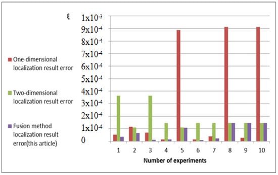
Figure 11.
Localization result errors of the three methods.
The determined RFI-1 intensity accuracy errors of the one-dimensional synthetic aperture radiometer, the two-dimensional synthetic aperture radiometer, and the fusion method proposed in this article are shown in Figure 12. The fusion intensity determination error was significantly reduced compared with the one-dimensional synthetic aperture radiometer. When strong sources and extremely strong sources existed, the fusion intensity determination error increased compared with the two-dimensional synthetic aperture radiometer.
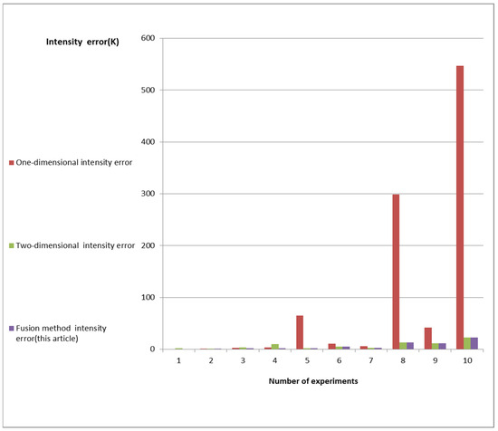
Figure 12.
Detection intensity errors of three methods.
Through the above 10 sets of the RFI experiment, it can be concluded that the minimum RFI mitigation residual range after the fusion of a one-dimensional synthetic aperture radiometer was 1.441 K, and the maximum value was 27.2677 K. The minimum RFI mitigation residual range before fusion of the one-dimensional synthetic aperture radiometer was 4.5906 K, and the maximum value was 56.5578 K, mainly affected by the energy distribution of RFI sources. For example, when weak sources and strong sources were distributed simultaneously, the mitigation residual of RFI was small, and when strong sources or extremely strong sources were distributed simultaneously, the mitigation residual of RFI was large, as shown in Figure 13.
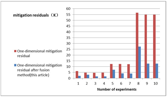
Figure 13.
Comparative analyses of mitigation residuals before and after fusion of one-dimensional synthetic aperture radiometer.
Through the analysis of the above 10 sets of RFI experiments, it can be concluded that the minimum RFI mitigation residual range after the fusion of the two-dimensional synthetic aperture radiometer was 0.5119 K, and the maximum value was 16.4704 K. The minimum RFI mitigation residual range before the fusion of the two-dimensional synthetic aperture radiometer was 0.6152 K, and the maximum value was 17.00328 K, mainly affected by the energy distribution of RFI sources. For example, when weak sources and strong sources were distributed simultaneously, the mitigation residual of RFI was small, and when strong sources or extremely strong sources were distributed simultaneously; the mitigation residual of RFI was large, as shown in Figure 14.
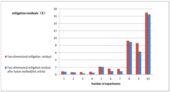
Figure 14.
Comparative analyses of mitigation residuals before and after fusion of two-dimensional synthetic aperture radiometer.
7. Conclusions
When two weak sources are combined, the fusion method improves the RFI localization accuracy and detection intensity accuracy, and reduces the mitigation residual errors. However, at this time, due to the significant influence of background noise on the one-dimensional arrays, the step-by-step RFI detection sequence changed, resulting in a larger detection intensity variance, and the fusion method detection intensity results tended to be biased towards the two-dimensional arrays’ results.
When combining weak sources and moderate sources, the fusion method improved RFI localization accuracy and detection intensity accuracy, and decreases mitigation residual errors. When a weak source was combined with a strong or extremely strong source, the RFI localization accuracy of the strong or extremely strong source processed by the fusion method was determined by the localization accuracy of the two-dimensional arrays. The localization accuracy of the weak source increased, the detection intensity accuracies of the two sources improved, and the mitigation residual error decreased. Due to the small influence of background noise on the two-dimensional arrays, the localization variance of the strong or extremely strong source was minimal.
When there were strong and extremely strong sources, the variance in the two-dimensional arrays’ localization dataset was minimal. The fusion localization results of this source were basically determined by the localization results of the two-dimensional arrays, but this does not mean that the mitigation residual error of the two-dimensional arrays was minimal. It can only indicate that background noise had little impact on the localization of the two-dimensional arrays at this time, resulting in almost identical localization results for each snapshot.
When two moderate-intensity sources were combined, as is similar to the case of weak sources, the detection intensity results of the fusion method tended to be biased towards the two-dimensional arrays’ results. The localization accuracy of the one-dimensional method improved and the localization accuracy of the two-dimensional method decreased, resulting in a smaller mitigation residual error. When a medium intensity source was combined with a strong or extremely strong source, similarly to a weak source, the localization accuracy of the strong source or extremely strong source processed by the fusion was determined by the localization accuracy of the two-dimensional arrays. The method localization accuracy of the moderate source increased, and the detection intensity accuracy of the two sources increased while the mitigation residual error decreased.
When two strong sources, two extremely strong sources, or a combination of strong sources and extremely strong sources were used, the localization accuracy of the fusion method was determined by the localization accuracy of the two-dimensional arrays. The detection intensity accuracy of the one-dimensional arrays was decreased. The detection intensity accuracy of the two-dimensional arrays was increased. The mitigation residual error was decreased.
In summary, the mitigation residual error of the fusion method can be reduced.
However, the fusion method using the least square criterion also has problems and shortcomings. The fusion method using the variance in one-dimensional and two-dimensional measurement data as their weights is not applicable. For example, when locating strong sources or extremely strong sources, if the influence of background noise can be ignored at this time, resulting in minimal variance in the localization results, then the fusion method can be dominated by the set of data. When two sources with the same intensity are combined, the order of step-by-step RFI detection changes under the influence of noise, resulting in a significant difference in the detection intensity of the same payload on the same RFI source. Continuing to use variance as the data fusion weight would then cause the fusion results to deteriorate.
In the future, some research and applications will be focused on the following areas. According to the characteristics of each snapshot, each data point in the dataset should be more appropriately weight to improve the accuracy and stability of the weighted fusion results. We should choose more suitable data fusion algorithms to improve the localization and intensity accuracies of fusion results. Developing new algorithms for different scenarios may require different data fusion methods. Suitable data fusion methods can be selected based on actual scenarios to improve the localization and intensity accuracies of the fusion results.
The method proposed in this article has been validated through real experiments in an anechoic chamber, and can be applied in orbit after the launch of the salinity satellite. Due to the ideal experimental environment described in this article, there will be complex environments such as ocean, land, and sea land in the future in orbit, and various parameters of the algorithm need to be modified and improved.
Author Contributions
Conceptualization, L.Z. and R.J.; methodology and validation, L.Z.; theory analysis, R.J., Q.Z., L.Z. and R.W.; investigation, H.Z. and Z.W.; writing—preparation, discussion, and editing, L.Z., R.J., Q.Z., R.W., H.Z. and Z.W; funding acquisition, R.J. and Q.Z. All authors have read and agreed to the published version of the manuscript.
Funding
This work was supported by the National Natural Science Foundation of China (funding number: 42276183, funding number: 42275141, and funding number: 62031005).
Data Availability Statement
The data are unavailable due to privacy.
Acknowledgments
The data of the anechoic chamber experiment were provided by the Institute of Remote Sensing Satellite, China Academy of Space Technology.
Conflicts of Interest
The authors declare no conflicts of interest.
References
- Zhang, Q.; Zhang, L.; Jia, Y.; Wang, B.; Li, S. Development and Prospect of Satellite Remote Sensing Technology for Ocean Dynamic Environment. J. Spacecr. Rocket. 2023, 60, 1679–1698. [Google Scholar] [CrossRef]
- Song, X.; Cui, X.; Zhai, Y.; Yan, J.; Duan, Z. Remote Sensing of Sea Surface Salinity and Temperature with Microwave Radiometers Research Review. Spacecr. Eng. 2021, 30, 108–114. [Google Scholar]
- Zhang, Q.; Yin, X.; Jiang, Y. Developing Sea Surface Salinity Satellite to Promote Ocean Dynamical Enviroments Observation. Spacecr. Eng. 2017, 26, 1–5. [Google Scholar] [CrossRef]
- Dinnat, E.P.; Le Vine, D.M.; Boutin, J.; Meissner, T.; Lagerloef, G. Remote Sensing of Sea Surface Salinity: Comparison of Satellite and In Situ Observations and Impact of Retrieval Parameters. Remote Sens. 2019, 11, 750. [Google Scholar] [CrossRef]
- Font, J.; Camps, A.; Borges, A.; Martin-Neira, M.; Boutin, J.; Reul, N.; Kerr, Y.H.; Hahne, A.; Mecklenburg, S. SMOS: The Challenging Sea Surface Salinity Measurement from Space. Proc. IEEE 2010, 98, 649–665. [Google Scholar] [CrossRef]
- Llorente, A.; Daganzo, E.; Oliva, R.; Uranga, E.; Kerr, Y.; Richaume, P.; de la Fuente, A.; Martin-Neira, M.; Mecklenburg, S. Lessons learnt from SMOS RFI activities after 10 years in orbit: RFI detection and reporting to claim protection and increase awareness of the interference problem in the 1400–1427 MHz passive band. In Proceedings of the RFI Workshop-Coexisting Radio Frequency Interference (RFI), Toulouse, France, 23–26 September 2019; pp. 1–6. [Google Scholar] [CrossRef]
- Skou, N.; Balling, J.E.; Søbjærg, S.S.; Kristensen, S.S. Surveys and analysis of RFI in the SMOS context. In Proceedings of the IEEE International Geoscience and Remote Sensing Symposium, Honolulu, HI, USA, 25–30 July 2010; pp. 2011–2014. [Google Scholar] [CrossRef]
- Uranga, E.; Llorente, A.; Oliva, R.; de la Fuente, A.; Daganzo, E.; Kerr, Y. Monitoring of SMOS RFI sources in the 1400–1427 MHz passive band. In Proceedings of the IGARSS 2018—2018 IEEE International Geoscience and Remote Sensing Symposium, Valencia, Spain, 22–27 July 2018; pp. 1241–1244. [Google Scholar] [CrossRef]
- Martín-Neira, M.; Oliva, R.; Corbella, I.; Torres, F.; Duffo, N.; Durán, I.; Kainulainen, J.; Closa, J.; Zurita, A.; Cabot, F.; et al. Lessons learnt from SMOS after 7 years in orbit. In Proceedings of the IEEE International Geoscience & Remote Sensing Symposium, Fort Worth, TX, USA, 23–28 July 2017. [Google Scholar] [CrossRef]
- Bringer, A.; Johnson, J.T.; Mohammed, P.N.; Misra, S.; Vine, D.L. Monitoring The L-Band RFI Environment: Tracking RFI Sources Observed by Smap. In Proceedings of the 2022 IEEE International Geoscience and Remote Sensing Symposium, IGARSS 2022, Kuala Lumpur, Malaysia, 17–22 July 2022; pp. 4240–4243. [Google Scholar] [CrossRef]
- de Matthaeis, P.; Le Vine, D. RFI detection and mitigation for Aquarius: Status and ongoing improvements. In Proceedings of the URSIGASS 2014, Beijing, China, 16–23 August 2014; pp. 1–3. [Google Scholar] [CrossRef]
- Li, Y.; Yin, X.; Zhou, W.; Lin, M.; Liu, H.; Li, Y. Performance Simulation of the Payload IMR and MICAP Onboard the Chinese Ocean Salinity Satellite. IEEE Trans. Geosci. Remote Sens. 2022, 60, 5301916. [Google Scholar] [CrossRef]
- Li, Y.; Yin, X.; Zhou, W.; Lin, M.; Ma, C.; Jin, R.; Liu, H.; Li, Y. Simulation Analysis of Payload IMR and MICAP Onboard Chinese Ocean Salinity Satellite. In Proceedings of the IGARSS 2020—2020 IEEE International Geoscience and Remote Sensing Symposium, Waikoloa, HI, USA, 26 September–2 October 2020; pp. 5635–5638. [Google Scholar] [CrossRef]
- Bin, L.; Dong, Z.; Fei, H. An improved RFI source detection method based on array factor property for synthetic aperture interferometric radiometer. In Proceedings of the SPIE, Microwave Remote Sensing: Data Processing and Applications II, Amsterdam, The Netherlands, 3–7 September 2023; Volume 12732, p. 1273206. [Google Scholar] [CrossRef]
- Jin, R.; Li, Q.; Liu, H. A Subspace Algorithm to Mitigate Energy Unknown RFI for Synthetic Aperture Interferometric Radiometer. IEEE Trans. Geosci. Remote Sens. 2020, 58, 227–237. [Google Scholar] [CrossRef]
- Oliva, R.; Nieto, S.; Felix, F. RFI detection algorithm: Accurate geolocation of the interfering sources in SMOS images. In Proceedings of the IEEE International Geoscience and Remote Sensing Symposium (IGARSS), Munich, Germany, 22–27 July 2012; pp. 3324–3326. [Google Scholar]
- Oliva, R.; Nieto, S.; Felix, F. RFI Detection Algorithm: Accurate Geolocation of the Interfering Sources in SMOS Images. IEEE Trans. Geosci. Remote Sens. 2013, 51, 4993–4998. [Google Scholar] [CrossRef]
- Castro, R.; Gutierrez, A.; Barbosa, J. A first set of techniques to detect radio frequency interferences and mitigate their impact on SMOS data. IEEE Trans. Geosci. Remote Sens. 2012, 50, 1440–1447. [Google Scholar] [CrossRef]
- Soldo, Y.; Cabot, F.; Khazaal, A.; Miernecki, M.; Słomińska, E.; Fieuzal, R.; Kerr, Y.H. Localization of RFI Sources for the SMOS Mission A Means for Assessing SMOS Pointing Performances. IEEE J. Sel. Top. Appl. Earth Obs. Remote Sens. 2015, 8, 617–627. [Google Scholar] [CrossRef]
- Park, H.; González-Gambau, V.; Camps, A.; Vall-Llossera, M. Improved MUSIC-Based SMOS RFI Source Detection and Geolocation Algorithm. IEEE Trans. Geosci. Remote Sens. 2016, 54, 1311–1322. [Google Scholar] [CrossRef]
- Li, J.; Hu, F.; He, F.; Wu, L. High-resolution RFI localization using covariance matrix augmentation in synthetic aperture interferometric radiometry. IEEE Trans. Geosci. Remote Sens. 2018, 56, 1186–1198. [Google Scholar] [CrossRef]
- Zhu, D.; Peng, X.; Li, G. A Matrix Completion Based Method for RFI Source Localization in Microwave Interferometric Radiometry. IEEE Trans. Geosci. Remote Sens. 2021, 59, 7588–7602. [Google Scholar] [CrossRef]
- Li, J.; Hu, F.; He, F.; Wu, L.; Peng, X.; Cheng, Y.; Zhu, D.; Chen, K. Super-resolution RFI localization with compressive sensing in synthetic aperture interferometric radiometers. In Proceedings of the IEEE International Geoscience and Remote Sensing Symposium (IGARSS), Milan, Italy, 26–31 July 2015; pp. 4734–4737. [Google Scholar] [CrossRef]
- Zhu, D.; Li, J.; Li, G. RFI Source Localization in Microwave Interferometric Radiometry: A Sparse Signal Reconstruction Perspective. IEEE Trans. Geosci. Remote Sens. 2020, 58, 4006–4017. [Google Scholar] [CrossRef]
- Camps, A.; Vall-Llossera, M.; Duffo, N.; Zapata, M.; Corbella, I.; Torres, F.; Barrena, V. Sun effects in 2-D aperture synthesis radiometry imaging and their cancelation. IEEE Trans. Geosci. Remote Sens. 2004, 42, 1161–1167. [Google Scholar] [CrossRef]
- Camps, A.; Bará, J.; Torres, F.; Corbella, I. Extension of the CLEAN technique to the microwave imaging of continuous thermal sources by means of aperture synthesis radiometers. J. Electromagn. Waves Appl. 1998, 12, 311–313. [Google Scholar] [CrossRef]
- Soldo, Y.; Khazaal, A.; Cabot, F.; Anterrieu, E.; Richaume, P. RFI mitigation for SMOS: A distributed approach. In Proceedings of the IEEE International Geoscience and Remote Sensing Symposium (IGARSS), Munich, Germany, 22–27 July 2012; pp. 3327–3330. [Google Scholar] [CrossRef]
- Soldo, Y.; Khazaal, A.; Cabot, F.; Richaume, P.; Anterrieu, E.; Kerr, Y.H. Mitigation of RFIs for SMOS: A Distributed Approach. IEEE Trans. Geosci. Remote Sens. 2014, 52, 7470–7479. [Google Scholar] [CrossRef]
- Hu, F.; Peng, X.; He, F.; Wu, L.; Li, J.; Cheng, Y.; Zhu, D. RFI Mitigation in Aperture Synthesis Radiometers Using a Modified CLEAN Algorithm. IEEE Geosci. Remote Sens. Lett. 2017, 14, 13–17. [Google Scholar] [CrossRef]
- Peng, X.; Hu, F.; He, F.; Zhu, D.; Cheng, Y.; Hu, H.; Zheng, T. An improved CLEAN algorithm for RFI Mitigation in Aperture Synthesis Radiometers. In Proceedings of the IEEE International Geoscience and Remote Sensing Symposium (IGARSS), Fort Worth, TX, USA, 23–28 July 2017; pp. 3448–3451. [Google Scholar] [CrossRef]
- Li, J.; Hu, F.; He, F.; Wu, L.; Peng, X. SMOS RFI mitigation using array factor synthesis of synthetic aperture interferometric radiometry. In Proceedings of the IEEE International Geoscience and Remote Sensing Symposium (IGARSS), Beijing, China, 10–15 July 2016; pp. 820–823. [Google Scholar] [CrossRef]
- Camps, A.; Park, H.; González-Gambau, V. An imaging algorithm for synthetic aperture interferometric radiometers with built-in RFI mitigation. In Proceedings of the IEEE Specialist Meeting on Microwave Radiometry and Remote Sensing of the Environment (MicroRad), Pasadena, CA, USA, 24–27 March 2014; pp. 39–43. [Google Scholar] [CrossRef]
- Li, J.; Hu, F.; He, F.; Wu, L.; Peng, X.; Zhu, D. An Imaging Method With Array Factor Synthesis in Synthetic Aperture Interferometric Radiometers. IEEE Geosci. Remote Sens. Lett. 2016, 13, 87–91. [Google Scholar] [CrossRef]
- Peng, X.; Hu, F.; He, F.; Wu, L.; Li, J.; Zhu, D.; Liao, Z.; Qian, C. RFI Mitigation of SMOS image based on CLEAN Algorithm. In Proceedings of the IEEE International Geoscience and Remote Sensing Symposium (IGARSS), Beijing, China, 10–15 July 2016; pp. 816–819. [Google Scholar] [CrossRef]
- Li, Y.; Zhang, W.; Zhang, J.; Zhang, L. Improved CLEAN Algorithm for RFI Mitigation of Aperture Synthesis Radiometer Images. IEEE Geosci. Remote Sens. Lett. 2022, 19, 4018105. [Google Scholar] [CrossRef]
- Li, Y.; Lin, M.; Yin, X.; Zhou, W. Analysis of the Antenna Array Orientation Performance of the Interferometric Microwave Radiometer (IMR) Onboard the Chinese Ocean Salinity Satellite. Sensors 2020, 20, 5396. [Google Scholar] [CrossRef] [PubMed]
- Liu, H.; Zhu, D.; Niu, L.; Wu, L.; Wang, C.; Chen, X.; Zhao, X.; Zhang, C.; Zhang, X.; Yin, X.; et al. MICAP (Microwave imager combined active and passive): A new instrument for Chinese ocean salinity satellite. In Proceedings of the 2015 IEEE International Geoscience and Remote Sensing Symposium (IGARSS), Milan, Italy, 26–31 July 2015; pp. 184–187. [Google Scholar] [CrossRef]
- Soldo, Y.; Le Vine, D.M. Characteristics of the RFI Environment at L-Band as Observed from SMAP; No. NASA/TM-20210000962; NASA: Washington, DC, USA, 2021. [Google Scholar]
- Corbella, I.; Duffo, N.; Vall-Llossera, M.; Camps, A.; Torres, F. The visibility function in interferometric aperture synthesis radiometry. IEEE Trans. Geosci. Remote Sens. 2004, 42, 1677–1682. [Google Scholar] [CrossRef]
- Gao, Y.; Zhou, W.; Zhang, L.; Zhang, H.; Jin, R.; Li, Q. A Combined RFI Localization Algorithm of BT Image and Subspace Decomposition for Synthetic Aperture Interferometric Radiometer. IEEE Trans. Geosci. Remote Sens. 2023, 61, 5301311. [Google Scholar] [CrossRef]
- Xu, Y.; Zhu, D.; Hu, F.; Fu, P. RFI Localization Using Jointly Non-Convex Low-Rank Approximation and Expanded Virtual Array in Microwave Interferometric Radiometry. IEEE Trans. Geosci. Remote Sens. 2023, 61, 5300515. [Google Scholar] [CrossRef]
- Park, H.; Camps, A. Accurate geolocation of RFI sources in SMOS imagery based on superresolution algorithms. In Proceedings of the IEEE Specialist Meeting on Microwave Radiometry and Remote Sensing of the Environment (MicroRad), Pasadena, CA, USA, 24–27 March 2014; pp. 29–32. [Google Scholar] [CrossRef]
Disclaimer/Publisher’s Note: The statements, opinions and data contained in all publications are solely those of the individual author(s) and contributor(s) and not of MDPI and/or the editor(s). MDPI and/or the editor(s) disclaim responsibility for any injury to people or property resulting from any ideas, methods, instructions or products referred to in the content. |
© 2024 by the authors. Licensee MDPI, Basel, Switzerland. This article is an open access article distributed under the terms and conditions of the Creative Commons Attribution (CC BY) license (https://creativecommons.org/licenses/by/4.0/).