
Investigation of Submerged MEMS Ultrasonic Sensors for Underwater Obstacle Avoidance Application

 ,
,  , ,
, ,
Abstract

1. Introduction
2. Working Principle
2.1. Parallel Plate Capacitor Model
2.2. Equivalent Circuit Model
3. Design and Simulation
4. Manufacturing Process
5. Testing and Characterization
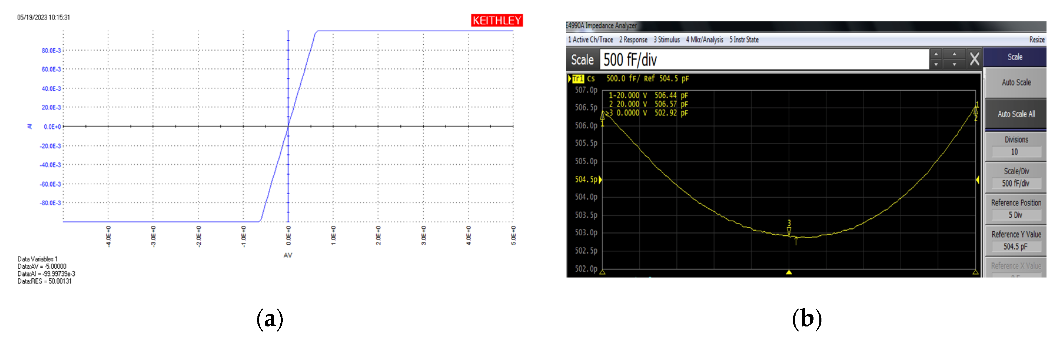
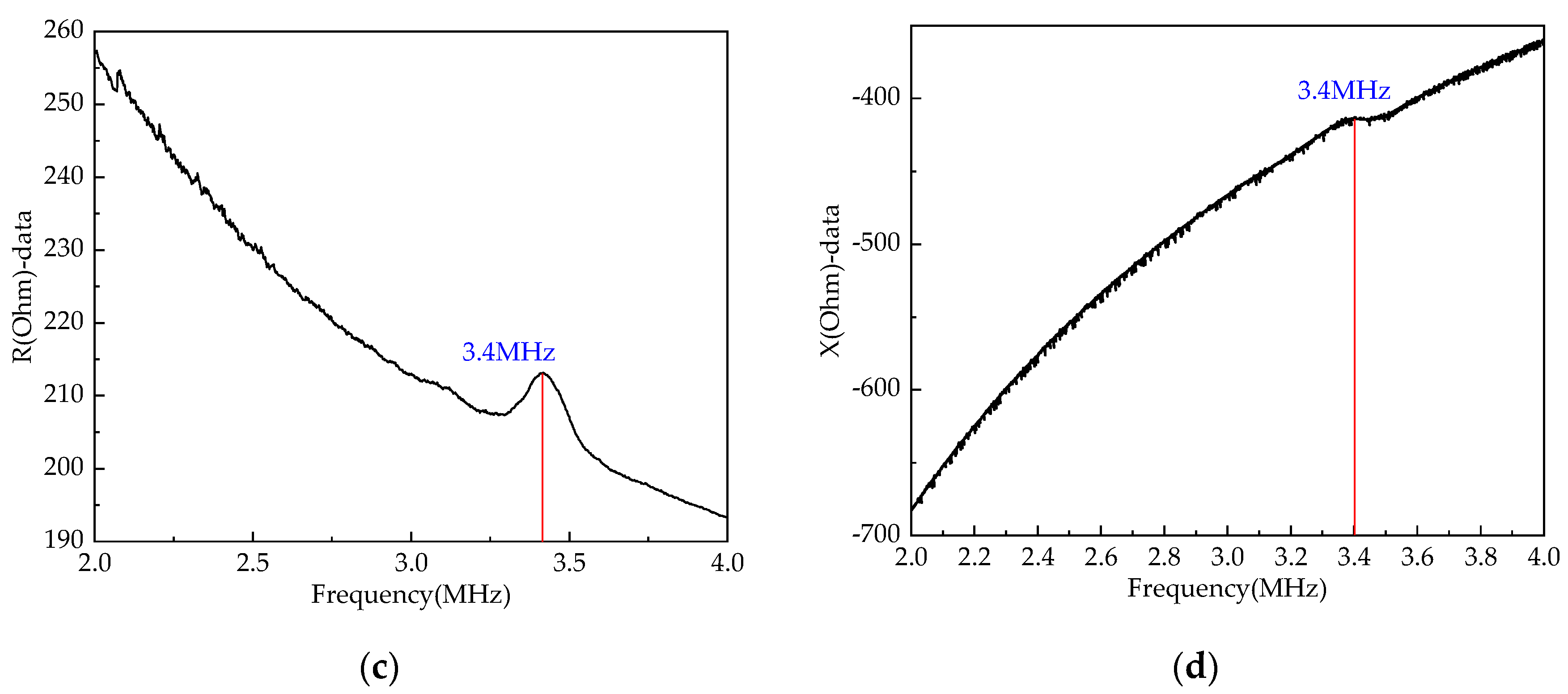
5.1. Electrical Testing
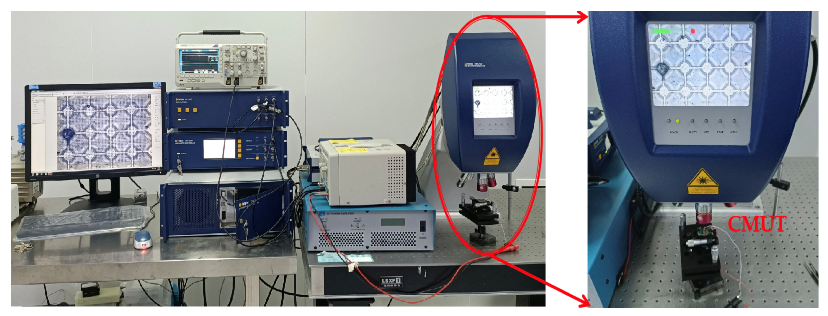
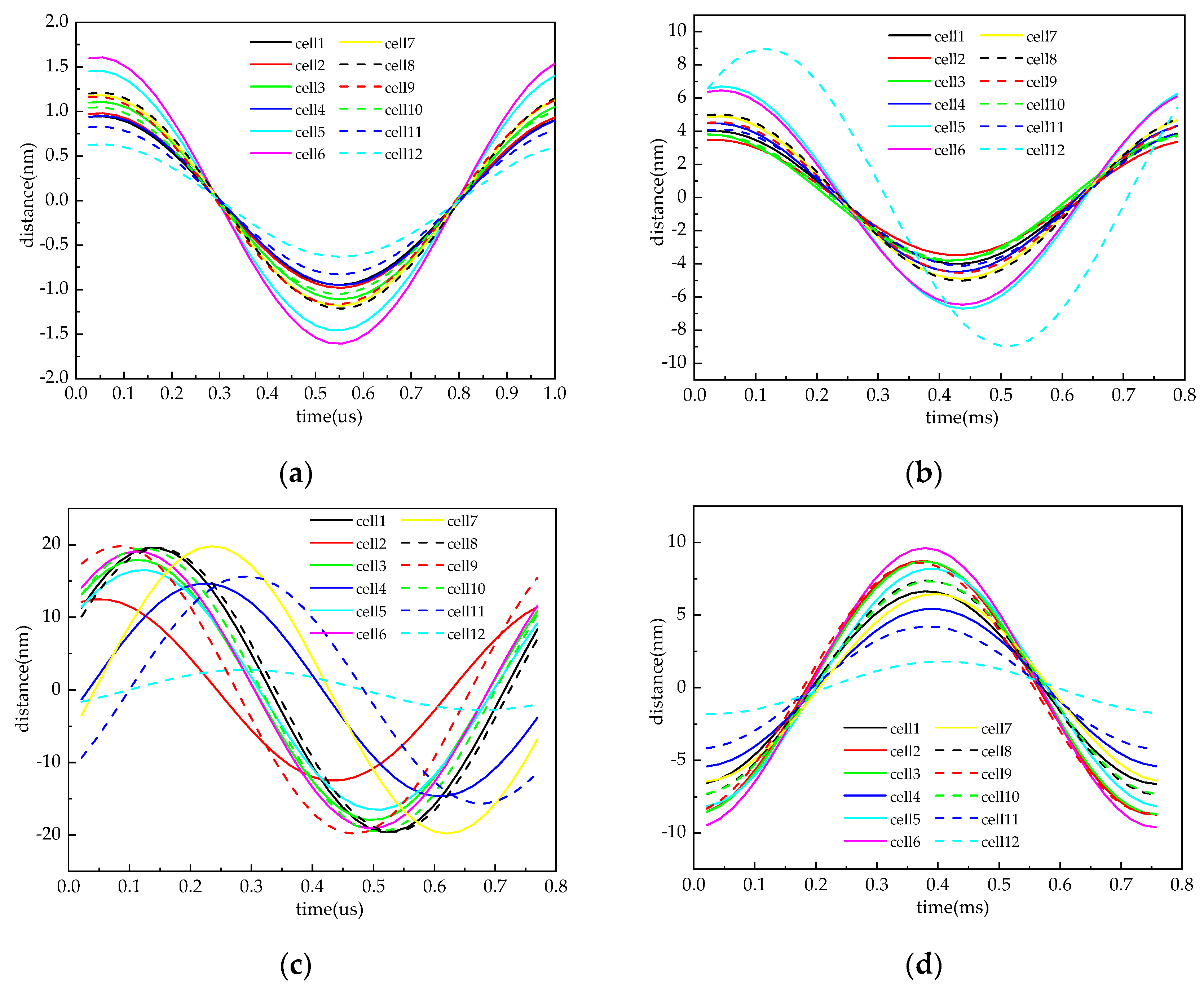
5.2. Vibration Testing
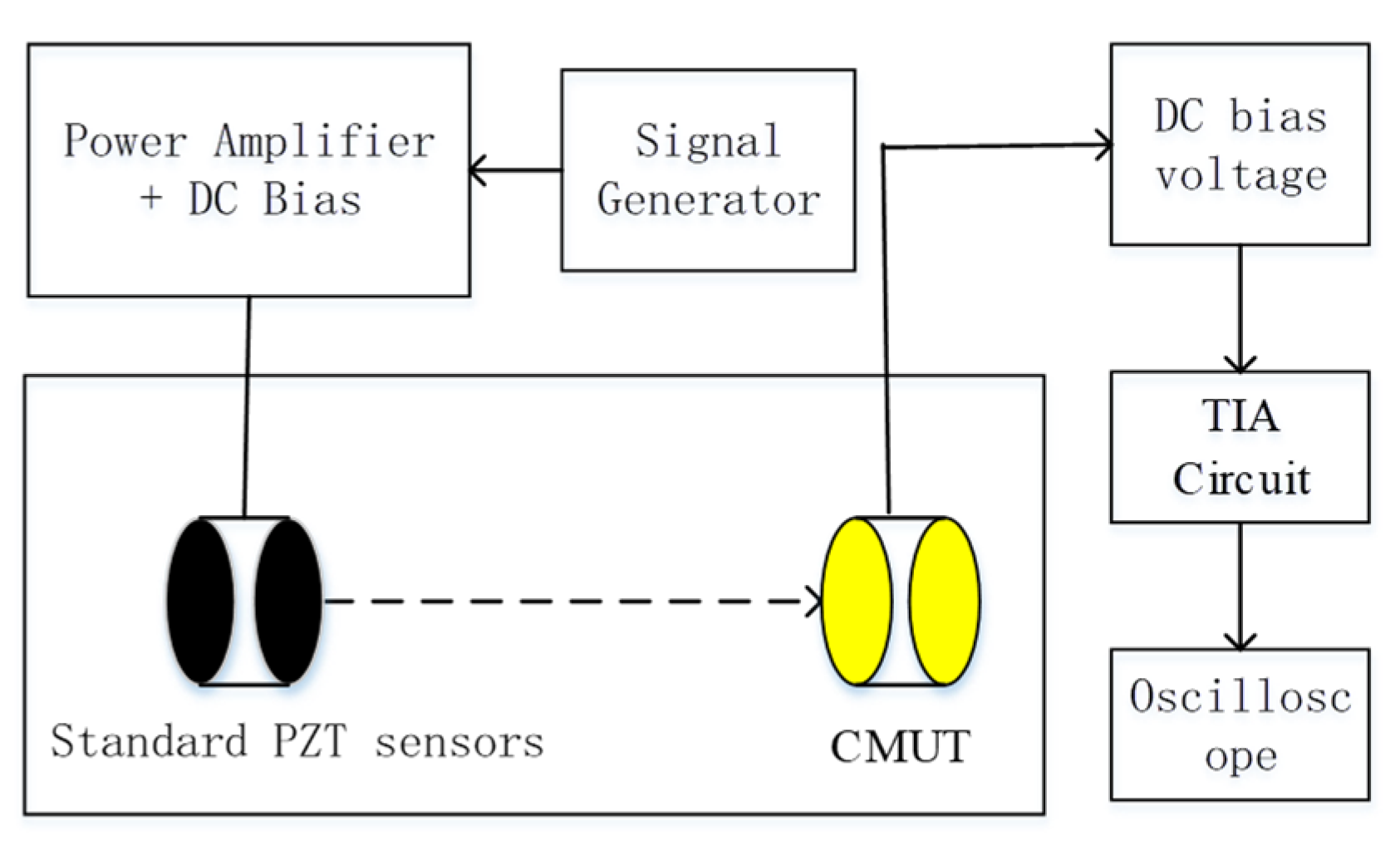
5.3. Submerged Environment Acoustic Testing and Characterization
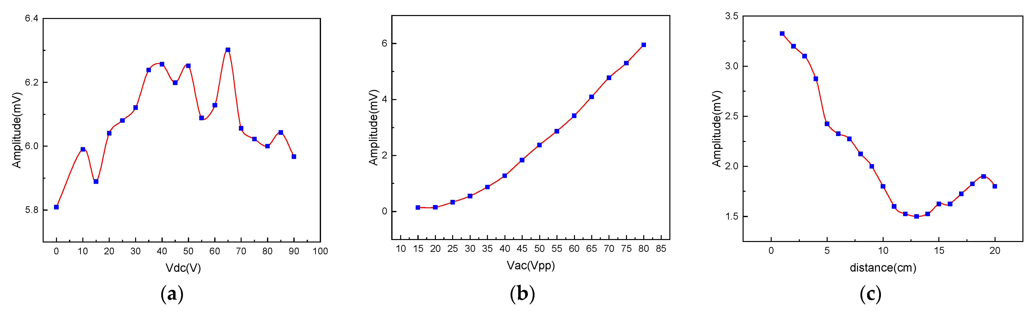
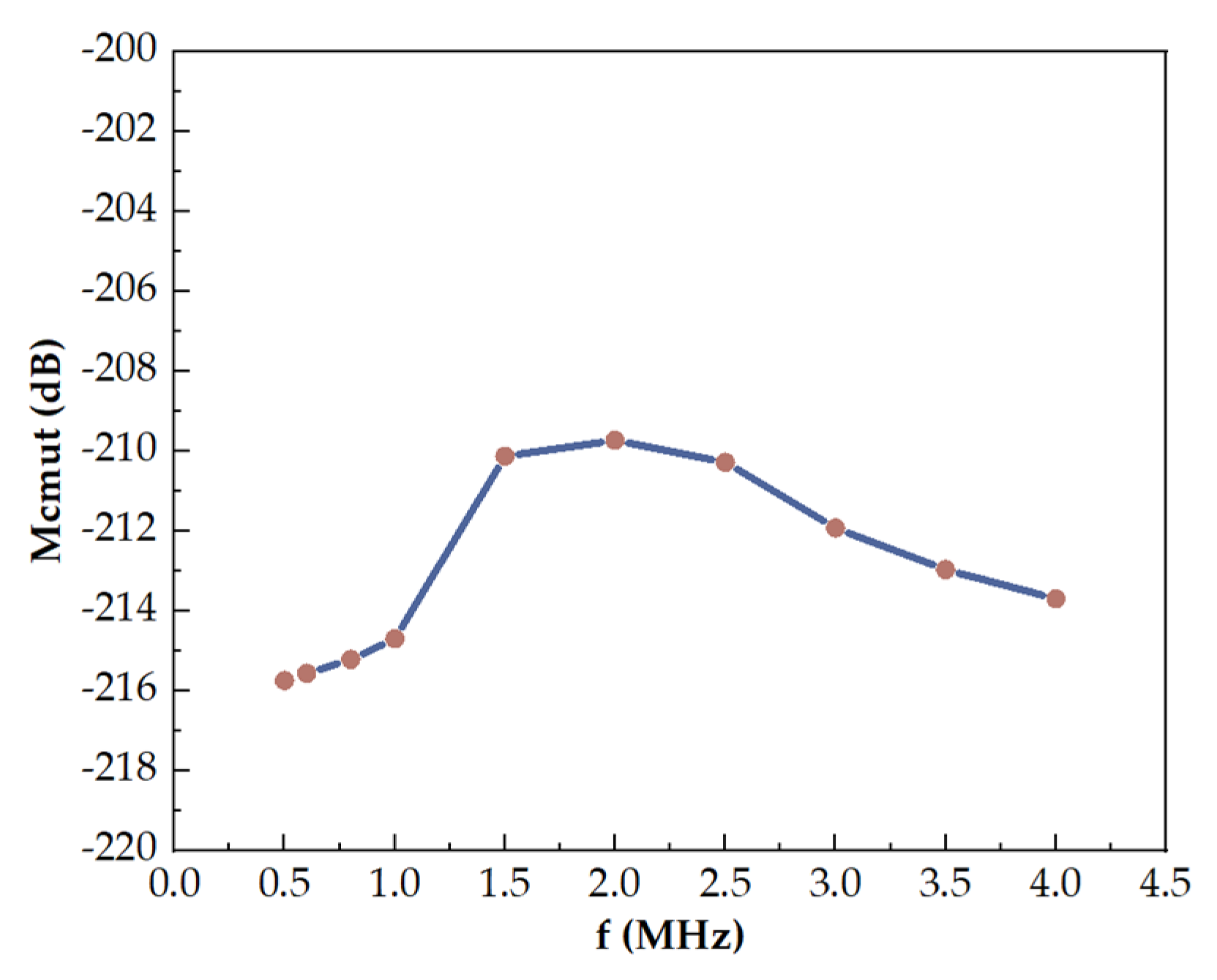
5.4. CMUT Receiver Response
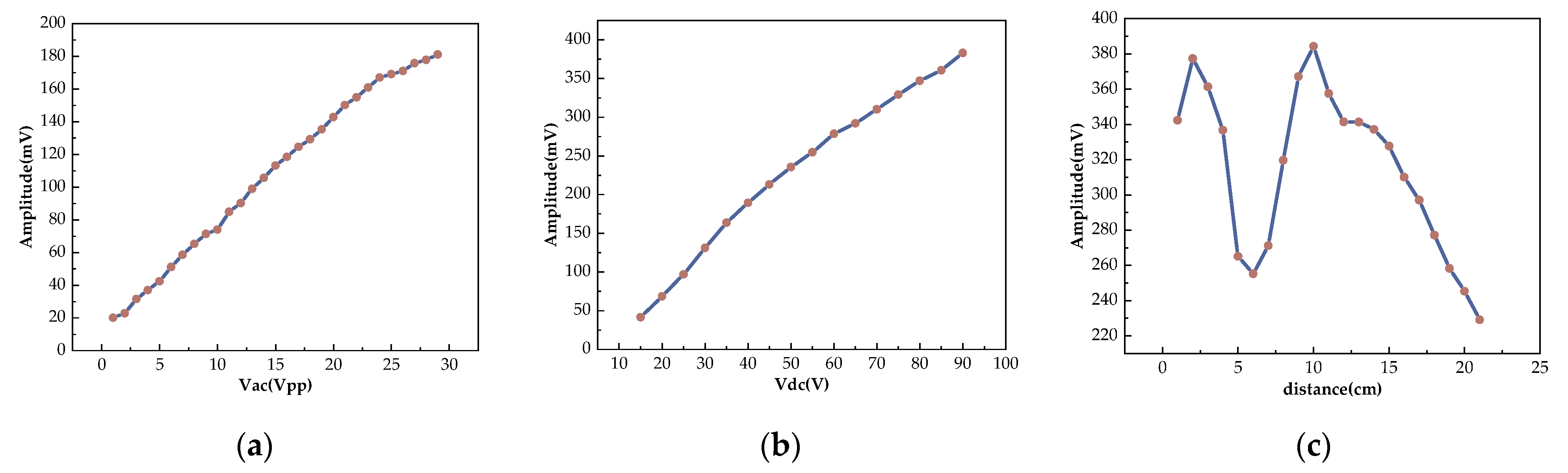
5.5. CMUT Transmission Response
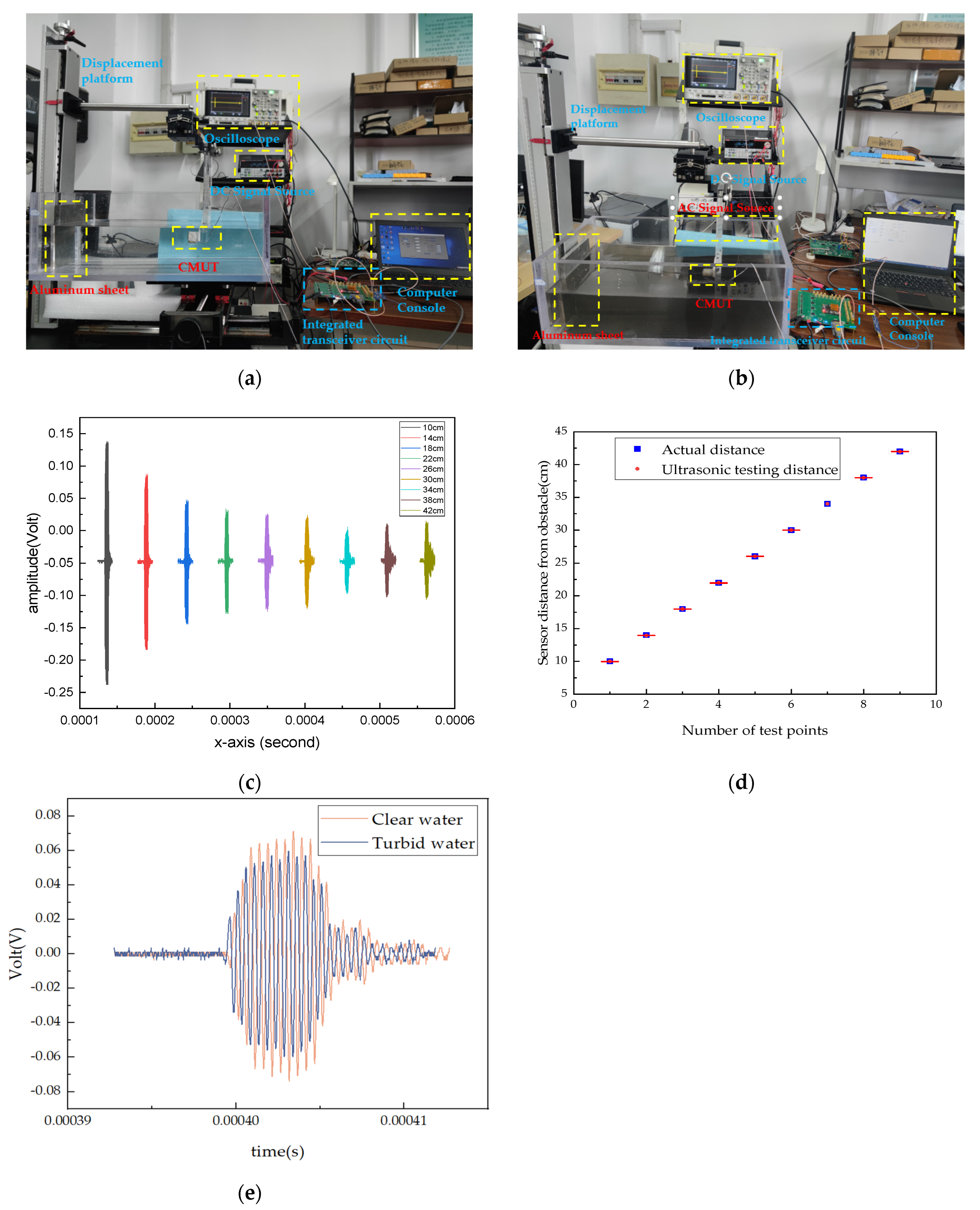
5.6. Underwater Directivity Experiment
5.7. Underwater Reflection Experiment
6. Discussion and Conclusions
Author Contributions
Funding
Data Availability Statement
Conflicts of Interest
References
- Braginsky, B.; Guterman, H. Obstacle Avoidance Approaches for Autonomous Underwater Vehicle: Simulation and Experimental Results. IEEE J. Ocean. Eng. 2016, 41, 882–892. [Google Scholar] [CrossRef]
- Lin, C.; Wang, H.; Yuan, J.; Yu, D.; Li, C. An improved recurrent neural network for unmanned underwater vehicle online obstacle avoidance. Ocean. Eng. 2019, 189, 106327. [Google Scholar] [CrossRef]
- Cao, X.; Ren, L.; Sun, C. Research on Obstacle Detection and Avoidance of Autonomous Underwater Vehicle Based on Forward-Looking Sonar. IEEE Trans. Neural Netw. Learn. Syst. 2022, 34, 9198–9208. [Google Scholar] [CrossRef] [PubMed]
- Li, C.; Guo, S.; Guo, J. Study on Obstacle Avoidance Strategy Using Multiple Ultrasonic Sensors for Spherical Underwater Robots. IEEE Sens. J. 2022, 22, 24458–24470. [Google Scholar] [CrossRef]
- Lu, M.; Chen, H.; Lu, P. Perception and Avoidance of Multiple Small Fast Moving Objects for Quadrotors with Only Low-Cost RGBD Camera. IEEE Robot. Autom. Lett. 2022, 7, 11657–11664. [Google Scholar] [CrossRef]
- Badrloo, S.; Varshosaz, M.; Pirasteh, S.; Li, J. A novel region-based expansion rate obstacle detection method for MAVs using a fisheye camera. Int. J. Appl. Earth Obs. Geoinf. 2022, 108, 102739. [Google Scholar] [CrossRef]
- Li, Y.; Ibanez-Guzman, J. Lidar for Autonomous Driving: The Principles, Challenges, and Trends for Automotive Lidar and Perception Systems. IEEE Signal Process. Mag. 2020, 37, 50–61. [Google Scholar] [CrossRef]
- Mandischer, N.; Eddine, S.C.; Huesing, M.; Corves, B. Radar SLAM for Autonomous Indoor Grinding. In Proceedings of the 2020 IEEE Radar Conference (RadarConf20), Florence, Italy, 21–25 September 2020; pp. 1–6. [Google Scholar]
- Khan, M.U.; Zaidi, S.A.A.; Ishtiaq, A.; Bukhari, S.U.R.; Samer, S.; Farman, A. A Comparative Survey of LiDAR-SLAM and LiDAR based Sensor Technologies. In Proceedings of the 2021 Mohammad Ali Jinnah University International Conference on Computing (MAJICC), Karachi, Pakistan, 15–17 July 2021; pp. 1–8. [Google Scholar]
- Adelegan, O.J.; Coutant, Z.A.; Wu, X.; Yamaner, F.Y.; Oralkan, Ö. Design and Fabrication of Wideband Air-Coupled Capacitive Micromachined Ultrasonic Transducers with Varying Width Annular-Ring and Spiral Cell Structures. IEEE Trans. Ultrason. Ferroelectr. Freq. Control 2021, 68, 2749–2759. [Google Scholar] [CrossRef]
- Wang, Z.; He, C.; Zhang, W.; Li, Y.; Gao, P.; Meng, Y.; Zhang, G.; Yang, Y.; Wang, R.; Cui, J.; et al. Fabrication of 2-D Capacitive Micromachined Ultrasonic Transducer (CMUT) Array through Silicon Wafer Bonding. Micromachines 2022, 13, 99. [Google Scholar] [CrossRef]
- Tong, Z.; Wu, Z.; Zhang, S.; Liu, H.; Lou, L. A Flexible Ultrasonic Sensor Based on Piezoelectric Micromachined Ultrasonic Transducers (pMUTs). In Proceedings of the 2021 22nd International Conference on Electronic Packaging Technology (ICEPT), Xiamen, China, 14–17 September 2021; pp. 1–4. [Google Scholar]
- Sadeghpour, S.; Kraft, M.; Puers, R. Design and fabrication strategy for an efficient lead zirconate titanate based piezoelectric micromachined ultrasound transducer. J. Micromechanics Microengineering 2019, 29, 125002. [Google Scholar] [CrossRef]
- Feng, G.H.; Liu, H.J.; Lai, G.R. Piezoelectric Micromachined Ultrasonic Transducer with a Universal Bottom-Up Fabrication Approach Implemented on a Foil as Doppler Radar for Gesture Recognition. In Proceedings of the 2019 IEEE 32nd International Conference on Micro Electro Mechanical Systems (MEMS), Seoul, Republic of Korea, 27–31 January 2019; pp. 779–782. [Google Scholar]
- Malik, A.N.; Rowland, J.; Haber, B.D.; Thom, S.; Jackson, B.; Volk, B.; Ehrman, R.R. The Use of Handheld Ultrasound Devices in Emergency Medicine. Curr. Emerg. Hosp. Med. Rep. 2021, 9, 73–81. [Google Scholar] [CrossRef] [PubMed]
- Haller, M.I.; Khuri-Yakub, B.T. A surface micromachined electrostatic ultrasonic air transducer. In Proceedings of the 1994 IEEE Ultrasonics Symposium, Cannes, France, 31 October–3 November 1994; Volume 1242, pp. 1241–1244. [Google Scholar]
- Soh, H.T.; Ladabaum, I.; Atalar, A.; Quate, C.F.; Khuri-Yakub, B.T. Silicon micromachined ultrasonic immersion transducers. Appl. Phys. Lett. 1996, 69, 3674–3676. [Google Scholar] [CrossRef]
- Huang, Y.; Ergun, A.S.; Haeggstrom, E.; Khuri-Yakub, B.T. Fabrication of Capacitive Micromachined Ultrasonic Transducers (CMUTs) using wafer bonding technology for low frequency (10 kHz–150 kHz) sonar applications. In Proceedings of the OCEANS’02 MTS/IEEE, Biloxi, MI, USA, 29–31 October 2002; Volume 2324, pp. 2322–2327. [Google Scholar]
- Park, K.K.; Lee, H.; Kupnik, M.; Khuri-Yakub, B.T. Fabrication of Capacitive Micromachined Ultrasonic Transducers via Local Oxidation and Direct Wafer Bonding. J. Microelectromechanic. Syst. 2011, 20, 95–103. [Google Scholar] [CrossRef]
- Yamaner, F.Y.; Zhang, X.; Oralkan, Ö. A three-mask process for fabricating vacuum-sealed capacitive micromachined ultrasonic transducers using anodic bonding. IEEE Trans. Ultrason. Ferroelectr. Freq. Control 2015, 62, 972–982. [Google Scholar] [CrossRef]
- Moini, A.; Nikoozadeh, A.; Choe, J.W.; Chang, C.; Stephens, D.N.; Sahn, D.J.; Khuri-Yakub, P.T. Fully integrated 2D CMUT ring arrays for endoscopic ultrasound. In Proceedings of the 2016 IEEE International Ultrasonics Symposium (IUS), Tours, France, 18–21 September 2016; pp. 1–4. [Google Scholar]
- Pang, D.-C.; Chang, C.-M. Development of a Novel Transparent Flexible Capacitive Micromachined Ultrasonic Transducer. Sensors 2017, 17, 1443. [Google Scholar] [CrossRef]
- Park, K.K.; Kupnik, M.; Lee, H.J.; Khuri-Yakub, B.T.; Wygant, I.O. Modeling and measuring the effects of mutual impedance on multi-cell CMUT configurations. In Proceedings of the 2010 IEEE International Ultrasonics Symposium, San Diego, CA, USA, 11–14 October 2010; pp. 431–434. [Google Scholar]
- Hsu, T.H.; Zope, A.A.; Li, M.H.; Li, S.S. A Compact Monolithic CMUT Receiver Front-End in a TiN-C CMOS-MEMS Platform. In Proceedings of the 2020 IEEE International Ultrasonics Symposium (IUS), Las Vegas, NV, USA, 7–11 September 2020; pp. 1–4. [Google Scholar]
- Danhua, Z.; Zhuang, S.; Daigle, R. A commercialized high frequency CMUT probe for medical ultrasound imaging. In Proceedings of the 2015 IEEE International Ultrasonics Symposium (IUS), Taiwan, China, 21–24 October 2015; pp. 1–4. [Google Scholar]
- Rezvanitabar, A.; Kilinc, M.S.; Tekes, C.; Arkan, E.F.; Ghovanloo, M.; Degertekin, F.L. An Adaptive Element-Level Impedance-Matched ASIC with Improved Acoustic Reflectivity for Medical Ultrasound Imaging. IEEE Trans. Biomed. Circuits Syst. 2022, 16, 492–501. [Google Scholar] [CrossRef]
- Yoon, H.S.; Chang, C.; Jang, J.H.; Bhuyan, A.; Choe, J.W.; Nikoozadeh, A.; Watkins, R.D.; Stephens, D.N.; Pauly, K.B.; Khuri-Yakub, B.T. Ex Vivo HIFU Experiments Using a 32 × 32-Element CMUT Array. IEEE Trans. Ultrason. Ferroelectr. Freq. Control 2016, 63, 2150–2158. [Google Scholar] [CrossRef]
- Pelenis, D.; Barauskas, D.; Vanagas, G.; Dzikaras, M.; Ultrasonics, D.V.J. CMUT-based biosensor with convolutional neural network signal processing. Ultrasonics 2019, 99, 105956. [Google Scholar] [CrossRef]
- Choi, W.Y.; Kwak, Y.S.; Park, K.K. Fingerprint Imaging System Based on Capacitive Micromachined Ultrasonic Transducer by Using Impediography Method Including Direct Touch and Waveguide Methods. IEEE Trans. Ultrason. Ferroelectr. Freq. Control 2019, 66, 402–411. [Google Scholar] [CrossRef]
- Anzinger, S.; Bretthauer, C.; Wasisto, H.S.; Dehé, A. Dual-Backplate CMUTs with Wide Bandwidth and Low Driving Voltage for Airborne Applications. IEEE Trans. Ultrason. Ferroelectr. Freq. Control 2023, 70, 1286–1294. [Google Scholar] [CrossRef]
- Wygant, I.O.; Kupnik, M.; Khuri-Yakub, B.T. Analytically calculating membrane displacement and the equivalent circuit model of a circular CMUT cell. In Proceedings of the 2008 IEEE Ultrasonics Symposium, Beijing, China, 2–5 November 2008; pp. 2111–2114. [Google Scholar]
- Auerswald, C.; Sorger, A.; Dienel, M.; Shaporin, A.; Mehner, J. MEMS acoustic emission sensor with mechanical noise rejection. In Proceedings of the International Multi-Conference on Systems, Signals & Devices, Chemnitz, Germany, 20–23 March 2012; pp. 1–6. [Google Scholar]
- Brenner, K.; Ergun, A.S.; Firouzi, K.; Rasmussen, M.F.; Stedman, Q.; Khuri-Yakub, B. Advances in Capacitive Micromachined Ultrasonic Transducers. Micromachines 2019, 10, 152. [Google Scholar] [CrossRef] [PubMed]
- Savoia, A.S.; Scaglione, G.; Haider, B. Combined use of Finite Element and Equivalent Circuit Modeling for System-Level Simulation of Integrated Capacitive Micromachined Ultrasonic Transducers (CMUT). In Proceedings of the 2020 IEEE International Ultrasonics Symposium (IUS), Las Vegas, NV, USA, 7–11 September 2020; pp. 1–4. [Google Scholar]
- Zhao, Y.; Zhao, L.; Barbruni, G.L.; Li, Z.; Jiang, Z.; Carrara, S. Equivalent Circuit Analysis of CMUTs-based Device for Measurement in Liquid Samples. In Proceedings of the 2021 IEEE International Symposium on Medical Measurements and Applications (MeMeA), Lausanne, Switzerland, 23–25 June 2021; pp. 1–5. [Google Scholar]
- Wang, H.; Ma, Y.; Yang, H.; Jiang, H.; Ding, Y.; Xie, H. MEMS Ultrasound Transducers for Endoscopic Photoacoustic Imaging Applications. Micromachines 2020, 11, 928. [Google Scholar] [CrossRef] [PubMed]
- Ray, A.; Sinha, S.; Haque, F.Z. Design of CMUT Cells for High-Intensity Focused Ultrasound Applications. In Proceedings of the 2022 IEEE International Conference of Electron Devices Society Kolkata Chapter (EDKCON), Kolkata, India, 26–27 November 2022; pp. 145–150. [Google Scholar]
- Bannon, F.D.; Clark, J.R.; Nguyen, C.T.C. High-Q HF microelectromechanical filters. IEEE J. Solid State Circuits 2000, 35, 512–526. [Google Scholar] [CrossRef]
- Wang, R.; Shen, W.; Zhang, W.; Song, J.; Li, N.; Liu, M.; Zhang, G.; Xue, C.; Zhang, W. Design and implementation of a jellyfish otolith-inspired MEMS vector hydrophone for low-frequency detection. Microsyst. Nanoeng. 2021, 7, 1. [Google Scholar] [CrossRef] [PubMed]
- Shim, H.; Roh, Y. Design and Fabrication of a Wideband Cymbal Transducer for Underwater Sensor Networks. Sensors 2019, 19, 4659. [Google Scholar] [CrossRef]
- Abdullah, Z.; Naz, S.; Raja, M.A.Z.; Zameer, A. Design of wideband tonpilz transducers for underwater SONAR applications with finite element model. Appl. Acoust. 2021, 183, 108293. [Google Scholar] [CrossRef]
- Xia, L.; Wang, H.; Huang, Q. Design and Fabrication of a Stacked Three-Phase Piezoelectric Composites Ring Array Underwater Ultrasound Transducer. Materials 2021, 14, 5971. [Google Scholar] [CrossRef]


| Parameters | Value |
|---|---|
| Cell diameter | 100 µm |
| Cell-to-cell distance | 20 µm |
| Silicon layer thickness in plate | 2 µm |
| Silicon oxide layer thickness in plate | 0.2 µm |
| Gap height | 0.3 µm |
| Metal thickness | 0.33 µm |
| Top metal diameter | 50 µm |
| Number of cells per element | 64 |
| Size of the element | 1000 µm × 1200 µm |
| Experiment | Media | Transmitting AC Signals (Vpp) | Emission DC Bias (Vdc) | Distance |
|---|---|---|---|---|
| Changing the DC bias voltage | water | 50 Vpp | 0–100 V | 2 cm |
| Change AC voltage | 10–80 Vpp | 30 V | 2 cm | |
| Change reception distance | 50 Vpp | 30 V | 1–20 cm |
| Experiment | Media | Emission Signal | Receiving DC | Distance |
|---|---|---|---|---|
| Varying the piezoelectric emission voltage | water | 2–30 Vpp | 30 V | 2 cm |
| Changing the DC bias voltage | 20 V | 15–90 V | 2 cm | |
| Changing the reception distance | 20 V | 60 V | 1–21 cm |
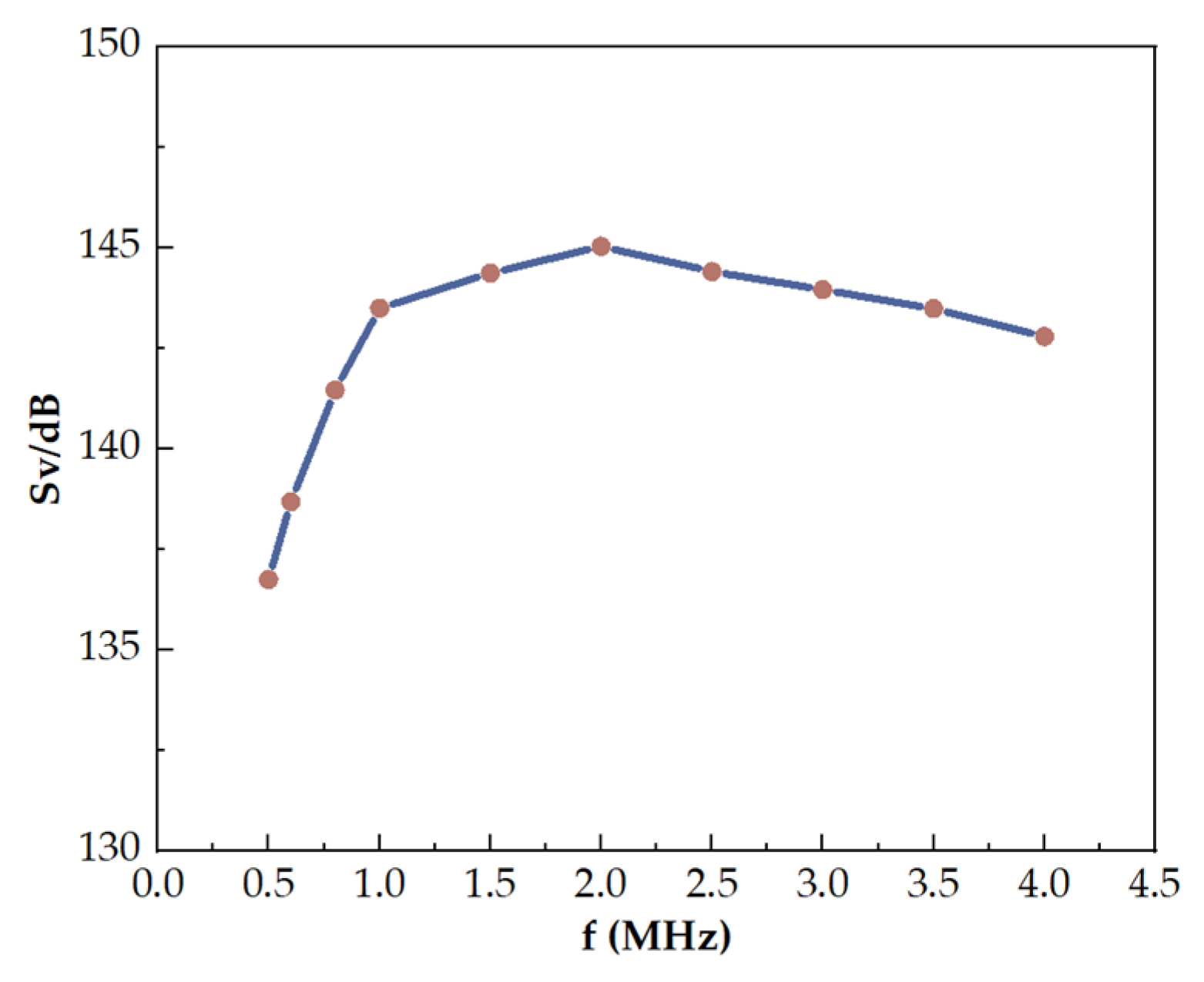
| f/kHz | SV/dB | f/kHz | SV/dB |
|---|---|---|---|
| 500.0 | 143.4 | 2500.0 | 176.8 |
| 600.0 | 150.4 | 2600.0 | 180.4 |
| 700.0 | 143.6 | 2700.0 | 183.3 |
| 800.0 | 149.3 | 2800.0 | 185.3 |
| 900.0 | 152.9 | 2900.0 | 186.2 |
| 1000.0 | 153.0 | 3000.0 | 186.7 |
| 1100.0 | 155.1 | 3100.0 | 186.9 |
| 1200.0 | 156.8 | 3200.0 | 185.1 |
| 1300.0 | 157.5 | 3300.0 | 182.7 |
| 1400.0 | 158.7 | 3400.0 | 180.3 |
| 1500.0 | 160.0 | 3500.0 | 177.6 |
| 1600.0 | 160.7 | 3600.0 | 176.0 |
| 1700.0 | 162.2 | 3700.0 | 174.3 |
| 1800.0 | 163.3 | 3800.0 | 173.2 |
| 1900.0 | 163.3 | 3900.0 | 172.6 |
| 2000.0 | 164.5 | 4000.0 | 171.9 |
| 2100.0 | 166.5 | 4100.0 | 171.6 |
| 2200.0 | 168.4 | 4200.0 | 171.1 |
| 2300.0 | 170.8 | 4300.0 | 171.0 |
| 2400.0 | 173.8 | 4400.0 | 171.0 |
| Frequency (MHz) | Measured Sensitivity (mV/MPa) |
|---|---|
| 0.30 | 723 |
| 0.35 | 802 |
| 0.40 | 858 |
| 0.45 | 906 |
| 0.50 | 1001 |
| 0.55 | 1085 |
| 0.60 | 1162 |
| 0.65 | 1204 |
| 0.70 | 1234 |
| 0.75 | 1281 |
| 0.80 | 1313 |
| 0.85 | 1360 |
| 0.90 | 1352 |
| 0.95 | 1422 |
| 1 | 1389 |
| 2 | 1096 |
| 3 | 1078 |
| 4 | 1012 |
| 5 | 1068 |
| 6 | 1100 |
Disclaimer/Publisher’s Note: The statements, opinions and data contained in all publications are solely those of the individual author(s) and contributor(s) and not of MDPI and/or the editor(s). MDPI and/or the editor(s) disclaim responsibility for any injury to people or property resulting from any ideas, methods, instructions or products referred to in the content. |
© 2024 by the authors. Licensee MDPI, Basel, Switzerland. This article is an open access article distributed under the terms and conditions of the Creative Commons Attribution (CC BY) license (https://creativecommons.org/licenses/by/4.0/).
Share and Cite
Wang, Z.; Zhang, W.; Wang, R.; He, C.; Liu, S.; Wang, J.; Li, Z.; Lu, X.; Qin, Y.; Zhang, G.; et al. Investigation of Submerged MEMS Ultrasonic Sensors for Underwater Obstacle Avoidance Application. Remote Sens. 2024, 16, 497. https://doi.org/10.3390/rs16030497
Wang Z, Zhang W, Wang R, He C, Liu S, Wang J, Li Z, Lu X, Qin Y, Zhang G, et al. Investigation of Submerged MEMS Ultrasonic Sensors for Underwater Obstacle Avoidance Application. Remote Sensing. 2024; 16(3):497. https://doi.org/10.3390/rs16030497
Chicago/Turabian StyleWang, Zhihao, Wendong Zhang, Renxin Wang, Changde He, Shurui Liu, Jingwen Wang, Zhaodong Li, Xiaoxing Lu, Yun Qin, Guojun Zhang, and et al. 2024. "Investigation of Submerged MEMS Ultrasonic Sensors for Underwater Obstacle Avoidance Application" Remote Sensing 16, no. 3: 497. https://doi.org/10.3390/rs16030497
APA StyleWang, Z., Zhang, W., Wang, R., He, C., Liu, S., Wang, J., Li, Z., Lu, X., Qin, Y., Zhang, G., Cui, J., Yang, Y., & Jia, L. (2024). Investigation of Submerged MEMS Ultrasonic Sensors for Underwater Obstacle Avoidance Application. Remote Sensing, 16(3), 497. https://doi.org/10.3390/rs16030497