Article

An Integrity Monitoring Method for Navigation Satellites Based on Multi-Source Observation Links

1
Beijing Satellite Navigation Center, Beijing 100094, China
2
Shanghai Astronomical Observatory, Shanghai 200030, China
*
Author to whom correspondence should be addressed.
Remote Sens. 2024, 16(23), 4574; https://doi.org/10.3390/rs16234574
Submission received: 31 October 2024 / Revised: 4 December 2024 / Accepted: 5 December 2024 / Published: 6 December 2024

Abstract

:
The BeiDou-3 navigation satellite system (BDS-3) has officially provided positioning, navigation, and timing (PNT) services to global users since 31 July 2020. With the application of inter-satellite link technology, global integrity monitoring becomes possible. Nevertheless, the content of integrity monitoring is still limited by the communication capacity of inter-satellite links and the layout of ground monitoring stations. Low earth orbit (LEO) satellites have advantages in information-carrying rate and kinematic velocity and can be used as satellite-based monitoring stations for navigation satellites. Large numbers of LEO satellites can provide more monitoring data than ground monitoring stations and make it easier to obtain full-arc observation data. A new challenge of redundant data also arises. This study constructs multi-source observation links with satellite-to-ground, inter-satellite, and satellite-based observation data, proposes an integrity monitoring method with optimization of observation links, and verifies the performance of integrity monitoring with different observation links. The experimental results show four findings. (1) Based on the integrity status of BDS-3, the proposed system-level integrity mode can realize full-arc anomaly diagnosis in information and signals according to the observation conditions of the target satellite. Apart from basic navigation messages and satellite-based augmentation messages, autonomous messages and inter-satellite ranging data can be used to evaluate the state of the target satellite. (2) For a giant LEO constellation, only a small number of LEO satellites need to be selected to construct a minimum satellite-based observation unit that can realize multiple returns of navigation messages and reduce the redundancy of observation data. With the support of 12 and 30 LEO satellites, the minimum number of satellite-based observation links is 1 and 4, respectively, verifying that a small amount of LEO satellites could be used to construct a minimum satellite-based observation unit. (3) A small number of LEO satellites can effectively improve the observation geometry of the target satellite. An orbit determination observation unit, which consists of chosen satellite-to-ground and/or satellite-based observation links based on observation geometry, is proposed to carry out fast calculations of satellite orbit. If the orbit determination observation unit contains 6 satellite-to-ground monitoring links and 6/12/60 LEO satellites, the value of satellite position dilution of precision (SPDOP) is 38.37, 24.60, and 15.71, respectively, with a 92.95%, 95.49%, and 97.12% improvement than the results using 6 satellite-to-ground monitoring links only. (4) LEO satellites could not only expand the resolution of integrity parameters in real time but also augment the service accuracy of the navigation satellite system. As the number of LEO satellites increases, the area where UDRE parameters can be solved in real time is constantly expanding to a global area. The service accuracy is 0.93 m, 0.88 m, and 0.65 m, respectively, with augmentation of 6, 12, and 60 LEO satellites, which is an 8.9%, 13.7%, and 36.3% improvement compared with the results of regional service. LEO satellites have practical application values by improving the integrity monitoring of navigation satellites.

1. Introduction

The BeiDou-3 navigation satellite system (BDS-3) has been officially providing high-accuracy positioning, navigation, and timing services to global users since 31 July 2020. The positioning accuracy has been improved from the submeter level to the centimeter level, which has basically solved the problem of high-accuracy positioning. With the expansion of satellite navigation applications to emerging fields, such as unmanned autonomous operating systems, intelligent driving, and automated precision operations, demand has gradually changed from requiring high accuracy to high integrity.
Integrity parameters are significant and fundamental performance indexes to predict the application security of navigation satellite systems. The definition of integrity has been constantly improved by updating the navigation system [1]. The existing technology for integrity monitoring is mainly designed with alarm limits at the meter level based on the positioning accuracy at the meter or submeter level and is not fully adapted to high-precision positioning technology.
BDS-3 has adopted a new design concept for integrity parameters, which takes full consideration of compatibility and interoperation with BDS-2 and references the modern design of CNAV-2 and F/NAV messages [1,2,3]. Based on the integrated design of the basic navigation service and satellite-based augmentation service in BDS-3, integrity parameters can be divided into two types: basic integrity parameters and augmentation integrity parameters. Diversified design can not only improve the reliability of system integrity monitoring but also reduce the cost of different users.
Basic integrity parameters are solved with satellite-to-ground and inter-satellite observation data to indicate the state of navigation satellites in real time and in the short term and long term. These messages can be modulated and broadcast in new signals (B1C and B2a) and transitional signals (B1I and B3I) [4,5,6,7] to global users with the support of satellite-to-ground and inter-satellite observation links. As deployment limitations of monitoring stations and constraints on the communication capacity of inter-satellite links, real-time integrity monitoring within a global area is rather difficult to realize.
Augmentation integrity parameters are generated by the BDS-3 satellite-based augmentation system (BDSBAS), which can realize real-time monitoring at the second level with the support of satellite-to-ground observation links. Only regional users in China and surrounding areas can obtain augmentation monitoring service.
With the comprehensive positioning, navigation, and timing (PNT) concept proposed [8], research on low earth orbit (LEO) constellations as a backup and augmentation system for the global navigation satellite system (GNSS) has garnered increasing attention both domestically and internationally. An increasing number of LEO satellites are being equipped with high-precision satellite-based GNSS monitoring receivers [9,10,11,12]. The proliferation of LEO satellites will facilitate the acquisition of full-arc navigation satellite observation data, thereby significantly enhancing real-time monitoring capabilities. Nevertheless, it also poses challenges related to excessive observational data. Consequently, combined utilization of satellite-to-ground, inter-satellite, and satellite-based observation links will be crucial for achieving real-time monitoring data to enhance the systematic capability of integrity monitoring.
This study first constructs multi-source observation links with satellite-to-ground, inter-satellite, and satellite-based observation data. Then, an optimization method of observation links is proposed to realize the constrained return of navigation messages and rapid calculation of satellite orbit. Finally, integrity monitoring capacity is evaluated with different observation links to verify the feasibility of improving the integrity monitoring capability of BDS-3.

2. Systematic Integrity Design for BDS-3 Satellite

2.1. Integrity Monitoring System of BDS-3

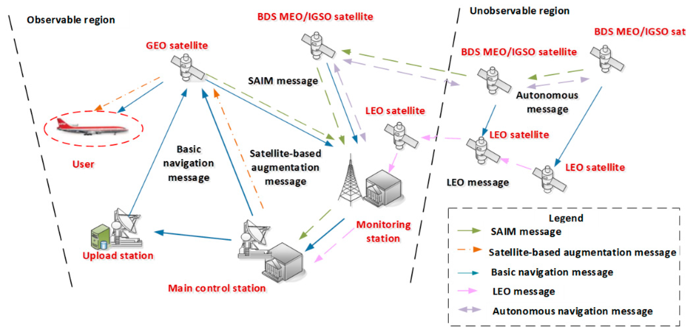
Regarding integrity monitoring of the target satellite, the main control station of BDS-3 should collect satellite-to-ground and inter-satellite observation data to obtain the pseudo-range and satellite autonomous integrity monitoring (SAIM) information, evaluate the state of the satellite, and generate various integrity indicator messages. These messages can be broadcast to the users through basic navigation messages and satellite-based augmentation messages. Different types of users in different regions can receive different integrity monitoring services. The process of integrity monitoring for BDS-3 is shown in Figure 1.
Basic integrity parameters broadcast in basic navigation messages and SAIM messages mainly include the healthy indicator (SatH1), healthy status (HS), healthy indicator (Hea or Health), regional user range accuracy indicator (RURAI), signal-in-space accuracy indicator (SISAI), signal-in-space monitoring accuracy indicator (SISMAI), integrity flag of data (DIF), integrity flag of signal (SIF), and integrity flag of alarm (AIF).
Augmentation integrity parameters broadcast in satellite-based augmentation messages mainly included user differential range error indicator (UDREI), grid-point ionospheric vertical delay error index (GIVEI), dual frequency range error indicator (DFREI), and dual frequency range error change indicator (DFRECI).
Parameters have different update cycles and broadcast strategies, as shown in Table 1. HS and SIF can be generated not only by the main control station but also by the satellite itself with the application of SAIM technology.

2.2. Limitation of the Integrity Monitoring System

Compared with BDS-2, the service area and timeliness of integrity monitoring for BDS-3 have been greatly improved. Nevertheless, the generation of integrity parameters is still limited by valid observation data. The limitations are mainly reflected as follows:
(1)
Layout of ground monitoring stations
BDS-3 has deployed dozens of ground monitoring stations in China and surrounding areas. The daily tracking and monitoring arc rate of the medium earth orbit (MEO) satellite is less than 40%. Most integrity parameters could not be generated as the satellite leaves the monitoring area. The current layout of ground monitoring stations could not support the real-time calculation of integrity parameters.
(2)
Communication capacity of inter-satellite links
BDS-3 has constructed a dynamic inter-satellite network to realize rapid distribution and return of information throughout the whole constellation. A limitation of communication capacity is that navigation messages could not be returned to the main control station except for the parameters of SIF. Furthermore, the inbound rate of inter-satellite observation data within inter-satellite planning was only about 95% [13], and the average age of data (AOD) for MEO satellites was 1.07 h [14], meaning that there was a certain absence of observation data through the inter-satellite links and cannot guarantee real-time transmission of all information correctly.
(3)
Monitoring content of systematic integrity
Systematic integrity for navigation satellites mainly relies on pseudo-range and regional navigation messages through satellite-to-ground observation links. Some data that can effectively identify the service status of a satellite, such as full-arc returned navigation messages, autonomous navigation messages [15], and inter-satellite observation data, are not fully applied in integrity monitoring.

3. Design of Integrity Monitoring System with Multi-Source Observation Links

3.1. Demand Analysis

LEO satellites can be used as satellite-based monitoring stations for navigation satellites to make up for the limitations mentioned above. The advantages of LEO satellites for BDS-3 monitoring can be reflected in the following aspects.
(1)
Extending monitoring area
At present, approximately 60% of daily messages from the MEO satellite cannot be returned to the main control station due to the limited layout of ground monitoring stations. LEO satellites have characteristics of a high kinematic velocity and information-carrying rate, making it possible to realize multi-tracking of the full-arc satellite and extend monitoring content. Based on the communication ability of LEO satellites, messages can be returned at the minute level, or even the second level, no matter where the navigation satellite is.
(2)
Improving availability of integrity parameters
Calculation of integrity parameters, which can indicate the accuracy of service, usually needs observation data collected by ground monitoring stations. With the support of LEO satellites, more observation data can be gained to participate in the calculation of integrity parameters, making it possible to globally realize real-time broadcasting of integrity parameters. Moreover, the accuracy of signal-in-space could be obviously improved when the orbits of navigation satellites and LEO satellites are synchronously determined [16]. The accuracy of corresponding integrity parameters will also be improved, thus improving the indication accuracy of the navigation service.
Therefore, constructing multi-source observation links with the support of ground monitoring stations and LEO satellites has great significance in breaking through the bottleneck of existing technology and effectively improves reliability and continuity of integrity monitoring.

3.2. System Composition

This study proposes an integrity monitoring system with the support of multi-source observation links, which consist of satellite-to-ground, inter-satellite, and satellite-based observation links. As shown in Figure 2, the system can make comprehensive use of satellite-to-ground, inter-satellite, and satellite-based observation data, basic navigation messages, satellite-based augmentation messages, autonomous navigation messages, and other integrity-related monitoring information.
Satellite-to-ground observation links are mainly used to gain observation data from satellites and broadcast basic and satellite-based augmentation messages to satellites. The corresponding stations consist of the main control station, upload stations, and monitoring stations. All observation data and returned messages should be collected and gathered in the main control station. Then, basic and augmentation integrity parameters can be generated and broadcast through satellite-to-ground and inter-satellite links.
Inter-satellite observation links are mainly used to gain pseudo-ranging data and autonomous navigation messages. The pseudo-ranging data can not only be integrated with other observations to support the calculation of integrity parameters but also be used to estimate the state of chained signals. Results of autonomous orbit determination and clock accuracy can be used to estimate the operating state of the satellite.
Satellite-based monitoring links are mainly used to gain observation data and basic integrity monitoring messages of navigation satellites to the main control station.

3.3. Optimization Strategies of Observation Links

Large numbers of LEO satellites can make it easier to obtain full-arc observation data but also bring new problems of excess data. Optimizing strategies should be proposed to improve monitoring efficiency for navigation satellites. This study proposes concepts of minimum satellite-based observation unit and orbit determination observation unit.
(1)
Minimum satellite-based observation unit
The minimum satellite-based observation unit consists of chosen satellite-based observation links that can realize on-demand return of navigation messages. The construction process is as follows.
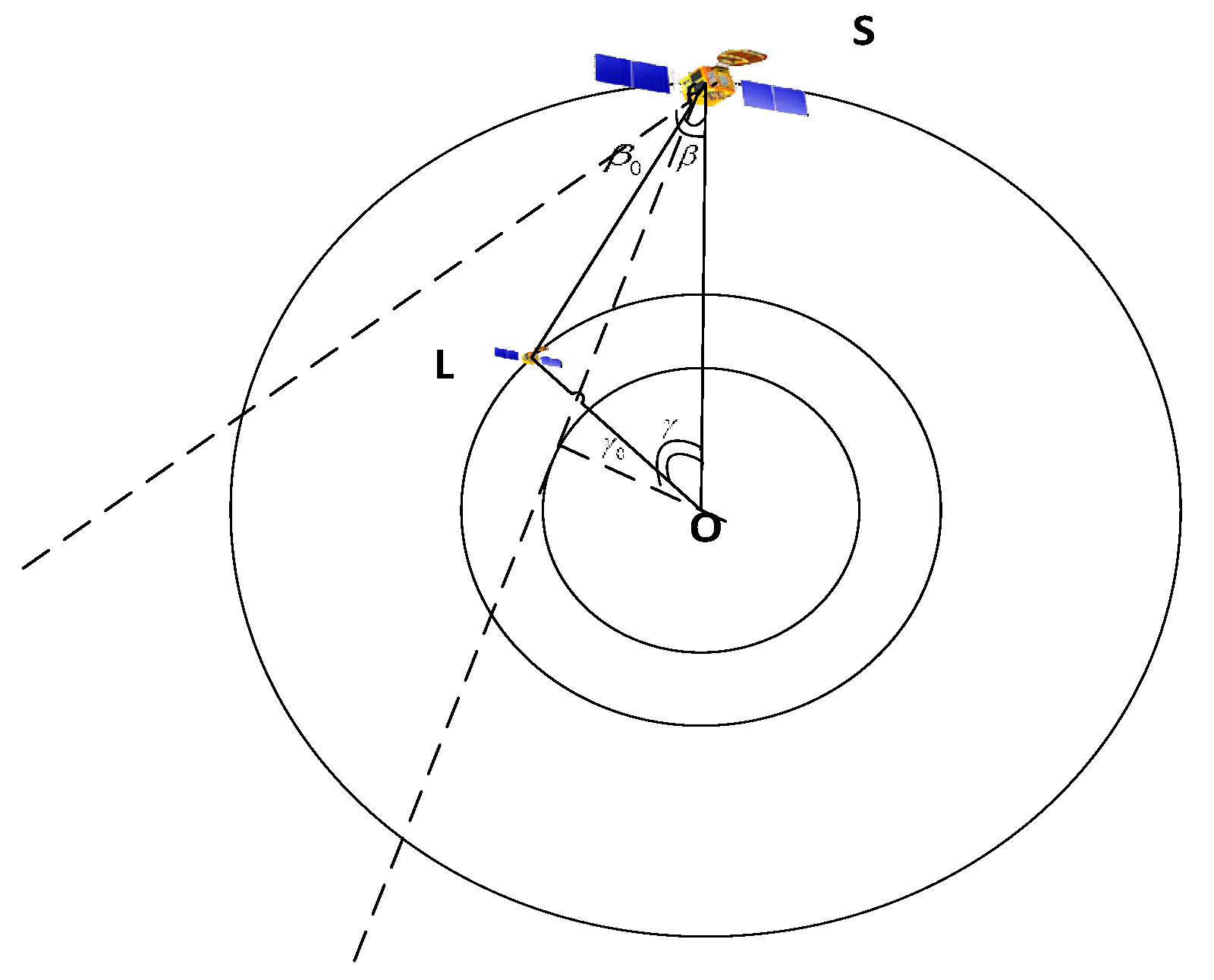
Firstly, the observation effectiveness of LEO satellites to target satellites should be evaluated. Distance R O S between the target satellite and the geocenter, Distance R O L between the LEO satellite and the geocenter, and distance R S L between the target satellite and the LEO satellite can be gained through ephemeris of the LEO satellite and target satellite. The angle β could be described as follows:
β = arccos R S L 2 + R O S 2 R O L 2 2 R S L R O S
As shown in Figure 3, when angle γ between R O L and R O S is no more than angle γ 0 which is the angle between horizontal sight point-to-geocenter line and R O S , the satellite-based observation link is valid if β is less than angle β 0 . Angle β 0 is the half-beam angle of the target satellite.
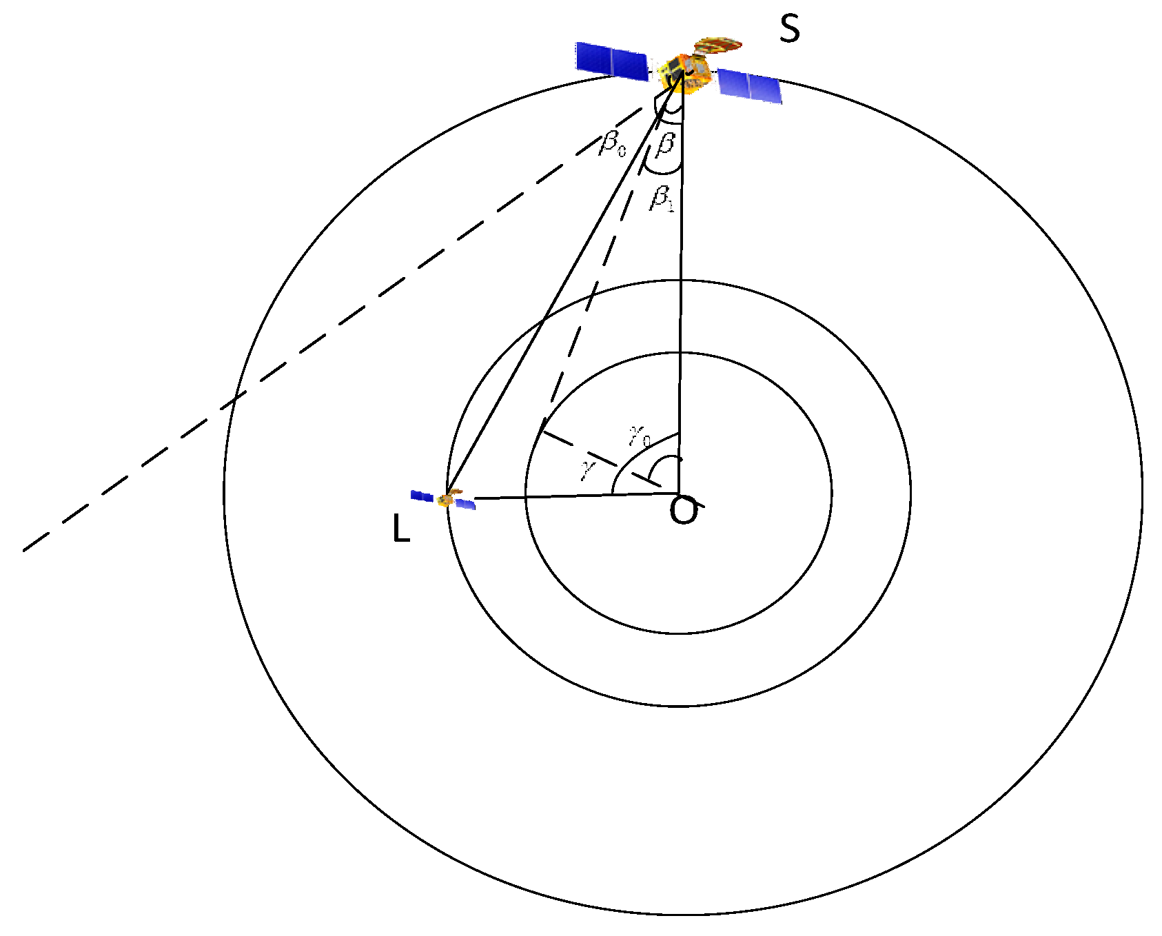
As shown in Figure 4, when angle γ is more than angle γ 0 , the satellite-based observation link is valid if β is less than angle β 0 and more than angle β 1 which is the angle between the horizontal sight point-to-satellite line and R O S .
Secondly, the position of long-term trajectory for MEO satellites can be covered with grid points of spherical space in orbital altitude. Multiple numbers of coverage for LEO satellites to all navigation satellites can be maximally evaluated by numbers of coverage for LEO satellites to the grids. Considering that the LEO satellite is in a state of high-speed motion, multiple numbers are also dynamic. The minimum and average values in the time series can be used as evaluation indicators. The calculation formulas are as follows:
C min = i = 1 N k i ( t ) min N × 100 % C a v g = i = 1 N k i ( t ) a v g N × 100 %
where C min and C a v g are respectively the minimum and average multiple number for LEO satellites to all points, k i ( t ) min and k i ( t ) a v g are respectively the minimum and average and average multiple number of coverage for LEO satellites to point i at time t , and N represents the whole number of grids in spherical space.
Finally, a minimum satellite-based observation unit can be established based on demand of coverage. That means, if C min of a LEO constellation is more than (M is the demanded natural number), the minimum combination of LEO satellites in a constellation that can meet C min equals M is the minimum satellite-based observation unit.
(2)
Orbit determination observation unit
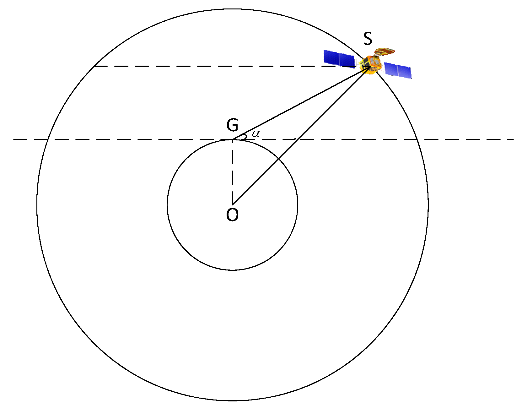
The orbit determination observation unit consists of chosen satellite-to-ground and/or satellite-based observation links that can make fast calculations of satellite orbit. Firstly, the effectiveness of observation links should be evaluated. As shown in Figure 5, angle α could be described as follows:
α = acrcos R O G 2 + R G S 2 R O S 2 2 R O G R G S 90
where R O S is the distance between the target satellite and the geocenter, R O G is the distance between the ground monitoring receiver and the geocenter, and R G S is the distance between the target satellite and ground monitoring receiver.
When angle α is less than angle α max and more than angle α min , the satellite-to-ground observation link is valid. Angle α min and angle α max are related to the performance of monitoring receiver.
Secondly, the valid number of satellite-to-ground and satellite-based observation links is respectively recorded as n and m . Then, k observation links can be selected from all valid links. There are C m + n k options as shown below:
C m + n k = ( m + n ) ! k ! × ( m + n k ) !
Thirdly, satellite position dilution of precision (SPDOP) under different combined observation links should be evaluated. SPDOP reflects geometric conditions of different observation links for the target satellite. The calculation method is described as follows:
A k × 3 j = ρ 1 x 1 ρ 1 y 1 ρ 1 z 1 ρ 2 x 1   ρ 2 y 1   ρ 2 z 1 ρ k x 1   ρ k y 1   ρ k z 1
Q j = ( A j T P A j ) 1 = q 11 q 12 q 13 q 21 q 22 q 23 q 31 q 32 q 33
S P D O P j = q 11 + q 22 + q 33 ( j = 1 , 2 C m + n k )
where A k × 3 j is the observation matrix, ρ is the range of data between the target satellite and monitoring receiver, ( x 1 , y 1 , z 1 ) is the coordinate of the target satellite, P is the weight matrix, Q is the cofactor matrix, and q is the element of matrix Q .
Finally, k observation links can be chosen according to the values of SPDOP. The S P D O P j   ( j = 1 , 2 C m + n k ) are sorted in the order from smallest to largest. The observation links related to the minimum SPDOP are the orbit determination links.

3.4. Monitoring Processing

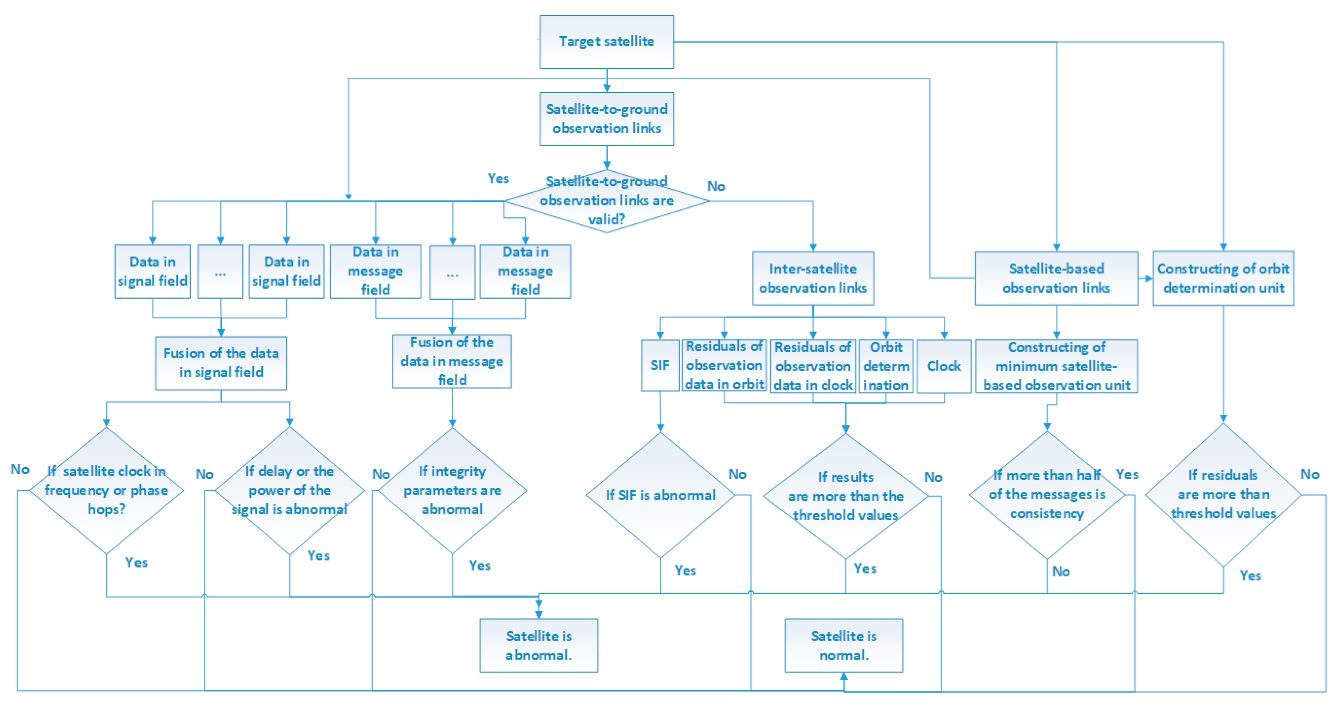
The proposed integrity monitoring system can conduct multi-dimensional monitoring according to the observation conditions of the target satellite. The monitoring processing is shown in Figure 6.
(1)
Collecting observation data of the target satellite through satellite-to-ground, inter-satellite, and satellite-based observation links.
(2)
Constructing a minimum satellite-based observation unit whose C min is no less than M. The main control station gains the returned navigation messages through the minimum satellite-based observation unit. If more than half of returned navigation messages are inconsistent, the target satellite may be abnormal.
(3)
Constructing the orbit determination unit whose SPDOP is minimum and determining the orbit of the target satellite with the chosen observation links. If residuals of orbit determination exceed the threshold, the target satellite may be abnormal.
(4)
Estimating the integrity of the target satellite according to valid observation links.
(1)
When valid satellite-to-ground observation links are more than one, data in the signal field and message field should be synchronously collected by satellite-to-ground and satellite-based observation links. The data in the signal field mainly contains the state of the satellite clock, hopping indicators of frequency and phase in signal, and signal delay. Data in the message field mainly contain the messages mentioned in Table 1. Through fusion processing of multi-source observation data, the main control station can evaluate whether there are any anomalies in the target satellite and generate related integrity messages.
(2)
When there are no valid satellite-to-ground observation links, inter-satellite ranging data and autonomous navigation messages should be gained through inter-satellite links. The state of the target satellite can be judged by five kinds of information: SIF, residuals of observation data in orbit, residuals of observation in a clock, the difference value of orbit determination errors ( U R E Orb _ t i U R E Orb _ t i 1 ), and the difference value of absolute clock errors ( Clk abs _ t i   Clk abs _ t i 1 ). If SIF, residuals of observation data, and/or difference value exceed the limitation, the target satellite may be abnormal.
Residuals can be calculated using inter-satellite ranging data. Considering the time division bidirectional measurement system of inter-satellite links, two-way ranging data should be normalized at the same time. The observation data can be described as follows.
ρ B A T 0 = ρ B A T 1 + Δ ρ B A = r A T 0 r B T 0 + c c l k A ( T 0 ) c l k B ( T 0 ) + c ( τ A R c v + τ B S e n d ) + Δ δ B A + ε
ρ A B T 0 = ρ A B T 2 + Δ ρ A B = r A T 0 r B T 0 + c c l k B ( T 0 ) c l k A ( T 0 ) + c ( τ B R c v + τ A S e n d ) + Δ δ A B + ε
where ρ B A and ρ B A represent ranging data, subscripts A and B represent satellite A and satellite B , r represents the three-dimensional position vector, c l k is the clock error, τ S e n d and τ R c v represent respectively the sending delay and receiving delay, c is the speed of light, ε represents noise and other unmodeled errors, and Δ δ represents modeled errors such as the phase center correction of the satellite antenna and correction of the relativistic effect.
By summing and differentiating the two-way ranging data, orbit and clock parameters can be decoupled. Residuals of observation data in orbit can be gained using Formula (8) plus Formula (9). Similarly, residuals of observation data in the clock can be gained using Formula (8) minus Formula (9).
r A T 0 r B T 0 = ρ B A T 0 + ρ A B T 0 2 + Δ δ B A + Δ δ A B 2 + c τ A R c v + τ B S e n d + τ B R c v + τ A S e n d 2
c l k A ( T 0 ) c l k B ( T 0 ) = ρ B A T 0 ρ A B T 0 2 c + Δ δ A B Δ δ B A 2 c + τ A S e n d τ A R c v 2 τ B S e n d τ B R c v 2
Orbit determination errors are the differences between autonomous ephemeris and forecasted precision of the target satellite. Then, the three-dimensional error of orbit determination can be described as follows:
U R E Orb _ t i   =   0.96 Δ R 2 + 0.04 Δ T 2 + Δ N 2
where U R E Orb _ t i represents the three-dimensional error of orbit determination at time t i and Δ R , Δ T , and Δ N represent the orbit error in radial, tangential, and normal directions, respectively.
Clock errors are the differences between clock parameters of autonomous messages and the main control station to evaluate whether the satellite’s clock is abnormal.

3.5. Augmentation Parameters of Integrity with Multi-Source Observation Links

LEO satellites as satellite-based monitoring stations can not only improve wide-area monitoring capability for navigation satellites but also be added to the resolution of navigation messages. Various research works on LEO orbit determination were carried out for the CHAMP satellite, GRACE satellite, Jason satellite, and other LEO satellites [9,10,11,12], verifying that orbit accuracy of LEO satellites could reach centimeter level and LEO satellites could further augment the orbit accuracy of navigation satellite [17]. This paper proposes that the augmentation parameters of integrity should be solved with multi-source observation links to verify the effect of LEO satellites in indicating the accuracy of integrity.
(1)
Augmentation parameter of orbit correction
Based on the precise point positioning model, orbit errors can be gained with kinematics equations and observation equations of navigation satellites and LEO satellites. Then, orbit errors could be smoothed with phase data to gain augmentation parameters of orbit correction.
(2)
Augmentation parameter of clock correction
Based on pseudo-ranging and phase data of the observation equation, the augmentation parameter of clock correction could be gained as the coordinates of satellites and stations are fixed, and the clock of the main control station is chosen as the reference clock.
(3)
User differential ranging error
User differential ranging error (UDRE) is the confidence limit value of the pseudo-range error, which is corrected by the augmentation parameters of orbit correction and clock correction and other errors, such as relativistic effect, tropospheric delay, antenna phase center bias, Earth tide, and multipath effect errors.

4. Analysis of Optimization Strategies

4.1. Coverage Analysis of Satellite-Based Observation Unit

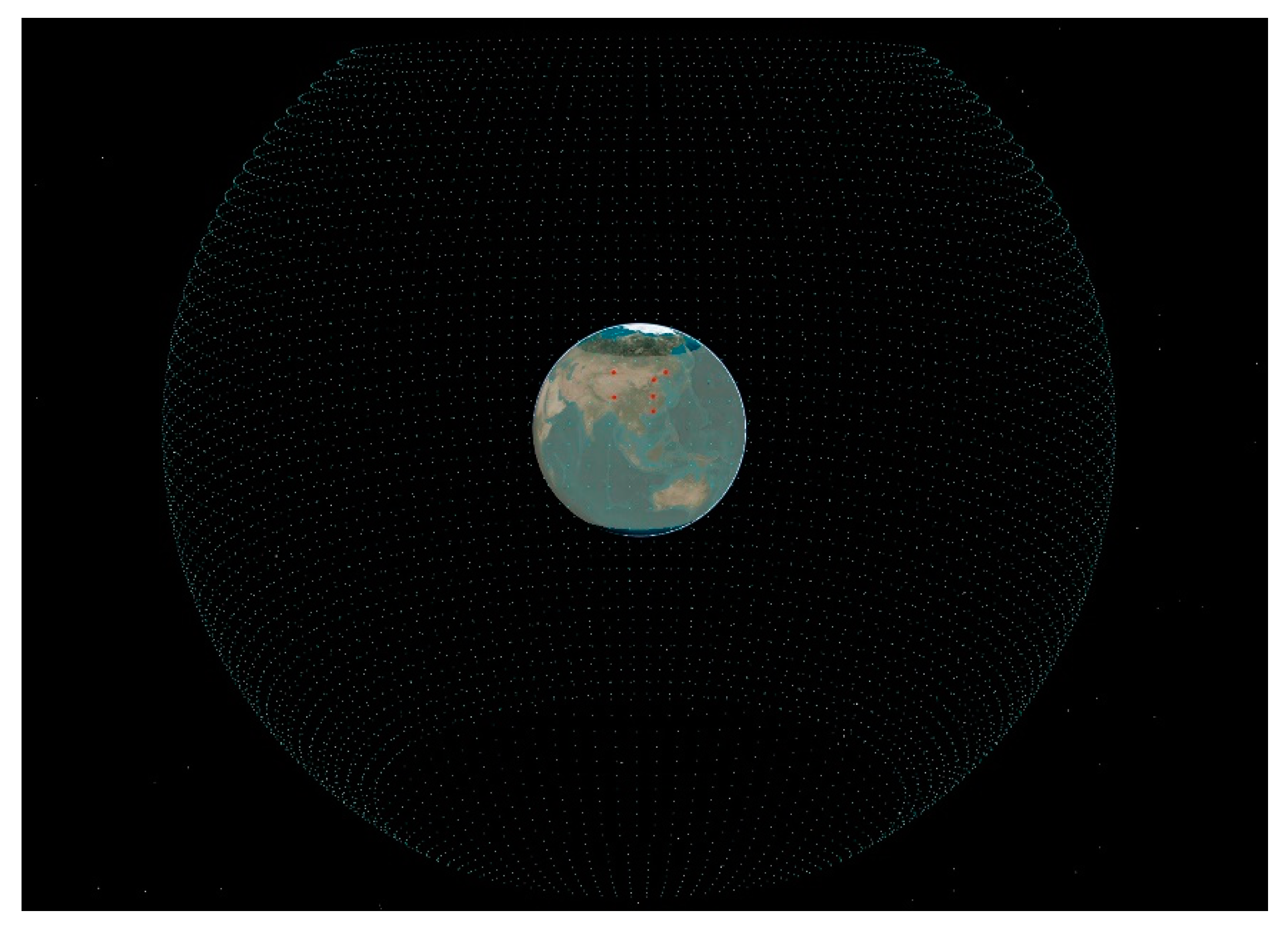
Based on the orbit inclination and altitude of BDS-3 MEO satellites, the spatial region surrounding the Earth could be divided into 8242 grid points by 2° × 2° intervals. With six IGS stations (BJFS, CHAN, HKSL, LHAZ, URUM, and WUH2) in China chosen as ground monitoring stations, the basic scenario is shown in Figure 7. Moreover, LEO satellites with an orbit height of 1000 km and an inclination of 55° could effectively observe the grid points. The observation elevation angle of receivers for the grids is set to be 10°.
Through coverage analyses with the support of different LEO satellites to grid points, the observation performance of LEO satellites to navigation satellites could be approximately obtained. Supposing the satellite-based observation unit has 6, 12, 30, or 60 satellites, the designed scenarios and test results are shown in Table 2.
As shown in Table 2, the following can be seen:
(1)
C a v g is 3.47, 5.17, 10.36, and 18.75 in scenarios 2 to 5, respectively, which have nearly 1 time, 2 times, 5 times, and 10 times of improvement, respectively, compared with the results in scenario 1.
(2)
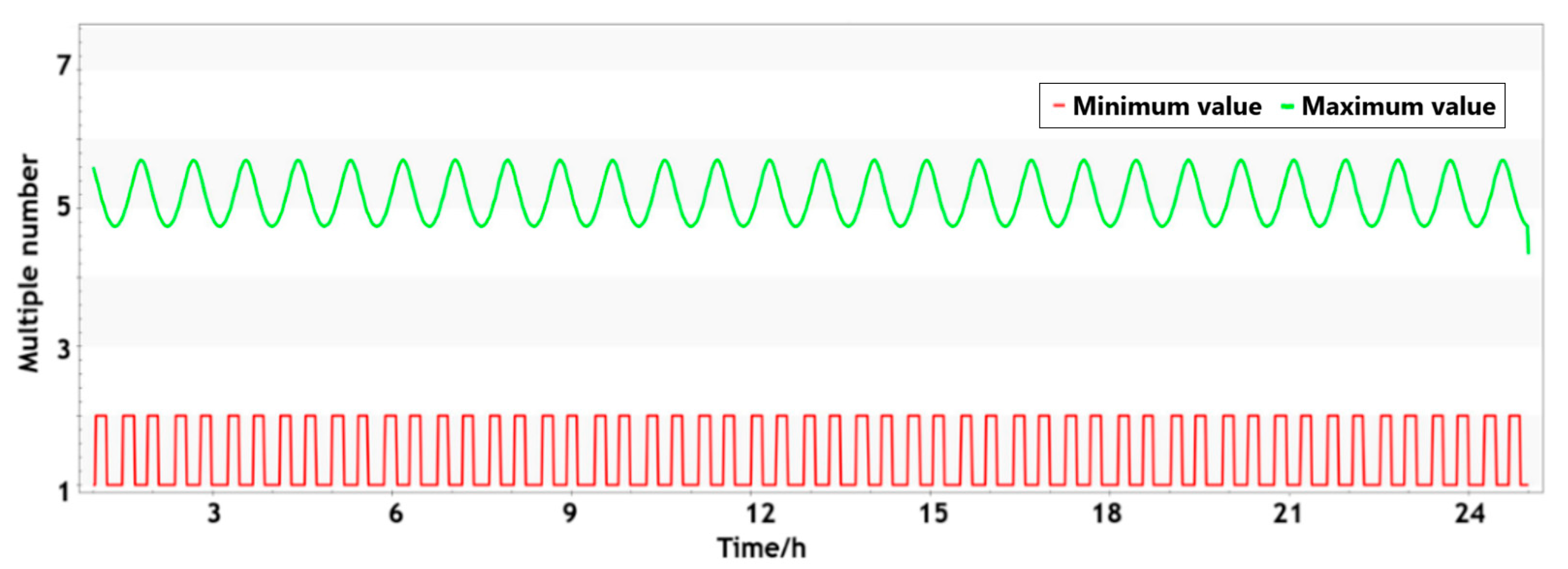
As shown in Figure 8, Figure 9 and Figure 10, the multiple number and coverage rate in scenario 3 could change with the motion of LEO satellites. The uncovered grids also change greatly.
(3)
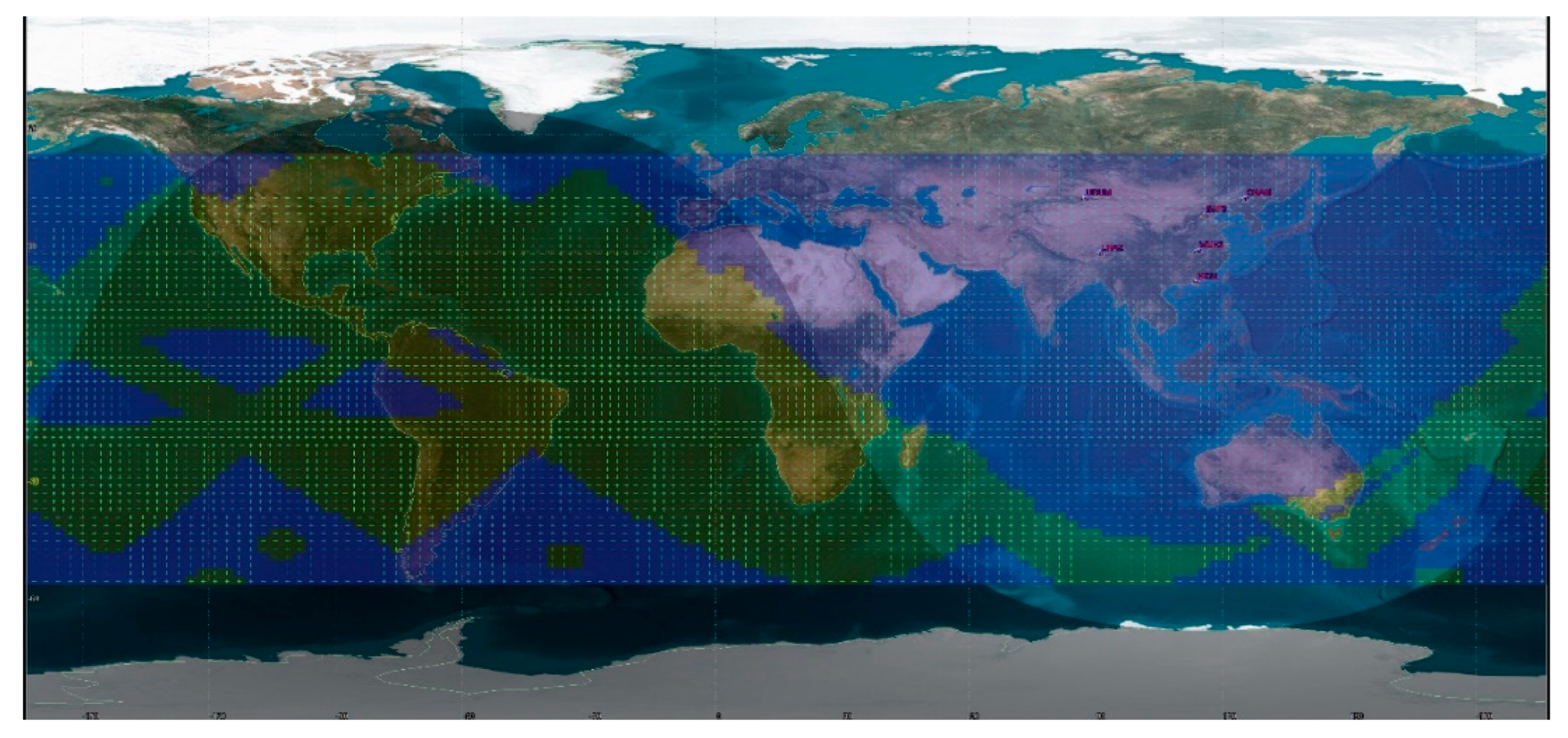
With the support of 30 LEO satellites, the coverage rate of four-multiple numbers can reach 100%. That means any grid can be simultaneously monitored by more than four LEO satellites, making it possible to calculate integrity parameters in real time.
(4)
LEO satellites can effectively make up for the shortage of ground monitoring stations and realize real-time return of navigation messages for navigation satellites. Nevertheless, an increase in LEO satellites also brings the problem of data redundancy.

4.2. SPDOP Analysis of Orbit Determination Unit

Considering that the calculation of SPDOP needs at least four observation links, more than 30 LEO satellites should be chosen to carry out the analysis of SPDOP. With the choice of six IGS stations mentioned above, the designed scenarios with support of different orbit determination units and test results are shown in Table 3.
The following can be seen from the results in Table 3:
(1)
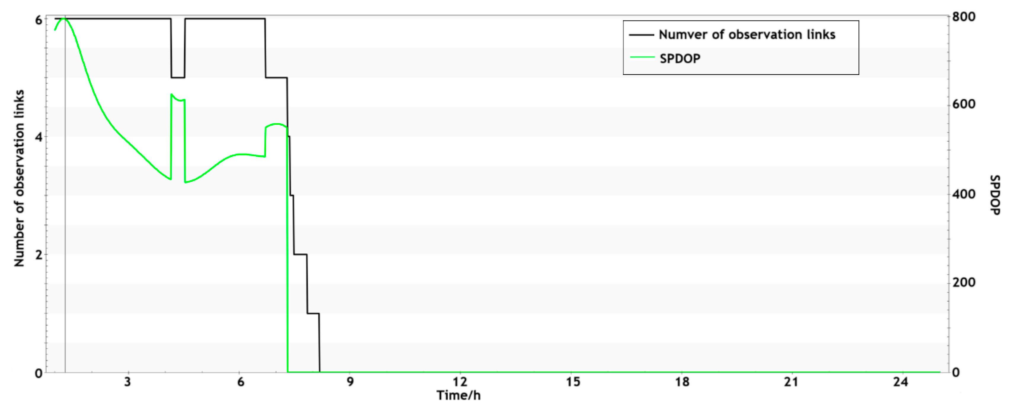
In scenario 1, the valid number of observation links is only 1.60. The minimum and average values of SPDOP are 428.02 and 545.00, respectively, which is quite large even with the support of six stations synchronously, as shown in Figure 11.
(2)
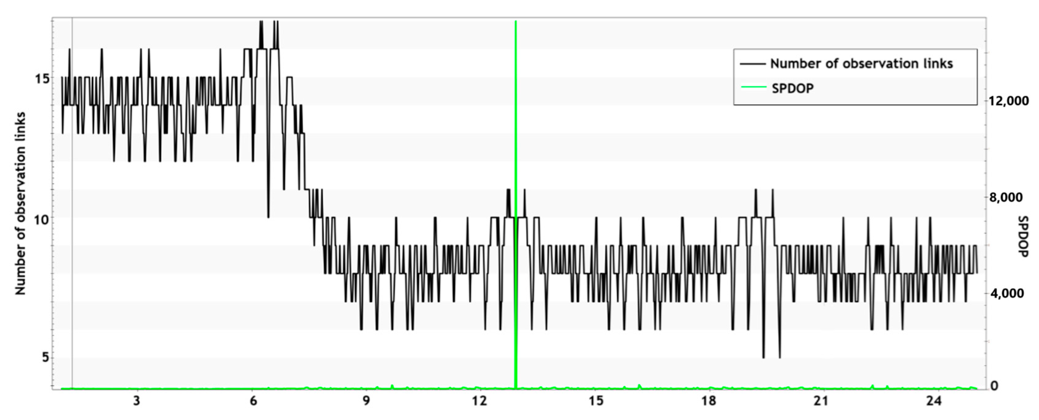
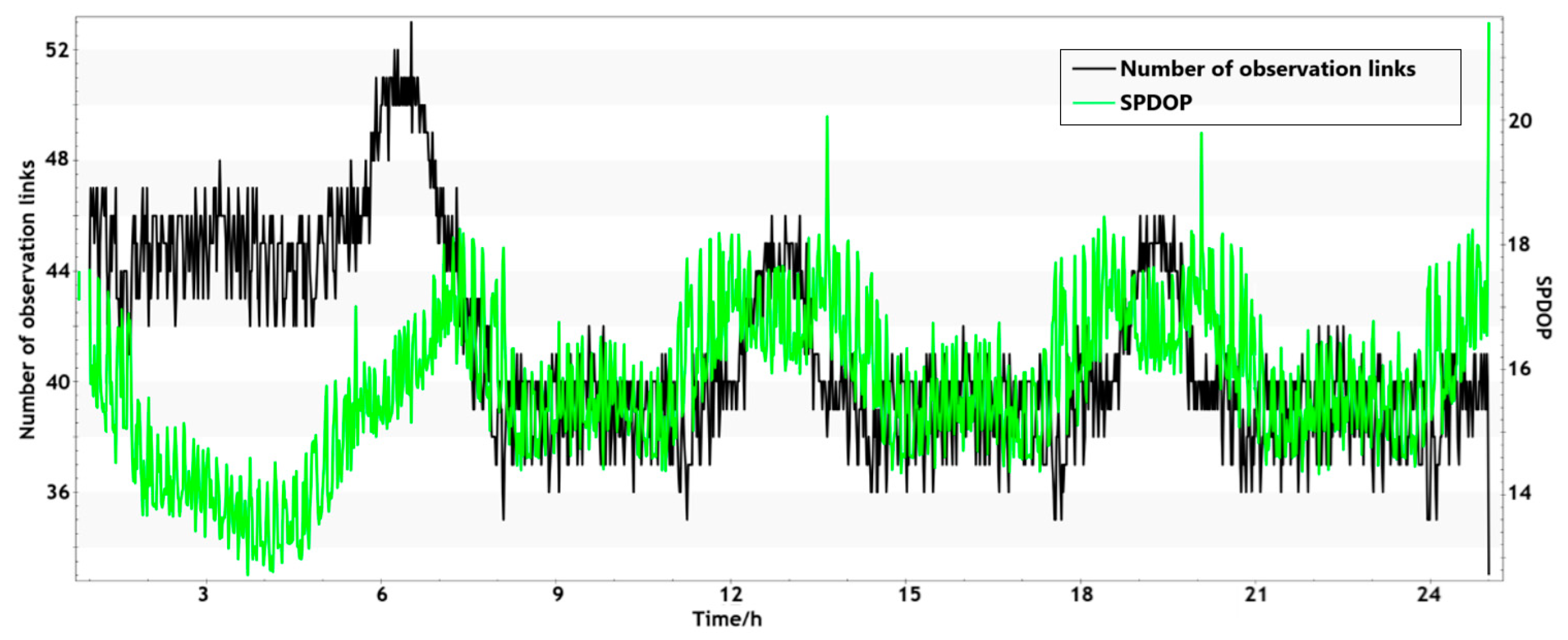
As shown in Figure 12, Figure 13 and Figure 14, the value of SPDOP is respectively 38.37, 24.60, and 15.71, which could be improved by 92.95%, 95.49%, and 97.12% compared with the results in scenario 1. The value of SPDOP in scenario 2 changes greatly when the observation links are less than five. With the increasing number of LEO satellites, the augmentation effect of LEO satellites on SPDOP will gradually weaken. It means that a small number of LEO satellites can effectively improve the observation geometry the target satellite.
(3)
The minimum duration of observation links is respectively 10,250.36 s, 91.92 s, 46.75 s, and 10.45 s. Although the addition of LEO can effectively increase the number of observation links, it cannot guarantee continuous observation, which brings about the problem of frequent switching for observation links.

4.3. Performance Analysis of Integrity Parameter

UDRE can effectively indicate service area and service accuracy, representing the service performance of the system. As to the service area, the calculation of integrity parameters related to real-time service performance is restricted by the layout of ground monitoring stations. With the support of LEO satellites, variation in the service area can be evaluated by the effective duration of integrity parameters. Regarding service accuracy, UDRE is a pseudo-distance residual of the spatial signal, which can be determined using the original observed data and theoretical distances between the monitoring receiver and the target satellite. Then, service accuracy could be estimated by the product of UDRE and the position dilution of precision (PDOP). This study constructs scenarios with the support of different LEO constellations to verify the effect on service area and accuracy, as shown in Table 4.
The following can be seen:
(1)
The effective duration of UDRE is about 8.00 h, which is only 33.31% of the length of a single day because of the limitation of ground monitoring stations. The average simulation value of UDRE is 0.427 m, which is basically the same as the real performance of BDS-3.
(2)
With the support of 6, 12, or 60 LEO satellites, the effective duration of UDRE is respectively 16.11 h, 20.93 h, and 24 h, as shown in Table 5, meaning that the single-day effective rate is 67.11%, 87.19%, and 100%, respectively. As the number of LEO satellites increases, the area where UDRE parameters can be solved in real time can be gradually expanded to the global area, verifying that LEO satellites could be used as satellite-based monitoring stations to obtain more observation data.
(3)
The average value of UDRE is respectively 0.397 m, 0.388 m, and 0.351 m in scenarios 2 to 4, which have 7%, 9%, and 18% improvement compared with the results in scenario 1, verifying that the satellite-based observation data of LEO satellites could support the solution of UDRE.
(4)
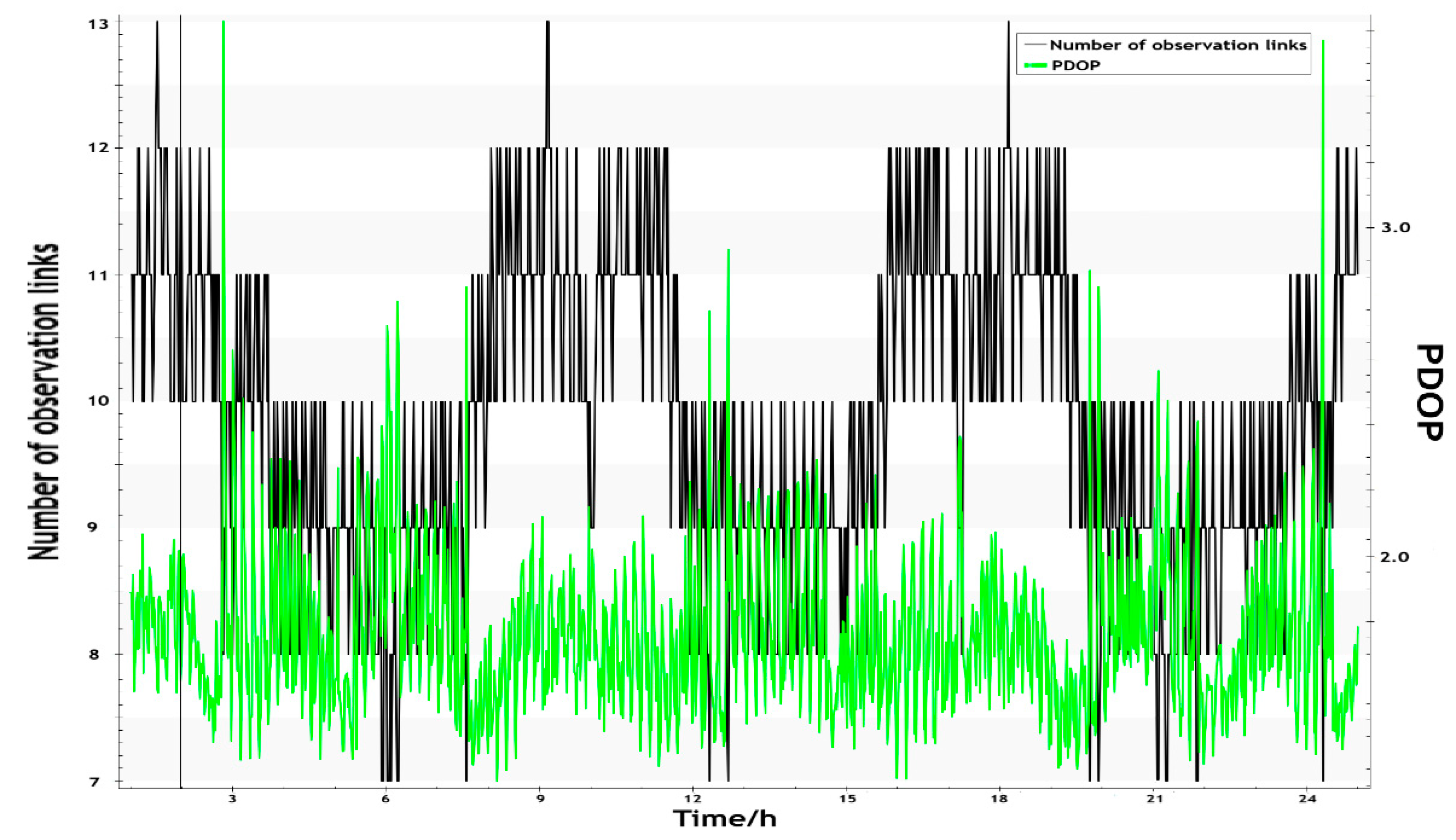
As shown in Table 6 and Figure 15, PDOP could be improved by the addition of satellite-based observation links. There is no significant difference in PDOP values among different regions, meaning that the deployment of the constellation is relatively uniform.
(5)
The service accuracy could be estimated using the product of PDOP and UDRE. As shown in Table 6, average service accuracy is respectively 0.93 m, 0.88 m, and 0.65 m in scenarios 2 to 4, which have 8.9%, 13.7%, and 36.3% improvement compared with the results in scenario 1. Although a small number of LEO satellites could not obviously improve the PDOP, the service accuracy could be effectively improved.

5. Conclusions

In the face of deployment limitations of monitoring stations and constraints on the communication capacity of inter-satellite links, this study proposes an integrity monitoring system with the support of multi-source observation links, which consist of satellite-to-ground, inter-satellite, and satellite-based observation links. Moreover, optimizing strategies are proposed to improve monitoring efficiency for navigation satellites. The main conclusions from this study are summarized as follows:
(1)
According to the observation conditions of the target satellite, the designed integrity monitoring system can conduct multi-dimensional monitoring in signal and message fields. In the signal field, the state of the satellite clock, hopping indicators of frequency and phase in signal, and signal delay should be monitored. In the message field, basic navigation messages, satellite-based augmentation messages, and autonomous messages should be considered comprehensively to evaluate the state of the target satellite. Indicator parameters, residuals of observation data, orbit determination errors, and clock errors can all indicate the state of the navigation satellite.
(2)
LEO satellites can effectively make up for the shortage of ground monitoring stations and realize real-time return of navigation messages for navigation satellites. With the support of 30 LEO satellites, the coverage rate of four-multiple numbers can reach 100%. This means that it does not matter where the target satellite is; it can be monitored by no less than four LEO satellites. A small amount of LEO satellites could realize full-arc monitoring of navigation satellites. For a large LEO constellation, it is necessary to construct a minimum observation unit for the effective return of navigation messages and to avoid data redundancy.
(3)
Realization of the orbit determination needs not only effective observation links but also reasonable observation geometry conditions. As the number of LEO satellites increases, the augmentation effect of LEO satellites to SPDOP would gradually weaken. The complexity of orbit determination would increase as more parameters are added to the normal equation of orbit errors, and more systematic errors would be brought in. Under the guarantee of effective observation links, it is an effective way to construct an orbit determination unit to optimize observation links and reduce equation dimension for fast calculation of satellite orbit.
(4)
LEO satellites can not only improve wide-area monitoring capability for navigation satellites but also augment the resolution accuracy of navigation messages. As the number of LEO satellites increases, the area where integrity parameters can be solved in real time is constantly expanding to a global area. With the support of 6, 12, or 60 LEO satellites, average service accuracy is respectively 0.93 m, 0.88 m, and 0.65 m, which has 8.9%, 13.7%, and 36.3% improvement compared with the result of regional service, verifying that LEO satellites have practical application values for augmentation of BDS-3 integrity monitoring.

Author Contributions

Conceptualization, formal analysis, investigation, data curation, and writing—original draft preparation, J.X. and D.W.; software and validation, K.L. All authors have read and agreed to the published version of the manuscript.

Funding

This research was funded by the National Natural Science Foundation of China (grant nos. 12103077).

Data Availability Statement

Beijing Satellite Navigation Center provides all the test data used in this contribution. All data will be made available for scientific research purposes by request to the Beijing Satellite Navigation Centre.

Conflicts of Interest

The authors declare no conflicts of interest.

References

  1. Cen, J.; Wang, M.; Qian, S. Analysis of modernization GNSS navigation message’s designing. J. Electron. Inf. Technol. 2011, 33, 211–216. [Google Scholar]
  2. Fan, M.; Zhou, J.; Niu, F.; Chang, Z. Analysis for satellite navigation system basic integrity algorithm and performance. J. Geomat. Sci. Technol. 2011, 28, 407–415. [Google Scholar]
  3. Li, Z.; Hao, J.; Li, J. Navigation message designing in Galileo OS SIS ICD. J. Geomat. Sci. Technol. 2011, 28, 14–18. [Google Scholar]
  4. China Satellite Navigation System Administration Office (CSNO). BeiDou Navigation Satellite System Signal in Space Interface Control Document: Open Service Signals B2a [EB/OL]. 23 February 2020. Available online: http://www.beidou.gov.cn/zt/xwfbh/wznfbh/gdxw3/201712/W020171226733918059992.pdf (accessed on 26 July 2024).
  5. China Satellite Navigation System Administration Office (CSNO). BeiDou Navigation Satellite System Signal In Space Interface Control Document: Open Service Signals B1C [EB/OL]. 23 February 2020. Available online: http://www.beidou.gov.cn/yw/xwzx/201712/W020171226734109267772.pdf (accessed on 26 July 2024).
  6. China Satellite Navigation System Administration Office (CSNO). BeiDou Navigation Satellite System Signal in Space Interface Control Document: Open Service Signals B3I [EB/OL]. 23 February 2020. Available online: http://www.beidou.gov.cn/xt/gfxz/201802/P020180209623601401189.pdf (accessed on 26 July 2024).
  7. Zhang, X.; Wu, M.; Liu, W.; Li, X.; Yu, S.; Lu, C.; Wickert, J. Initial assessment of the COMPASS/BeiDou-3: New-generation navigation signals. J. Geod. 2017, 91, 1225–1240. [Google Scholar] [CrossRef]
  8. Yang, Y. Concepts of comprehensive PNT and related key technologies. Acta Geod. Cartogr. Sin. 2016, 45, 505–510. [Google Scholar]
  9. Haines, B.; Bar-Sever, Y.; Bertiger, W.; Desai, S.; Willis, P. One-centimeter orbit determination for Jason-1: New GPS-based strategies. Mar. Geod. 2004, 27, 299–318. [Google Scholar] [CrossRef]
  10. Bock, H.; Jäggi, A.; Meyer, U.; Visser, P.; van den IJssel, J.; van Helleputte, T.; Heinze, M.; Hugentobler, U. GPS-derived orbits for the GOCE satellite. J. Geod. 2010, 85, 807–818. [Google Scholar] [CrossRef]
  11. Kang, Z.; Tapley, B.; Bettadpur, S.; Rim, H.; Nagel, P. Precise orbit determination for CHAMP using accelerometer data. Adv Astronaut. Sci. 2012, 112, 1405–1410. [Google Scholar]
  12. Xu, G.; Xu, J. On the singularity problem in orbital mechanics. Mon. Not. R. Astron. Soc. 2013, 429, 1139–1148. [Google Scholar] [CrossRef]
  13. Li, X.; Hu, X.; Guo, R.; Tang, C.; Liu, S.; Xin, J.; Guo, J.; Tian, Y.; Yang, Y.; Yang, J.; et al. Precise orbit determination for BDS-3 GEO satellites enhanced by intersatellite links. GPS Solut. 2022, 27, 8. [Google Scholar] [CrossRef]
  14. Yang, Y.; Yang, Y.; Hu, X.; Chen, J.; Guo, R.; Tang, C.; Zhou, S.; Zhao, L.; Xu, J. Inter-satellite link enhanced orbit determination for BeiDou-3. J. Navig. 2020, 73, 115–130. [Google Scholar] [CrossRef]
  15. Zhou, W.; Gao, W.; Lin, X.; Hu, X.; Ren, Q.; Tang, C. Emerging errors in the orientation of the constellation in GNSS autonomous orbit determination based on inter-satellite link measurement. Adv. Space Res. 2022, 70, 3156–3172. [Google Scholar] [CrossRef]
  16. Feng, L.; Mao, Y.; Song, X.; Sun, B. Analysis of the accuracy of Beidou combined orbit determination enhanced by LEO and ISL. Acta Geod. Et Cartogr. Sinica 2016, 45, 109–115. [Google Scholar]
  17. Shen, D.; Meng, Y.; Bian, L.; Lei, W.; Wang, Y.; Yan, T.; Xie, J. A global navigation augmentation system based on LEO communication constellation. J. Terahertz Sci. Electron. Inf. Technol. 2019, 17, 209–2014. [Google Scholar]
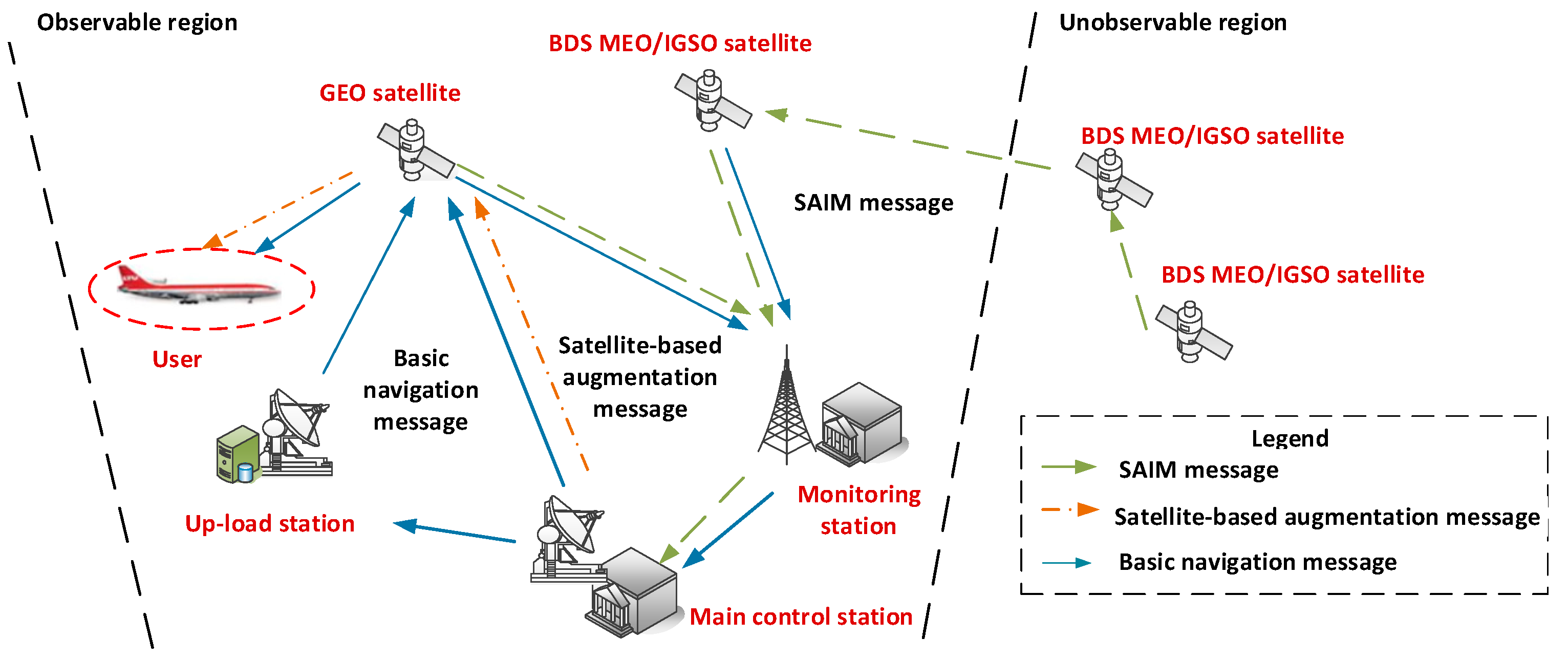
Figure 1. Design of integrity monitoring system for the BDS-3 satellite.
Remotesensing 16 04574 g001
Figure 2. Design of integrity monitoring system with support of multi-source observation links.
Remotesensing 16 04574 g002
Figure 3. The chosen valid satellite-based observation links ( γ γ 0 ).
Remotesensing 16 04574 g003
Figure 4. The chosen valid satellite-based observation links ( γ > γ 0 ).
Remotesensing 16 04574 g004
Figure 5. The chosen valid satellite-to-ground observation links.
Remotesensing 16 04574 g005
Figure 6. Processing of integrity monitoring system.
Remotesensing 16 04574 g006
Figure 7. Divided grid points and chosen ground monitoring stations.
Remotesensing 16 04574 g007
Figure 8. Multiple numbers in scenario 3.
Remotesensing 16 04574 g008
Figure 9. Coverage rate of four-multiple numbers in scenario 3.
Remotesensing 16 04574 g009
Figure 10. Coverage rate of more than four-multiple numbers in scenario 3. (The grids in the blue area can be monitored by no less than four LEO satellites; the grids in the yellow area can be monitored by less than four LEO satellites).
Remotesensing 16 04574 g010
Figure 11. Number of available links and SPDOP values in scenario 1.
Remotesensing 16 04574 g011
Figure 12. Number of available links and SPDOP values in scenario 2.
Remotesensing 16 04574 g012
Figure 13. Number of available links and SPDOP values in scenario 3.
Remotesensing 16 04574 g013
Figure 14. Number of available links and SPDOP values in scenario 4.
Remotesensing 16 04574 g014
Figure 15. Number of available links and PDOP values of BJFS in scenario 4.
Remotesensing 16 04574 g015
Table 1. Update cycles and broadcast strategies of integrity parameters.
TypeIntegrity ParameterMessage TypeSignalUpdate CycleData SourceService Object
Basic integrity parametersSatH1D1B1I/B3I30 sMain
control station
Global
user
D23 s
HSB-CNAV1B1C18 sMain
control station/
satellite
B-CNAV2B2a3 s
HeaD1B1I/B3I30 sMain
control station
D23 s
HealthB-CNAV1B1C18 s
B-CNAV2B2a3 s
RURAD2B1I/B3I18 s
SISMAI/SISAI/
DIF, SIF, AIF
B-CNAV1B1C30s/360s/changing timeMain
control station/
satellite
B-CNAV2B2a
Augmentation integrity parametersUDREID2B1I/B3I3 sMain
control station
Regional
user
B-CINAVBDSBAS-B1C6 s
GIVEID2B1I/B3I180 s/360 s
B-CINAVBDSBAS-B1C240 s
DFREIB-CINAVBDSBAS-B2a6s/alarm time
DFRECIB-CINAVBDSBAS-B2a6s/alarm time
Table 2. Designed scenarios of satellite-based observation units and test results.
ScenarioMonitoring PointsMultiple NumberCoverage Rate of M-Multiple Number
≥1≥4
C min C a v g MinAveMinAve
1Six ground monitoring stations01.77041.37027.96
2Six ground monitoring stations + six LEO satellites (Walker 60/6/1, each orbital plane chooses one satellite)03.4768.2687.5033.2637.10
3Six ground monitoring stations + 12 LEO satellites (Walker 60/6/1, each orbital plane chooses two satellites)15.1710010044.4668.98
4Six ground monitoring stations + 30 LEO satellites (Walker30/6/1)410.36100100100100
5Six ground monitoring stations + 60 LEO satellites (Walker60/6/1)1118.75100100100100
Table 3. Designed scenarios of orbit determination units and test results.
ScenarioMonitoring PointsSPDOPNumber of Observation LinksDuration of Observation Links
MinAveMinAveMinAve
1Six ground monitoring stations428.02545.0001.6010,250.3619,800.80
2Six ground monitoring stations +
30 LEO satellite (Walker30/6/1)
21.0938.3749.9491.922000.98
3Six ground monitoring stations +
60 LEO satellite (Walker60/6/1)
17.1424.601218.2646.751849.72
4Six ground monitoring stations +
144 LEO satellite (Walker144/12/1)
13.0415.713341.2910.451878.55 s
Table 4. Designed scenarios of UDRE duration.
ScenarioMonitoring Points
1Six ground monitoring stations
2Six ground monitoring stations + 6 LEO satellite (Walker 60/6/1, each orbital plane chooses one satellite)
3Six ground monitoring stations + 12 LEO satellite (Walker 60/6/1, each orbital plane chooses two satellites)
4Six ground monitoring stations + 60 LEO satellite (Walker 60/6/1)
Table 5. Duration of UDRE in different scenarios.
PRNScenario 1Scenario 2Scenario 3Scenario 4
Duration
(h)
RateUDRE
(m)
Duration
(h)
RateUDRE
(m)
Duration
(h)
RateUDRE
(m)
Duration
(h)
RateUDRE
(m)
C198.0933.71%0.47613.4456.00%0.43521.5489.75%0.34724100%0.355
C207.4731.13%0.47414.7661.50%0.35919.8682.75%0.45424100%0.288
C215.9024.58%0.41113.5656.50%0.42318.9378.88%0.36424100%0.336
C227.0829.50%0.45816.1767.38%0.42022.1692.33%0.34024100%0.310
C238.1433.92%0.37215.7665.67%0.34120.8386.79%0.34924100%0.403
C248.5135.46%0.46716.8970.38%0.33419.7482.25%0.40524100%0.332
C259.7640.67%0.34718.6477.67%0.39521.6890.33%0.38324100%0.364
C267.5431.42%0.39015.8766.13%0.46820.1684.00%0.36424100%0.311
C278.0933.71%0.34914.9962.46%0.37019.7882.42%0.43824100%0.375
C288.1634.00%0.35815.6765.29%0.40821.0787.79%0.40024100%0.325
C297.9833.25%0.48815.9166.29%0.35119.4981.21%0.39524100%0.382
C3010.0341.79%0.46518.7678.17%0.43522.8395.13%0.45224100%0.387
C327.6832.00%0.39815.3864.08%0.35620.4785.29%0.35424100%0.396
C337.0929.54%0.51116.1667.33%0.39621.6490.17%0.42724100%0.352
C348.6335.96%0.34717.4872.83%0.42722.0992.04%0.42624100%0.298
C357.6531.88%0.41915.7365.54%0.45720.9587.29%0.36924100%0.320
C366.0925.38%0.40914.1558.96%0.46819.7282.17%0.39824100%0.420
C377.9833.25%0.47815.8866.17%0.40222.3993.29%0.32124100%0.309
C416.5927.46%0.48314.0758.63%0.33820.9687.33%0.31824100%0.408
C427.6932.04%0.37416.8570.21%0.33921.3388.88%0.39224100%0.365
C4310.3443.08%0.42818.8378.46%0.35620.6986.21%0.43024100%0.433
C449.5739.88%0.42118.6377.63%0.44922.0591.88%0.45424100%0.298
C458.1934.13%0.45617.4872.83%0.35621.9391.38%0.33024100%0.351
C467.6431.83%0.46815.4764.46%0.44519.9182.96%0.39824100%0.302
Average8.0033.31%0.42716.1167.11%0.39720.9387.19%0.38824100%0.351
Table 6. Service accuracy and PDOP.
ScenarioBJFSCHANHKSLLHAZURUMWUH2Average
PDOPService Accuracy (m)PDOPService Accuracy (m)PDOPService Accuracy (m)PDOPService Accuracy (m)PDOPService Accuracy (m)PDOPService Accuracy (m)PDOPService Accuracy (m)
12.320.992.361.012.361.012.391.022.411.032.401.022.371.02
22.260.902.290.912.310.922.320.922.340.932.330.932.310.93
32.190.852.220.862.270.882.260.882.200.852.280.882.240.88
41.760.621.770.621.960.691.860.651.770.621.860.651.830.65
Disclaimer/Publisher’s Note: The statements, opinions and data contained in all publications are solely those of the individual author(s) and contributor(s) and not of MDPI and/or the editor(s). MDPI and/or the editor(s) disclaim responsibility for any injury to people or property resulting from any ideas, methods, instructions or products referred to in the content.