Article

Modeling of Solar Radiation Pressure for BDS-3 MEO Satellites with Inter-Satellite Link Measurements

1
School of Remote Sensing and Geomatics Engineering, Nanjing University of Information Science and Technology, No. 219 NingLiu Road, Nanjing 210044, China
2
Technology Innovation Center for Integration Applications in Remote Sensing and Navigation, Ministry of Natural Resources, No. 219 NingLiu Road, Nanjing 210044, China
3
Jiangsu Engineering Center for Collaborative Navigation/Positioning and Smart Application, No. 219 NingLiu Road, Nanjing 210044, China
4
Surveying and Mapping Institute Lands and Resource Department of Guangdong Province, Guangzhou 510663, China
5
GNSS Research Center, Wuhan University, No. 129 Luoyu Road, Wuhan 430079, China
*
Author to whom correspondence should be addressed.
Remote Sens. 2024, 16(20), 3900; https://doi.org/10.3390/rs16203900
Submission received: 6 September 2024 / Revised: 14 October 2024 / Accepted: 17 October 2024 / Published: 20 October 2024
(This article belongs to the Special Issue GNSS Positioning and Navigation in Remote Sensing Applications)

Abstract

:
As the largest non-gravitational force, solar radiation pressure (SRP) causes significant errors in precise orbit determination (POD) of the BeiDou global navigation satellite system (BDS-3) medium Earth orbit (MEO) satellite. This is mainly due to the imperfect modeling of the satellite’s cuboid body. Since the BDS-3’s inter-satellite link (ISL) can enhance the orbit estimation of BDS-3 satellites, the aim of this study is to establish an a priori SRP model for the satellite body using 281-day ISL observations to reduce the systematic errors in the final orbits. The adjustable box wind (ABW) model is employed to refine the optical parameters for the satellite buses. The self-shadow effect caused by the search and rescue (SAR) antenna is considered. Satellite laser ranging (SLR), day-boundary discontinuity (DBD), and overlapping Allan deviation (OADEV) are utilized as indicators to assess the performance of the a priori model. With the a priori model developed by both ISL and ground observation, the slopes of SLR residual for the China Academy of Space Technology (CAST) and Shanghai Engineering Center for Microsatellites (SECM) satellites decrease from −0.097 cm/deg and 0.067 cm/deg to −0.004 cm/deg and −0.009 cm/deg, respectively. The standard deviation decreased by 21.8% and 26.6%, respectively. There are slight enhancements in the average values of DBD and OADEV, and a reduced β-dependent variation is observed in the OADEV of the corresponding clock offset. We also found that considering the SAR antenna only slightly improves the orbit accuracy. These results demonstrate that an a priori model established for the BDS-3 MEO satellite body can reduce the systematic errors in orbits, and the parameters estimated using both ISL and ground observation are superior to those estimated using only ground observation.

1. Introduction

From 2017 to 2020, 24 medium Earth orbit (MEO) satellites, 3 inclined geosynchronous orbit (IGSO) satellites, and 3 geostationary Earth orbit (GEO) satellites were launched into space [1,2]. These satellites constructed the BeiDou global navigation satellite system (BDS-3). Subsequently, GEO-4 (C62) was launched on 17 May 2023, followed by MEO-26 (C48) and MEO-28 (C50) on 26 December 2023, to improve system reliability. BDS-3 satellites are grouped into two types, which are produced by the China Academy of Space Technology (CAST) and Shanghai Engineering Center for Microsatellites (SECM) of the Chinese Academy of Science [3], respectively. The expansion of the services provided by the BDS-3 from regional to global relies on the Ka-band inter-satellite link (ISL) payloads carried. Different from the BeiDou regional navigation satellite system (BDS-2), BDS-3 has the ability to inter-satellite range and real-time update the navigation message via its ISLs [4,5], so that it can provide global standard point positioning (SPP) service with an accuracy of 10 m [1].
For high-precision positioning users, however, ISL observations are not available, and thus it is not practically used for the enhancement of post precise orbit and clock offset estimation. Currently, a total of five analysis centers (ACs) routinely provide the precise orbit and clock products for the BDS-3 satellite [6,7], but none of them are estimated with ISL observations in the product generation. The orbit accuracy of the MEO satellites as evaluated by SLR residuals is on the level of 4–9 cm [6]. The analysis of SLR residuals and the stability of clock offsets demonstrated that the main error that comes from precise orbit determination (POD) with respect to the β angle is derived from the imperfect SRP modeling. The deficiencies in the SPR model led to a degraded orbit and thus reduced the clock quality. Therefore, refinement of the SRP model is a prerequisite for further improvement of the orbiting accuracy and clock difference accuracy.
SRP is a kind of non-conservative force that occurs when satellites are exposed to sunlight as they fly in space. The SRP acceleration of the BDS-3 MEO satellite is in the range of about 60–150 nm/s2 [8], which affects the daily orbit determination by several hundred meters. However, the geometric structure and optical parameters of the satellite surface cannot be accurately obtained, and the operating attitude is generally difficult to accurately describe. Satellites may enter the shadowed areas of Earth. As a result, it is difficult to model such effects on satellites.
SRP modeling of GNSS satellites usually employs either an analytical model or a semi-analytical model. The analytical model can calculate the SRP acceleration according to the surface dimensions and optical properties, such as specular and diffuse reflection coefficients, providing a clear physical interpretation. Typical models are the ROCK series models and box wing models [9,10,11,12,13]. However, these models’ accuracy is limited by incomplete disclosure of satellite properties and the omission of material aging effects. In other words, the analytical model is unable to utilize real observation to adjust the optical properties. In contrast, the advantage of the semi-analytical model lies in its ability to utilize the measurement to adjust a priori optical parameters of the satellites. This allows it to overcome the limitation of inaccurate known optical parameters. The adjustable box-wing (ABW) model is one of the widely used semi-analytical models [14]. However, this model contains 9 parameters to be estimated and the correlation between them is high. Therefore, the ABW model is usually used to establish an a priori analytical model to compensate for the empirical model, such as the extended CODE orbit model (ECOM), which was developed by the European Center for Orbit Determination (CODE) based on historical orbits accumulated over time [15]. This family of models was proposed to compensate for the lack of accuracy of the analytical model, and it was later found that good accuracy could be achieved by using the model alone. The ECOM model uses three constants and nine period terms in a Sun-oriented reference frame to describe the SRP acceleration. A simplified ECOM1 model with five parameters is usually estimated [16]. The ECOM1 is simple in a form and has good utility for GPS satellites with a cubic structure, but shows shortcomings for the rectangular satellites of GLONASS, Galileo, BDS, and QZSS. Therefore, Arnold et al. (2015) developed a modified ECOM1 model that includes additional terms, known as the ECOM2 model, which was employed by the CODE AC since the beginning of 2015 [17].
For the BDS-3 satellite, the key factor affecting SRP modeling is its body structure. However, the officially released satellite data are very limited. According to the official data, the bodies of CAST and SECM satellites are rectangular in structure [18]. On this basis, it is deduced from the satellite structure diagram that the BDS-3 CAST satellites are not a simple box-wing structure, but a T-box-wing structure [19,20]. Moreover, some of the CAST and SECM satellites carry search and rescue (SAR) antennas [21], making them subject to self-shadowing. These special structures lead to systematic errors in the orbital solutions of the conventional SRP model that vary with the β angle. Studies focused on the SRP modeling of BDS-3 MEO satellites. On the one hand, an a priori box wing model of the BDS-3 MEO satellite was calculated on the basis of BDS-3 MEO satellites to compensate for the ECOM model [22]. Further, the optical parameters of the satellites are adjusted, and a rectangular priori model is proposed to effectively eliminate the systematic bias in the orbit [8]. Moreover, the optical parameters are calibrated taking into account yaw bias, self-shadowing, radiator emission, and thermal radiation of solar panels under the assumption of a T-shaped structure [19]. On the other hand, ECOM2 was proven to achieve better performance than ECOM1 in the normal yaw mode without the a priori model [23]. Removing parameter D c 2 in the ECOM2 model or adding parameter D s / D c in ECOM1 could improve the orbit accuracy [24]. More detailed work was carried out in [25], where different subsets of the ECOM model were fitted using the SRP acceleration computed by the box wing model. They identified eight parameters for the BDS-3 MEO satellites and nine parameters for the IGSO.
However, the above studies are limited to relying solely on L-band ground observations to adjust the SRP parameters without considering the contribution of ISL observations to the SRP parameter estimation. It was shown that the introduction of ISL observations can improve the estimation of the ECOM1 and ECOM2 models [26]. As a result, ISL reduces the β angle-dependent systematic errors in the radial direction of the orbit due to the imperfect SRP model and thus improves the quality of the precise clock offsets [27,28]. However, the systematic errors in the orbit cannot be eliminated by introducing ISL observation. Furthermore, ISL observation is not publicly available, and ordinary users cannot directly collect it to improve orbit determination accuracy. Therefore, it is the best choice to introduce the ISL observation to establish an a priori SRP model so that it can improve the orbit determination accuracy at any time.
In this paper, we consider combining the L-band ground observation and ISL observation to refine the SRP model of the BDS-3 MEO satellite. The effects of the SAR panel are considered. On this basis, the optical parameters of BDS-3 MEO satellites are adjusted, and an a priori model of the satellite’s cuboid body is established. We compared it with the a priori model derived from ground station data. The correlations between the SRP parameters of the ABW model are discussed. The systematic errors in the orbits and clock offsets obtained in the modeling are compared and evaluated. Finally, the a priori model is used to compensate for the ECOM model, and its performance is evaluated in terms of the obtained orbits and clock offsets.

2. Methodology

The ABW model is chosen to adjust the optical parameters of the BDS-3 MEO satellites. Based on the adjusted parameters, an a priori SRP model of the satellite cuboid body is established. Finally, the ECOM1 model is used to absorb the remaining SRP acceleration introduced by the solar panels and other unmodeled accelerations. Both ISL observation and L-band measurements are used in the SRP modeling. The corresponding SRP model, observation model, and modeling strategy are described in this subsection.

2.1. SRP Model

2.1.1. ABW Model

The ABW model decomposes the SRP acceleration of the satellite into two components: a w i n g arising from the solar panels and a b o x resulting from the satellite body. The SRP acceleration related to the satellite body and solar panel at 1 astronomical unit (AU, 1AU = 149,597,871 km) can be written as [14]:
a w i n g = A S 0 m c cos θ 1 + ρ + 2 3 δ e a b o x = A S 0 m c cos θ α + δ e + 2 3 e N + 2 ρ cos θ e N
where A and m are the surface area and the mass of the satellite, respectively. S 0 is solar irradiance at 1 AU (~1361 W/m2). c is the speed of light. α , ρ , and δ represent the optical reflective properties of a satellite surface, named the fraction of the absorbed, diffusely scattered, and reflected photons. They are satisfied with an implicit condition of α + ρ + δ = 1 . e N is the normal of the satellite surface. e is a unit vector pointing from the satellite to the Sun. θ is the angle between e N and e . For the purpose of parameter estimation, the optical parameters of the solar sail panel are further denoted by parameter SP, and the optical parameters of the satellite body are denoted by parameters AD and R.
S P = 1 + ρ + 2 3 δ A D = α + δ R = ρ
Thus, the partial derivative of the SRP acceleration resulting from the solar panel is
a w i n g S P = A S 0 m c cos θ e .
The partial derivatives of the satellite body acceleration to parameters AD and R are obtained as follows:
a b o x A D = A S 0 m c cos θ e + 2 3 e N a b o x R = A S 0 m c 2 cos 2 θ e N .
Although there are six surfaces for a satellite body, only the surfaces of ±Z and +X are exposed to the Sun during yaw-steering attitude mode. Thus six SRP parameters (+XAD, +XR, ±ZAD, and ±ZR) need to be estimated. In addition to the SRP acceleration relative to the satellite’s surface, the residual acceleration in the Y-axis direction and the impact of solar panel rotation lag also need to be considered [14]. Generally, a constant parameter Y 0 is employed to correct for the Y-axis bias. The solar panel rotation lag ( S B ) can be estimated using the following partial derivative:
a w i n g S B = A S 0 m c 2 ρ + δ 3 s i g n ε ˙ e B
where ε ˙ means time derivative of the Sun–satellite–Earth angle, e B is a unit vector in a Sun-oriented DYB frame.
Therefore, the ABW model contains a total of nine SRP parameters, of which six parameters are related to the reflective properties of the satellite buses, two parameters are related to the solar panel, and one constant parameter is caused by the Y-axis bias. Since the AWB model fully considers the geometric structure and reflective properties of the satellite and the observations, it can be directly applied to the POD of the navigation satellite without an empirical model. In this paper, the ABW model is used to calibrate the surface optical parameters of the cuboid body of the BDS-3 MEO satellite.

2.1.2. ECOM1 Model

ECOM1 can be cooperated with analytical SRP models. The acceleration of SRP at 1 astronomical unit (AU, 1AU = 149,597,871 km) described by the simplified five-parameter ECOM model is decomposed into three directions in a Sun-oriented DYB frame.
a R P R = a D e D + a Y e Y + a B e B
where e D is a unit vector pointing from the satellite to the Sun, i.e., e ; e Y is a unit vector pointing along the satellite’s solar panels axes; and e B completes a right-handed system. The DYB frame can be expressed as
e D = e e Y = e × r e × r e B = e D × e Y
where r is the satellite position in the Earth-centered-inertial (ECI) frame. The five-parameter ECOM is described as [16]
a D = D 0 a Y = Y 0 a B = B 0 + B c cos u + B s sin u
where D 0 , Y 0 , and B 0 are the constant acceleration along e D , e Y , and e B directions. B c and B s are the coefficient of the periodic term. u is the argument of latitude of the satellite.

2.2. Satellite Structures and Self-Shadow Impact

The BDS-3 satellite can be simplified as a box-shaped body structure with integrated solar panels. It was pointed out that the body of the CAST satellite is T-shaped [19]. Nonetheless, we inferred that this T-shaped structure is not evident based on the released surface area as well as the length, width, and height of the satellite body. Consequently, we simplified it as a rectangular structure and overlooked the resulting self-shadowing. The optical parameters of BDS-3 MEO satellites are listed in Table 1 [18].
In addition to the self-shadowing of the T-shaped structure, six BDS-3 MEO satellites are equipped with the SAR antenna to provide international SAR service [21]. These satellites are listed in the table as satellites labeled as type B. The SAR panel increases the illuminated area of the satellite ±Z panels and changes the SRP acceleration. Moreover, the satellite body would shadow the surface of the SAR antenna when the β angle is large (refer to Figure 1). To clarify whether SAR has an impact on the SRP modeling, this paper considers the self-shadowing of the SAR antenna.
Following the normal yaw mode, only the ±Z and +X panels of the satellite are irradiated. It can be inferred from Figure 1 that the +Z side of the SAR antenna would not be shaded by the satellite body, while the −Z side may be shaded by the satellite body. When the sunlight incidence angle satisfies the conditions ( α > 21.45 ° ), the −Z side of the SAR antenna is completely shaded. The increased irradiated area at any moment is computed as
A S A R , + Z = 1.105 A S A R , Z = 1.105 2.16 · t a n α
where α is the angle between the +Z direction and the Sun–satellite direction. For the SECM-B satellites, the size and location of the SAR antenna are not publicly available. Therefore, the satellite body was just regarded as a rectangular structure, and the effects of the SAR antenna would be reduced by adjusting the optical parameters.

2.3. Observation Model

K-band and L-band observations were used for SRP modeling. The BDS-3 K-band ISLs follow a concurrent spatial time division duplexing (CSTDD) working system [29]. There are multiple links between constellation members at the same timeslot. Each satellite completes two one-way measurements with a preassigned satellite within a 3 s timeslot [30]. Therefore, in order to achieve the joint processing of ISLs and L-band observations, the dual one-way ISL observations are converted to the t 0 epoch aligned to L-band observations [16]. The derived observations are denoted as P o r b A B and P c l k A B , with the clock offsets and orbit parameters removed, respectively. As for L-band observations, the combination of dual frequency can eliminate the influence of the first-order ionospheric effect. The observations of the B1I and B3I frequencies are used to form the ionospheric-free (IF) code observation P k , I F j and phase observation Φ k , I F j . The combined observation model for SRP modeling is expressed as
P o r b A B t 0 = ρ A B ( t 0 ) + c 2 ( τ R c v A + τ S e n d A + τ R c v B + τ S e n d B ) + ε o r b P c l k A B t 0 = c d t A t 0 d t B t 0 + c 2 ( τ R c v A τ S e n d A τ R c v B + τ S e n d B ) + ε c l k P k ,   I F j ( t 0 ) = ρ k j ( t 0 ) c d t j ( t 0 ) d t k ( t 0 ) + T r + ε k , p j Φ k , I F j ( t 0 ) = ρ k j ( t 0 ) c d t j ( t 0 ) d t k ( t 0 ) + T r λ I F N k , I F j + ε k , L j
where ρ A B represents the distance between satellites A and B; ρ k j represents the distance between satellite j and receiver k ; d t is the corresponding clock offset of satellite or receiver; and τ is the hardware delay of the ISL when receiving and transmitting signals [31]. T r is the tropospheric delay, considered only in L-band observations; c is the speed of light in a vacuum; λ I F N I F is ambiguous by an unknown integer number N I F of wavelengths λ I F ; and ε represents the ranging noise and the unmodeled errors. The weights assigned to Φ k , I F j , P k ,   I F j , P o r b A B , and P c l k A B are 0.002 m, 0.2 m, 0.1 m, and 0.1 m, respectively.

2.4. Strategy of SRP Modeling

The SRP modeling employed L-band observations collected at 80 stations and ISL observations from 240 links. The time span is from day-of-year (DOY) 086 to 366 of 2020. The different SRP modeling strategies are grouped in Table 2. In terms of G1/G2 POD, only the L-band code and carrier measurements collected by ground stations were used. For the J1/J2 POD, the ISL data were used combined with the L-band observations. In addition, a control experiment marked as G2/J2 was designed to model the effect of the SAR antenna. A modified version of the Positioning And Navigation Data Analyst (PANDA) software package capable of handling ISL data was used [27]. The detailed SRP modeling strategy is listed in Table 3.
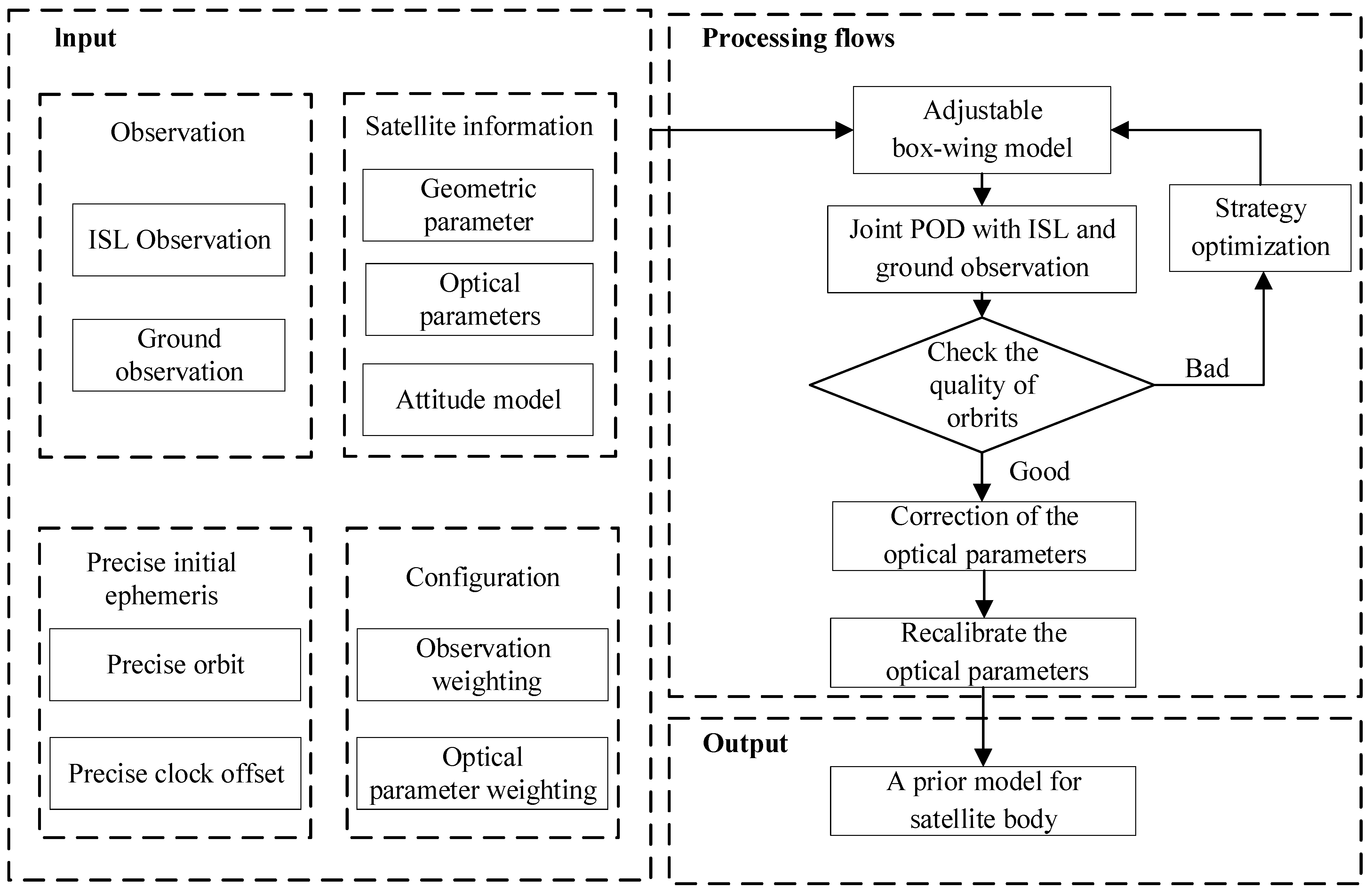
BDS-3 MEO satellites follow a yaw-steering attitude mode [36,37]. Theoretically, the solar panels are always perpendicular to the sunlight and only the +X and ±Z panels of the satellite body are exposed to the Sun. We use the AWB model to construct an a priori model of the satellite body. The optical parameters of +X and ±Z panels are adjusted by POD, respectively. The ECOM1 model was then utilized to describe the constant acceleration of the solar panel as well as other unmodeled SRP accelerations. The refinement process of the a priori SRP model for the BDS-3 MEO body using L-band observation and ISL observations can be seen in Figure 2.
To reduce parameter correlation, an a priori constraint of 0.1 was applied to the parameters of the AWB model. The station-related coordinates, tropospheric delays, and clock offsets were estimated by precise point positioning and fixed throughout the POD processing. The WUM precise orbits were set as the initial orbit to minimize the influence of inaccurate initial orbits on parameter estimation. The constraint of α + ρ + δ = 1 is not applied, as the optical parameters can absorb a portion of the unmodeled effects.

3. Results

This section evaluates the a priori model for the BDS-3 MEO satellite body from a different modeling strategy. The accuracy of the satellite orbits and clock offsets during modeling served as an indirect measure of the quality of the estimated optical parameters. Subsequently, these parameters were employed as a priori models for the satellite body, with the ECOM model compensating for the solar panels and residual SRP. Finally, the accuracy of the orbits and clock offsets estimated with the a priori model was assessed by SLR residual, day boundary difference (DBD), and overlapping Allan deviation (OADEV).

3.1. Optical Parameters

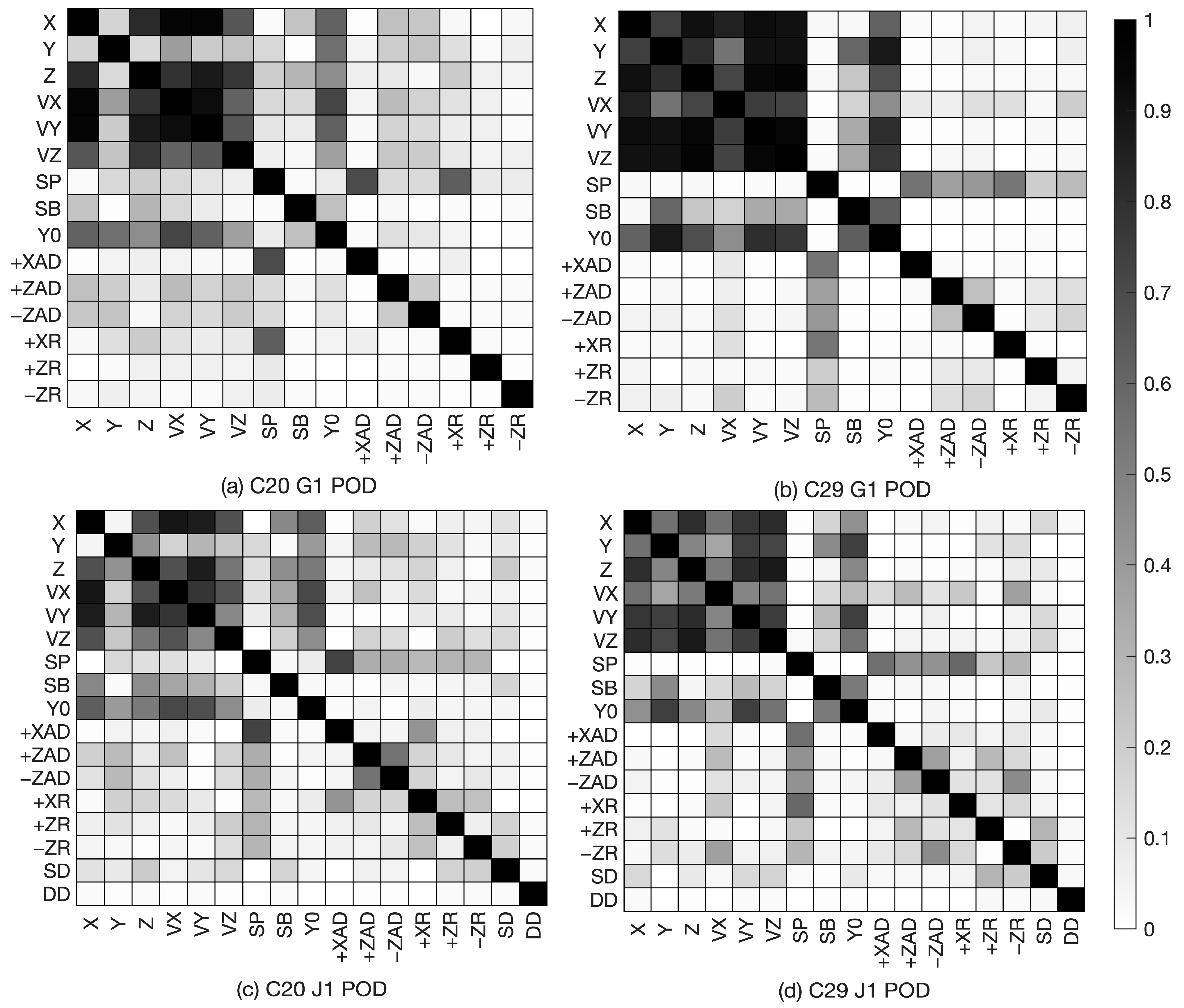
The ABW model can adjust the satellite optical properties by introducing observations. However, there are high correlations among the parameters since the model contains nine parameters. Therefore, special attention should be paid to the correlation between the model parameters when applying this model for SRP modeling. Figure 3 shows the correlation between the parameters of the C20 satellite (β ≈ 51.03°) and the C29 satellite (β ≈ 4.09°) of the solution of DOY 100 in 2020. As seen in Figure 3, the most obvious change after adding the ISL observations is the decrease in the correlation between satellite state parameters of positions and velocities. Moreover, there are some changes in the correlation between the SRP parameters. The correlations related to Y 0 are decreased to some extent. It is also noted that the correlations between some of the parameters slightly increased, e.g., +ZAD vs. −ZAD and +XAD vs. +X. Additionally, the additional introduced hard delay parameters (SD and DD) of ISL equipment have no significant correlation with respect to other parameters. The above analysis shows that the correlation between the estimated parameters is satisfactory. The introduction of ISL observations can reduce the correlation between them, which is helpful for the refinement of the SRP modeling.
To update optical parameters, we performed a statistical analysis based on satellite type. The weighted averages were calculated using only valid estimated orbit arcs, as certain satellite orbit arcs were inaccurately estimated in the modeling period. The optical parameters resulting from the different modeling strategies are presented in Figure 4. It reveals that parameter estimates in the +X direction exhibit better performance, with the sum of parameters ( α + ρ + δ ) approaching 1. Conversely, parameters in the ±Z direction demonstrate higher correlations, leading to large differences among estimates from different strategies. The parameters estimated using ISL data are closer to the α + ρ + δ = 1 condition.

3.2. Orbit and Clock Accuracy of SRP Modeling

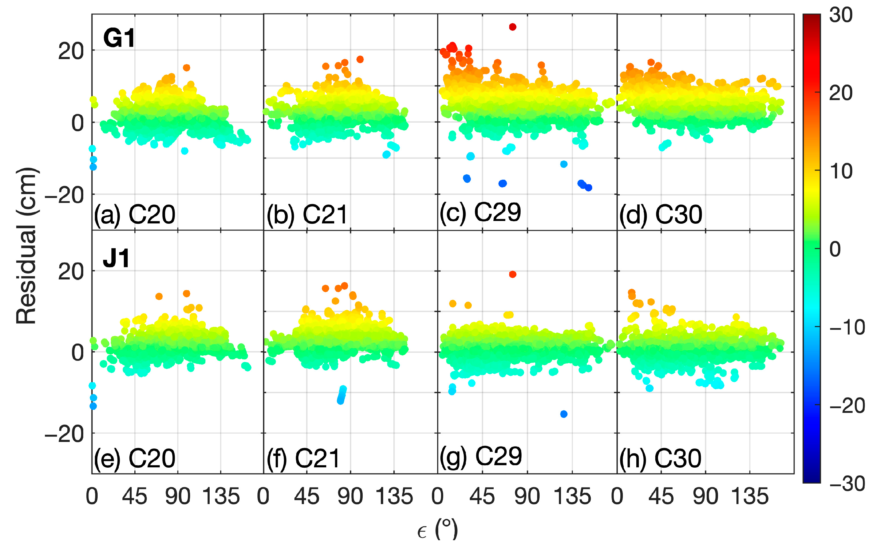
Orbit and clock offset accuracy can be used as an indirect measure of the accuracy of the estimated parameters. Figure 5 illustrates the SLR residuals for G1 and J1 based on the ABW model. Compared with the results of the G1, the ISL observation reduces the dispersion of the residuals. At ε < 45 ° , the upper bound of the SLR residuals for SECM is up to about 20 cm, while the residuals are less than 10 cm for J1, which indicates that the ISL observation can improve the orbit at a low ε angle. Table 4 compares the statistics of the SLR residuals. The inclusion of ISL observations reduces the deviation of SLR residuals by about 3.3 cm for SECM satellites and improves the standard deviation by about 1.3 cm. The root mean squares (RMS) for CAST satellites and SECM satellites are reduced by 10.7% and 58.1%, respectively. The trend of J1 residuals is basically eliminated. The evaluation period revealed a significantly greater improvement in the SECM satellites compared to the CAST satellites. This may be attributed to the larger difference in the X-panel and Z-panel areas of the SECM satellites, leading to a more pronounced systematic trend in the residuals and consequently a more noticeable enhancement.
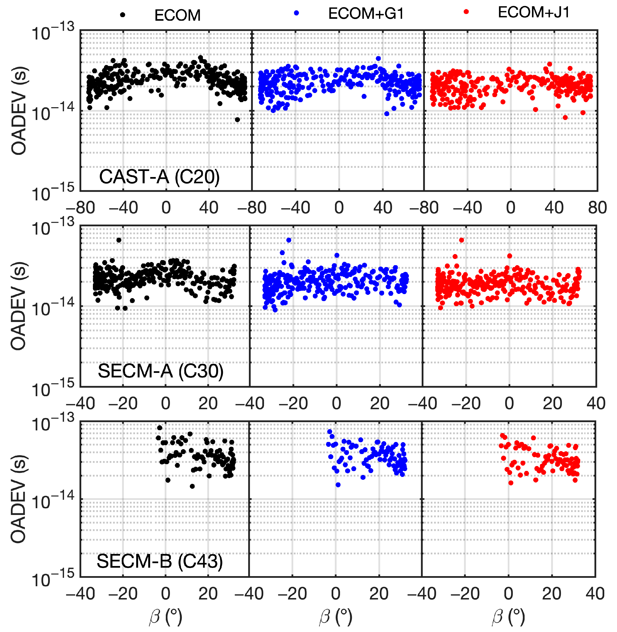
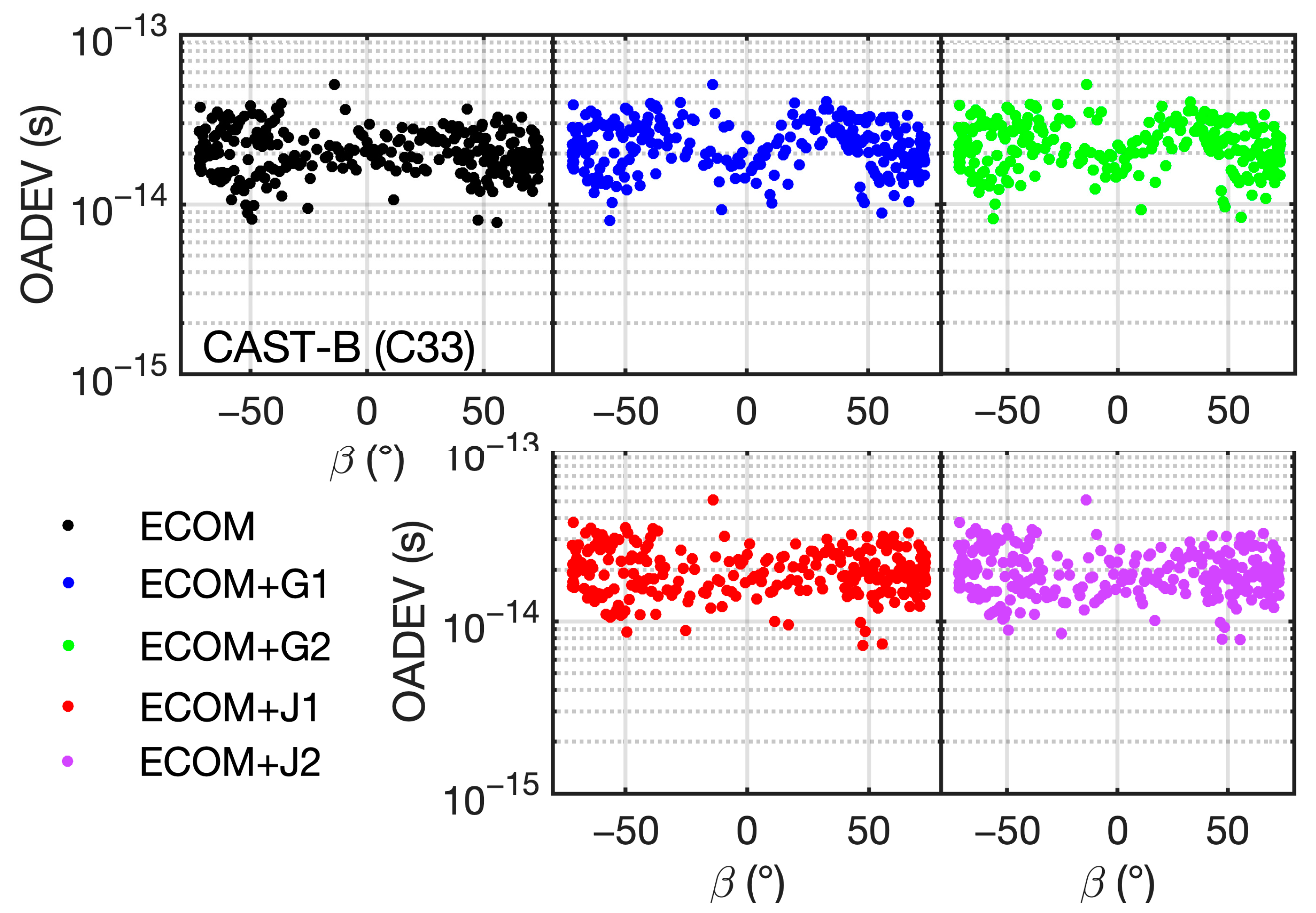
Clock errors are concentrated in the satellite station direction and have a large correlation with the radial errors of the satellite orbit. The stability of the estimated clock offset arcs can be used indirectly to assess the quality of the radial direction of the orbit. We measured the stability of the clock offsets at 9000 s per 1-day orbit arc using OADEV due to the absence of SLR data for other satellites during the evaluation period. The variation in OADEV for 9000 s integration with the solar elevation angle (β angle) was evaluated to assess different modeling strategies. Figure 6 and Figure 7 depict the ADEV values relative to the β angle. The satellites C20, C30, C33, and C43 were plotted as examples to represent four types of MEO satellites. J1/J2 have lower OADEV values and a lesser scatter compared to G1/G2. CAST-A, CAST-B, and SECM-A demonstrate an almost linear β dependence in ADEV values. However, for satellites equipped with a SAR antenna, the enhancement is not significant when considering the SAR antenna. As for the SECM-B satellite, only C43 and C44 satellites are in orbit. C43 shows a clear β-dependency in the J1 strategy (see Figure 7). The orbits of C43 and C44 spanned only 82 days due to the absence of precise WUM orbits as initial orbits. Therefore, no further analyses are performed in this paper.

3.3. Verification of the a Priori Model

Based on the four sets of optical parameters obtained in Figure 4, an a priori SRP model of the rectangular body of the BDS-3 MEO satellite was established. The ECOM model was used to absorb the SRP acceleration introduced by the solar panel and the residual accelerations. To validate the performance of the model, only L-band observations were used in the POD. The test periods and datasets are consistent with the modeling. The accuracy of the a priori model was verified in terms of SLR residual distribution and clock accuracy.
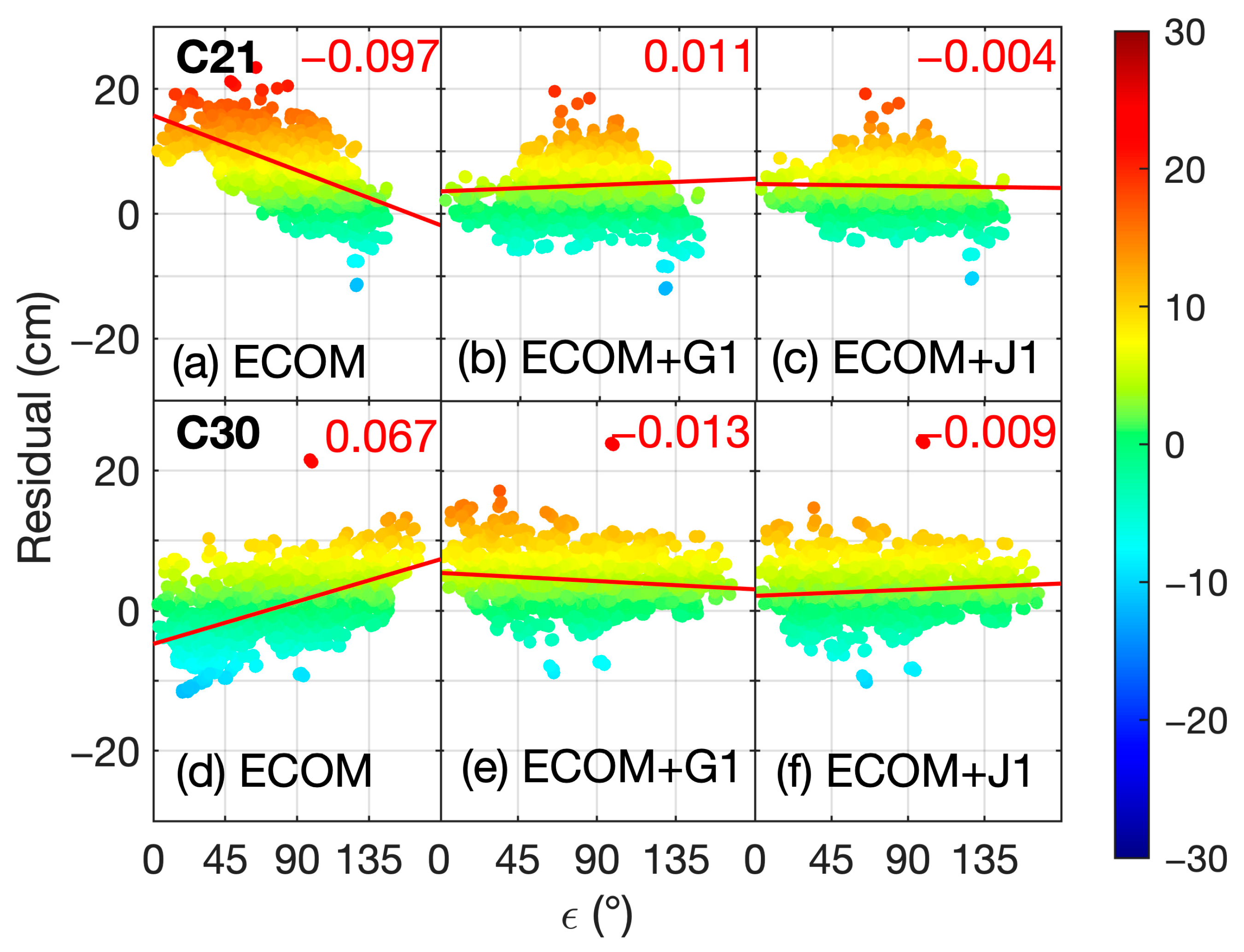
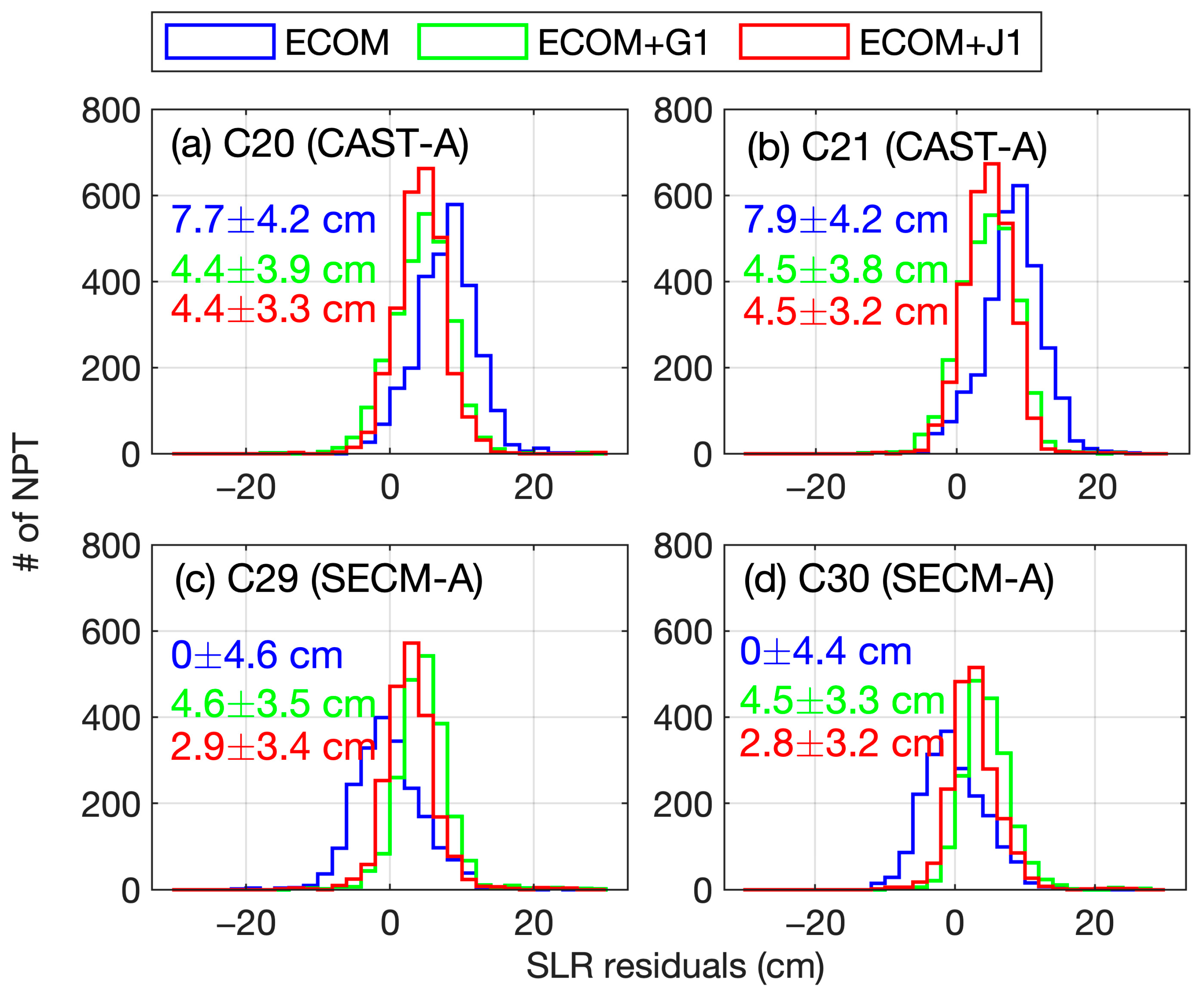
Figure 8 presents a comparison of the SLR residuals derived from the a priori models constructed based on G1 and J1 strategies. A systematic linear trend is depicted using the ECOM model without the a priori satellite body model. The slopes are about −0.097 cm/deg and 0.067 cm/deg for C21 (CAST) and C30 (SECM) satellites, respectively. The a priori model employing the adjusted optical parameters can significantly weaken the systematic trend induced by the ECOM model. Comparison of the a priori models reveals that the a priori model established by both the ISL and L-band observations can almost eliminate the systematic trends in the SLR residuals. The slopes of CAST and SECM are reduced to −0.004 cm/deg and −0.009 cm/deg, which are better than those obtained by using L-band observations. The distribution of SLR residuals is depicted in Figure 9. After adopting the a priori model, the discrete degree was significantly reduced and the a priori model based on J1 was slightly better than the one based on G1. For CAST and SECM satellites, the STD values of the ECOM+J1 strategy decreased from 4.2 cm and 4.6 cm to 3.3 cm and 3.5 cm, respectively. We can also see that the mean value using the a priori model constructed based on J1 is smaller than that of G1. The incorporation of ISLs led to greater improvement in the a priori model for the SECM satellite. This distribution indicates that the a priori model established by J1 is more accurate.
For satellites not observable by SLR stations, Table 5 compares the averaged DBD of their orbits and OADEVs of their clock offsets. The DBD of the CAST satellites did not decrease by employing the ECOM model with the a priori satellite body model, which suggests that the model needs to improve the internal consistency. Furthermore, a slight improvement in DBD was observed for the a priori model established on SAR. Concerning the systematic clock offset trend, Figure 10 demonstrates a sequential decrease in the OADEV trend of C20 and C30 satellites for the ECOM, ECOM+G1, and cJ1 models. For the C33 satellites that consider its SAR panels, the β dependence of OADEV estimated by ECOM+J1/J2 shows less variation compared to ECOM+G/G2 in Figure 11, notably within the range of [−40°, 40°]. Regarding the SECM-B satellite, no specific trends are observed. The average OADEV with the a priori model introducing the ISL is slightly better than that established by the ground station, and the results considering the SAR antenna outperform those without its consideration.

4. Discussion

With a noticeable enhancement in orbit accuracy observed upon integrating ISL observations into data processing, we conducted a comparative analysis of various modeling strategies for the BDS-3’s cuboid satellite body. Previous research indicates that the introduction of ISL data significantly reduces the correlation between ECOM model parameters [26]. However, within the context of the ABW model, while the ISL decreases the correlation among orbit parameters, it also tends to slightly increase the correlation between the optical parameters of the +X/±Z panels to some extent. This may be attributed to the parameter settings of the model. The optical parameters of the satellite buses in the ABW model are correlated, whereas the parameters of ECOM are inherently orthogonal, allowing the ISL to reduce the ECOM parameter correlation by enhancing the geometry observation.
The biases of SLR residuals for the CAST-A satellite based on G1 and J1 are comparable during modeling. The contribution of ISLs is to reduce the dispersion of the SLR residuals. This is well matched with the improved SLR residuals of ECOM+G1/J1 shown in Figure 9. Notably, although ECOM outperforms ECOM+G1/J1 in DBD, the OADEV of the clock offsets demonstrates the superiority of ECOM+J1 over other strategies. For the SECM-A satellites, the a priori model established using J1 can reduce the systematic SLR biases introduced by the G1 model by 1.7 cm. Based on the improvements in DBD and the averaged OADEV values, we found that the use of ISL enhances SECM satellite modeling more effectively than CAST satellites. This is consistent with the understanding that the area differences between SECM satellite X/Z panels results in a more rectangular body shape. However, systematic biases in the SLR residuals persist for both CAST and SECM satellites when using the a priori model compared to the orbits derived from SRP modeling. It is plausible that additional unidentified errors remain uncorrected in the a priori model.
For the CAST satellites carrying SAR antennas, we considered the impact of their self-shadowing. The increased illuminated ±Z area resulting from the SAR antenna was factored in β angles. We found that considering the SAR antenna only slightly improved the DBD accuracy and the OADEV. However, the OADEV series shows a systematic trend with respect to the β angle. This systematic trend was significantly reduced with the a priori model constructed with the introduction of ISL data. With regard to the SECM-B satellites C43 and C44, this study modeled them as separate types of SECM satellites due to the unavailable satellite body structure information. Despite the limited number of orbit arcs within the modeling timeframe, the use of ISLs enhances DBD and OADEV by about 2.2% and 6.7% on the base of the a priori model established by G1. This study suggests that the magnitude of the effects of SAR panels is small, and it can be absorbed with ABW parameters without requiring separate consideration. Additionally, the accuracy of the a priori model may be enhanced if more accurate SAR antenna parameters of CAST-B and SECM-B satellites are released by the official agency.

5. Conclusions

This paper focuses on establishing an a priori SRP model for the BDS-3’s cuboid satellite body to reduce systematic errors in the radial direction. Given the enhancement in orbit accuracy through incorporating ISL observations, we tried to utilize 281-day ISL observation to refine the SRP model for BDS-3. The results are as follows:
  • The correlation between the optical parameters of the +X/±Z panels cannot be significantly decreased even with the ISL observation, due to the parameter settings of the ABW model. Nonetheless, the ISL can still decrease the correlation between orbit parameters, thereby improving the orbit accuracy.
  • An a priori model established for the satellite body can reduce the systematic errors in ECOM orbits, and the model established using ISL observation demonstrates superior performance compared to solely using L-band observations. With the enhanced a priori model, the slopes in the SLR residual of CAST and SECM satellites are reduced from −0.097 cm/deg and 0.067 cm/deg to −0.004 cm/deg and −0.009 cm/deg, respectively. The STD values are reduced with an improvement of 21.8% and 26.6%, respectively. Furthermore, a reduced β-dependent variation is observed in the OADEV of the corresponding clock offset. Nevertheless, systematic biases are still present in the SRL residual when using the a priori model. It is suspected that there are other effects that are yet to be properly accounted for.
  • The impact of self-shadowing from SAR-carrying satellites was considered. The systematic trends within the β < 40 ° decreased with the a priori model established by ISL observation. The orbit accuracy as indicated in the DBD and OADEV of clock offset exhibited a litter improvement. Because of the absence of SAR antenna geometric details from BDS authorities, we propose disregarding the SAR antennas’ impact on the satellites in the current modeling phase.

Author Contributions

Conceptualization, Y.L.; methodology, Y.L.; software, Y.L.; validation, Y.L., Z.L. and R.J.; formal analysis, Y.L., Z.L. and R.J.; investigation, Y.L.; resources, X.X.; data curation, Y.L. and Z.L.; writing—original draft preparation, Y.L.; writing—review and editing, Z.L.; visualization, Y.L.; supervision, X.X.; project administration, Y.L. and X.X.; funding acquisition, Y.L. and X.X. All authors have read and agreed to the published version of the manuscript.

Funding

This research was funded by the National Natural Science Foundation of China, grant number 42204029, 42204028, and the Startup Foundation for Introducing Talent of NUIST, grant number 2022r042.

Data Availability Statement

BDS-3 L-band measurements, WUM precise orbits, and SLR measurements are publicly available from https://cddis.gsfc.nasa.gov/archive (accessed on 1 May 2024), while K-band ISL measurements are accessible with permission from the China Satellite Navigation Office (CNSO).

Acknowledgments

We gratefully acknowledge the IGS Multi-GNSS Experiment (MGEX) and the International GNSS Monitoring and Assessment System (iGMAS) for supplying BDS-3 observations, as well as the ILRS for providing SLR observations.

Conflicts of Interest

The authors declare no conflicts of interest.

References

  1. Yang, Y.; Gao, W.; Guo, S.; Mao, Y.; Yang, Y. Introduction to BeiDou-3 Navigation Satellite System. Navigation 2019, 66, 7–18. [Google Scholar] [CrossRef]
  2. Yang, Y.; Mao, Y.; Sun, B. Basic Performance and Future Developments of BeiDou Global Navigation Satellite System. Satell. Navig. 2020, 1, 1. [Google Scholar] [CrossRef]
  3. Xia, L.; Lin, B.; Liu, Y.; Xiong, S.; Bai, T. Satellite Geometry and Attitude Mode of BDS-3 MEO Satellites Developed by SECM. In Proceedings of the 31st International Technical Meeting of the Satellite Division of The Institute of Navigation (ION GNSS+ 2018), Miami, FL, USA, 24–28 September 2018; pp. 1268–1289. [Google Scholar]
  4. Yang, Y.; Yang, Y.; Hu, X.; Chen, J.; Guo, R.; Tang, C.; Zhou, S.; Zhao, L.; Xu, J. Inter-Satellite Link Enhanced Orbit Determination for BeiDou-3. J. Navig. 2019, 73, 115–130. [Google Scholar] [CrossRef]
  5. Lv, Y.; Geng, T.; Zhao, Q.; Xie, X.; Zhou, R. Initial Assessment of BDS-3 Preliminary System Signal-in-Space Range Error. GPS Solut. 2019, 24, 16. [Google Scholar] [CrossRef]
  6. Steigenberger, P.; Deng, Z.; Guo, J.; Prange, L.; Song, S.; Montenbruck, O. BeiDou-3 Orbit and Clock Quality of the IGS Multi-GNSS Pilot Project. Adv. Space Res. 2023, 71, 355–368. [Google Scholar] [CrossRef]
  7. Guo, J.; Wang, C.; Chen, G.; Xu, X.; Zhao, Q. BDS-3 Precise Orbit and Clock Solution at Wuhan University: Status and Improvement. J. Geod. 2023, 97, 15. [Google Scholar] [CrossRef]
  8. Yan, X.; Liu, C.; Huang, G.; Zhang, Q.; Wang, L.; Qin, Z.; Xie, S. A Priori Solar Radiation Pressure Model for BeiDou-3 MEO Satellites. Remote Sens. 2019, 11, 1605. [Google Scholar] [CrossRef]
  9. Fliegel, H.; Feess, W.; Layton, W.; Verdun, A. The GPS radiation force model. In Proceedings of the First International Symposium on Precise Positioning with the Global Positioning System, Rockville, MD, USA, 15–19 April 1985; pp. 113–119. [Google Scholar]
  10. Fliegel, H.; Gallini, T. Radiation pressure models for Block II GPS satellites. In Proceedings of the Fifth International Geodetic Symposium on Satellite Positioning, Rockville, MD, USA, 13–17 March 1989; pp. 789–798. [Google Scholar]
  11. Fliegel, H.; Gallini, T.; Swift, E. Global Positioning System Radiation Force Model for Geodetic Applications. J. Geophys. Res. Solid Earth 1992, 97, 559–568. [Google Scholar] [CrossRef]
  12. Fliegel, H.; Gallini, T. Solar Force Modeling of Block IIR Global Positioning System Satellites. J. Spacecr. Rocket. 1996, 33, 863–866. [Google Scholar] [CrossRef]
  13. Marshall, J.; Luthcke, S. Modeling Radiation Forces Acting on Topex/Poseidon for Precision Orbit Determination. J. Spacecr. Rocket. 1994, 31, 99–105. [Google Scholar] [CrossRef]
  14. Rodriguez-Solano, C.J.; Hugentobler, U.; Steigenberger, P. Adjustable box-wing model for solar radiation pressure impacting GPS satellites. Adv. Space Res. 2012, 49, 1113–1128. [Google Scholar] [CrossRef]
  15. Beutler, G.; Brockmann, E.; Gurtner, W.; Hugentobler, U.; Mervart, L.; Rothacher, M.; Verdun, A. Extended orbit modeling techniques at the CODE processing center of the international GPS service for geodynamics (IGS): Theory and initial results. Manuscr. Geod. 1994, 19, 367–386. [Google Scholar]
  16. Springer, T.A.; Beutler, G.; Rothacher, M. A New Solar Radiation Pressure Model for GPS Satellites. GPS Solut. 1999, 2, 50–62. [Google Scholar] [CrossRef]
  17. Arnold, D.; Meindl, M.; Beutler, G.; Dach, R.; Schaer, S.; Lutz, S.; Prange, L.; Sośnica, K.; Mervart, L.; Jäggi, A. CODE’s New Solar Radiation Pressure Model for GNSS Orbit Determination. J. Geod. 2015, 89, 775–791. [Google Scholar] [CrossRef]
  18. China Satellite Navigation Office. Definitions and Descriptions of BDS/GNSS Satellite Parameters for High Precision Application. Available online: https://ilrs.cddis.eosdis.nasa.gov/docs/2019/BeiDou_MetaData_191201.cn.en.pdf (accessed on 1 May 2024).
  19. Duan, B.; Hugentobler, U.; Selmke, I.; Marz, S.; Killian, M.; Rott, M. BeiDou Satellite Radiation Force Models for Precise Orbit Determination and Geodetic Applications. IEEE T. Aero. Elec. Syst. 2022, 58, 2823–2836. [Google Scholar] [CrossRef]
  20. Chen, Z.; Wu, X. General design of the third generation BeiDou navigation satellite system. J. Nanjing Univ. Aeronaut. Astronaut. (Chin.) 2020, 52, 835–845. [Google Scholar] [CrossRef]
  21. China Satellite Navigation Office (CSNO), BeiDou Navigation Satellite System Signal in Space Interface Control Document Search and Rescue Service (Version 1.0). 2020. Available online: http://www.beidou.gov.cn/xt/gfxz/202008/P020200803362068698004.pdf (accessed on 1 May 2024).
  22. Li, X.; Yuan, Y.; Zhu, Y.; Jiao, W.; Bian, L.; Li, X.; Zhang, K. Improving BDS-3 Precise Orbit Determination for Medium Earth Orbit Satellites. GPS Solut. 2020, 24, 53. [Google Scholar] [CrossRef]
  23. Ruan, R.; Jia, X.; Feng, L.; Wang, L.; Zhang, F. Modeling non-conservative forces for BDS-3 MEO satellites. Acta Geod. Cartogr. Sin. (Chin.) 2022, 51, 1862G1869. [Google Scholar] [CrossRef]
  24. Li, J.; Yuan, Y.; Huang, S.; Liu, C.; Lou, J.; Li, X. Examination and enhancement of solar radiation pressure model for BDS-3 satellites. In Proceedings of the EGU General Assembly 2021, Vienna, Austria, 19–30 April 2021; Available online: https://ui.adsabs.harvard.edu/abs/2021EGUGA..23.8307L/abstract (accessed on 30 August 2024).
  25. Li, P.; Zhang, H.; Xie, M.; Zhao, D. A Study of Solar Radiation Pressure Model in BDS-3 Precise Orbit Determination. Chin. Astron. Astrophys. 2023, 47, 894–911. [Google Scholar] [CrossRef]
  26. Lv, Y.; Geng, T.; Zhao, Q.; Zhang, C. Contribution of Intersatellite Link Measurements to ECOM Solar Radiation Pressure Estimation on the BDS-3 MEO Satellite. GPS Solut. 2024, 28, 47. [Google Scholar] [CrossRef]
  27. Lv, Y.; Geng, T.; Zhao, Q.; Xie, X.; Zhang, F.; Wang, X. Evaluation of BDS-3 Orbit Determination Strategies Using Ground-Tracking and Inter-Satellite Link Observation. Remote Sens. 2020, 12, 2647. [Google Scholar] [CrossRef]
  28. Xie, X.; Geng, T.; Zhao, Q.; Lv, Y.; Cai, H.; Liu, J. Orbit and Clock Analysis of BDS-3 Satellites Using Inter-Satellite Link Observations. J. Geod. 2020, 94, 64. [Google Scholar] [CrossRef]
  29. Yang, D.; Yang, J.; Li, G.; Zhou, Y.; Tang, C. Globalization Highlight: Orbit Determination Using BeiDou Inter-Satellite Ranging Measurements. GPS Solut. 2017, 21, 1395–1404. [Google Scholar] [CrossRef]
  30. Wang, H.; Xie, J.; Zhang, J.; Wang, Z. Performance Analysis and Progress of Inter-Satellite-Link of Beidou System. In Proceedings of the 30th International Technical Meeting of the Satellite Division of the Institute of Navigation (ION GNSS+ 2017), Portland, OR, USA, 25–29 September 2017; pp. 1178–1185. [Google Scholar] [CrossRef]
  31. Pan, J.; Hu, X.; Zhou, S.; Tang, C.; Guo, R.; Zhu, L.; Tang, G.; Hu, G. Time Synchronization of New-Generation BDS Satellites Using Inter-Satellite Link Measurements. Adv. Space Res. 2018, 61, 145–153. [Google Scholar] [CrossRef]
  32. Petit, G.; Luzum, B. IERS conventions (2010) (No. IERS-TN-36); IERS Convention Center: Frankfurt, Germany, 2010; Available online: https://iers-conventions.obspm.fr/content/tn36.pdf (accessed on 30 August 2024).
  33. Pavlis, N.K.; Holmes, S.A.; Kenyon, S.C.; Factor, J.K. The Development and Evaluation of the Earth Gravitational Model 2008 (EGM2008). J. Geophys. Res. Solid Earth 2012, 117. [Google Scholar] [CrossRef]
  34. Rodriguez-Solano, C.J. Impact of the Albedo Modeling on GPS Orbits. Ph.D. Thesis, Technische Universität München, München, Germany, 2009. [Google Scholar]
  35. Steigenberger, P.; Thoelert, S. Initial BDS-3 transmit power analysis (with BDS-2 gain pattern). 2020. [Google Scholar]
  36. Xie, X.; Geng, T.; Ma, Z.; Chen, L.; Liu, J. Estimation and Analysis of BDS-3 Satellite Yaw Attitude Using Inter-Satellite Link Observations. GPS Solut. 2022, 26, 106. [Google Scholar] [CrossRef]
  37. Yang, C.; Guo, J.; Zhao, Q. Yaw Attitudes for BDS-3 IGSO and MEO Satellites: Estimation, Validation and Modeling with Intersatellite Link Observations. J. Geod. 2023, 97, 6. [Google Scholar] [CrossRef]
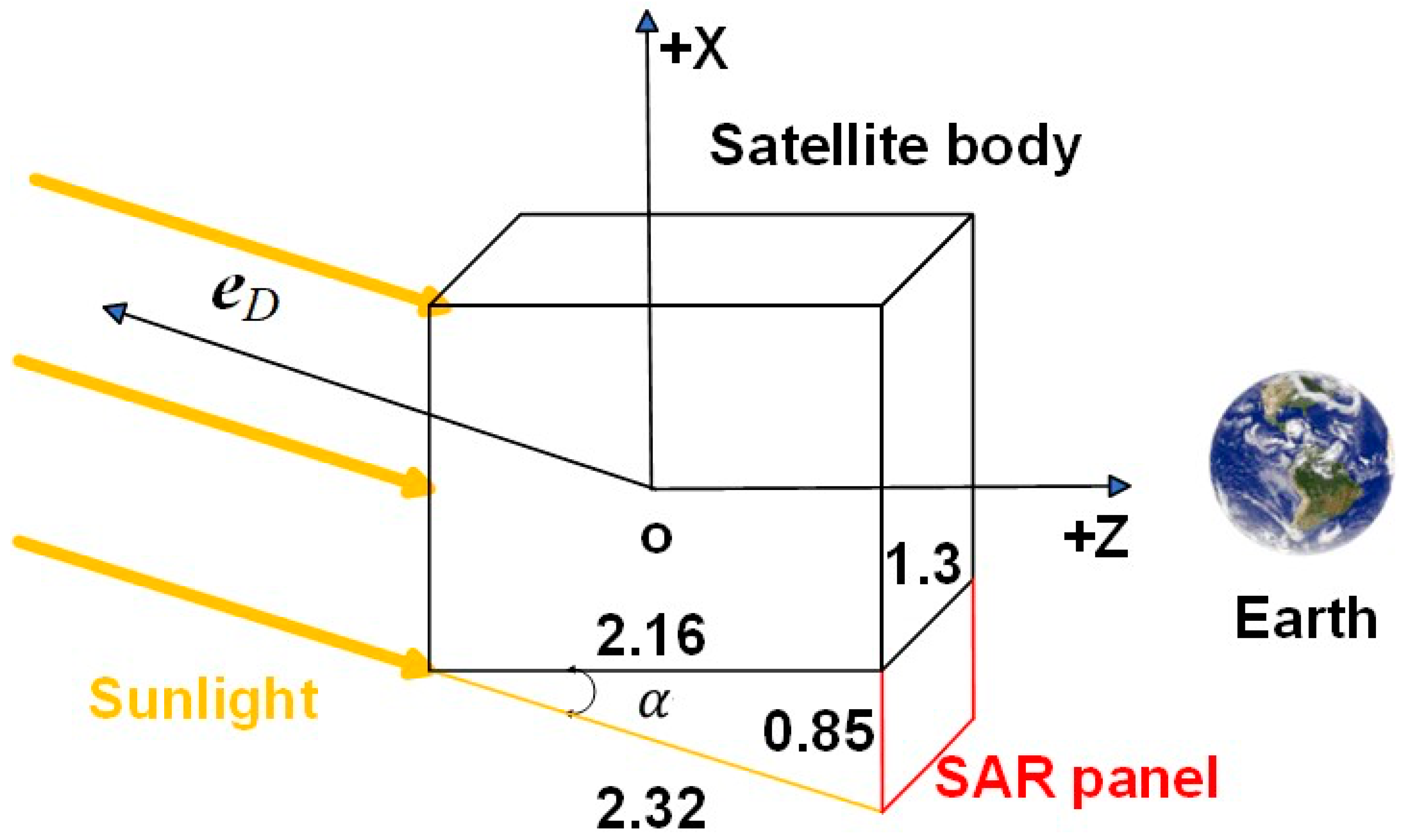
Figure 1. Dimensions of the satellite body and its shadow on the panel (unit: m).
Remotesensing 16 03900 g001
Figure 2. Flowchart for the refinement of SRP models of BDS-3 MEO satellite.
Remotesensing 16 03900 g002
Figure 3. Correlation between the parameters for CAST (C20) satellite and SECM (C29) satellite obtained by the G1 and J1.
Remotesensing 16 03900 g003
Figure 4. Optical parameter estimated by strategy G1 (blue), G2 (purple), J1 (red), and J2 (green).
Remotesensing 16 03900 g004
Figure 5. SLR residual dependent on ε angle for satellite without SAR antenna. The first row represents G1 estimates, and the second row represents J1 estimates.
Remotesensing 16 03900 g005
Figure 6. OADEV at 9000 s of CAST-A (C20) and SECM-A (C30) with respect to the β angle.
Remotesensing 16 03900 g006
Figure 7. OADEV at 9000 s of CAST-B (C33) and SECM-B (C43) with respect to the β angle.
Remotesensing 16 03900 g007
Figure 8. SLR residual estimated by ECOM (left column), ECOM+G1 (middle column), and ECOM+J1 (right column) dependent on ε angle. The red line represents the linear trend line, with the slope value (red font) denoted in cm/deg.
Remotesensing 16 03900 g008
Figure 9. SLR residual distribution based on ECOM (blue), ECOM+G1 (green), and ECOM+J1 (red).
Remotesensing 16 03900 g009
Figure 10. OADEV at 9000 s of CAST-A (C20), SECM-A (C30), and SECM-B (C43) satellites with respect to the β angle.
Remotesensing 16 03900 g010
Figure 11. OADEV at 9000 s of CAST-B (C33) satellite with respect to the β angle.
Remotesensing 16 03900 g011
Table 1. Geometric and optical information of BDS-3 MEO satellites.
Sat. TypeSat.Panel Area   ( m 2 ) α + δ ρ
CAST-AC19, C20, C21, C22, C23, C24, C36, C37, C41, C42+X1.250.3500.650
+Z2.590.9200.080
−Z2.590.3500.650
CAST-BC32, C33, C45, C46+X1.250.3500.650
+Z2.590.9200.080
−Z2.590.3500.650
SECM-AC25, C26, C27, C28, C29, C30, C34, C35+X1.250.2000.800
+Z2.590.2000.800
−Z2.590.2000.800
SECM-BC43, C44+X1.240.2000.800
+Z2.570.2000.800
−Z2.570.2000.800
Table 2. SRP modeling strategy for BDS-3 MEO satellite.
StrategyObservationSAR Antenna
G1L-bandUnconsidered
J1L-band, Ka-bandUnconsidered
G2L-bandConsidered
J2L-band, Ka-bandConsidered
Table 3. Dynamical model for SRP modeling.
ItemsModels
Tide displacementSolid Earth tide, pole tide, and ocean tide loading [32]
Relativity effectSchwarzschild and Lense-Thirring
GeopotentialEGM2008 up to 12 × 12 degrees and orders [33]
N-body gravitationJet Propulsion Laboratory (JPL) DE405 ephemeris
Earth radiation pressure Applied [34]
Antenna thrust310 W for CAST satellite and 280 W for SECM satellite [35]
Table 4. SLR residuals of G1 and J1 strategies of SRP modeling (unit: cm).
# of Normal PointG1J1
BiasSTDRMSBiasSTDRMS
C2026461.92.83.42.12.12.9
C2127463.02.84.13.02.33.8
C2920324.94.26.40.52.42.5
C3018484.93.46.00.72.62.7
Table 5. DBD and OADEV at OADEV at 9000 s for different POD strategies.
Sat. TypeStrategyAlong (cm)Cross (cm)Radial (cm)3D (cm)OADEV (s)
CAST-AECOM20.57.35.422.52.47 × 10−14
ECOM+G121.89.16.724.52.67 × 10−14
ECOM+J121.88.26.024.02.36 × 10−14
CAST-BECOM27.28.88.529.92.75 × 10−14
ECOM+G128.510.39.631.83.43 × 10−14
ECOM+G228.310.29.531.63.40 × 10−14
ECOM+J127.58.98.630.22.81 × 10−14
ECOM+J227.48.88.530.12.75 × 10−14
SECM-AECOM30.26.35.331.32.36 × 10−14
ECOM+G129.67.15.230.92.12 × 10−14
ECOM+J129.06.45.230.21.95 × 10−14
SECM-BECOM34.510.39.437.23.53 × 10−14
ECOM+G133.810.89.136.63.41 × 10−14
ECOM+J133.210.19.135.83.18 × 10−14
Disclaimer/Publisher’s Note: The statements, opinions and data contained in all publications are solely those of the individual author(s) and contributor(s) and not of MDPI and/or the editor(s). MDPI and/or the editor(s) disclaim responsibility for any injury to people or property resulting from any ideas, methods, instructions or products referred to in the content.