Abstract
The fusion of infrared and visible images together can fully leverage the respective advantages of each, providing a more comprehensive and richer set of information. This is applicable in various fields such as military surveillance, night navigation, environmental monitoring, etc. In this paper, a novel infrared and visible image fusion method based on sparse representation and guided filtering in Laplacian pyramid (LP) domain is introduced. The source images are decomposed into low- and high-frequency bands by the LP, respectively. Sparse representation has achieved significant effectiveness in image fusion, and it is used to process the low-frequency band; the guided filtering has excellent edge-preserving effects and can effectively maintain the spatial continuity of the high-frequency band. Therefore, guided filtering combined with the weighted sum of eight-neighborhood-based modified Laplacian (WSEML) is used to process high-frequency bands. Finally, the inverse LP transform is used to reconstruct the fused image. We conducted simulation experiments on the publicly available TNO dataset to validate the superiority of our proposed algorithm in fusing infrared and visible images. Our algorithm preserves both the thermal radiation characteristics of the infrared image and the detailed features of the visible image.
1. Introduction
Infrared and visible image fusion is a process that integrates the complementary information from infrared (IR) and visible light images to produce a single image that is more informative and suitable for human perception or automated analysis tasks [1]. This technique leverages the distinct advantages of both imaging modalities to enhance the visibility of features that are not apparent in either image alone [2,3].
Unlike visible light images, infrared images capture the thermal radiation emitted by objects. This allows for the detection of living beings, machinery, and other heat sources, even in total darkness or through obstructions like smoke and fog. IR imaging is invaluable for applications requiring visibility in low-light conditions, such as night-time surveillance, search and rescue operations, and wildlife observation [4].
Visible light images provide high-resolution details and color information, which are crucial for human interpretation and understanding of a scene. From photography to video surveillance, visible light imaging is the most common form of imaging, offering a straightforward depiction of the environment as perceived by the human eye. The fusion process integrates the thermal information from infrared images with the detail and color information from visible images [5,6,7,8]. This results in images that highlight both the thermal signatures and the detailed scene information. By combining these two types of images, the fused image enhances the ability to detect and recognize subjects and objects in various conditions, including complete darkness, smoke, fog, and camouflage situations.
Various algorithms and techniques, including multi-resolution analysis, image decomposition, and feature-based methods, have been developed to fuse the images. A major challenge in image fusion is to maintain and highlight the essential details from both source images in the combined image, while avoiding artifacts and ensuring that no crucial information is lost [9,10,11,12,13,14,15,16,17]. For some applications, such as surveillance and automotive safety, the ability to process and fuse images in real time is crucial. This creates difficulties in terms of processing efficiency and the fine-tuning of algorithms.
During the fusion process, some information may be lost or confused, especially in areas with strong contrast or rich details, where the fusion algorithm might not fully retain the information from each image. Additionally, noise or artifacts may be introduced during the fusion process, affecting the quality of the final image. To enhance the performance of the fused image in terms of both thermal radiation characteristics and detail clarity, a fusion method utilizing sparse representation and guided filtering in the Laplacian pyramid domain is constructed. Sparse representation has demonstrated excellent results in image fusion; it is used to process the low-frequency sub-bands, and guided filtering combined with the weighted sum of eight-neighborhood-based modified Laplacian (WSEML) is utilized to process the high-frequency sub-bands. Through experiments and validation on the publicly available TNO dataset, our algorithm has achieved significant fusion effects, incorporating both infrared characteristics and scene details. This is advantageous for subsequent target detection and recognition tasks.
The paper is structured as follows: Section 2 reviews related research. Section 3 introduces the Laplacian pyramid transform. Section 4 details the proposed fusion approach. Section 5 shows the experimental results and discussion. Finally, Section 6 concludes the paper. This structure ensures a clear progression through the background research, foundational concepts, algorithmic details, empirical findings, and concluding remarks, thereby comprehensively addressing the topic of image fusion in the Laplacian pyramid domain.
2. Related Works
2.1. Deep Learning on Image Fusion
Deep learning has achieved significant results in the field of image processing, with popular algorithms including CNNs [18], GANs [19], swin transformer [20,21], vision transformer [22], and mamba [23]. Deep learning has significantly advanced the field of image fusion by introducing models that can learn complex representations and fusion rules from data, leading to superior fusion performance compared with traditional techniques. Deep-learning models can automatically extract and merge the most pertinent features from both infrared and visible images. This process produces fused images that effectively combine the thermal information from infrared images with the detailed texture and color from visible images [24,25,26].
CNNs are widely employed as deep-learning models for image fusion. They excel at capturing spatial hierarchies in images through their deep architecture, making them ideal for tasks that involve spatial data, like images. In the context of image fusion, CNNs can be trained to identify and merge the salient features from both infrared and visible images, ensuring that the fused image retains critical information from both sources [27]. Liu et al. [28] introduced the fusion of infrared and visible images using CNNs. Their experimental findings showcase that this approach attains cutting-edge outcomes in both visual quality and objective metrics. Similarly, Yang et al. [29] devised a method for image fusion leveraging multi-scale convolutional neural networks alongside saliency weight maps.
GANs have also been applied to image fusion with promising results [30,31]. A GAN consists of two networks: a generator that creates images and a discriminator that evaluates them. For image fusion, the generator can be trained to produce fused images from input images, while the discriminator ensures that the fused images are indistinguishable from real images in terms of quality and information content. This approach can result in high-quality fused images that effectively blend the characteristics of both modalities. Change et al. [32] presented a GAN model incorporating dual fusion paths and a U-type discriminator. Experimental findings illustrate that this approach outperforms other methods.
Deep learning offers a powerful framework for image fusion, with the potential to significantly enhance the quality and usefulness of fused images across a wide range of applications. Ongoing research in this field focuses on developing more efficient, adaptable, and interpretable models that can provide even better fusion results.
2.2. Traditional Methods of Image Fusion
Traditional methods for image fusion focus on combining the complementary information from source images to enhance the visibility of features and improve the overall quality of the resulting image. These techniques are generally categorized via the domain in which the fusion takes place: transform- and spatial-domain methods [33,34,35,36,37].
In transform-domain methods, Chen et al. [38] introduced a spatial-frequency collaborative fusion framework for image fusion; this algorithm utilizes the properties of nonsubsampled shearlet transform for decomposition and reconstruction. Chen et al. [39] introduced a fusion approach tailored for image fusion, emphasizing edge consistency and correlation-driven integration. Through nonsubsampled shearlet transform decomposition, detail layers are acquired housing image details and textures alongside a base layer containing primary features. Li et al. [40] introduced the method for fusing infrared and visible images, leveraging low-pass filtering and sparse representation. Chen et al. [41] introduced the multi-focus image fusion with complex sparse representation (CSR); this model leverages the properties of hypercomplex signals to obtain directional information from real-valued signals by extending them to complex form. It then decomposes these directional components into sparse coefficients using specific directional dictionaries. Unlike traditional SR models, this approach excels at capturing geometric structures in images. This is because CSR coefficients offer accurate measurements of detailed information along particular directions.
In spatial domain methods, Li et al. [42] introduced a neural-network-based approach to assess focus properties using measures like spatial frequency, visibility, and edge features within the source image blocks.
3. Laplacian Pyramid Transform
The Laplacian pyramid of an image can be obtained by computing the difference between every two consecutive layers of the Gaussian pyramid [43,44,45]. Suppose represents a matrix of an image, and represents the layer of the Gaussian pyramid decomposition of the image. Similarly, the layer of the Gaussian pyramid is , where the 0th layer is the image itself. The definition of is as follows [44]:
where is the maximum number of layers in the Gaussian pyramid decomposition; and represent the number of rows and columns of the layer image of the Gaussian pyramid, respectively. is a low-pass window function of size [44,45]:
To compute the difference between the layer image and the layer image in the Gaussian pyramid, it is necessary to upsample the low-resolution image to match the size of the high-resolution image . Opposite to the process of image downsampling (Reduce), the operation defined for image upsampling is called Expand:
where and have the same dimensions. The specific operation is achieved by interpolating and enlarging the layer image, , as defined in Equation (3):
where
From Equation (4), it can be inferred that the newly interpolated pixels between the original pixels are determined by the weighted average of the original pixel intensities.
At this point, the difference between the expanded image and the layer image in the pyramid can be obtained from the following equation:
The above expression generates the level of the Laplacian pyramid. Since is obtained from through low-pass filtering and downsampling, the details in are significantly fewer than those in , so the detail information contained in the interpolated of will still be less than . , as the difference between and , also reflects the information difference between the two layers of images in the Gaussian pyramid and . It contains the high-frequency detail information lost when is obtained through the blurring and downsampling of .
The complete definition of the Laplacian pyramid is as follows:
Thus, can form the Laplacian pyramid of the image, where each layer is the difference between the corresponding layers of the Gaussian pyramid and its upsampled version. This process is akin to bandpass filtering; therefore, the Laplacian pyramid can also be referred to as bandpass tower decomposition.
The decomposition process of the Laplacian pyramid can be summarized into four steps: low-pass filtering, downsampling, interpolation, and bandpass filtering. Figure 1 shows the decomposition and reconstruction process of the Laplacian pyramid transform. A series of pyramid images obtained through Laplacian decomposition can be reconstructed into the original image through an inverse transformation process. Below, we derive the reconstruction method based on Equation (7):
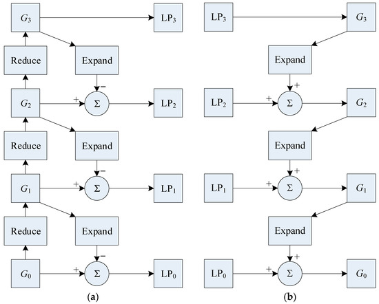
Figure 1.
Laplacian pyramid. (a) Three-level Laplacian pyramid decomposition diagram; (b) Three-level Laplacian reconstruction diagram.
In summary, the reconstruction formula for the Laplacian pyramid can be expressed as
4. Proposed Fusion Method
In this section, we present a technique for fusing infrared and visible images using sparse representation and guided filtering within the Laplacian pyramid framework. The method involves four main stages: image decomposition, low-frequency fusion, high-frequency fusion, and image reconstruction. The structure of the proposed method is shown in Figure 2.
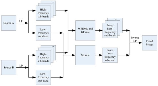
Figure 2.
The structure of the proposed method.
4.1. Image Decomposition
The original image undergoes decomposition into a Laplacian pyramid (LP), yielding a low-frequency band and a series of high-frequency bands. This LP transform is applied separately to the source images A and B, resulting in and , which represent the layer of the source images. When , and are the decomposed top-level images (i.e., low-frequency information).
4.2. Low-Frequency Fusion
The low-frequency band effectively encapsulates the general structure and energy of the image. Sparse representation [1] has demonstrated efficacy in image fusion tasks; hence, it is employed to process the low-frequency band.
The sliding window technique is used to partition and into image patches with the size , from upper left to lower right, with the step length of pixels. Let us denote that there are patches represented as and in and , respectively.
For each position , rearrange into column vectors , and then normalize each vector’s mean value to zero to generate using the following equations [1]:
where 1 depicts an all-one valued vector, and and are the mean values of all the elements in and , respectively.
To compute the sparse coefficient vectors of , we employ the orthogonal matching pursuit (OMP) technique, applying the following formulas:
Here, represents the learned dictionary obtained through the K-singular value decomposition (K-SVD) approach.
Next, and are combined using the “max-L1” rule to produce the fused sparse vector:
The fused results of and can be calculated using the following method:
where the merged mean value can be computed as follows:
The above process is iterated for all the source image patches in and to generate all fused vectors . Let denotes the low-pass fused result. For each , reshape it into a patch , and then plug into its original position in . As the patches are overlapped, each pixel’s value in is averaged over its accumulation times.
4.3. High-Frequency Fusion
The high-frequency bands contain detailed information. The activity level measure, named WSEML, is defined as follows [46]:
where , the normalized model of , is defined as follows:
and the is computed by
The two zero-value matrixes mapA and mapB are initialized, and the matrixes are computed by
Guided filtering, denoted as , is a linear filtering technique [47,48]. Here, the parameters that control the size of the filter kernel and the extent of blur are represented by and , respectively. and depict the input image and guidance image, respectively. To enhance the spatial continuity of the high-pass bands in the context of using guided filtering on mapA and mapB, we utilize the corresponding high-pass bands and as the guidance images.
where mapA and mapB should be normalized, and the fused high-pass bands are calculated by
4.4. Image Reconstruction
Perform the corresponding inverse LP to reconstruct the final fused image.
5. Experimental Results and Discussion
5.1. Experimental Setup
In this section, we conducted simulation experiments using the TNO public dataset [49] and compared them through qualitative and quantitative evaluations. Figure 3 shows the examples from the TNO dataset. We compared our algorithm with eight other image fusion algorithms, namely, ICA [50], ADKLT [51], MFSD [52], MDLatLRR [53], PMGI [54], RFNNest [55], EgeFusion [56], and LEDIF [57]. For quantitative evaluation, we adopted 10 commonly used evaluation metrics to assess the effectiveness of the algorithm, namely, the edge-based similarity measurement [58,59,60,61,62,63], the human-perception-inspired metric [64,65], the structural-similarity-based metric [64], the feature mutual information metric [66], the gradient-based metric [64], the mutual information metric [58,67], the nonlinear correlation information entropy [64], the normalized mutual information [64], the phase-congruency-based metric [64], and the structural-similarity-based metric introduced by Yang et al. [64,68,69]. computes and measures the amount of edge information transferred from the source images to the fused images using a Sobel edge detector. is a perceptual-fusion metric based on human visual system (HVS) models. takes the original images and the edge images into consideration at the same time. calculates the regional mutual information between corresponding windows in the fused image and the two source images. is obtained from the weighted average of the edge information preservation values. computes how much information from the source images is transferred to the fused image. is an information-theory-based metric. is a quantitative measure of the mutual dependence of two variables. provides an absolute measure of image features. is a fusion metric based on SSIM. A higher index value indicates the algorithm’s superiority.
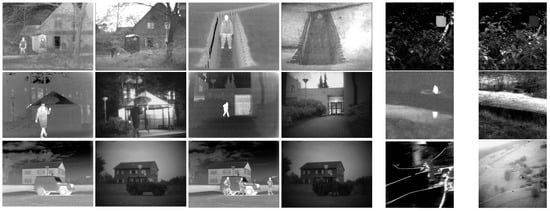
Figure 3.
Examples from the TNO dataset.
The parameters for the compared algorithms correspond to the default parameters in the respective articles. For our method, the parameters are as follows: , ; the dictionary size is 256, with K-SVD iterated 180 times. Patch size is 6 × 6, step length is 1, and error tolerance is 0.1 [1].
5.2. Analysis of LP Decomposition Levels
Figure 4 shows the fusion results of LP with different decomposition levels. From the figure, it can be observed that the fusion effects in Figure 4a–c are poor, with severe artifacts. The fusion results in Figure 4d–f are relatively similar. Table 1 provides evaluation metrics for 42 image pairs under different LP decomposition levels. Since the fusion results are poor for decomposition levels 1–3, we first exclude these settings. Comparing the average metric values for decomposition levels 4–6, we see that at level 4, five metrics are optimal. Therefore, we set the LP decomposition level to 4.
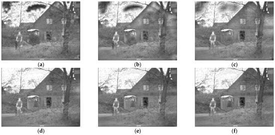
Figure 4.
Fusion results of different decomposition levels in LP. (a) 1 level; (b) 2 level; (c) 3 level; (d) 4 level; (e) 5 level; (f) 6 level.

Table 1.
The average objective evaluation of different LP decomposition levels on 42 pairs of data from the TNO dataset.
5.3. Qualitative and Quantitative Analysis
Figure 5 illustrates the fusion outcomes of various methods applied to Data 1 alongside the corresponding metric data in Table 2. The ICA, ADKLT, PMGI, and RFNNest methods are observed to produce fused images that appear blurred, failing to maintain the thermal radiation characteristics and details present in the source images. Both MFSD and LEDIF methods yield similar fusion results, preserving human thermal radiation characteristics but suffering from noticeable loss of brightness information in specific areas. Conversely, the MDLatLRR and EgeFusion algorithms demonstrate over-sharpening effects, leading to artifacts and significant distortion in the fused images. Our algorithm enables comprehensive complementarity between the infrared and visible images while fully preserving the thermal infrared characteristics.
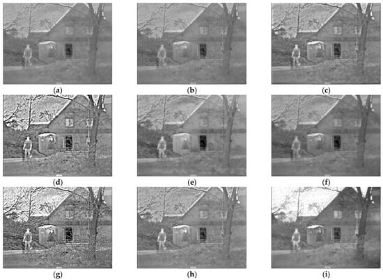
Figure 5.
Results on Data 1. (a) ICA; (b) ADKLT; (c) MFSD; (d) MDLatLRR; (e) PMGI; (f) RFNNest; (g) EgeFusion; (h) LEDIF; (i) Proposed.
Table 2.
The objective evaluation of different methods on Data 1.
From Table 2, it can be observed that our algorithm achieves optimal objective metrics on Data 1, with a value of 0.5860, value of 0.6029, value of 0.7047, value of 0.9248, value of 0.5838, value of 2.7156, value of 0.8067, value of 0.3908, value of 0.3280, and value of 0.8802.
Figure 6 displays the fusion results of various methods applied to Data 2, along with the corresponding metric data shown in Table 3. Observing the fusion results, it is evident that the ICA, ADKLT, and PMGI algorithms produced fused images that are blurred and exhibit low brightness. The MFSD, RFNNest, and LEDIF methods suffered from some loss of thermal radiation information. In contrast, the MDLatLRR and EgeFusion algorithms resulted in sharpened images, enhancing the human subjects but potentially causing distortion in other areas due to the sharpening effect. Our algorithm achieved the best fusion result.
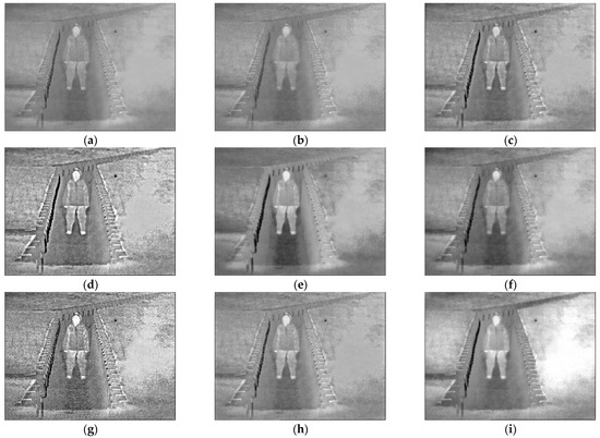
Figure 6.
Results on Data 2. (a) ICA; (b) ADKLT; (c) MFSD; (d) MDLatLRR; (e) PMGI; (f) RFNNest; (g) EgeFusion; (h) LEDIF; (i) Proposed.
Table 3.
The objective evaluation of different methods on Data 2.
From Table 3, it is apparent that our algorithm achieved superior objective metrics on Data 2, with a value of 0.6880, value of 0.6771, value of 0.7431, value of 0.9623, value of 0.6860, value of 3.6399, value of 0.8112, value of 0.5043, value of 0.2976, and value of 0.9458.
Figure 7 depicts the fusion results of various methods applied to Data 3, accompanied by the corresponding metric data shown in Table 4. Analyzing the fusion outcomes, it is evident that the ICA and ADKLT algorithms produced blurry fused images with significant loss of information. The MFSD method introduced artifacts in certain regions. While the MDLatLRR and EgeFusion algorithms increased the overall brightness, they also introduced artifacts. The PMGI and RFNNest algorithms resulted in distorted fused images. The LEDIF algorithm achieved commendable fusion results, albeit with some artifacts present. Our algorithm yielded the best fusion result, achieving moderate brightness and preserving the thermal radiation characteristics.
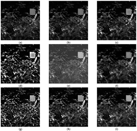
Figure 7.
Results on Data 3. (a) ICA; (b) ADKLT; (c) MFSD; (d) MDLatLRR; (e) PMGI; (f) RFNNest; (g) EgeFusion; (h) LEDIF; (i) Proposed.
Table 4.
The objective evaluation of different methods on Data 3.
From Table 4, it is apparent that our algorithm attained optimal objective metrics on Data 3, with a value of 0.7252, value of 0.6830, value of 0.8105, value of 0.8887, value of 0.7182, value of 4.4156, value of 0.8131, value of 0.6674, value of 0.8141, and value of 0.9395.
Figure 8 displays the fusion results of various methods applied to Data 4, alongside the corresponding metric data shown in Table 5. Upon reviewing the fusion outcomes, it is evident that the fusion images produced by the ICA, ADKLT, MFSD, PMGI, and LEDIF algorithms exhibit some loss of brightness information. The MDLatLRR and EgeFusion algorithms sharpened the fused image, while the RFNNest method resulted in a darker fused image with some information loss. In contrast, our algorithm produced a fused image with complementary information.
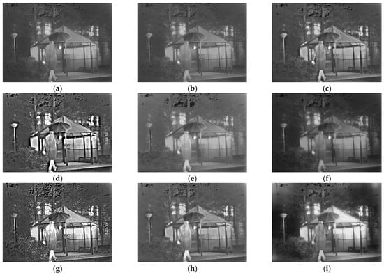
Figure 8.
Results on Data 4. (a) ICA; (b) ADKLT; (c) MFSD; (d) MDLatLRR; (e) PMGI; (f) RFNNest; (g) EgeFusion; (h) LEDIF; (i) Proposed.
Table 5.
The objective evaluation of different methods on Data 4.
From Table 5, it is notable that our algorithm achieved optimal objective metrics on Data 4, with a value of 0.5947, value of 0.5076, value of 0.6975, value of 0.9059, value of 0.5915, value of 2.5337, value of 0.8062, value of 0.3571, value of 0.5059, and value of 0.8553.
Figure 9 provides detailed insights into the objective performance of the various fusion methods across 42 pairs of data from the TNO dataset. The horizontal axis represents the number of data pairs used in our experiments, while the vertical axis represents the metric values. Each method’s scores across different source images are plotted as curves, with the average score indicated in the legend. Figure 9 illustrates that most methods show consistent trends across the metrics examined, and nearly all fusion methods demonstrate stable performance across all test images, with few exceptions. Therefore, comparisons based on average values in Table 6 hold significant value.
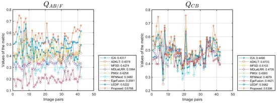
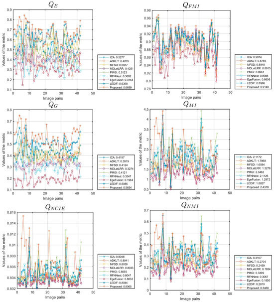
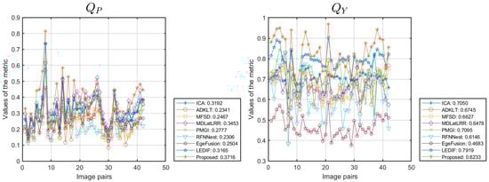
Figure 9.
Objective performance of different methods on the TNO dataset.
Table 6.
The average objective evaluation of the different methods on 42 pairs of data from the TNO dataset.
5.4. Experimental Expansion
We expanded our proposed algorithm to include the fusion of multi-focus images from the Lytro [70] and MFI-WHU datasets [71], selecting 20 and 30 groups of data for testing, respectively. The simulation results for one of the data groups are shown in Figure 10. This extension involved a comparative evaluation against eight methods: ICA [50], FusionDN [72], PMGI [54], U2Fusion [73], LEGFF [74], ZMFF [75], EgeFusion [56], and LEDIF [57]. The assessment utilized both subjective visual inspection and objective metrics. Figure 11 and Figure 12 provide detailed insights into the objective performance of various fusion methods on the Lytro and MFI-WHU datasets, with the corresponding average metric values shown in Table 7 and Table 8. From the results in Figure 10, it is evident that the ICA and PMGI algorithms tended to produce fused images with noticeable blurriness, impacting the clarity of detailed information within the fused images. The fused images produced by the FusionDN and U2Fusion algorithms exhibited dark regions in specific areas, such as hair regions in portraits, which detracted from overall visual quality. The fusion results of the LEGFF, ZMFF, and LEDIF algorithms are quite similar, all achieving fully focused fusion effects. The fused image generated by the EgeFusion algorithm showed distortions that made it challenging to discern detailed parts of the image. Our algorithm demonstrated promising results both visually and quantitatively when compared with the other algorithms. Subjective visual assessment indicated that our method effectively enhanced the presentation of complementary information in the fused images, preserving clarity and detail across different focus levels.
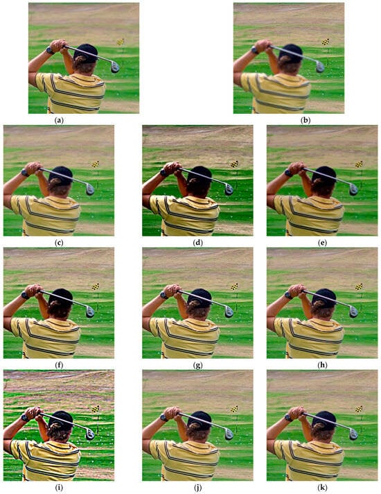
Figure 10.
Results on Lytro-01. (a) Near focus; (b) Far focus; (c) ICA; (d) FusionDN; (e) PMGI; (f) U2Fusion; (g) LEGFF; (h) ZMFF; (i) EgeFusion; (j) LEDIF; (k) Proposed.
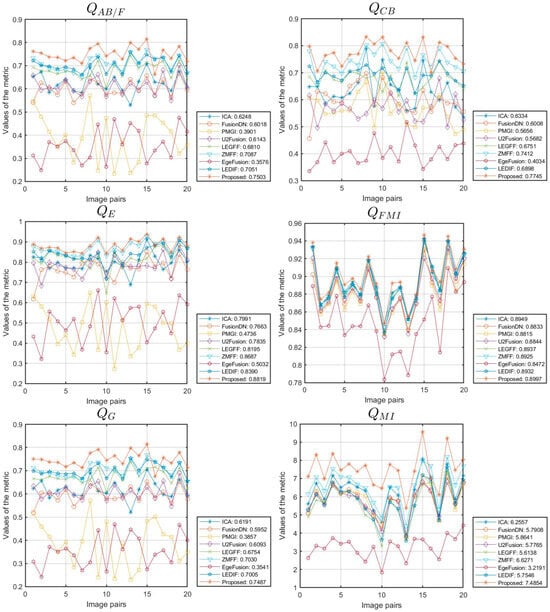
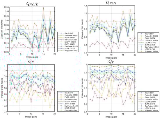
Figure 11.
Objective performance of different methods on the Lytro dataset.
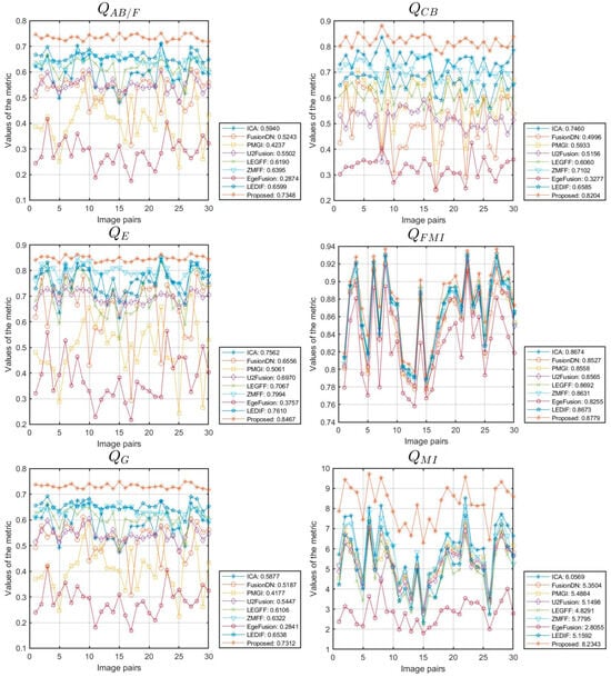
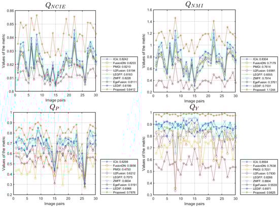
Figure 12.
Objective performance of different methods on the MFI-WHU dataset.
Table 7.
The average objective evaluation of different methods on 20 pairs of data from the Lytro dataset.
Table 8.
The average objective evaluation of different methods on 30 pairs of data from the MFI-WHU dataset.
6. Conclusions
To enhance the clarity and thermal radiation fidelity of infrared and visible image fusion, a fusion method based on sparse representation and guided filtering in the Laplacian pyramid domain is introduced. The Laplacian pyramid serves as an efficient multi-scale transform that decomposes the original image into distinct low- and high-frequency components. Low-frequency bands, crucial for capturing overall scene structure and thermal characteristics, are processed using the sparse representation technique. Sparse representation ensures that key features are preserved while reducing noise and maintaining thermal radiation attributes. High-frequency bands, which encompass fine details and textures vital for visual clarity, are enhanced using guided filtering integrated with WSEML. This approach successfully combines the contextual details from the source images, ensuring that the fused output maintains sharpness and fidelity across different scales. We carried out thorough simulation tests using the well-known TNO dataset to assess the performance of our algorithm. The results demonstrate that our method successfully preserves thermal radiation characteristics while enhancing scene details in the fused images. By continuing to innovate within the framework of sparse representation and guided filtering in the Laplacian pyramid domain, we aim to contribute significantly to the advancement of image fusion techniques, particularly in scenarios where preserving thermal characteristics and enhancing visual clarity are paramount. Moreover, we extended our approach to conducting fusion experiments on multi-focus images, achieving satisfactory results in capturing diverse focal points within a single fused output.
In our future research, we plan to further refine and expand our algorithm’s capabilities. Specifically, we aim to explore enhancements tailored for the fusion of synthetic aperture radar (SAR) and optical images [76]. By integrating SAR data, which provide unique insights into surface properties and structures, with optical imagery, which offers high-resolution contextual information, we anticipate developing a robust fusion framework capable of addressing diverse application scenarios effectively. Additionally, research on change detection based on fusion models is also one of our future research directions [77,78,79,80].
Author Contributions
The experimental measurements and data collection were carried out by L.L., Y.S., M.L. (Ming Lv), Z.J., M.L. (Minqin Liu), X.Z. (Xiaobin Zhao), X.Z. (Xueyu Zhang), and H.M. The manuscript was written by L.L. with the assistance of Y.S., M.L. (Ming Lv), Z.J., M.L. (Minqin Liu), X.Z. (Xiaobin Zhao), X.Z. (Xueyu Zhang), and H.M. All authors have read and agreed to the published version of the manuscript.
Funding
This work was supported by the National Natural Science Foundation of China under Grant Nos. 92152109 and 62261053; the Technology Innovation Program of Beijing Institute of Technology under Grant No. 2024CX02065; the Cross-Media Intelligent Technology Project of Beijing National Research Center for Information Science and Technology (BNRist) under Grant No. BNR2019TD01022; and the Tianshan Talent Training Project-Xinjiang Science and Technology Innovation Team Program (2023TSYCTD0012).
Data Availability Statement
The TNO dataset can be accessed via the following link: https://figshare.com/articles/dataset/TNO_Image_Fusion_Dataset/1008029 (accessed on 2 July 2024).
Conflicts of Interest
The authors declare no conflicts of interest.
References
- Liu, Y.; Liu, S.; Wang, Z. A general framework for image fusion based on multi-scale transform and sparse representation. Inf. Fusion 2015, 24, 147–164. [Google Scholar] [CrossRef]
- Huo, X.; Deng, Y.; Shao, K. Infrared and visible image fusion with significant target enhancement. Entropy 2022, 24, 1633. [Google Scholar] [CrossRef]
- Luo, Y.; Luo, Z. Infrared and visible image fusion: Methods, datasets, applications, and prospects. Appl. Sci. 2023, 13, 10891. [Google Scholar] [CrossRef]
- Li, L.; Lv, M.; Jia, Z.; Jin, Q.; Liu, M.; Chen, L.; Ma, H. An effective infrared and visible image fusion approach via rolling guidance filtering and gradient saliency map. Remote Sens. 2023, 15, 2486. [Google Scholar] [CrossRef]
- Ma, X.; Li, T.; Deng, J. Infrared and visible image fusion algorithm based on double-domain transform filter and contrast transform feature extraction. Sensors 2024, 24, 3949. [Google Scholar] [CrossRef]
- Wang, Q.; Yan, X.; Xie, W.; Wang, Y. Image fusion method based on snake visual imaging mechanism and PCNN. Sensors 2024, 24, 3077. [Google Scholar] [CrossRef]
- Feng, B.; Ai, C.; Zhang, H. Fusion of infrared and visible light images based on improved adaptive dual-channel pulse coupled neural network. Electronics 2024, 13, 2337. [Google Scholar] [CrossRef]
- Yang, H.; Zhang, J.; Zhang, X. Injected infrared and visible image fusion via L1 decomposition model and guided filtering. IEEE Trans. Comput. Imaging 2022, 8, 162–173. [Google Scholar]
- Zhang, X.; Boutat, D.; Liu, D. Applications of fractional operator in image processing and stability of control systems. Fractal Fract. 2023, 7, 359. [Google Scholar] [CrossRef]
- Zhang, X.; He, H.; Zhang, J. Multi-focus image fusion based on fractional order differentiation and closed image matting. ISA Trans. 2022, 129, 703–714. [Google Scholar] [CrossRef]
- Zhang, X.; Yan, H. Medical image fusion and noise suppression with fractional-order total variation and multi-scale decomposition. IET Image Process. 2021, 15, 1688–1701. [Google Scholar] [CrossRef]
- Yan, H.; Zhang, X. Adaptive fractional multi-scale edge-preserving decomposition and saliency detection fusion algorithm. ISA Trans. 2020, 107, 160–172. [Google Scholar] [CrossRef] [PubMed]
- Zhang, X.; Yan, H.; He, H. Multi-focus image fusion based on fractional-order derivative and intuitionistic fuzzy sets. Front. Inf. Technol. Electron. Eng. 2020, 21, 834–843. [Google Scholar] [CrossRef]
- Zhang, J.; Ding, J.; Chai, T. Fault-tolerant prescribed performance control of wheeled mobile robots: A mixed-gain adaption approach. IEEE Trans. Autom. Control 2024, 69, 5500–5507. [Google Scholar] [CrossRef]
- Zhang, J.; Xu, K.; Wang, Q. Prescribed performance tracking control of time-delay nonlinear systems with output constraints. IEEE/CAA J. Autom. Sin. 2024, 11, 1557–1565. [Google Scholar] [CrossRef]
- Wu, D.; Wang, Y.; Wang, H.; Wang, F.; Gao, G. DCFNet: Infrared and visible image fusion network based on discrete wavelet transform and convolutional neural network. Sensors 2024, 24, 4065. [Google Scholar] [CrossRef]
- Wei, Q.; Liu, Y.; Jiang, X.; Zhang, B.; Su, Q.; Yu, M. DDFNet-A: Attention-based dual-branch feature decomposition fusion network for infrared and visible image fusion. Remote Sens. 2024, 16, 1795. [Google Scholar] [CrossRef]
- Li, X.; He, H.; Shi, J. HDCCT: Hybrid densely connected CNN and transformer for infrared and visible image fusion. Electronics 2024, 13, 3470. [Google Scholar] [CrossRef]
- Mao, Q.; Zhai, W.; Lei, X.; Wang, Z.; Liang, Y. CT and MRI image fusion via coupled feature-learning GAN. Electronics 2024, 13, 3491. [Google Scholar] [CrossRef]
- Wang, Z.; Chen, Y.; Shao, W. SwinFuse: A residual swin transformer fusion network for infrared and visible images. IEEE Trans. Instrum. Meas. 2023, 71, 5016412. [Google Scholar] [CrossRef]
- Ma, J.; Tang, L.; Fan, F. SwinFusion: Cross-domain long-range learning for general image fusion via swin transformer. IEEE-CAA J. Autom. Sin. 2022, 9, 1200–1217. [Google Scholar] [CrossRef]
- Gao, F.; Lang, P.; Yeh, C.; Li, Z.; Ren, D.; Yang, J. An interpretable target-aware vision transformer for polarimetric HRRP target recognition with a novel attention loss. Remote Sens. 2024, 16, 3135. [Google Scholar] [CrossRef]
- Huang, L.; Chen, Y.; He, X. Spectral-spatial Mamba for hyperspectral image classification. Remote Sens. 2024, 16, 2449. [Google Scholar] [CrossRef]
- Zhang, X.; Demiris, Y. Visible and infrared image fusion using deep learning. IEEE Trans. Pattern Anal. Mach. Intell. 2023, 45, 10535–10554. [Google Scholar] [CrossRef]
- Zhang, X.; Ye, P.; Xiao, G. VIFB: A visible and infrared image fusion benchmark. In Proceedings of the IEEE/CVF Conference on Computer Vision and Pattern Recognition Workshops, Seattle, WA, USA, 14–19 June 2020. [Google Scholar]
- Li, H.; Wu, X. CrossFuse: A novel cross attention mechanism based infrared and visible image fusion approach. Inf. Fusion 2024, 103, 102147. [Google Scholar] [CrossRef]
- Liu, Y.; Chen, X.; Wang, Z. Deep learning for pixel-level image fusion: Recent advances and future prospects. Inf. Fusion 2018, 42, 158–173. [Google Scholar] [CrossRef]
- Liu, Y.; Chen, X.; Cheng, J. Infrared and visible image fusion with convolutional neural networks. Int. J. Wavelets Multiresolut. Inf. Process. 2018, 16, 1850018. [Google Scholar] [CrossRef]
- Yang, C.; He, Y. Multi-scale convolutional neural networks and saliency weight maps for infrared and visible image fusion. J. Vis. Commun. Image Represent. 2024, 98, 104015. [Google Scholar] [CrossRef]
- Wei, H.; Fu, X.; Wang, Z.; Zhao, J. Infrared/Visible light fire image fusion method based on generative adversarial network of wavelet-guided pooling vision transformer. Forests 2024, 15, 976. [Google Scholar] [CrossRef]
- Ma, J.; Xu, H. DDcGAN: A dual-discriminator conditional generative adversarial network for multi-resolution image fusion. IEEE Trans. Image Process. 2020, 29, 4980–4995. [Google Scholar] [CrossRef]
- Chang, L.; Huang, Y. DUGAN: Infrared and visible image fusion based on dual fusion paths and a U-type discriminator. Neurocomputing 2024, 578, 127391. [Google Scholar] [CrossRef]
- Lv, M.; Jia, Z.; Li, L.; Ma, H. Multi-focus image fusion via PAPCNN and fractal dimension in NSST domain. Mathematics 2023, 11, 3803. [Google Scholar] [CrossRef]
- Lv, M.; Li, L.; Jin, Q.; Jia, Z.; Chen, L.; Ma, H. Multi-focus image fusion via distance-weighted regional energy and structure tensor in NSCT domain. Sensors 2023, 23, 6135. [Google Scholar] [CrossRef]
- Li, L.; Lv, M.; Jia, Z.; Ma, H. Sparse representation-based multi-focus image fusion method via local energy in shearlet domain. Sensors 2023, 23, 2888. [Google Scholar] [CrossRef]
- Ma, J.; Ma, Y.; Li, C. Infrared and visible image fusion methods and applications: A survey. Inf. Fusion 2019, 45, 153–178. [Google Scholar] [CrossRef]
- Liu, Y.; Wang, L.; Cheng, J. Multi-focus image fusion: A survey of the state of the art. Inf. Fusion 2020, 64, 71–91. [Google Scholar] [CrossRef]
- Chen, H.; Deng, L. SFCFusion: Spatial-frequency collaborative infrared and visible image fusion. IEEE Trans. Instrum. Meas. 2024, 73, 5011615. [Google Scholar] [CrossRef]
- Chen, H.; Deng, L.; Zhu, L.; Dong, M. ECFuse: Edge-consistent and correlation-driven fusion framework for infrared and visible image fusion. Sensors 2023, 23, 8071. [Google Scholar] [CrossRef]
- Li, X.; Tan, H. Infrared and visible image fusion based on domain transform filtering and sparse representation. Infrared Phys. Technol. 2023, 131, 104701. [Google Scholar] [CrossRef]
- Chen, Y.; Liu, Y. Multi-focus image fusion with complex sparse representation. IEEE Sens. J. 2024; early access. [Google Scholar]
- Li, S.; Kwok, J.T.; Wang, Y. Multifocus image fusion using artificial neural networks. Pattern Recognit. Lett. 2002, 23, 985–997. [Google Scholar] [CrossRef]
- Chang, C.I.; Liang, C.C.; Hu, P.F. Iterative Gaussian–Laplacian pyramid network for hyperspectral image classification. IEEE Trans. Geosci. Remote Sens. 2024, 62, 5510122. [Google Scholar] [CrossRef]
- Burt, P.J.; Adelson, E.H. The laplacian pyramid as a compact image code. IEEE Trans. Commun. 1983, 31, 532–540. [Google Scholar] [CrossRef]
- Chen, J.; Li, X.; Luo, L. Infrared and visible image fusion based on target-enhanced multiscale transform decomposition. Inf. Sci. 2020, 508, 64–78. [Google Scholar] [CrossRef]
- Yin, M.; Liu, X.; Liu, Y. Medical image fusion with parameter-adaptive pulse coupled neural network in nonsubsampled shearlet transform domain. IEEE Trans. Instrum. Meas. 2019, 68, 49–64. [Google Scholar] [CrossRef]
- He, K.; Sun, J.; Tang, X. Guided image filtering. IEEE Trans. Pattern Anal. Mach. Intell. 2013, 35, 1397–1409. [Google Scholar] [CrossRef]
- Li, S.; Kang, X.; Hu, J. Image fusion with guided filtering. IEEE Trans. Image Process. 2013, 22, 2864–2875. [Google Scholar]
- Available online: https://figshare.com/articles/dataset/TNO_Image_Fusion_Dataset/1008029 (accessed on 1 May 2024).
- Mitianoudis, N.; Stathaki, T. Pixel-based and region-based image fusion schemes using ICA bases. Inf. Fusion 2007, 8, 131–142. [Google Scholar] [CrossRef]
- Bavirisetti, D.P.; Dhuli, R. Fusion of infrared and visible sensor images based on anisotropic diffusion and Karhunen-Loeve transform. IEEE Sens. J. 2016, 16, 203–209. [Google Scholar] [CrossRef]
- Bavirisetti, D.P.; Dhuli, R. Two-scale image fusion of visible and infrared images using saliency detection. Infrared Phys. Technol. 2016, 76, 52–64. [Google Scholar] [CrossRef]
- Li, H.; Wu, X.; Kittler, J. MDLatLRR: A novel decomposition method for infrared and visible image fusion. IEEE Trans. Image Process. 2020, 29, 4733–4746. [Google Scholar] [CrossRef]
- Zhang, H.; Xu, H.; Xiao, Y. Rethinking the image fusion: A fast unified image fusion network based on proportional maintenance of gradient and intensity. In Proceedings of the AAAI Conference on Artificial Intelligence, New York, NY, USA, 7–12 February 2020; Volume 34, pp. 12797–12804. [Google Scholar]
- Li, H.; Wu, X.; Kittler, J. RFN-Nest: An end-to-end residual fusion network for infrared and visible images. Inf. Fusion 2021, 73, 72–86. [Google Scholar] [CrossRef]
- Tang, H.; Liu, G. EgeFusion: Towards edge gradient enhancement in infrared and visible image fusion with multi-scale transform. IEEE Trans. Comput. Imaging 2024, 10, 385–398. [Google Scholar] [CrossRef]
- Xiang, W.; Shen, J.; Zhang, L.; Zhang, Y. Infrared and visual image fusion based on a local-extrema-driven image filter. Sensors 2024, 24, 2271. [Google Scholar] [CrossRef] [PubMed]
- Qu, X.; Yan, J.; Xiao, H. Image fusion algorithm based on spatial frequency-motivated pulse coupled neural networks in nonsubsampled contourlet transform domain. Acta Autom. Sin. 2008, 34, 1508–1514. [Google Scholar] [CrossRef]
- Li, S.; Han, M.; Qin, Y.; Li, Q. Self-attention progressive network for infrared and visible image fusion. Remote Sens. 2024, 16, 3370. [Google Scholar] [CrossRef]
- Li, L.; Zhao, X.; Hou, H.; Zhang, X.; Lv, M.; Jia, Z.; Ma, H. Fractal dimension-based multi-focus image fusion via coupled neural P systems in NSCT domain. Fractal Fract. 2024, 8, 554. [Google Scholar] [CrossRef]
- Zhai, H.; Ouyang, Y.; Luo, N. MSI-DTrans: A multi-focus image fusion using multilayer semantic interaction and dynamic transformer. Displays 2024, 85, 102837. [Google Scholar] [CrossRef]
- Li, L.; Ma, H.; Jia, Z.; Si, Y. A novel multiscale transform decomposition based multi-focus image fusion framework. Multimed. Tools Appl. 2021, 80, 12389–12409. [Google Scholar] [CrossRef]
- Li, B.; Zhang, L.; Liu, J.; Peng, H. Multi-focus image fusion with parameter adaptive dual channel dynamic threshold neural P systems. Neural Netw. 2024, 179, 106603. [Google Scholar] [CrossRef]
- Liu, Z.; Blasch, E.; Xue, Z. Objective assessment of multiresolution image fusion algorithms for context enhancement in night vision: A comparative study. IEEE Trans. Pattern Anal. Mach. Intell. 2012, 34, 94–109. [Google Scholar] [CrossRef]
- Zhai, H.; Chen, Y.; Wang, Y. W-shaped network combined with dual transformers and edge protection for multi-focus image fusion. Image Vis. Comput. 2024, 150, 105210. [Google Scholar] [CrossRef]
- Haghighat, M.; Razian, M. Fast-FMI: Non-reference image fusion metric. In Proceedings of the IEEE 8th International Conference on Application of Information and Communication Technologies, Astana, Kazakhstan, 15–17 October 2014; pp. 424–426. [Google Scholar]
- Wang, X.; Fang, L.; Zhao, J.; Pan, Z.; Li, H.; Li, Y. MMAE: A universal image fusion method via mask attention mechanism. Pattern Recognit. 2025, 158, 111041. [Google Scholar] [CrossRef]
- Zhang, X.; Li, W. Hyperspectral pathology image classification using dimension-driven multi-path attention residual network. Expert Syst. Appl. 2023, 230, 120615. [Google Scholar] [CrossRef]
- Zhang, X.; Li, Q. FD-Net: Feature distillation network for oral squamous cell carcinoma lymph node segmentation in hyperspectral imagery. IEEE J. Biomed. Health Inform. 2024, 28, 1552–1563. [Google Scholar] [CrossRef]
- Nejati, M.; Samavi, S.; Shirani, S. Multi-focus image fusion using dictionary-based sparse representation. Inf. Fusion 2015, 25, 72–84. [Google Scholar] [CrossRef]
- Zhang, H.; Le, Z. MFF-GAN: An unsupervised generative adversarial network with adaptive and gradient joint constraints for multi-focus image fusion. Inf. Fusion 2021, 66, 40–53. [Google Scholar] [CrossRef]
- Xu, H.; Ma, J.; Le, Z. FusionDN: A unified densely connected network for image fusion. In Proceedings of the Thirty-Fourth AAAI Conference on Artificial Intelligence (AAAI), New York, NY, USA, 7–12 February 2020; Volume 34, pp. 12484–12491. [Google Scholar]
- Xu, H.; Ma, J.; Jiang, J. U2Fusion: A unified unsupervised image fusion network. IEEE Trans. Pattern Anal. Mach. Intell. 2022, 44, 502–518. [Google Scholar] [CrossRef]
- Zhang, Y.; Xiang, W. Local extreme map guided multi-modal brain image fusion. Front. Neurosci. 2022, 16, 1055451. [Google Scholar] [CrossRef]
- Hu, X.; Jiang, J.; Liu, X.; Ma, J. ZMFF: Zero-shot multi-focus image fusion. Inf. Fusion 2023, 92, 127–138. [Google Scholar] [CrossRef]
- Li, J.; Zhang, J.; Yang, C.; Liu, H.; Zhao, Y.; Ye, Y. Comparative analysis of pixel-level fusion algorithms and a new high-resolution dataset for SAR and optical image fusion. Remote Sens. 2023, 15, 5514. [Google Scholar] [CrossRef]
- Li, L.; Ma, H.; Jia, Z. Multiscale geometric analysis fusion-based unsupervised change detection in remote sensing images via FLICM model. Entropy 2022, 24, 291. [Google Scholar] [CrossRef] [PubMed]
- Li, L.; Ma, H.; Zhang, X.; Zhao, X.; Lv, M.; Jia, Z. Synthetic aperture radar image change detection based on principal component analysis and two-level clustering. Remote Sens. 2024, 16, 1861. [Google Scholar] [CrossRef]
- Li, L.; Ma, H.; Jia, Z. Change detection from SAR images based on convolutional neural networks guided by saliency enhancement. Remote Sens. 2021, 13, 3697. [Google Scholar] [CrossRef]
- Li, L.; Ma, H.; Jia, Z. Gamma correction-based automatic unsupervised change detection in SAR images via FLICM model. J. Indian Soc. Remote Sens. 2023, 51, 1077–1088. [Google Scholar] [CrossRef]
Disclaimer/Publisher’s Note: The statements, opinions and data contained in all publications are solely those of the individual author(s) and contributor(s) and not of MDPI and/or the editor(s). MDPI and/or the editor(s) disclaim responsibility for any injury to people or property resulting from any ideas, methods, instructions or products referred to in the content. |
© 2024 by the authors. Licensee MDPI, Basel, Switzerland. This article is an open access article distributed under the terms and conditions of the Creative Commons Attribution (CC BY) license (https://creativecommons.org/licenses/by/4.0/).