Article

Seismic Imaging of the Arctic Subsea Permafrost Using a Least-Squares Reverse Time Migration Method

1
Department of Energy & Resources Engineering, National Korea Maritime and Ocean University, Busan 49112, Republic of Korea
2
Division of Glacier & Earth Sciences, Korea Polar Research Institute, Incheon 21990, Republic of Korea
3
Digital and Integration, Schlumberger, Tokyo 103-0027, Japan
*
Author to whom correspondence should be addressed.
Remote Sens. 2024, 16(18), 3425; https://doi.org/10.3390/rs16183425
Submission received: 14 August 2024 / Revised: 9 September 2024 / Accepted: 11 September 2024 / Published: 14 September 2024

Abstract

:
High-resolution seismic imaging allows for the better interpretation of subsurface geological structures. In this study, we employ least-squares reverse time migration (LSRTM) as a seismic imaging method to delineate the subsurface geological structures from the field dataset for understanding the status of Arctic subsea permafrost structures, which is pertinent to global warming issues. The subsea permafrost structures in the Arctic continental shelf, located just below the seafloor at a shallow water depth, have an abnormally high P-wave velocity. These structural conditions create internal multiples and noise in seismic data, making it challenging to perform seismic imaging and construct a seismic P-wave velocity model using conventional methods. LSRTM offers a promising approach by addressing these challenges through linearized inverse problems, aiming to achieve high-resolution, subsurface imaging by optimizing the misfit between the predicted and the observed seismic data. Synthetic experiments, encompassing various subsea permafrost structures and seismic survey configurations, were conducted to investigate the feasibility of LSRTM for imaging the Arctic subsea permafrost from the acquired seismic field dataset, and the possibility of the seismic imaging of the subsea permafrost was confirmed through these synthetic numerical experiments. Furthermore, we applied the LSRTM method to the seismic data acquired in the Canadian Beaufort Sea (CBS) and generated a seismic image depicting the subsea permafrost structures in the Arctic region.

1. Introduction

Seismic migration plays a crucial role in interpreting the Earth’s interior structure. It provides a subsurface image from the seismic data that represents the geological structures by collapsing diffraction and focusing seismic events onto their origin position. Generally, under the single scattering approximation, seismic migration is implemented based on the fundamental imaging principle, which states that the reflector exists where the source and receiver wavefields coincide spatiotemporally [1].
Our target for seismic imaging is the subsea permafrost in the Arctic continental shelf, formed when the sea level rose by at least 120 m since the Last Glacial Maximum (LGM), flooding the coastal permafrost [2]. The subsea permafrost structures were generally distributed in the continental shelf at shallow water depths less than 100 m and have abnormal geophysical parameters such as seismic P-wave velocities and density depending on the ice contents rather than surroundings. The subsea permafrost was known for acting as a methane gas reservoir and helping maintain the gas hydrate with its low-temperature condition [3,4]. As the subsea permafrost has been degraded by exposure to relatively warmer temperatures due to the retreat of the glaciers, many scientists have argued that its thawing leads to methane gas emission to the oceanic and atmospheric environment [5,6]. Hence, subsea permafrost has been studied intensively to determine its extent and reveal its influence on global warming issues [7].
Geophysical characteristics, especially the abnormal seismic P-wave velocity of the subsea permafrost, which consists of a large lump of ice with relatively high velocity, have been widely utilized to determine the extent of the subsea permafrost. Generally, subsea permafrost is found beneath the seafloor on a continental shelf where shallow water has a depth of less than 100 m. Due to a strong velocity contrast in these shallow regions, the refraction signal is recorded in the seismic dataset at an earlier travel time. Previous studies have exploited these refraction signals to estimate velocity information and define the extent of the subsea permafrost in the Arctic environment [8,9,10]. Additionally, various seismic signals, such as reflection, diffraction, and guided wave, can be used to determine the extent of the subsea permafrost by estimating the velocity variations [10,11,12,13,14,15]. Although studies with estimated velocity information can map the lateral extent of the subsea permafrost, their results have a low resolution in defining the vertical extent of the subsea permafrost.
In this study, we exploit the seismic migration method for high-resolution seismic imaging to investigate the status of the subsea permafrost. However, due to the single scattering approximation, the seismic migration operator behaves like the adjoint operator (or the Hermitian operator) for the single scattering forward modeling operator [16]. Under ideal data acquisition conditions (e.g., unlimited-bandwidth source wavelet, infinite geometry aperture, regular acquisition sampling, etc.), the migration operator can represent the pseudo-inverse operator of the single scattering forward modeling operator. However, these ideal conditions are rarely met in a seismic survey configuration in the Arctic. As a result, the migration operator may exhibit several inherent problems (e.g., migration artifacts, seismic amplitude imbalance) and degrade the migration quality by smearing the reflectivity. If the forward modeling operator is treated as linear, the migration scheme can be formulated to linearize the inverse problem.
This inversion-based migration scheme, known as least-squares migration (LSM), aims to minimize the disparity between predicted and observed data to produce high-quality migration images. Attenuating the migration artifacts and reflectivity amplitude recovery are also LSM achievements. Initially developed from the Kirchhoff migration engine, LSM has evolved with various modeling/migration engines based on the wave equation and ray theory, for instance, one-way migration [17,18] and Gaussian beam migration [19,20,21]. While LSM methods demonstrate computational efficiency in generating migration images, they are constrained in handling various wave phenomena with a high propagation angle. These methods rely on assumptions and limitations inherent in ray theory or one-way wave equations, particularly concerning propagation angles. Consequently, accurate migration images may be challenging when significant geological heterogeneities are present in the velocity model.
As an advanced LSM method, least-squares reverse time migration (LSRTM), based on the reverse time migration (RTM) engine, exploits the full wavefield solution of the two-way wave equation. LSRTM has been shown to produce high-quality migration images with highly enhanced resolution, attenuated migration artifacts, and more balanced amplitudes compared to conventional RTM algorithms [22,23,24,25,26]. Furthermore, LSRTM is superior in handling complex geological settings, such as sub-basalt and salt structures, due to its ability to manage reflectors at various dip angles without limitations. Despite its advantages, LSRTM is known for its high computational cost, which scales with the number of iterations required in its iterative scheme. However, advancements in computing technology and efficient LSRTM techniques [27,28] have made its practical application increasingly feasible.
We employ the LSRTM method to image the subsea permafrost structures distributed in the Arctic shelf. In this study, we first provide an overview of the theory and workflow of LSRTM. Next, we present synthetic experiments to demonstrate the feasibility of LSRTM for the seismic imaging of the Arctic subsea permafrost structures. Finally, we apply LSRTM to a field dataset acquired from the Canadian Beaufort Sea in the Arctic Ocean to detect the structures of the subsea permafrost in the seismic image. This represents the first attempt to use a migration algorithm for seismic imaging of the subsea permafrost. We expect that advanced seismic imaging methods like LSRTM offer more detailed observations of the current status of the Arctic permafrost structures compared to other geophysical models.

2. Review of Least-Squares Reverse Time Migration

In LSRTM, two primary modeling operators formulate the linear forward problem. The first is the Born modeling operator, which relies on the Born approximation and describes the relationship between first scattering data and model perturbations. The second is the Kirchhoff modeling operator, based on the Kirchhoff approximation, which links the first scattering data to the reflection coefficient or reflectivity, depending on the incident angle [29]. Due to the advantages of the Kirchhoff approximation such as better fitting the amplitude with high amplitudes, we adopted the Kirchhoff approximation in this research. This section focuses on the LSRTM method using the Kirchhoff approximation, covering key aspects such as linear forward modeling, adjoint modeling, and gradient operators. A detailed explanation of the LSRTM-based Born approximation and a comparison between the Born and Kirchhoff approximation can be found in the literature [30].
Regardless of which approximation is used for simulating predicted data, the inverse problem in LSRTM is typically defined by an L2-norm-based misfit function. This function quantifies the discrepancy between predicted and observed data to determine the optimal solution, which, in this case, is the reflectivity. The L2-norm-based misfit function for LSRTM is expressed as:
E = 1 2 L m d 2 2 ,
where L is a linearized modeling operator, m is the reflectivity model, and d represents the observed data. Two wavefield simulations are required to synthesize predicted data L m . First, forward modeling is performed using the background velocity model, which does not contain any high wavenumber perturbations or reflectors. This is followed by forward modeling based on the reflectivity model to obtain the first scattering data. The forward source wavefield modeling in the background velocity model is achieved by solving the acoustic wave equation with the background velocity model, which can be expressed as follows:
1 c 0 x 2 𝜕 2 𝜕 t 2 2 p 0 x , t ; x s = f t ; x s ,
where c 0 ( x ) is the background velocity model, 2 denotes the Laplacian operator, p 0 ( x , t ; x s ) is the forward source wavefield, and f ( t ; x s ) is the source function. After computing the forward source wavefield, the simulated data can be obtained by applying the Kirchhoff modeling operator with the reflectivity model. The predicted data based on the Kirchhoff approximation can be obtained using Equation (3):
1 c 0 x 2 𝜕 2 𝜕 t 2 2 δ p x , t ; x s = 2 c 0 ( x ) 𝜕 p 0 x , t ; x s 𝜕 t R ( x ) ,
where δ p ( x , t ; x s ) denotes the first scattering wavefield, and R x represents the stacked reflectivity model along the incident angle. Kirchhoff’s modeling typically uses reflection coefficients that depend on the incident angle. However, generating these angle-dependent reflectivity values is often computationally expensive because it requires constructing angle domain common image gather (ADCIG). Therefore, in this study, we use the stacked reflectivity image R ( x ) to simulate the first scattering data.
Since forward modeling is linearly related to reflectivity, we can derive the true solution to the inverse problem in Equation (1) by using the normal equation form, as follows:
m t r u e = L T L 1 L T d = L T L 1 m m i g ,
where m t r u e represents the true reflectivity model, and m m i g is defined as L T d . It is important to note that the Hessian operator L T L acts as a blurring operator on the true reflectivity m t r u e , which can degrade the quality of the subsurface image. To recover the true reflectivity model from the migration image, the inverse of the Hessian operator is needed. However, the challenge for computing the inverse of the Hessian operator is not limited to the intensive computation demand; the worse obstacle is that the Hessian matrix is usually ill-conditioned and does not have an inverse [31]. To address this issue, various LSRTM approaches have been developed that approximate Hessian rather than computing its exact inverse. These approaches include gradient-based optimization migration deblurring in both the data domain [32] and the image domain [33,34]. In this study, we use gradient-based optimization as our iterative scheme. The optimal solution for Equation (1) can be obtained by updating the reflectivity model iteratively, as expressed below:
m k + 1 = m k + α P k g k
where k is the iteration number, α is the scalar representing the step length, P represents the preconditioning operator (approximation of the inverse of Hessian), and g is the gradient vector. The gradient vector g is obtained by cross-correlating the adjoint wavefield with the forward source wavefield, as follows:
g x = 1 c 0 ( x ) 𝜕 2 p 0 x , t ; x s 𝜕 t 2 q x , t d t ,
where q ( x , t ) is the adjoint wavefield, which can be computed using the below equation:
1 c 0 x 2 𝜕 2 𝜕 t 2 2 q x , t ; x s = δ d ( x r , T t ; x s ) ,
where δ d ( x r , T t ; x s ) is the data residual between predicted data, δ p ( x r , t ; x s ) , and observed data, d ( x r , t ; x s ) ; T is the maximum recording time.
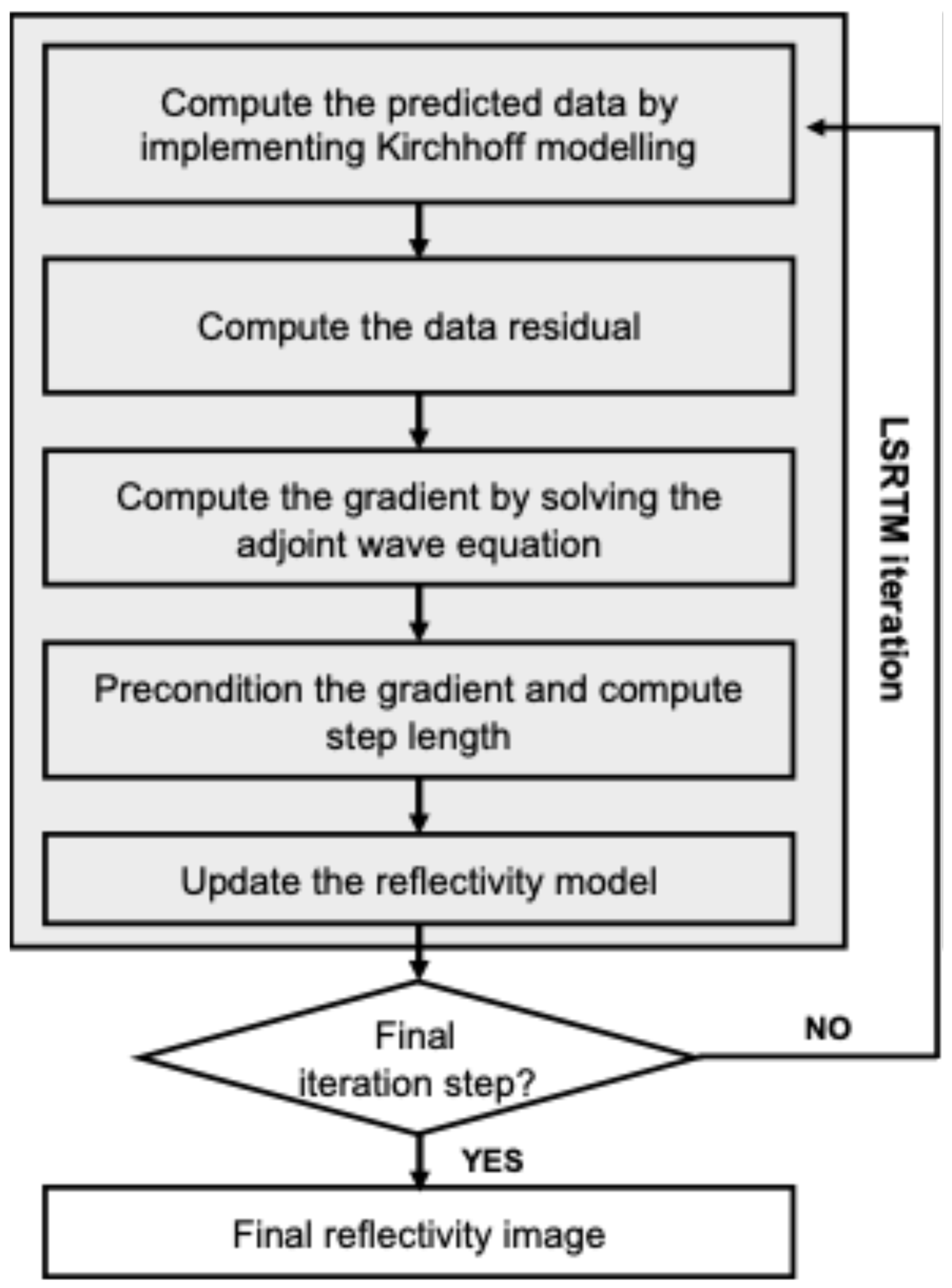
Figure 1 illustrates the LSRTM workflow. In LSRTM implementation, Kirchhoff modeling and the gradient operator use the forward source wavefield. Since storing the forward source wavefield for the full propagation time requires substantial memory, we use a source wavefield reconstruction scheme instead. This approach only constructs the forward source wavefield when the gradient vector is computed, thus reducing memory requirements [35].

3. Seismic Imaging of Synthetic Dataset

To evaluate the applicability of the LSRTM method for imaging the subsea permafrost using the acquired multi-channel seismic dataset, we first conduct a numerical test with a synthetic dataset. Two velocity models are used to simulate the subsea permafrost in the Arctic environment—a simple box and a realistic velocity model. All synthetic data were generated using a finite difference scheme with CPML boundary conditions [36] on four sides to avoid unwanted reflections from model boundaries. In this research, we assume that the observed dataset contains no multiple or noise. Thus, the observed dataset for LSRTM examples is generated by de-migration with the true reflectivity and background velocity models. In other words, our synthetic tests are an inverse crime to demonstrate the environment that is free for multiple reflection. The synthetic dataset was recorded by the streamer consisting of 120 channels of hydrophone, with a group interval of 12.5 m. The shot interval is 50 m, and the minimum offset is 87.5 m, respectively. The synthetic numerical test also assumes that the source wavelet is known. For LSRTM implementation, we use the preconditioned conjugate gradient method as the optimization technique, with ten iterations performed for all synthetic examples.

3.1. Simple Box Velocity Model

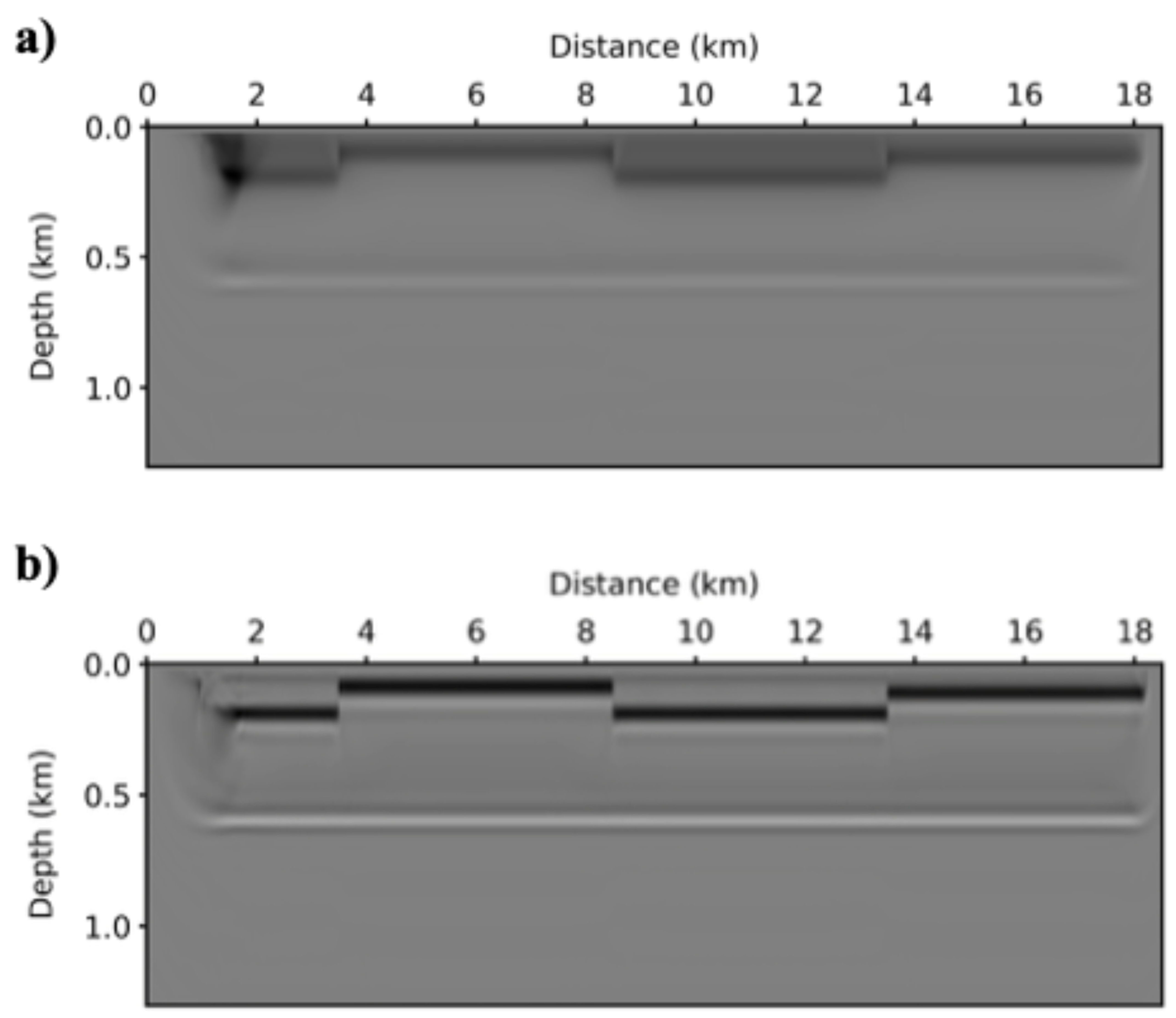
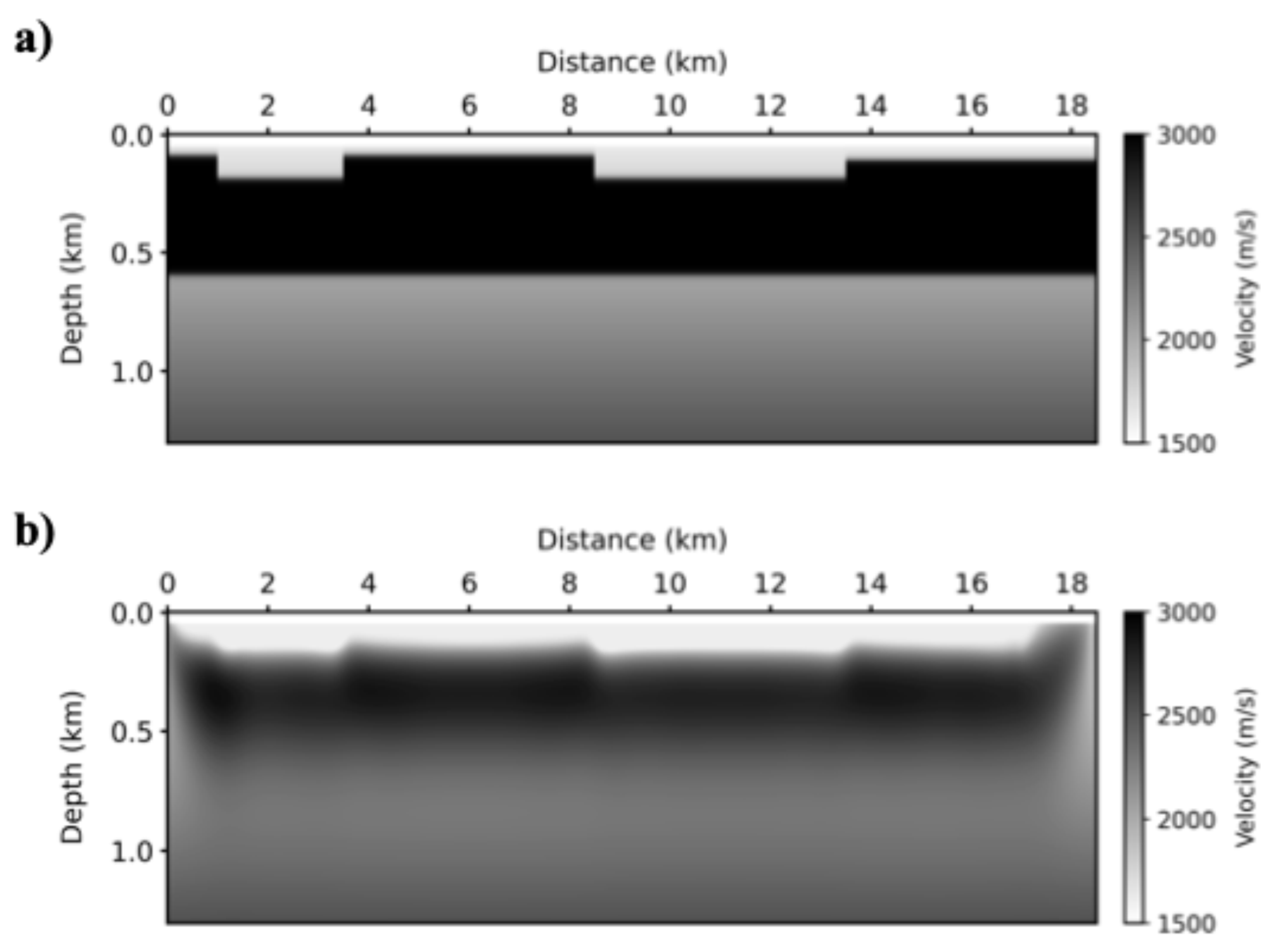
To demonstrate the feasibility of LSRTM for the seismic imaging of subsea permafrost on the Arctic continental shelf, we conducted a numerical test of LSRTM using a synthetic dataset. First, we used the simple box velocity model for generating the synthetic seismic dataset, as shown in Figure 2a. In this velocity model, the water depth is approximately 40 m, and the P-wave velocity of the subsea permafrost structure, located just below the seafloor, is 3000 m/s [37]. The velocity model is discretized by 2961 × 209 grids with 6.25 m horizontal and vertical grid intervals. In this test model, wave propagation modeling is performed to generate the synthetic dataset, and 330 shots are simulated with a 50 m shot interval from 1.75 km to 18.2 km. A 30 Hz centroid frequency Ricker wavelet is utilized as the source wavelet. The observed dataset is recorded for a duration of 2 s with a 1 ms sampling interval. The background velocity model, used as the background velocity for LSRTM, is generated by applying a 2D Gaussian filter in scipy module with a 75 m window length, as shown in Figure 2b.
Figure 3a shows the conventional RTM image, which captures the top boundary of the subsea permafrost but significantly dims the bottom boundary. This issue arises due to the amplitude imbalance caused by strong low-wavenumber artifacts from the pronounced velocity contrast of the subsea permafrost structure, making the bottom boundary difficult to discern. In contrast, Figure 3b presents an LSRTM image that provides a more precise depiction of the subsea permafrost’s top and bottom boundaries. LSRTM balances the amplitude and attenuates the strong low-wavenumber artifacts through iterative processing, resulting in sharper reflectors compared to the conventional RTM image. Although Laplace image filtering was not used in this study, it can also effectively balance amplitude and suppress strong low-wavenumber artifacts. Consequently, LSRTM substantially improves the quality and resolution of the migration images.
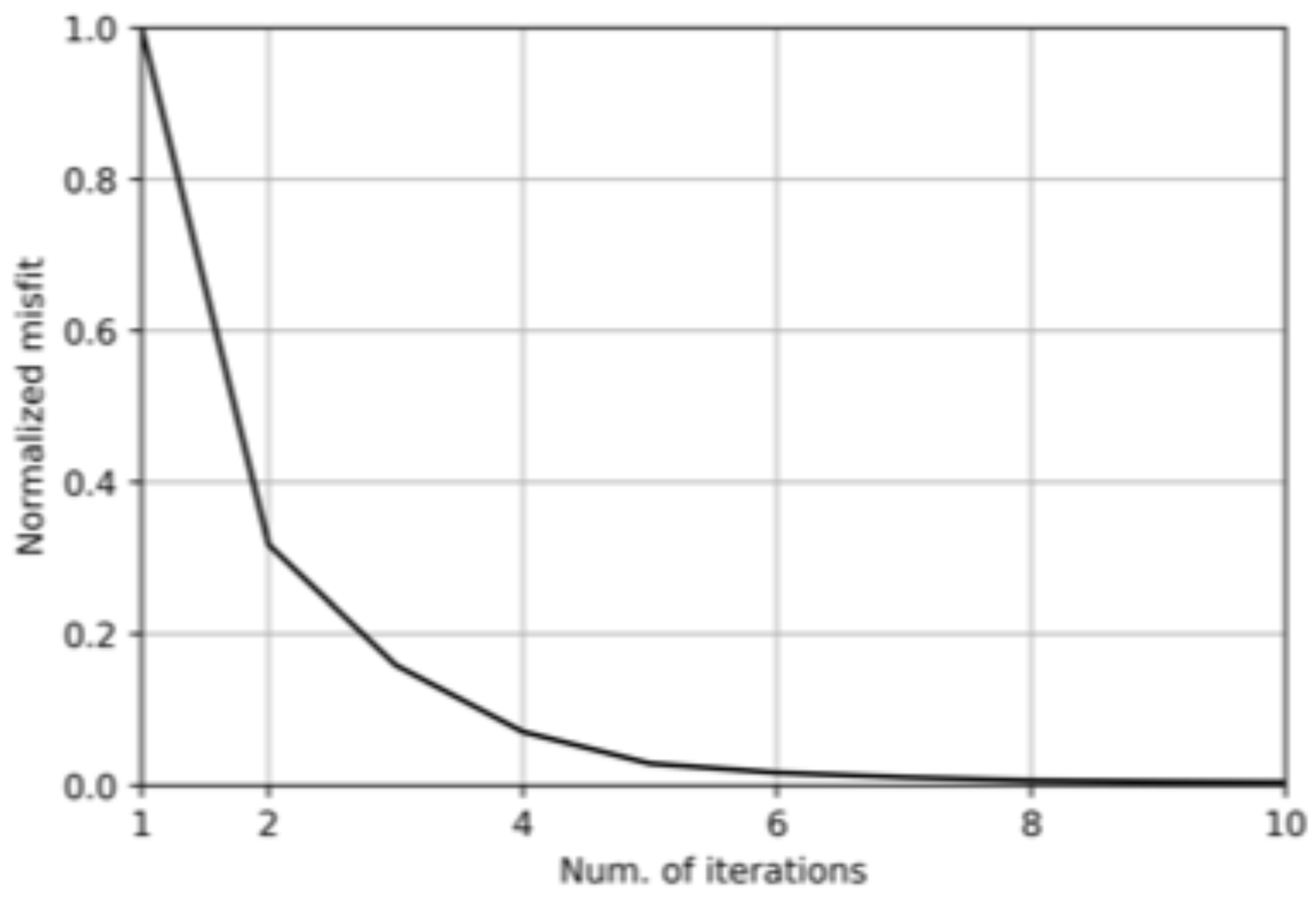
Figure 4 represents the normalized misfit history of the LSRTM for the simple velocity model. After the 10th iteration of LSRTM, the normalized misfit value reaches approximately 0.004. This misfit history indicates that LSRTM can provide a high-quality migration image with successful convergence.

3.2. Realistic Velocity Model for the Subsea Permafrost Structure

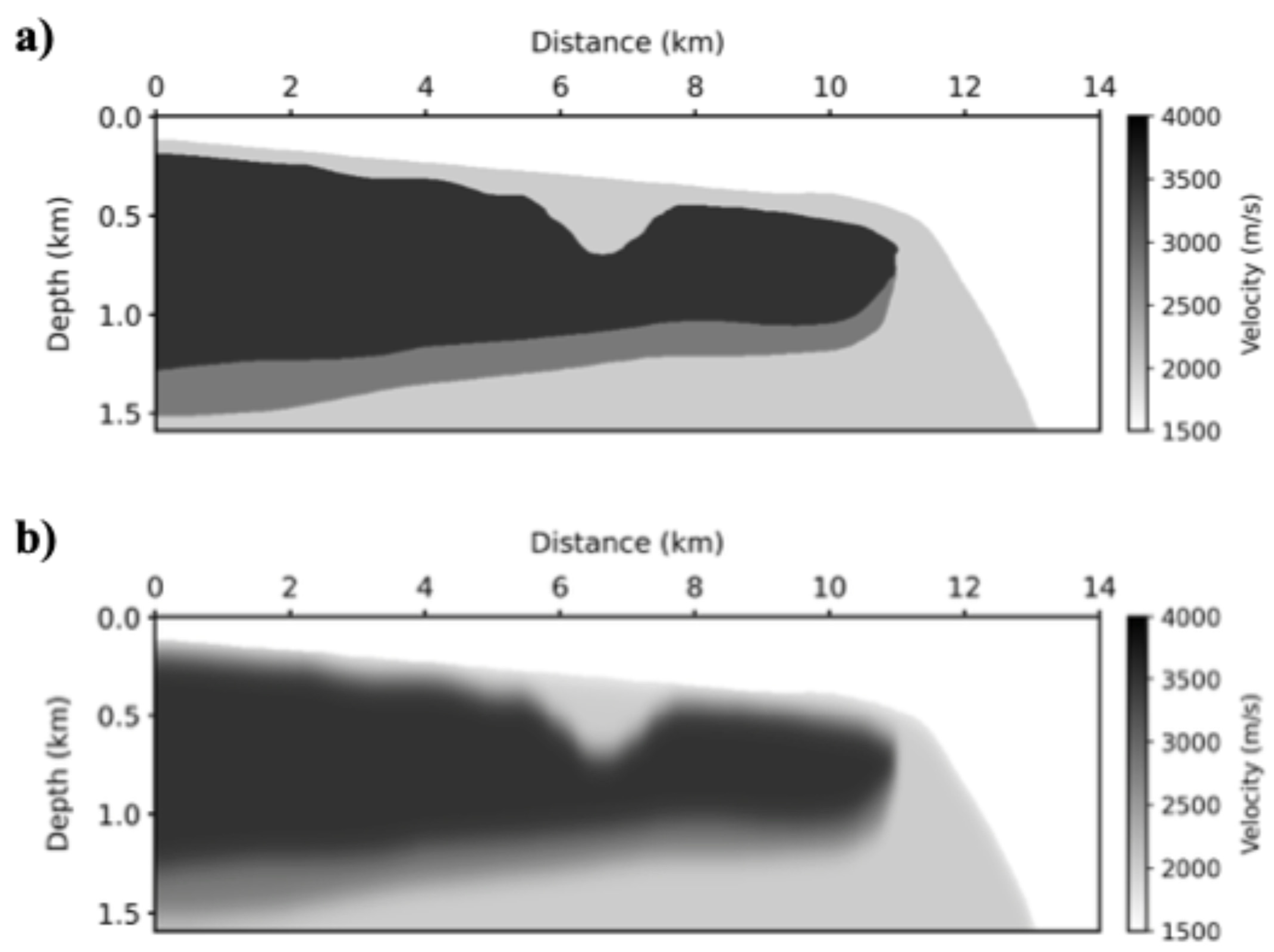
Next, we conducted another synthetic test using a realistic velocity model representing the Arctic subsea permafrost. The realistic permafrost velocity model is presented in Figure 5a. This velocity model illustrates fully and partially ice-bonded permafrost structures under the seafloor of the Arctic continental shelf, which have 3500 m/s and 2800 m/s of P-wave velocities, respectively [38]. This velocity model is discretized by 2241 × 255 with a 6.25 m grid size. We also perform wave propagation modeling for this numerical test, generating 240 observed datasets from evenly deployed shots with 50 m shot intervals from 1.75 km to 13.7 km. A 50 Hz Ricker wavelet is used as the source wavelet. The recording time and temporal sampling interval are 2 s and 0.5 ms, respectively. Background velocity, generated by a 250 m window-length 2D Gaussian filter, is depicted in Figure 5b.
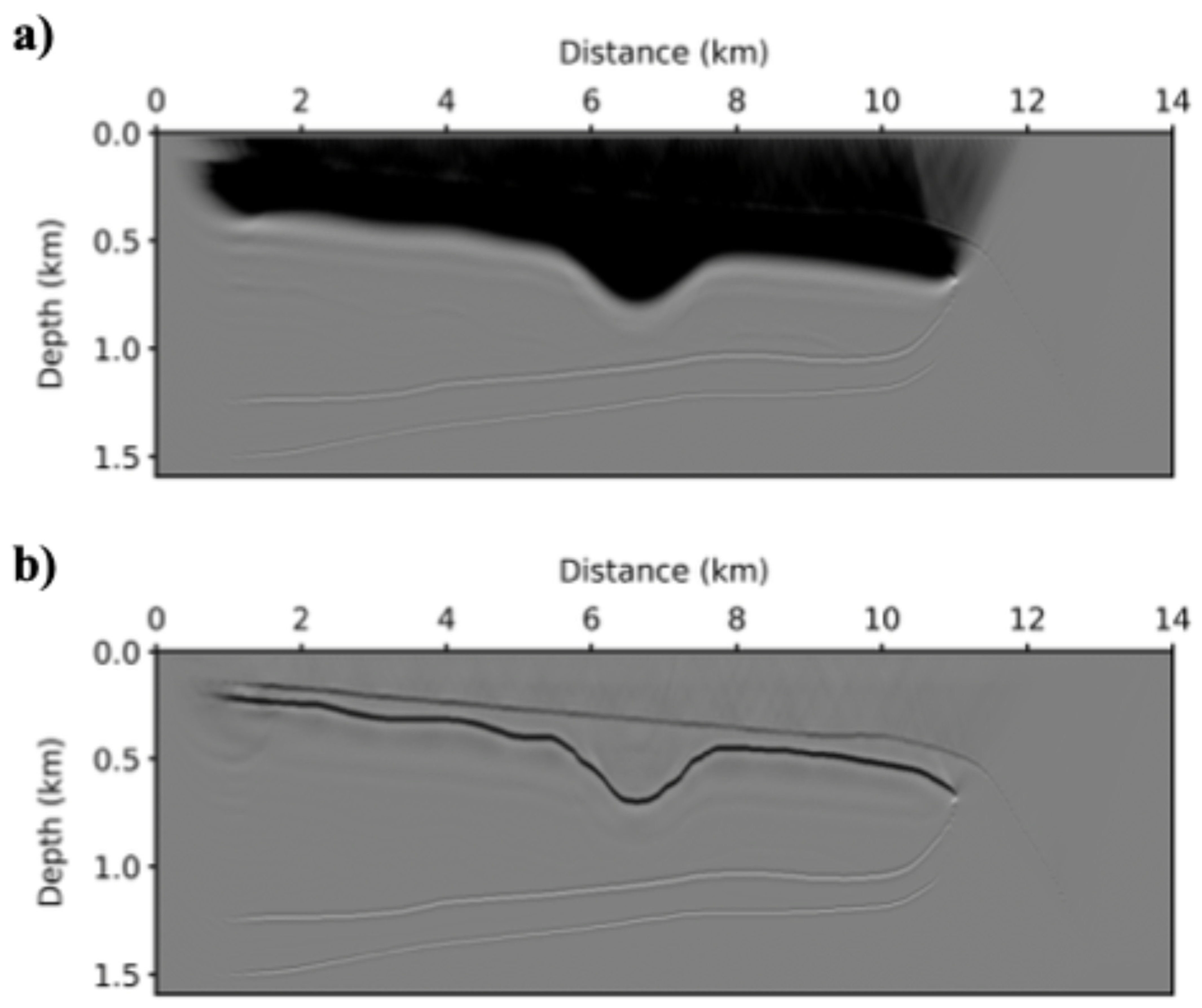
Conventional RTM can identify the top and bottom boundaries of the subsea permafrost, as shown in Figure 6a. However, the reflectors of the top part of the subsea permafrost structures are affected by strong low-wavenumber artifacts in a similar manner as in the previous numerical example. The bottom boundary reflection exhibits a relatively low amplitude compared to the top boundary. This issue arises from amplitude imbalance and low-wavenumber artifacts caused by the strong velocity contrast, which leads to backscattering. LSRTM can alleviate these problems. It removes strong low-wavenumber artifacts through LSRTM iteration and balances the reflector amplitudes, as shown in Figure 6b. Consequently, the LSRTM image identifies both the top and bottom boundaries of the subsea permafrost structures compared to the conventional RTM image. Moreover, the reflectors in the LSRTM image are sharper, indicating that LSRTM enhances the resolution of seismic images.

4. Seismic Imaging of Subsea Permafrost in the Arctic Continental Shelf

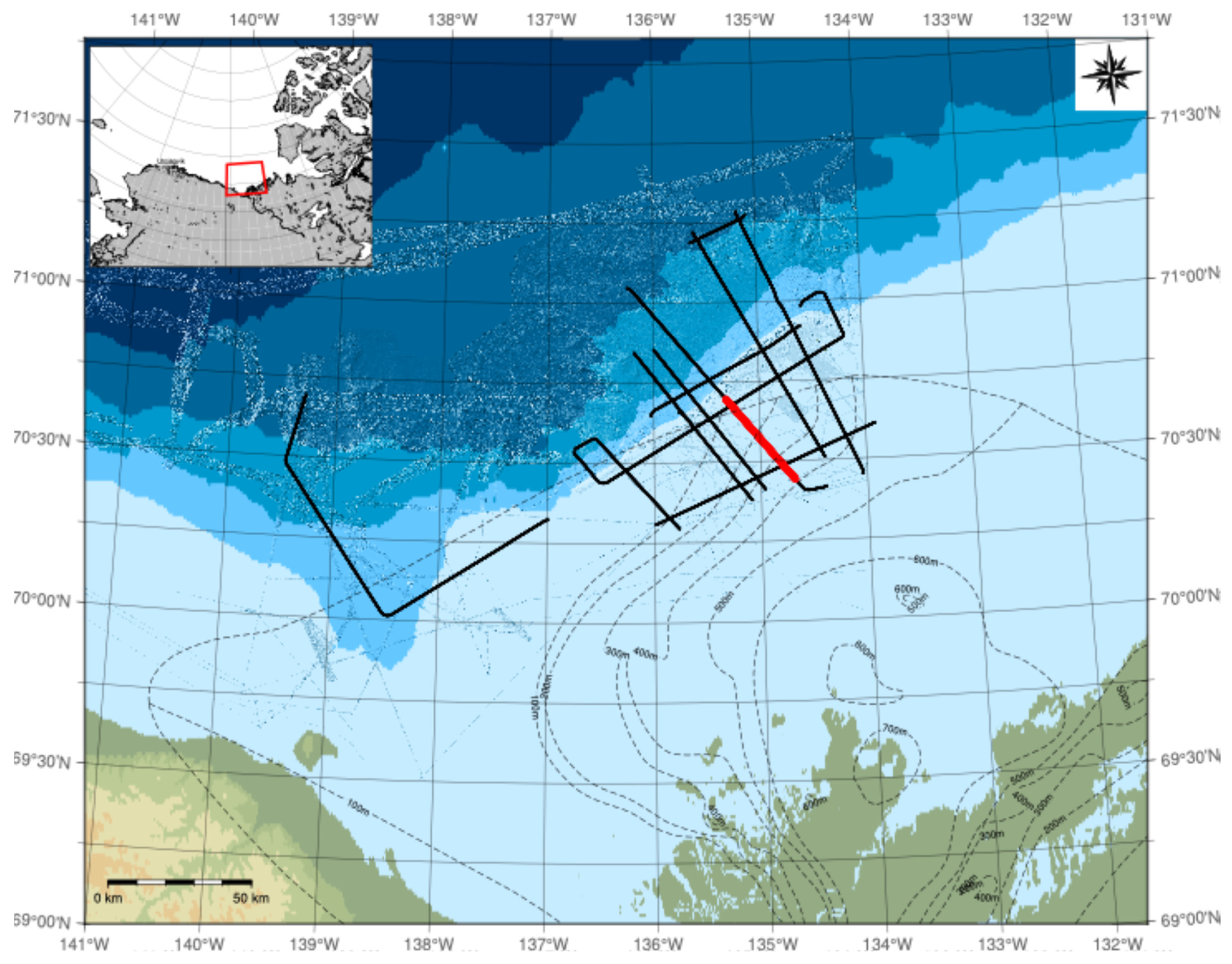
A seismic survey was conducted by the ice-breaking research vessel (IBRV) ARAON in 2014 to investigate the distribution and geophysical characteristics of the subsea permafrost in the continental shelf of the Canadian Beaufort Sea (CBS). In the CBS, many researchers have tried to identify the distribution of the subsea permafrost by using the seismic data analysis method such as seismic refraction data analysis, full waveform inversion, and so on [7,8,12]. Figure 7 shows the track chart, which represents the seismic survey lines. Among several seismic survey lines, “ARA05C-L05” is chosen for this field application (see the solid red line in the map in Figure 7). This seismic survey line intersects the region where the subsea permafrost structures are known to be distributed via geophysical methods [7,12]. The seismic acquisition system of the multi-channel seismic dataset is equipped with the 120-channel streamer with an active length of 1.5 km and an air-gun array with a total volume of 19.7 L. The shot and receiver intervals are 50 and 12.5 m, respectively. Detailed acquisition geometry and parameters are presented in Figure 8.
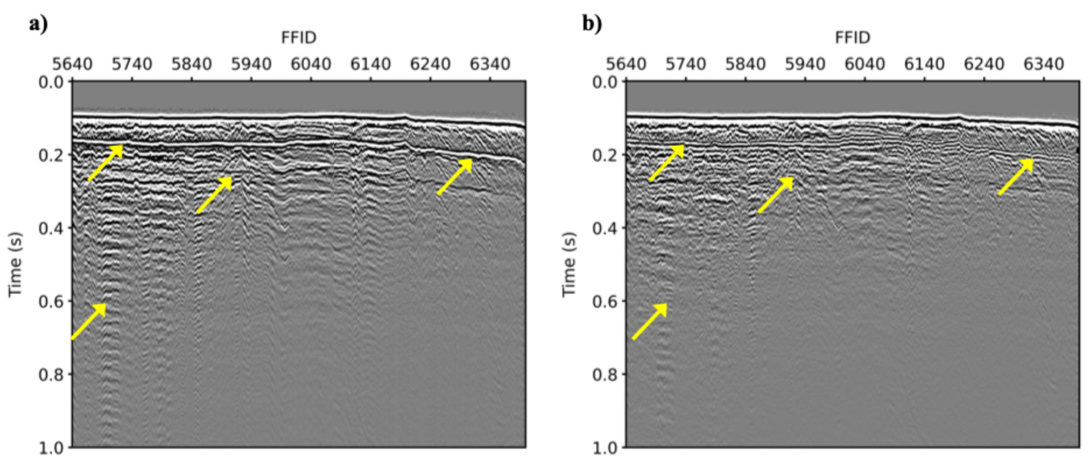
Several preprocessing steps of the field dataset were needed for the seismic imaging of the Arctic subsea permafrost from the acquired seismic dataset. Marine seismic data often contain noisy signals, such as low-frequency noise arising from swell or mechanical factors. To address this, frequency filtering, direct wave muting, and noise attenuation were applied to the field dataset to remove these noise signals. Figure 9a shows the common receiver gather for the first channel of the field dataset. However, because of a shallow water environment and high-velocity structures arising from subsea permafrost, this seismic dataset suffers from free surface multiples and internal multiple reflections. These multiple reflections are the main obstacle for imaging the subsea permafrost structure and estimating the seismic velocity information from the conventional velocity analysis. In addition, LSRTM can only take the primary signal, which is the first scattering reflection, into consideration. Hence, free surface and internal multiple reflections should be eliminated. Demultiple modules such as deterministic water-layer demultiple (DWD) and surface-related multiple elimination (SRME) embedded in Omega2 seismic data processing software version 2022 developed by Schlumberger were applied to our field dataset to attenuate the multiple reflections. The common receivers after demultiple procedures are displayed in Figure 9b. It is obvious that free-surface and internal multiple reflections are significantly attenuated after demultiple procedures. To transform data from 3D to 2D, we multiply the t in the time domain and i ω in the frequency domain to correct the amplitude and phase information, respectively. In this field application, rather than source estimation, we convolved the 40 Hz centroid frequency Ricker wavelet to field data.
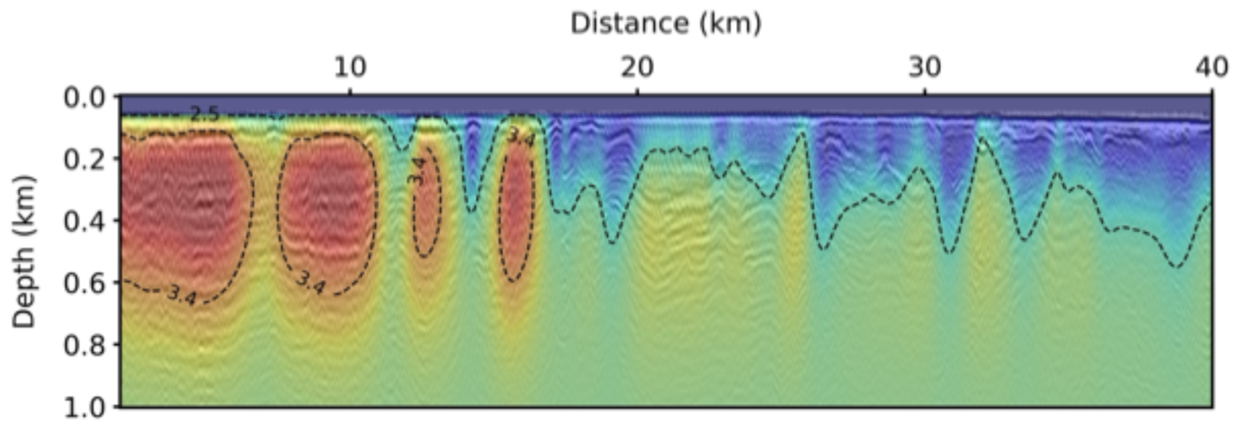
We utilize a P-wave velocity model obtained through Laplace-domain full waveform inversion for the background velocity model in this field data application [12]. This model is designed to account for multiple reflections, thereby enhancing velocity estimation accuracy. Figure 10 displays the background velocity model using the Laplace-domain full waveform inversion method for the field data application, which is discretized into a grid of 6.25 m spacing horizontally and vertically, with dimensions of 6401 × 161. In implementing LSRTM, we employ the preconditioned conjugate gradient method as the optimization scheme to minimize the misfit function defined by the L2-norm. We set the maximum number of iterations to 30 to ensure convergence and accuracy in the migration process.
Figure 11a,b show the seismic images of the subsea permafrost structures obtained from conventional RTM and LSRTM, respectively. The migrated image obtained from conventional RTM can image the geological structure; it suffers from robust and low-wavenumber artifacts in the shallow part. In contrast, LSRTM produces an enhanced migration image with balanced amplitude and high resolution. Furthermore, iterative procedures in LSRTM effectively attenuate low-wavenumber artifacts. Figure 12 shows the misfit history for the real data application. After the 30th iteration of LSRTM, the normalized misfit reaches values below 0.6. To evaluate the imaging result for subsea permafrost, we overlayed the LSRTM result on the background velocity model, displayed in Figure 13. According to Johansen et al. (2003) [38], subsea permafrost with ice contents ranging from 40 to 100% exhibit theoretical seismic velocities above 3.4 km/h. We contour the corresponding velocity boundary as a black dashed line in Figure 13, assuming it represents the boundaries of the subsea permafrost structures. According to these contour lines, the subsea permafrost structures are distributed on the left side in Figure 13. Based on this contour line indicating the subsea permafrost, there are reflection events representing the upper boundary of the subsea permafrost at approximately 6–70 m below the seafloor, which is the reasonable location according to statements from several studies [7,37]. These reflectors exhibit strong reflectivity due to the substantial velocity contrast associated with subsea permafrost. Therefore, LSRTM effectively delineates the upper boundary of the subsea permafrost in the migrated image. Furthermore, LSRTM balanced the amplitude of reflectors in the lower part of the subsea permafrost.
Unlike the upper boundary of the subsea permafrost, the bottom bound of the subsea permafrost is difficult to identify in the seismic images. Several factors contribute to the difficulty in imaging the bottom bound of the subsea permafrost. Firstly, residual multiple reflections pose a significant obstacle. The abnormal velocity characteristics of the subsea permafrost consist of a massive lump of ice that generates multiple free-surface and internal reflections. Subsea permafrost typically occurs in shallow water depths on continental shelves, exacerbating reverberations that produce short-period multiple reflections. Despite employing advanced demultiple algorithms to attenuate these reflections in this study, residual multiple reflections may persist in the seismic data. Only primary reflections are considered in LSRTM, which assumes the first-scattering approximation. Consequently, residual multiple reflections are treated as primary reflections during LSRTM and are migrated. Including spurious events from residual multiple reflections increases the likelihood of misinterpretation in the seismic migration section. While sophisticated demultiplexing techniques could enhance LSRTM performance, further investigation into these challenges lies beyond the scope of our research.
Secondly, another challenge lies in the accuracy of the background velocity model, particularly in the lower part. The background velocity we used in this study is obtained by the Laplace-domain full waveform inversion. Generally, the Laplace-domain full waveform inversion primarily exploits first arrival events for inverting the velocity information, which can represent only the upper part of the velocity model. Furthermore, the Laplace-domain full waveform inversion is usually implemented using the extremely low frequency components of the seismic data; the inverted velocity has low resolution. Based on these characteristics of the Laplace-domain full waveform inversion, the uncertainty of the lower part in our background velocity may exist and disturb the reflection event’s focus on their correct position during migration.
5. Conclusions

Subsea permafrost exhibits abnormally high-velocity characteristics due to its ice content, distinguishing it from the surrounding medium. While this velocity characteristic is valuable for detecting the extent of subsea permafrost, achieving high resolution in imaging has been challenging in previous studies. This article explores the feasibility of using LSRTM to achieve high-resolution seismic imaging of subsea permafrost in the Arctic. Synthetic experiments demonstrate that LSRTM produces high-quality migration images of subsea permafrost. Even with a short-offset streamer configuration during seismic data acquisition in the Arctic expedition, LSRTM successfully images both the top and bottom boundaries of the subsea permafrost. In this study, the assumed extent of subsea permafrost is delineated by a velocity contour line based on theoretical velocities described in the literature. Field applications in the Canadian Beaufort Sea confirm LSRTM’s capability to migrate the upper boundary of subsea permafrost under the continental shelf. These migrated events align closely with the velocity contour line defining the subsea permafrost. However, challenges still need to be addressed in identifying the bottom boundary of subsea permafrost, potentially due to issues such as imperfect multiple elimination or inaccuracies in the lower sections of the background velocity model. Nonetheless, reflectors beneath the subsea permafrost structure are imaged, demonstrating LSRTM’s effectiveness even with a short-offset streamer.

Author Contributions

S.K.: software, validation, data processing, writing—original draft preparation, and visualization; Y.C.: data preprocessing; J.-K.H.: project administration and funding; J.K.: noise attenuation for the field dataset data preprocessing; S.-G.K.: conceptualization, methodology, writing—review and editing, and formal analysis. All authors have read and agreed to the published version of the manuscript.

Funding

This work is supported by the research project entitled “Survey of Geology and Seabed Environmental Change in the Arctic Seas”, funded by the Korean Ministry of Ocean and Fisheries (KIMST Grant 20210632).

Data Availability Statement

The original contributions presented in the study are included in the article, further inquiries can be directed to the corresponding author.

Acknowledgments

We thank the Korea Polar Research Institute (KORPI) for permission to publish this work and to show data examples.

Conflicts of Interest

Author Joonyoung Kwak was employed by the company Schlumberger. The remaining authors declare that the research was conducted in the absence of any commercial or financial relationships that could be construed as a potential conflict of interest.

References

  1. Claerbout, J.F. Toward a unified theory of reflector mapping. Geophysics 1971, 36, 467–481. [Google Scholar] [CrossRef]
  2. Hill, P.R.; Mudie, P.J.; Moran, K.; Blasco, S.M. A sea-level curve for the Canadian Beaufort shelf. Can. J. Earth Sci. 1985, 22, 1383–1393. [Google Scholar] [CrossRef]
  3. Ruppel, C. Permafrost-associated gas hydrate: Is it really approximately 1% of the global system? J. Chem. Eng. Data 2015, 60, 429–436. [Google Scholar] [CrossRef]
  4. Ruppel, C.D.; Kessler, J.D. The interaction of climate change and methane hydrates. Rev. Geophys. 2017, 55, 126–168. [Google Scholar] [CrossRef]
  5. Archer, D.; Buffett, B.; Brovkin, V. Ocean methane hydrates as a slow tipping point in the global carbon cycle. Proc. Natl. Acad. Sci. USA 2009, 106, 20596–20601. [Google Scholar] [CrossRef] [PubMed]
  6. Shakhova, N.; Semiletov, I.; Leifer, I.; Salyuk, A.; Rekant, P.; Kosmach, D. Geochemical and geophysical evidence of methane release over the East Siberian Arctic shelf. J. Geophys. Res. 2010, 115, C08007. [Google Scholar] [CrossRef]
  7. Pullan, S.E.; MacAuley, H.A.; Hunter JA, M.; Good, R.L.; Gagne, R.M.; Burns, R.A. Permafrost distribution determined from seismic refraction. In Marine Science Atlas of the Beaufort Sea: Geology and Geophysics/Atlas des Sciences Marines de la mer de Beaufort: Géologie et Géophysique; Pelletier, B.R., Ed.; Miscellaneous Report 40; Geological Survey of Canada: Ottawa, ON, Canada, 1987; p. 37. [Google Scholar] [CrossRef]
  8. Hunter, J.A.; Good, R.L.; Hobson, G.D. Mapping the Occurrence of Sub-Seabottom Permafrost in the Beaufort Sea by Shallow Refraction Techniques; Geological Survey of Canada: Ottawa, ON, Canada, 1974; pp. 91–94. [Google Scholar]
  9. MacAulay, H.A.; Hunter, J.A. Detailed seismic refraction analysis of ice-bonded permafrost layering in the Canadian Beaufort Sea. In Proceedings of the 4th Canadian Permafrost Conference, Fairbanks, AK, USA, 17–22 July 1983; pp. 256–267. [Google Scholar]
  10. Brothers, L.L.; Hart, P.E.; Ruppel, C.D. Minimum distribution of subsea ice-bearing permafrost on the U.S. Beaufort Sea continental shelf. Geophys. Res. Lett. 2012, 39, L15501. [Google Scholar] [CrossRef]
  11. Brothers, L.L.; Herman, B.M.; Hart, P.E.; Ruppel, C.D. Subsea ice-bearing permafrost on the US Beaufort Margin: 1. Minimum seaward extent defined from multi-channel seismic reflection data: Subsea Permafrost on the US Beaufort I. Geochem. Geophys. Geosyst. 2016, 17, 4354–4365. [Google Scholar] [CrossRef]
  12. Kang, S.G.; Jin, Y.K.; Jang, U.; Duchesne, M.J.; Shin, C.; Kim, S.; Riedel, M.; Dallimore, S.R.; Paull, C.K.; Choi, Y.; et al. Imaging the P-wave velocity structure of Arctic subsea permafrost using Laplace-domain full-waveform inversion. J. Geophys. Res. Earth Surf. 2021, 126, e2020JF005941. [Google Scholar] [CrossRef]
  13. Bustamante, J.; Fabien-Ouellet, G.; Duchesne, M.J.; Ibrahim, A. Understanding seismic velocity variations of subsea permafrost: A sensitivity study. Geophysics 2023, 88, R655–R669. [Google Scholar] [CrossRef]
  14. Bustamante, J.; Fabien-Ouellet, G.; Duchesne, M.J.; Ibrahim, A. Deep-learning viscoelastic seismic inversion for mapping subsea permafrost. Geophysics 2024, 89, R339–R353. [Google Scholar] [CrossRef]
  15. Ramachandran, K.; Bellefleur, G.; Brent, T.; Riedel, M.; Dallimore, S. Imaging permafrost velocity structure using high resolution 3D seismic tomography. Geophysics 2011, 76, B187–B198. [Google Scholar] [CrossRef]
  16. Claerbout, J.F. Earth Soundings Analysis: Processing versus Inversion; Blackwell Scientific Publications: Oxford, UK, 1992. [Google Scholar]
  17. Kühl, H.; Sacchi, M.D. Least-squares wave-equation migration for AVP/AVA inversion. Geophysics 2003, 68, 262–273. [Google Scholar] [CrossRef]
  18. Lu, S.; Liu, F.; Chemingui, N.; Valenciano, A.; Long, A. Leastsquares full-wavefield migration. Lead. Edge 2018, 37, 46–51. [Google Scholar] [CrossRef]
  19. Hu, H.; Liu, Y.; Zheng, Y.; Liu, X.; Lu, H. Least-squares Gaussian beam migration. Geophysics 2016, 81, S87–S100. [Google Scholar] [CrossRef]
  20. Yuan, M.; Huang, J.; Liao, W.; Jiang, F. Least-squares Gaussian beam migration. J. Geophys. Eng. 2017, 14, 184–196. [Google Scholar] [CrossRef]
  21. Yang, J.; Zhu, H.; McMechan, G.; Yue, Y. Time-domain leastsquares migration using the Gaussian beam summation method. Geophys. J. Int. 2018, 214, 548–572. [Google Scholar] [CrossRef]
  22. Dai, W.; Schuster, G.T. Plane-wave least-squares reverse-time migration. Geophysics 2013, 78, S165–S177. [Google Scholar] [CrossRef]
  23. Zeng, C.; Dong, S.; Wang, B. Least-squares reverse time migration: Inversion-based imaging toward true reflectivity. Lead. Edge 2014, 33, 962–968. [Google Scholar] [CrossRef]
  24. Zhang, Y.; Duan, L.; Xie, Y. A stable and practical implementation of least-squares reverse time migration. Geophysics 2015, 80, V23–V31. [Google Scholar] [CrossRef]
  25. Liu, X.; Liu, Y.; Lu, H.; Hu, H.; Khan, M. Prestack correlative leastsquares reverse time migration. Geophysics 2017, 82, S159–S172. [Google Scholar] [CrossRef]
  26. Wu, D.; Wang, Y.; Cao, J.; Da Silva, N.V.; Yao, G. Least-squares reverse-time migration with sparsity constraints. J. Geophys. Eng. 2021, 18, 304–316. [Google Scholar] [CrossRef]
  27. Kim, S.; Kim, Y.S.; Chung, W. Least-squares reverse time migration using the most energetic source wavefields based on excitation amplitude imaging condition. Geophys. Prospect. 2023, 71, 1438–1454. [Google Scholar] [CrossRef]
  28. Kim, S.; Kang, S.G.; Choi, Y.; Chung, W. Efficient extended least-squares reverse time migration based on an excitation amplitude imaging condition. Geophysics 2024, 89, S31–S45. [Google Scholar] [CrossRef]
  29. Bleistein, N. On the imaging of reflectors in the earth. Geophysics 1987, 52, 931–942. [Google Scholar] [CrossRef]
  30. Yang, K.; Zhang, J. Comparison between Born and Kirchhoff operators for least-squares reverse time migration and the constraint of the propagation of the background wavefield. Geophysics 2019, 84, R725–R739. [Google Scholar] [CrossRef]
  31. Schuster, G.T. Seismic Inversion; Society of Exploration Geophysicists: Houston, TX, USA, 2017. [Google Scholar]
  32. Liu, Q.; Peter, D. One-step data-domain least-squares reverse time migration. Geophysics 2018, 83, R361–R368. [Google Scholar] [CrossRef]
  33. Chen, Y.; Dutta, G.; Dai, W.; Schuster, G.T. Q-least-squares reverse time migration with viscoacoustic deblurring filters. Geophysics 2017, 82, S425–S438. [Google Scholar] [CrossRef]
  34. Dai, W.; Wang, X.; Schuster, G.T. Least-squares migration of multisource data with a deblurring filter. Geophysics 2011, 76, R135–R146. [Google Scholar] [CrossRef]
  35. Dussaud, E.; Symes, W.W.; Williamson, P.; Lemaistre, L.; Singer, P.; Denel, B.; Cherrett, A. Computational strategies for reverse-time migration. In SEG Technical Program Expanded Abstracts; Society of Exploration Geophysicists: Houston, TX, USA, 2008; pp. 2267–2271. [Google Scholar]
  36. Komatitsch, D.; Martin, R. An unsplit convolutional perfectly matche d layer improved at grazing incidence for the seismic wave equation. Geophysics 2007, 72, SM155–SM167. [Google Scholar] [CrossRef]
  37. Taylor, A.E.; Dallimore, S.R.; Hill, P.R.; Issler, D.R.; Blasco, S.; Wright, F. Numerical model of the geothermal regime on the Beaufort shelf, arctic Canada since the Last Interglacial. J. Geophys. Res. 2013, 118, 2365–2379. [Google Scholar] [CrossRef]
  38. Johansen, T.A.; Digranes, P.; van Schaack, M.; Lønne, I. Seismic mapping and modeling of near-surface sediments in polar areas. Geophysics 2003, 68, 566–573. [Google Scholar] [CrossRef]
Figure 1. Workflow of the least-squares reverse time migration based on Kirchhoff approximation.
Remotesensing 16 03425 g001
Figure 2. Simple velocity model for subsea permafrost structure. (a) True velocity model, and (b) migration velocity model.
Remotesensing 16 03425 g002
Figure 3. (a) RTM image, and (b) LSRTM image at 10th iteration.
Remotesensing 16 03425 g003
Figure 4. Misfit history of LSRTM for the simple velocity model.
Remotesensing 16 03425 g004
Figure 5. Realistic velocity model for subsea permafrost structures. (a) True velocity model, and (b) migration velocity model.
Remotesensing 16 03425 g005
Figure 6. (a) RTM image, and (b) LSRTM image at 10th iteration.
Remotesensing 16 03425 g006
Figure 7. Track chart of seismic survey in the Canadian Beaufort Sea for implementing LSRTM. The red line represents the seismic survey line of the seismic dataset used in our field application.
Remotesensing 16 03425 g007
Figure 8. Schematic diagram for illustrating the seismic acquisition system in R/V ARAON.
Remotesensing 16 03425 g008
Figure 9. Common receiver gathers at 1first channel. (a) Before preprocessing, and (b) after preprocessing. Yellow arrows denote that demultiple process attenuated the multiple reflections.
Remotesensing 16 03425 g009
Figure 10. Migration velocity model for field application, obtained from Laplace-domain full waveform inversion [12].
Remotesensing 16 03425 g010
Figure 11. Migration results. (a) RTM image, (b) LSRTM image at 30th iteration. Yellow arrows denote the enhanced amplitude after LSRTM.
Remotesensing 16 03425 g011
Figure 12. Misfit history of LSRTM for the simple velocity model.
Remotesensing 16 03425 g012
Figure 13. The overlaid results between the migration velocity model and the LSRTM seismic image are shown in Figure 10 and Figure 11b.
Remotesensing 16 03425 g013
Disclaimer/Publisher’s Note: The statements, opinions and data contained in all publications are solely those of the individual author(s) and contributor(s) and not of MDPI and/or the editor(s). MDPI and/or the editor(s) disclaim responsibility for any injury to people or property resulting from any ideas, methods, instructions or products referred to in the content.