Article

A New Approximation Modeling Method for the Triaxial Induction Logging in Planar-Stratified Biaxial Anisotropic Formations

1
National Key Laboratory of Deep Oil and Gas, China University of Petroleum (East China), Qingdao 266580, China
2
School of Geosciences, China University of Petroleum (East China), Qingdao 266580, China
3
Sinopec Matrix Corporation, Qingdao 266075, China
*
Author to whom correspondence should be addressed.
Remote Sens. 2024, 16(16), 3076; https://doi.org/10.3390/rs16163076
Submission received: 15 May 2024 / Revised: 12 August 2024 / Accepted: 19 August 2024 / Published: 21 August 2024
(This article belongs to the Special Issue Recent Advances in Underwater and Terrestrial Remote Sensing)

Abstract

:
A novel and efficient modeling approach has been developed for simulating the responses of triaxial induction logging (TIL) in layered biaxial anisotropic (BA) formations. The core of this innovative technique lies in analytically calculating the primary fields within a homogeneous medium and approximating the scattered fields within layered formations. The former involves employing a two-level subtraction technique. Initially, the first-level subtraction entails altering the direction of the Fourier transform to mitigate the integral singularity of the spectral fields, particularly in high-angle and horizontal wells. Conversely, the second-level subtraction aims to further optimize integral convergence by creating an equivalent unbounded transverse isotropic (TI) formation and eliminating the corresponding spectral fields. With the two-level subtractions, the convergence of the spectral field has been enhanced by more than six orders of magnitude. Additionally, a strict recursive algorithm and approximation method are developed to compute the scattered fields in layered biaxial anisotropic media. The rigorous algorithm is based on a modified amplitude propagator matrix (MAPM) approach and serves as the benchmark for the approximation method. In contrast, the approximation method exploits the similarity between the spectral scattered field of the TI medium and the BA medium, establishing corresponding equivalent layered TI models for each magnetic component. Since the scattered field in TI models only involves a one-dimensional semi-infinite integral, the computational complexity is significantly reduced. Numerical simulation examples demonstrate that the new simulation method is at least two orders of magnitude faster than the current modeling approach while maintaining computational precision error within 0.5%. This significantly improved simulation efficiency provides a solid foundation for expediting the logging data processing.

Graphical Abstract

1. Introduction

Formation anisotropy is prevalent in deep-water reservoirs and can be classified into micro-anisotropy and macro-anisotropy. The former is typically induced by directional grain deposition or micro-fracture development, whereas the latter occurs when the formation is thinner than the vertical resolution of the logging tool [1,2,3]. Accurately measuring formation resistivity around the borehole has always been a significant challenge in geophysical logging due to the influence of formation anisotropy [4,5]. Due to the special characteristics of the deep-water reservoir structure, high angle (HA) and horizontal (HZ) wells have become the main drilling method [6]. Existing electrical logging tools are primarily designed for isotropic formations, resulting in biased responses and inaccurate readings in HA and HZ wells with anisotropy. The triaxial induction logging (TIL) technique was developed to address the need to detect resistivities in different directions within the formation [7,8]. TIL measures the tensor magnetic field and provides rich formation information [9]. However, the responses of TIL in deviated wells are often non-linear, necessitating the use of fast inversion techniques for qualitative interpretation and quantitative evaluation of these data [10,11]. Existing inversion methods for TIL typically utilize parametric regularization gradient optimization algorithms, which require extensive forward modelling to compute the Jacobian matrix. Therefore, a fast and accurate forward simulator is essential for the rapid reconstruction of anisotropic resistivity from complex TIL data, considering its rich information content [12,13,14].
The fractured shale or tight sand formations can be depicted by a biaxial anisotropic (BA) model, where the conductivity varies in x, y and z directions. Considering the complexity of the forward model, the simulation of TIL in BA formations can be categorized into three types: numerical methods, hybrid methods and analytical methods [15,16]. The numerical and hybrid methods offer better accommodation with the complex borehole and formation structure. However, due to their low computational efficiency, these algorithms are seldom utilized in the practical logging data processing. Neglecting the effects of borehole, invasion and coil size, the analytical methods are commonly used to obtain TIL responses in one-dimensional (1D) media. The foundation of analytical methods lies in describing the propagation of electromagnetic (EM) waves in planar-stratified BA media. To this end, the generalized reflection matrix method and the coefficient propagation matrix method are developed [17,18,19]. The former involves complex formula derivation, while the latter often suffers from the issue of numerical overflow. Consequently, there still lacks a concise and stable algorithm for calculating the magnetic fields in layered BA media.
For the forward modeling of TIL in 1D formation, efficiently and accurately converting EM fields from the spectral domain to the spatial domain is a challenge. This conversion, also known as the inverse Fourier transform (IFT) or Sommerfeld integral, is significantly impacted by the integrand convergence [20,21,22]. IFT methods can be classified into the direct integral method and digital filter integral method. The former, e.g., Gauss–Laguerre integral and cubic spline interpolation, can offer controllable computation precision, albeit requiring excessive nodes for HA wells with slowly converging integrals. In contrast, the latter, such as the fast Hankel transform algorithm, can effectively alleviate slow integrand convergence, and has been widely used in the geophysical fields [23,24]. Unfortunately, both methods are inadequate for handling the case of HZ well case where the integral is non-convergent [25,26]. Hu et al. (2018) addressed this singularity by separating the primary fields from the total fields [27]. Similarly, Li et al. (2020) subtracted part of the primary spectral fields by constructing an equivalent transversely isotropy (TI) model [28]. The periodicity of kernel function is another factor dominating the modeling speed of TIL in BA medium. In homogeneous BA formation, Deng et al. (2020) utilized the field symmetry at four integral quadrants, giving rise to the computation speed improved by three times [29]. Later, Wang et al. (2023b) extended above property to a layered BA media [30]. However, the existing forward modeling techniques of TIL in layered BA medium are still limited in the efficient processing of the double IFT, and unable to meet the needs of real time data processing.
First, this paper introduces the principle of TIL, which explains the relationship between apparent conductivities and measured magnetic fields. Then, a two-level singularity subtraction scheme is established to significantly improve the convergence of the spectral primary field in homogeneous media. In Section 3, both the strict derivation and the approximation method for calculating the spectral scattered field in layered BA media are presented, and the accuracy and efficiency of the approximation method are verified. Finally, the accuracy and stability of the new forward modeling method are validated, and the characteristics of TIL responses under different anisotropy are discussed.

2. Physics of Triaxial Induction Logging

The TIL tool usually consists of a transmitter (T), bucking (B) coils and a receiver (R), all of which are composed of three mutually orthogonal coils oriented at the x, y and z directions, respectively. The specific structure and antenna configuration of the TIL tool are shown in Figure 1a. These tools typically operate within a frequency of 10 kHz to 200 kHz, with negligible impact from the coil size. TIL tools are capable of measuring the formation tensor voltage V ^ ,
V ^ = [ V x x V x y V x z V y x V y y V y z V z x V z y V z z ] ,
where Vij signifies the voltage component of j-oriented receiver emitted from an i-oriented transmitter. The voltage tensor V ^ is further converted into formation apparent conductivity σa by utilizing the tool coefficient K,
σ a = [ σ a x x σ a x y σ a x z σ a y x σ a y y σ a y z σ a z x σ a z y σ a z z ] = V ^ K ,
K = ( ω μ 0 ) 2 16 π L [ 2 A T x A R x N T x N R x 2 A T x A R y N T x N R y 4 A T x A R z N T x N R z 2 A T y A R x N T y N R x 2 A T y A R y N T y N R y 4 A T y A R z N T y N R z 4 A T z A R x N T z N R x 4 A T z A R y N T z N R y A T z A R z N T z N R z ] ,
where μ0 is the free-space magnetic permittivity, and ω is the angular frequency; L represents the spacing between the T and R; AT/AR and NT/NR represent the area and turns of the T/R, respectively.
The essence of TIL lies in measuring the magnetic field tensor H ¯ , V ^ = i ω μ A T A R N T N R H ¯ . The measurement of H ¯ in the tool coordinate system (X, Y, Z) not only depends on the spacing and operating frequency, but also relies on the geometric relationship between the TIL tool and the formation. As depicted in Figure 1b, the direction of the TIL tool is arbitrary put with respect to the principal axis of magnetic tensor H in the formation coordinate system (x, y, z). The magnetic field tensor at two coordinate systems is connected by a rotation matrix R,
H ¯ = R 1 H R , R = [ c o s α c o s β c o s α c o s β s i n α c o s β c o s α s i n β c o s β s i n α s i n β 0 0 c o s α ] ,
where α denotes the dipping angle between the tool and the normal of formation. β represents the azimuthal angle of the tool relative to formation.

3. Computation of Primary TIL Response in Homogeneous Formation

3.1. Spectral Primary Field in Homogeneous BA Medium

Assuming a harmonic source with e-iωt dependence, the Maxwell’s equations satisfy,
× E ( r ) = i ω μ 0 [ H ( r ) + M δ ( r ) ] , × H ( r ) = σ * E ( r ) ,
where M is the magnetic moment, M = Mxex + Myey + Mzez. E and H are electric and magnetic fields in the spatial domain, respectively. r (x, y, z) is the source position, and δ(·) is the Dirac function. μ0 is the free-space magnetic permittivity. σ* is the complex conductivity tensor, which can be expressed as follows
σ * = d i a g ( σ x * , σ y * , σ z * ) ,   σ i * = σ i i ω ε i ,
where σ is the formation conductivity, and Ɛ represents the dielectric constant.
Since the heterogeneity of formations only exists along the z-direction, the spatial EM fields can be converted to the spectral domain via a twofold Fourier transform. Hence, the tangential EM component satisfy the following expression,
z S ˜ ( k , z ) + U S ˜ ( k , z ) = [ d 1 d 2 ] δ ( z z a ) , S ˜ = [ E ˜ x E ˜ y H ˜ y H ˜ x ] T ,
where the matrix S ˜ is composed of spectral EM components to be solved, and kx and ky correspond to the wave numbers along the x- and y-axes, respectively. za signifies the vertical position of the dipole source. U is a 4 × 4 system matrix U = [ 0 u 1 u 2 0 ] , and d1 and d2 are the 2 × 1 source vector. The system matrix has four eigenvalues (λI, λII, −λI, −λII), and the corresponding eigenvectors form the eigenmatrix C, C = [ c 11 c 11 c 21 c 21 ] , where
u 1 = [ i ω μ k x 2 σ z * k x k y σ z * k x k y σ z * i ω μ k y 2 σ z * ] , d 1 = [ i ω μ M y i ω μ M x ] , u 2 = [ σ x * i k y 2 ω μ i k x k y ω μ i k x k y ω μ σ y * i k x 2 ω μ ] , d 2 = [ i k y M z i k x M z ] .
Mathematically, the solution of Equation (7) can be written as S ˜ = β S ˜ 1 + S ˜ 2 , β = { 0 ,   s o u r c e - f r e e 1 ,      s o u r c e . S ˜ 1 represents the spectral primary field, and S ˜ 2 denotes the spectral scattered fields. In a homogeneous BA medium, applying the Fourier transform along the z-direction, the spectral primary field can be further written as,
S ˜ 1 ( k x , k y , k z ) = S ˜ p ( k x , k y , k z ) [ d 1 d 2 ] , S ˜ p ( k x , k y , k z ) = ( U + i k z I ) * | U + i k z I | ,
where kz corresponds to the wave numbers along the z-axe, and the superscript * demotes the adjoint matrix. Performing the IFT on Equation (9) and then combining with the residue theorem, the analytical expression of the spectral primary fields in homogeneous BA medium can be obtained (Yuan et al., 2010),
S ˜ p ( k x , k y , z ) = { ( U λ I I ) * e λ I ( z z a ) 2 λ I ( λ I I 2 λ I 2 ) ( U λ I I I ) * e λ I I ( z z a ) 2 λ I I ( λ I I 2 λ I 2 ) , z > z a ( U + λ I I ) * e λ I ( z z a ) 2 λ I ( λ I I 2 λ I 2 ) ( U + λ I I I ) * e λ I I ( z z a ) 2 λ I I ( λ I I 2 λ I 2 ) , z < z a .
Generally, the contribution of primary fields exceeds 95% in the total field (Løseth and Ursin B, 2007). Hence, achieving a swift and precise primary field calculation is imperative. In order to derive the spatial primary field, it is mandatory to implement the following double IFT,
S 1 ( r ) = 1 4 π 2 S ˜ 1 ( k x , k y , z ) e i k x x + i k y y d k x d k y .
To mitigate the computational complexity, the spectral EM fields at four quadrants are observed to exhibit symmetric or antisymmetric expressions in the homogeneous medium. Recently, Wang et al. (2023b) extends this symmetry analysis to the layered BA media. Hence, the original infinite integral in Equation (11) is simplified to a semi-infinite one, resulting in a three-quarters reduction in the computational burden for the IFT. Table 1 further illustrates the relationships of spectral magnetic fields at different quadrants. The spectral field obtained in the first quadrant is used as the reference (denoted by a plus sign) and compared to the spectral fields in the other quadrants with it, indicating the opposite direction with a minus sign. For instance, when calculating Hxx, the simplified integral takes the following form,
H x x ( r ) = 1 4 π 2 0 0 H ˜ x x ( k x , k y , z ) ( e 1 e 2 + e 3 e 4 ) d k x d k y ,
where H ˜ x x ( k x , k y , z ) represents the spectral field of xx component in the first quadrant (kx > 0, ky > 0), e 1 = e i k x x + i k y y , e 2 = e i k x x + i k y y , e 3 = e i k x x i k y y , e 4 = e i k x x i k y y .

3.2. The Two-Level Subtraction of Spectral Primary Fields

Although the computation of the double IFT can be greatly reduced by exploiting the symmetry of the spectral primary field, the high oscillation and low convergence of the integral kernel usually result in poor accuracy and high computational complexity of the double semi-infinite integral. In order to improve the convergence of the integral kernel function, a two-level subtraction scheme based on a homogenous BA model is introduced in this section. The first-level subtraction is based on the principle of coordinate transform, which determines the direction of the optimal Fourier transform by the position of the receiver. Specifically, the projection lengths of the tool are acquired along the x-, y- and z-axes, and then Fourier transform is performed along the two directions with the smaller length. The second-level subtraction involves constructing an equivalent TI medium, subtracting the contribution of the spectral primary fields of TI medium and evaluating the residual spectral primary fields. The TI medium can be regarded as a special case of the BA medium, i.e., σx = σy, and the spectral primary fields of the two model have similar convergence properties. Since the spectral primary fields of the TI medium are analytical, the spectral primary fields of homogeneous BA medium can be written as follows,
S 1 ( r ) = 1 4 π 2 S ˜ r e s 1 e i ( l k l + q k q ) d k l d k q + S T I 1 ( r ) ,   S ˜ r e s 1 = S ˜ 1 S ˜ T I 1 ,
where S ˜ r e s 1 is the residual field in a BA medium after subtracting the primary field of a TI medium. l and q represent the directions of the Fourier transform, while kl and kq denote the wave numbers corresponding to l and q.
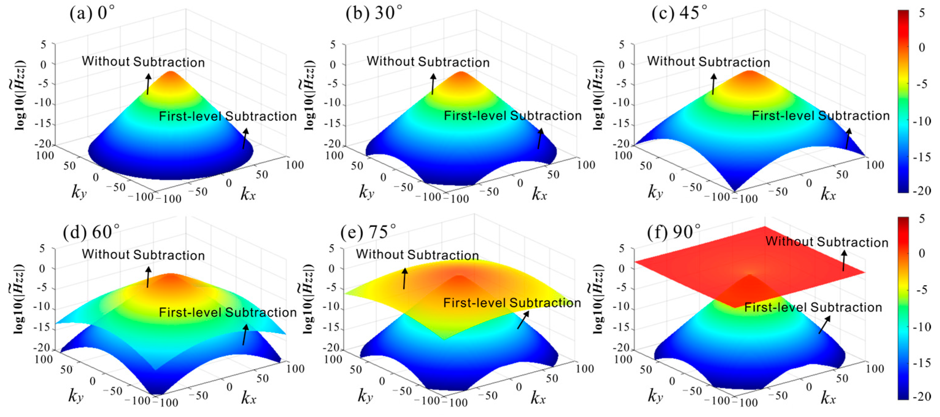
In order to evaluate the effectiveness of the two-level subtraction scheme, a homogeneous BA model is established with conductivity σ = diag{1, 0.5, 0.25} S/m. Figure 2 shows the TIL responses of the coaxial magnetic component for α = 0°, 30°, 45°, 60°, 75° and 90° with the operation frequency of 10 kHz and a spacing of 0.5 m. The upper floating layer in Figure 2 represents the spectral primary fields without subtraction, while the lower floating layer depicts the spectral primary fields after the first-level subtraction. Evidently, the convergence of the spectral primary fields decreases with increasing α and fails in HZ wells. However, the first-level subtraction scheme notably enhances the convergence of spectral primary fields in HA wells and resolves the non-convergence issue in HZ wells, albeit proving impractical for low-dipping wells (α ≤ 45°).
In contrast, Figure 3 compares the results obtained using the first-level subtraction with those using the second-level subtraction, where the equivalent TI medium of the second-level subtraction has the horizontal conductivity σh = sqrt (σx* σy) and the vertical conductivity σv = σz. It can be found that the second-level subtraction further enhances the convergence of the spectral primary fields by over four orders of magnitude, making it suitable for any dipping wells. Therefore, the two-level subtraction scheme effectively mitigates the integral singularity and computation complexity, increasing the calculation speed of the primary fields in the homogeneous BA medium by over ten times.

3.3. Optimal Construction of Equivalent TI Medium

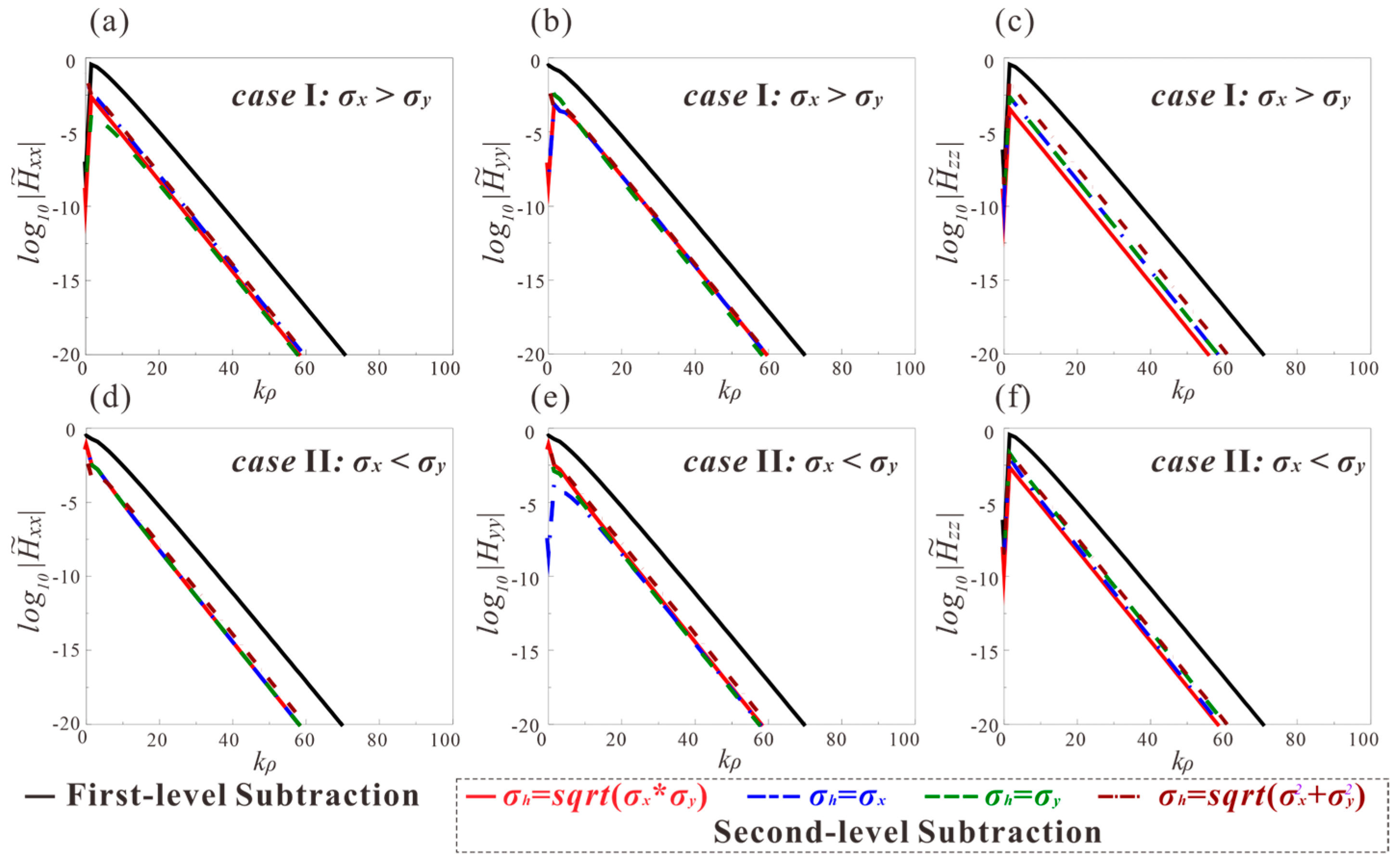
To ensure the best convergence enhancement, this subsection explores the optimal construction of equivalent TI models for both coaxial and coplanar magnetic components. Figure 4 shows the convergence of the spectral magnetic components using different equivalent TI models in the vertical well, where kρ = sqrt ( k x 2 + k y 2 ). The black solid line signifies the convergence of the spectral primary field after the first-level subtraction, while the other lines represent the convergence of the residual fields after the second-level subtraction using different equivalent models. Here, four equivalent TI media are considered, all models sharing identical vertical conductivity, σv = σz. In contrast, the horizontal conductivities of four models are set as σh = sqrt (σx* σy), σh = σy, σh = σx and σh = sqrt ( σ x 2 + σ y 2 ). Additionally, two scenarios of BA cases (σx > σy and σx= < σy) are considered. Figure 4a–c uses a homogeneous BA medium with conductivity of [σx, σy, σz] = [1, 0.5, 0.25] S/m, while Figure 4d–f is computed with [σx, σy, σz] = [0.5, 1, 0.25] S/m. Taking the H ˜ x x component as an example, it is observed that employing four distinct equivalent TI model constructions yields comparable results for the scenario where σx > σy, with the approach of σh = σy slightly outperforming the other three methods. This trend presents in the scenario where σx < σy. Likewise, the optimal TI model construction for the H ˜ y y and H ˜ z z components are σh = σx and σh = sqrt (σx* σy), respectively.
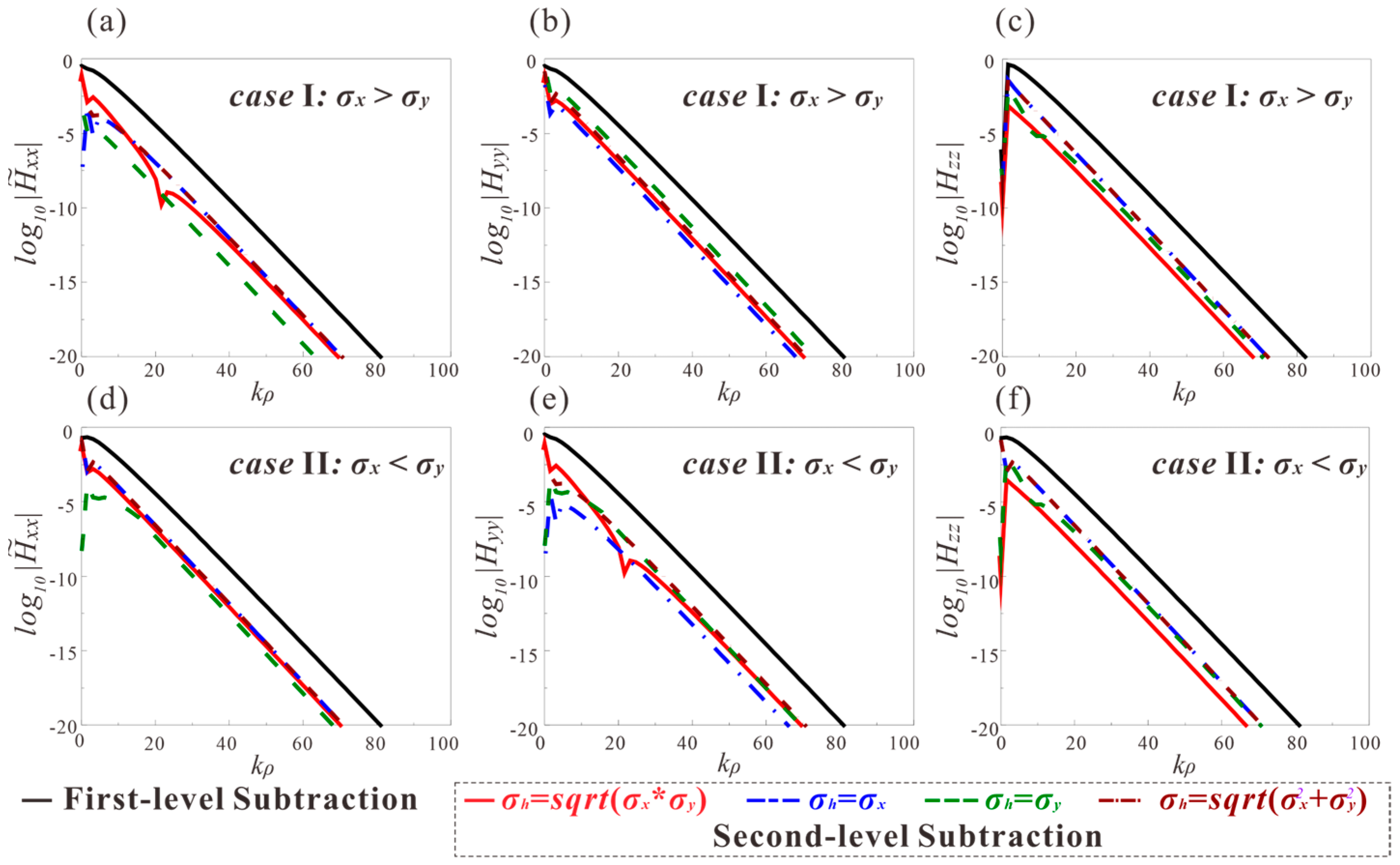
To further clarify the effectiveness of the aforementioned equivalent model, Figure 5 illustrates the convergence of magnetic components after the second-level subtraction in HZ wells. In contrast to the vertical wells, notable disparities emerge in the effect of second-level subtraction when constructing different equivalent TI models for the HZ wells. The subtracted spectral fields with the optimal TI models in the vertical well converge much faster. Therefore, the optimal equivalent TI model for coaxial and coplanar components in HZ wells remains consistent with that in vertical wells, regardless of variations in the dip angle.

4. Rapid Computation of Scattered Fields in Layered BA Formations

4.1. The Modified Amplitude Propagator Matrix (MAPM) Algorithm

In contrast to the primary fields, analytical expression for the scattered fields in layered BA formations are unavailable, posing significant challenges for the fast computations of TIL responses. To drive the scattered fields, a mandatory approach is a recursive algorithm, such as the amplitude propagator matrix algorithm. In layered BA formation, the scattered fields at the j-th layer can be formulated as follows,
S ˜ j 2 = C j [ e Λ j ( z z j 1 ) 0 0 e Λ j ( z z j ) ] [ v j w j ] ,
where
v j = [ v I , j , v I I , j ] T ,   w j = [ w I , j , w I I , j ] T ,   Λ j = d i a g { λ I , j , λ I I , j } ,   C j = [ c 11 , j c 11 , j c 21 , j c 21 , j ] .
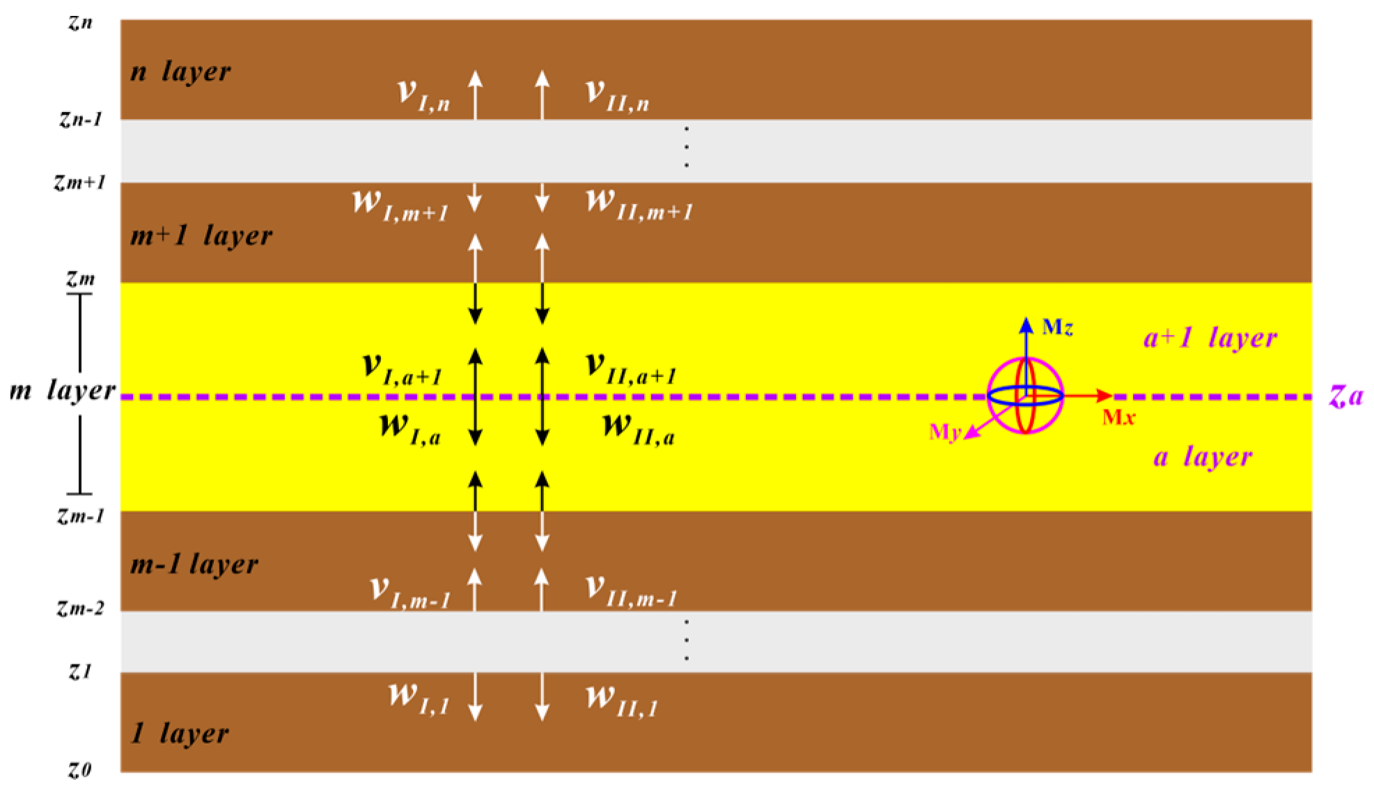
assuming that the number of layers in formation is n, and the propagation of EM waves in a layered medium is shown in Figure 6. In theory, vj and wj are the amplitude of upgoing and downgoing waves at the lower and upper boundaries of the j-th layer, respectively. Since there is no upgoing wave in the first layer, vI,1 = vII,1 = 0. Similarly, there is no downgoing wave in the last layer, wn = 0.
Considering the continuity condition satisfied by the amplitude of upgoing/downgoing waves at each boundary, the propagation of EM waves in a layered medium can be obtained. Take the boundary at z = zj as an example, the continuous tangential EM fields of adjacent layers are formulated as follows
F j [ v j w j ] G j + 1 [ v j + 1 w j + 1 ] = [ ζ j + 1 S ˜ z j z a p ( z j ) ζ j S ˜ z j < z a p ( z j ) ] [ d 1 d 2 ] ,
where if the source embedded in the i-th layer, ζ i = 1 otherwise ζ i = 0 . Fj and Gj+1 are written as follows,
F j = C j [ e Λ j ( z j z j 1 ) 1 ] , G j + 1 = C j + 1 [ 1 e Λ j + 1 ( z j z j + 1 ) ] .
In the traditional coefficient propagator matrix algorithm, the amplitudes of upgoing and downgoing waves in each layer are typically treated as a propagator pair, [vj, wj]T. When solving for the amplitude matrix, we need to obtain the inverse of matrices F and G. Unfortunately, problems arise when λ takes on a large value, such as in the case of thick layers or high wave numbers. In such situations, F−1 and G−1 tend to be ill-conditioned, leading to a numerical overflow issue.
To accurately stably and stably determine the unknown wave amplitudes, a modified amplitude propagator matrix (MAPM) algorithm is proposed. This algorithm establishes the relationship between three constructive amplitude terms of upgoing and downgoing waves at three adjacent boundaries. Hence, Equation (16) is written as follows,
R 2 j 1 x 2 j 2 + Q 2 j 1 x 2 j 1 + T 2 j 1 x 2 j = o 2 j 1 R 2 j x 2 j 1 + Q 2 j x 2 j + T 2 j x 2 j + 1 = o 2 j
where x2j−1 = wj, x2j = vj+1, and
{ R 2 j 1 = ( c 11 , j c 21 , j + 1 + c 11 , j + 1 c 21 , j ) e Λ j ( z j z j 1 ) Q 2 j 1 = c 11 , j c 21 , j + 1 c 11 , j + 1 c 21 , j T 2 j 1 = c 11 , j + 1 c 21 , j + 1 c 11 , j + 1 c 21 , j + 1 o 2 j 1 = c 21 , j + 1 [ ζ j + 1 S ˜ z j z a p ( z j ) ζ j S ˜ z j < z a p ( z j ) ] d 1 + c 11 , j + 1 [ ζ j + 1 S ˜ z j z a p ( z j ) ζ j S ˜ z j < z a p ( z j ) ] d 2 ,   { R 2 j = c 11 , j c 21 , j + c 11 , j c 21 , j Q 2 j = c 11 , j c 21 , j + 1 c 11 , j + 1 c 21 , j T 2 j = ( c 11 , j + 1 c 21 , j c 11 , j c 21 , j + 1 ) e Λ j + 1 ( z j z j + 1 ) o 2 j 1 = c 21 , j [ ζ j + 1 S ˜ z j z a p ( z j ) ζ j S ˜ z j < z a p ( z j ) ] d 1 c 11 , j [ ζ j + 1 S ˜ z j z a p ( z j ) ζ j S ˜ z j < z a p ( z j ) ] d 2 .
assuming the MD source is located at the m-th layer, and its vertical position is za, as illustrated in Figure 6. Applying Equation (18) to all boundaries, the amplitude of upgoing/downgoing waves at any boundary can be obtained recursively. For example, if we start from z1 and recursively backward to zn-1, the x2n-1 can be obtained directly,
x 2 n 1 = ( 1 ) 2 n i = 2 m 2 n 1 R i ( Q i R i T i 1 ) 1 [ ( Q 2 a + R 2 a T 2 a 1 ) ψ 1 R 2 m 1 ψ 2 ] T 2 a 1 ( 1 T 2 n 1 Q 2 n 1 R 2 n ) 1
where
ψ 1 = c 21 , m 1 [ ζ a S ˜ z m 1 z a p ( z m 1 ) ζ m 1 S ˜ z m 1 < z a p ( z m 1 ) ] s 1 c 11 , m 1 [ ζ a S ˜ z m 1 z a p ( z m 1 ) ζ m 1 S ˜ z m 1 < z a p ( z m 1 ) ] s 2
ψ 2 = c 21 , m ζ m S ˜ p ( z a ) s 1 + c 11 , m ζ m S ˜ p ( z a ) s 2
T j = { Q j 1 T j , j = 1 ( Q j R j T j 1 ) 1 T j , j = 2 , , 2 n 3
where the superscript −1 represents the inverse operator of the matrix. It should be highlight that the computational stability of Equations (20)–(23) primarily depends on Q j 1 . Since Q j 1 is composed of the eigenvectors of the system matrix U, this term always exists, ensuring that there is no numerical overflow problem during the calculation of the MAPM algorithm.
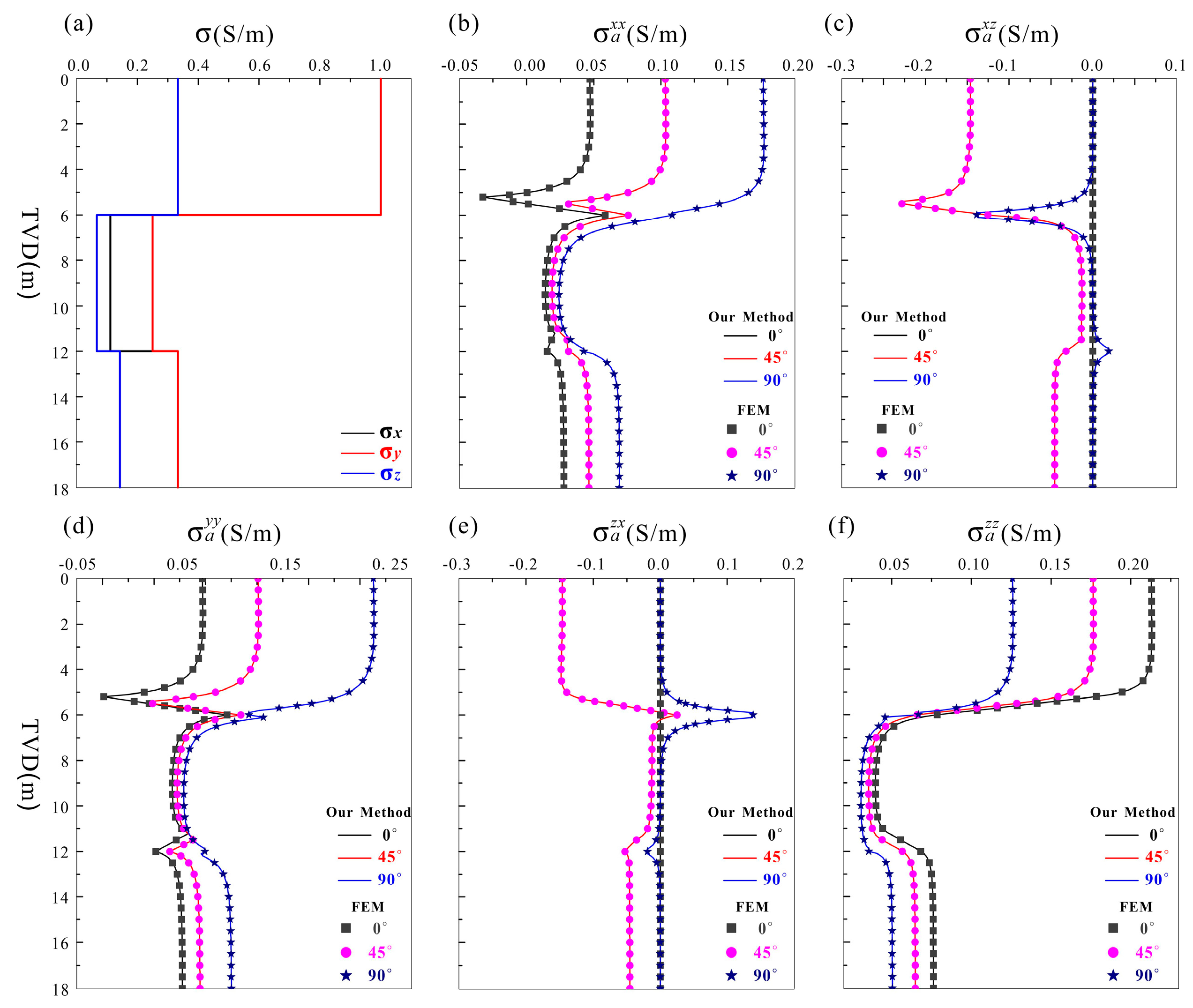
In order to verify the accuracy of the MAPM algorithm, a three-layer model is depicted in Figure 7, where the upper and lower surrounding rocks contain a TI medium, the middle layer features a BA medium, and the specific conductivity of each layer is shown in the figure. Figure 8b–f represents the components’ responses of TIL for different dip angles in the three-layer model. The solid lines are the computation results of the MAPM algorithm, and the scattered points represent the simulation results of the finite element method (FEM) with the operation frequency of 10 kHz and a spacing of 0.5 m. Obviously, the calculation results of the two methods coincide in any dipping wells, which verifies the accuracy of the MAPM method.
Although the recursive nature of the MAPM method is straightforward, it necessitates a significant number of operations on 2 × 2 matrices and does not circumvent the need to solve the double IFT, which leads to the large calculation time of the MAPM method in the case of a large number of layers.

4.2. Approximating the Scattered Fields with Layered TI Model

An approximation method with the layered TI model is built to further accelerate the solving of the scattered fields in the layered BA formation. Hence, the calculation for the scattered field of the layered TI model is well developed, enabling the simplification of the dual infinite integral into a one-dimensional infinite integral, commonly referred to as the Sommerfeld integral, which effectively reduces the computational complexity. In addition, as mentioned in Section 3.3, the spectral scattered fields in layered media also satisfy the symmetry and anti-symmetry. Therefore, the infinite integral can be further simplified to a semi-infinite integral,
S T I 2 ( r ) = 1 4 π 2 S ˜ T I 2 e i ( l k l + q k q ) d k l d k q = 1 4 π 2 0 S ˜ T I 2 J n ( k ρ ρ ) d k ρ ,
where Jn(·) is the n-th Bessel function, and n = 0, 1. S T I 2 and S ˜ T I 2 represent the spatial and spectral scattered field in the TI model, respectively. After the above simplification, the computational speed of the scattered field can be increased by one order of magnitude.
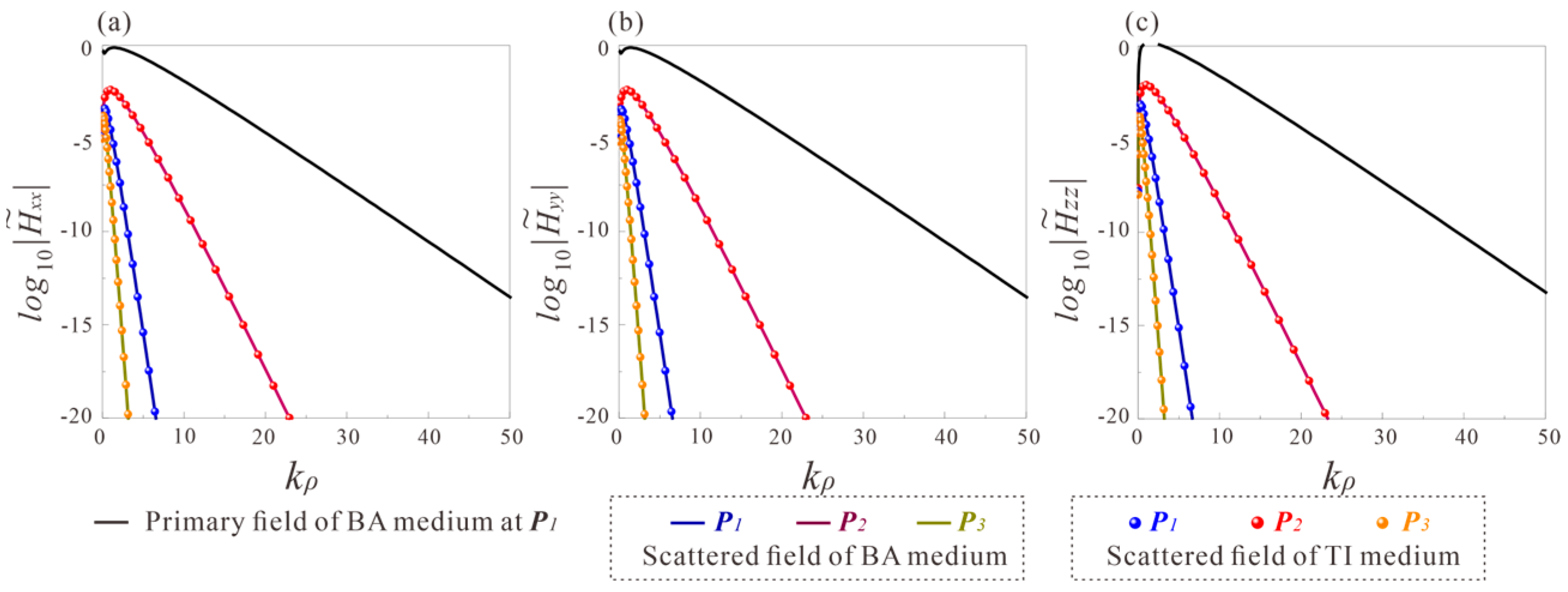
In order to verify the feasibility of the approximation, the magnetic dipole source and the three receiver points P1, P2 and P3 are placed at the positions shown in Figure 7. The convergence of the spectral primary field and the spectral scattered field of coaxial and coplanar components at point P1 are represented by the black and blue solid lines in Figure 9a–c, respectively. It can be noticed that the spectral scattered field converges rapidly and contributes a smaller percentage, which allows the spectral scattered fields to be approximated without compromising the calculation accuracy of the total field. The blue scatter plots in Figure 9a–c show the spectral scattered field convergence at P1 in the equivalent TI model for the coaxial and coplanar components by the equivalent formulae proposed in Section 3.3. It can be observed that the convergence process of the spectral scattered fields in the BA model overlaps with the equivalent TI model, confirming the feasibility of the approximation method. In addition, the approximate effect of the spectral scattered fields at P2 and P3 is also given in Figure 9a–c, which further verifies the applicability of the approximation method.

4.3. Best Approximation Model Analysis

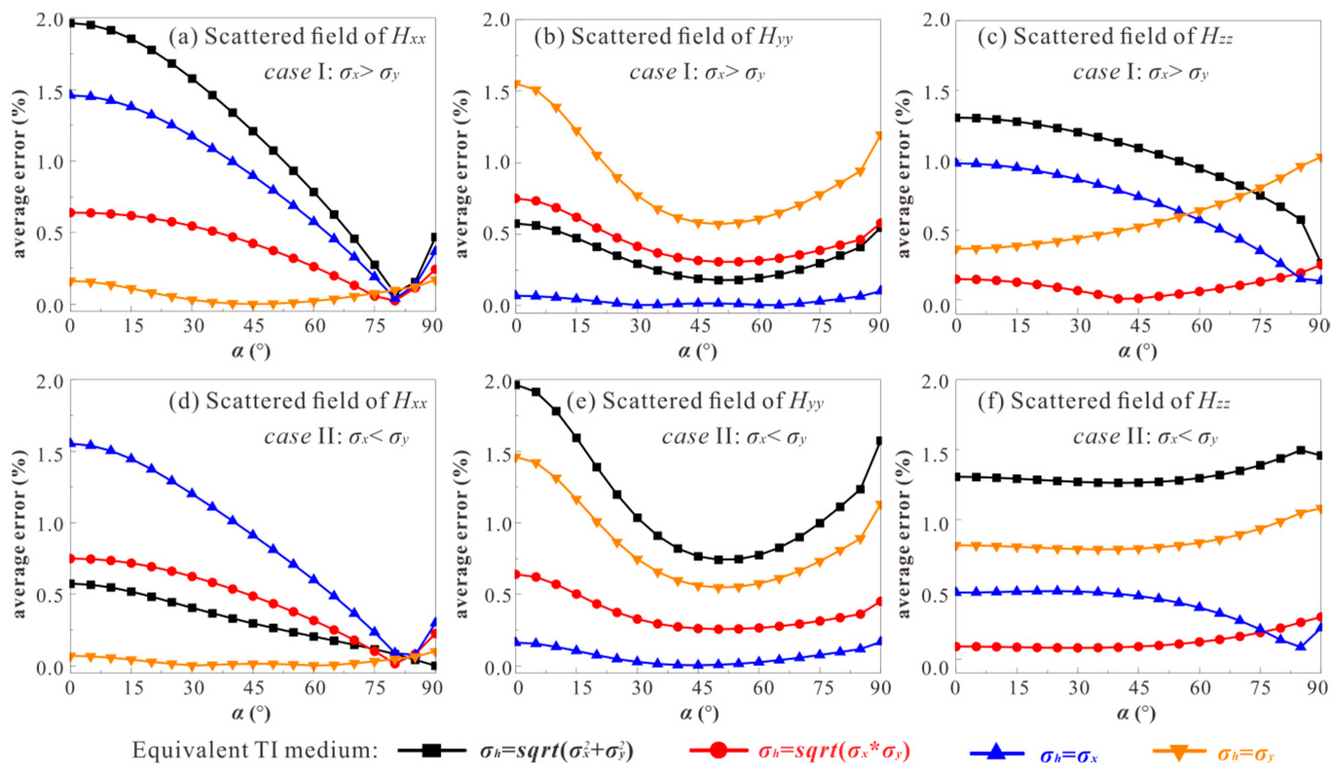
Generally, azimuthal angle effects are neglected in layered media, resulting in only five magnetic components (Hxx, Hyy, Hzz, Hxz and Hzx) exhibiting non-zero responses. The optimal construction of the equivalent TI medium of coaxial and coplanar components is given by analyzing the convergence of spectral primary fields in the previous sections. In order to verify whether these TI media can still obtain the best results when approximating the scattered fields, an error analysis is performed using the model shown in Figure 7. Figure 10 shows the average errors of the scattered fields of coaxial and coplanar components calculated by approximation and the MAPM algorithm in the model shown in Figure 7 under different dipping wells. Two BA cases, σx > σy ([σx, σy, σz] = [0.25, 0.1111, 0.0667] S/m) and σx < σy ([σx, σy, σz] = [0.1111, 0.25, 0.0667] S/m) are used in this example. It can be observed that the best approximation effect of Hxx can be obtained by σh = σy, which is consistent with the analysis results in Section 3.3. The same conclusion can be reached through the analysis of Hyy and Hzz. This illustrates that the optimal construction of the spectral primary field is also applicable to the approximation of the spectral scattered fields.
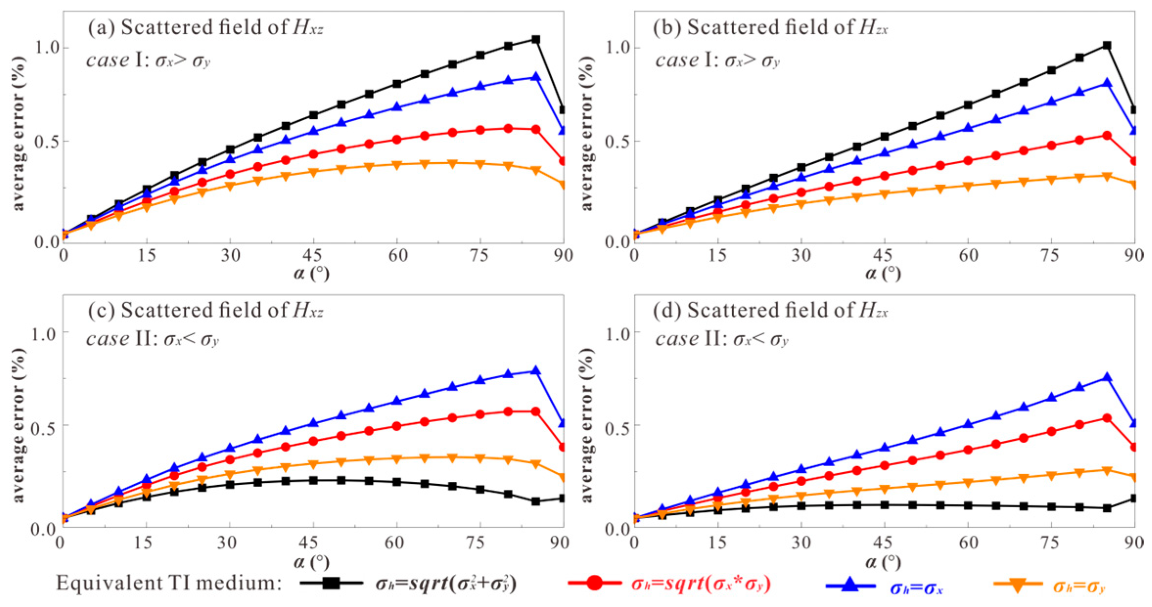
Analogous to the coaxial and coplanar components, approximate formulae are available to calculate the scattered fields for the cross magnetic components (Hxz and Hzx). Figure 11 shows the average errors of the cross components scattered fields under the same simulation conditions as in Figure 10. For the case of σx > σy, the most accurate approximation of the scattered field for the Hxz and Hzx components can be obtained by using the σh = σy for any dipping wells. In contrast, the σh = sqrt (σx* σy) method can obtain the optimal equivalent TI medium model for the Hxz and Hzx components for the case of σx < σy. In summary, Table 2 shows the optimal construction of the equivalent TI model used to calculate the scattered fields for coaxial, coplanar and cross magnetic components.

5. Numerical Examples

5.1. Accuracy Analysis

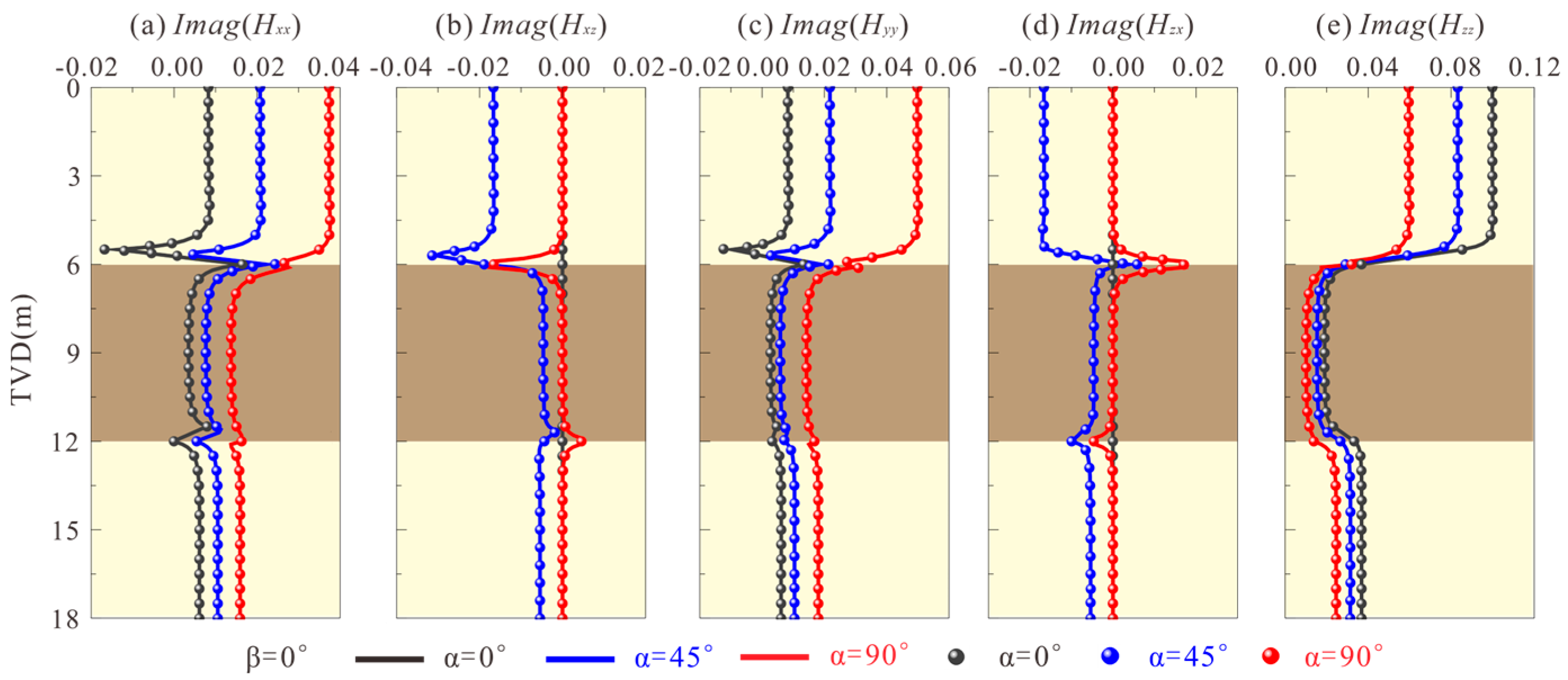
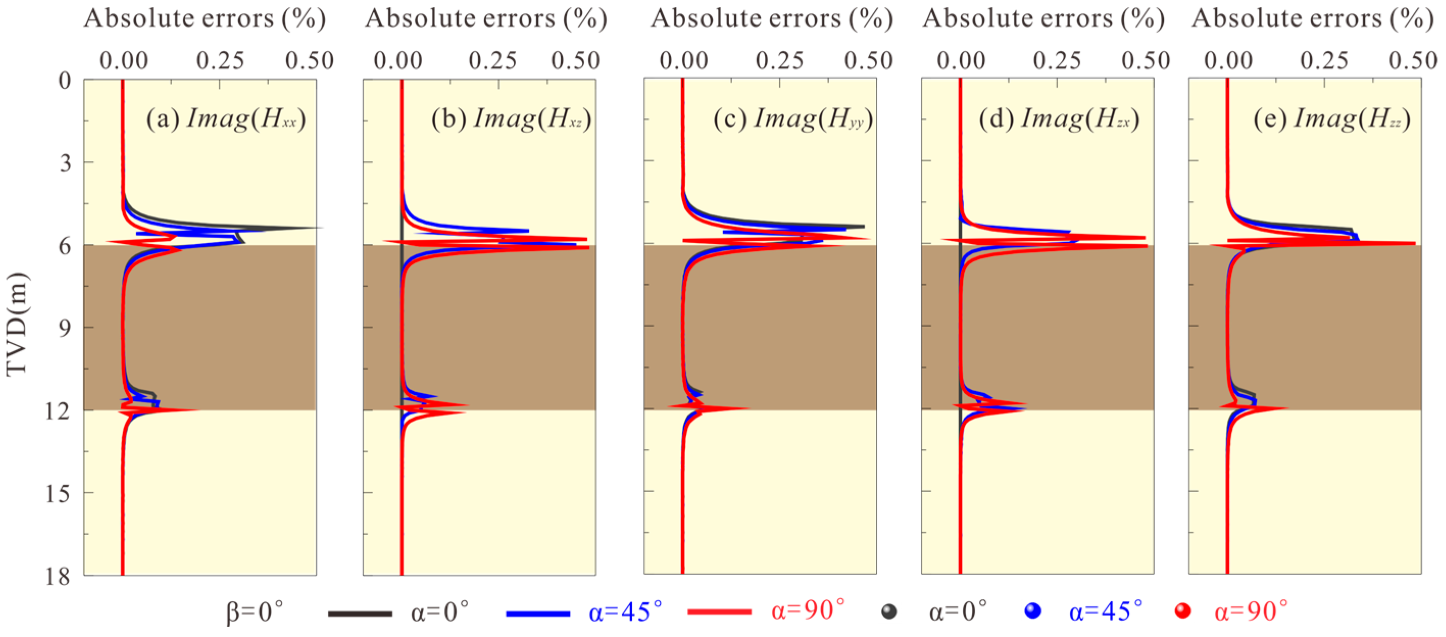
In order to verify the accuracy of the approximation method, the TIL response of the model in Figure 7 was calculated. Assuming the operating frequency of the TIL tool is 100 kHz and the source spacing is 0.8 m, Figure 12a–e shows the imaginary part of the magnetic components calculated by utilizing the equivalent TI medium and BA medium in different dipping angles when β = 0°. In Figure 12, the solid lines represent the calculated results of the magnetic components of BA medium, and the dotted lines represent the magnetic components results obtained after calculating the scattered field using the equivalent TI medium. Obviously, the results of the two models coincide with each other, which proves the accuracy of the approximation method. Figure 13a–e further illustrates the absolute errors calculated in Figure 12. It can be observed that the maximum absolute error of each magnetic component approximation is less than 0.5%, and the error mainly concentrated at the interface.
To further verify the applicability of the approximation method, Figure 14 shows the simulation results under different azimuth angles when the α = 80°. It can be observed that the approximation is still effective. Table 3 and Table 4 show the comparison of simulation speed and calculation accuracy of each component response between the MAPM and approximation algorithms in different dipping and azimuth angles. In this example, the specific parameters of the computing platform used are as follows, the operating system is Windows 10 64 bit Professional 21H2, the CPU is an Intel (R) Core (TM) i9-9900, and the memory capacity is 16 GB. The simulation speed of scattered fields can be increased by more than 30 times utilizing the approximation.

5.2. Applicability Analysis

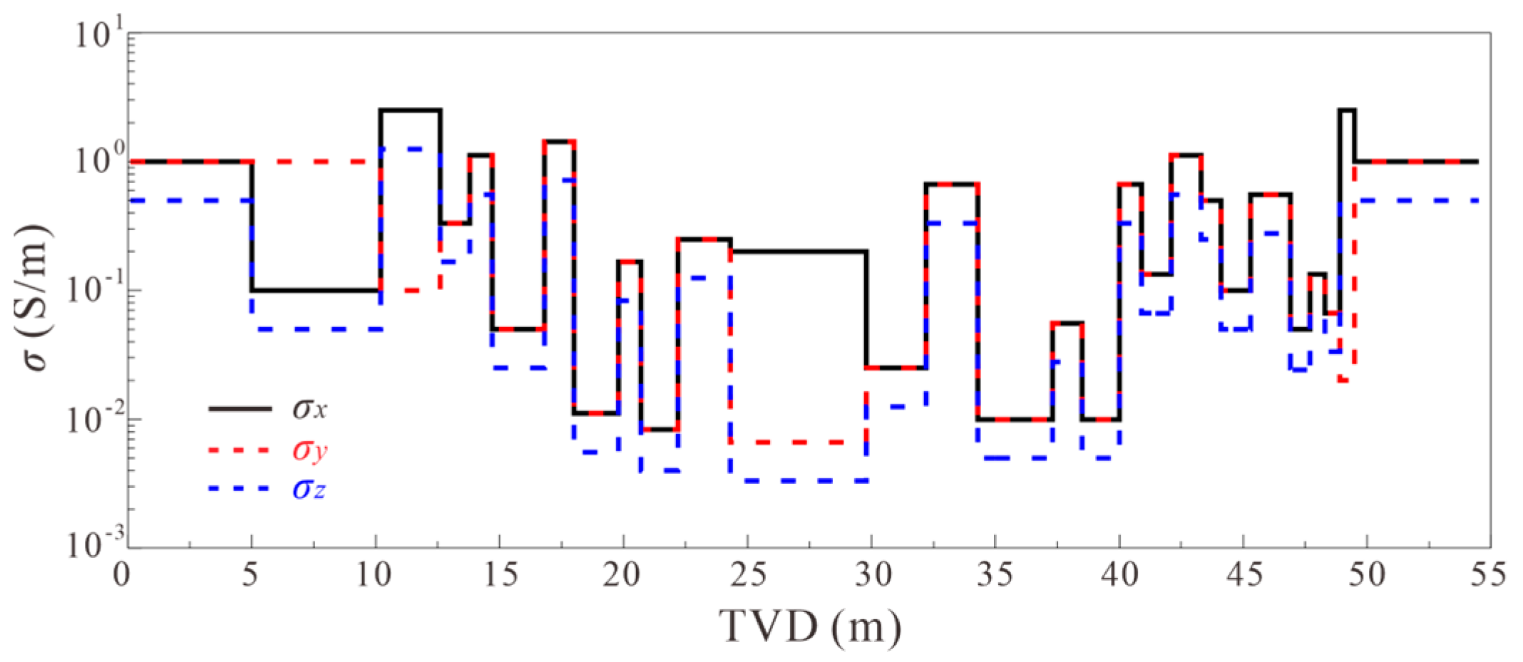
To verify the applicability and stability of the new forward modeling method, the Oklahoma model with BA was established, as shown in Figure 15. The thickness of the model ranges from 0.6 m to 5.5 m, including high and low resistance layers, and has different cases of BA. Figure 16 shows the TIL responses of coaxial, coplanar and cross magnetic components in the Oklahoma model with different frequencies using the MAPM method and approximation method. In this example, the dipping angle is 85° and the spacing is 1.0 m. It can be found that the approximation is applicable to arbitrary cases of formation and tool parameter conditions. The following conclusions can be drawn by analyzing the following: (I) when the frequency increases, each component signal becomes more sensitive to conductivity changes; (II) when σx > σy, each component curve exhibits the greatest separation, indicating a stronger influence of formation conductivity in the x-direction; (III) within the HZ well, the responses of cross components are zero in thick layers, and the influence of anisotropy is mainly reflected at the boundaries, while the responses of σ a x z and σ a z x have opposite patterns; and (IV) variations in horizontal anisotropy result in significant differences in coplanar component responses, while coaxial components are minimally affected. Overall, the different component responses show different sensitivities to different cases of BA, providing an opportunity to accurately characterize formation anisotropy.

6. Discussion

This paper introduces a fast and novel forward modeling algorithm for TIL in layered BA formations. The proposed method employs a two-level singularity subtraction technique for the rapid computation of spectral primary fields. Additionally, a concise recursive method (MAPM) and a fast approximation method are developed for the calculation of spectral scattered fields. This method significantly improves the forward modeling speed of TIL responses in layered BA media. However, it also has some limitations, as outlined below:

6.1. Advantages

  • The new approximation method is at least two orders of magnitude faster than the current modeling approach while maintaining a computational precision error within 0.5% after processing the primary and scattered fields, making real-time data processing possible.
  • The new approximation method is highly applicable to a wide range of formation conditions (including dip angle, thickness, and anisotropy) and tool parameters (such as frequency and spacing).
  • In addition to the approximation method, this paper also presents a concise and stable MAPM algorithm for the rigorous solution of scattered fields in layered BA media. This algorithm can be extended to more complex anisotropic models, such as cross anisotropy, full anisotropy.

6.2. Limits

  • The approximation method is currently applicable only to layered BA formations and is not yet suitable for more complex anisotropic cases, such as cross anisotropy and full anisotropy. Additionally, the method is designed for actual formations where the coefficient of horizontal anisotropy is small due to formation development and depositional features. As a result, it may not be applicable to anisotropic models in other fields.
  • The coil system of commercial TIL tools is typically designed with a single transmitter and two receivers. Due to the varying distances between the transmitting coil and the two receiving coils, it is necessary to separately approximate the formations at the locations of the two coils during the measurement process, making the procedure quite complex.

7. Conclusions

A fast and novel forward modeling algorithm of TIL in layered BA formation is presented in this paper. The two-level singularity subtraction on the primary fields has greatly narrowed the integral range and reduced the computational complexity. The first-level subtraction scheme works well in HA/HZ wells, whereas it is inapplicable to low deviated wells. By contrast, the second-level subtraction scheme can not only accommodate wells with arbitrary dipping angles, but also improves the convergence of spectral fields by four orders of magnitude.
The MAPM algorithm is concise and stable and can accurately calculate the spectral scattered fields for a layered BA medium with any thickness and arbitrary dipping wells. The optimal construction of the equivalent TI model is defined to approximate the scattered fields of coaxial, coplanar and cross components. The optimal construction formulae corresponding to Hxx, Hyy and Hzz are σh = σy, σh = σx and σh = sqrt (σx* σy) for the any BA cases, respectively. For the case of σx > σy, Hxz and Hzx can be most accurately approximated by σh = σy. Otherwise, their optimal construction formula is σh = sqrt ( σ x 2 + σ y 2 ).
Numerical examples demonstrate that the new simulation method is at least two orders of magnitude faster than the current modeling approach while maintaining computational precision error within 0.5% after processing the primary and scattered fields. Meanwhile, the new method has good performance in any formation conditions and tool parameters, which can meet the requirements of real time data processing. In the future, we will try to extend the fast computation method to the full anisotropic formations to realize the fast forward and inversion of TIL in the full anisotropic formations.

Author Contributions

Conceptualization, P.Q. and L.W.; methodology, P.Q.; validation, X.Y.; formal analysis, P.Q. and L.W.; investigation, X.Y. and S.D.; resources, L.W. and S.D.; data curation, P.Q.; writing—original draft preparation, P.Q. and L.W.; writing—review and editing, P.Q. and L.W.; visualization, P.Q.; supervision, L.W.; project administration, L.W.; funding acquisition, L.W., X.Y., and S.D. All authors have read and agreed to the published version of the manuscript.

Funding

This research was funded by the Science and Technology Innovation Project of Laoshan Laboratory, Grant number LSKJ202203407; the National Natural Science Foundation of China, Grant number U23B2086, 41904109 and 42204121; the National Natural Science Foundation of Shandong Province, Grant number ZR2023MD053; the Fundamental Research Funds for the Central Universities under Grant 21CX06005A and Grant 22CX01001A.

Data Availability Statement

The original contributions presented in the study are included in the article, further inquiries can be directed to the corresponding author.

Conflicts of Interest

Author Xiyong Yuan was employed by the company Sinopec Matrix Corporation. The remaining authors declare that the research was conducted in the absence of any commercial or financial relationships that could be construed as a potential conflict of interest.

References

  1. Anderson, B.I.; Barber, T.D.; Luling, M.G. The Response of Induction Tools to Dipping, Anisotropic Formations. In Proceedings of the Transactions of the SPWLA 36th Annual Logging Symposium Paper D, Paris, France, 26–29 June 1995. [Google Scholar]
  2. Gao, L.; Gianzero, S.; Kennedy, D.; SanMartin, L. The Response of a Triaxial Induction Sonde in a Biaxial Anisotropy Medium. Petrophysics 2002, 43, 172–184. [Google Scholar]
  3. Kang, Z.M.; Zhang, Y.; Hou, B.B.; Chen, G.; Hao, X.; Qin, H.; Qin, W. Using the Multi-component Induction Logging Data to Evaluate the Geometric Parameters of the Hydraulic Fracture. J. Geophys. Eng. 2022, 19, 1163–1179. [Google Scholar] [CrossRef]
  4. Hagiwara, T. Apparent Dip and Apparent Anisotropy from Multifrequency Triaxial Induction Measurements. Geophysics 2011, 76, F1–F13. [Google Scholar] [CrossRef]
  5. Fang, L.Q.; Bai, Y.X.; Guo, S.Y.; Liu, X.; Tang, S.; Li, X.; Xiao, J. Anisotropy Evaluation and Interface Detection Based on 3D Holographic Azimuthal Electromagnetic Resistivity Logging Instrument. J. Geophys. Eng. 2023, 20, 763–773. [Google Scholar] [CrossRef]
  6. Wu, Z.G.; Li, H.; Yue, X.Z. 2.5-Dimensional modeling of EM logging-while-drilling tool in anisotropic medium on a Lebedev grid. Pet. Sci. 2023, 20, 249–260. [Google Scholar] [CrossRef]
  7. Kriegshauser, B.; Fanini, O.; Forgang, S.; Itskovich, G.; Rabinovich, M.; Tabarovsky, L.; Vd Horst, J. A New Multicomponent Induction Logging Tool to Resolve Anisotropic Formations. In Proceedings of the SPWLA 41st Annual Logging Symposium, Dallas, TX, USA, 4–7 June 2000. [Google Scholar]
  8. Georgi, D.; Schoen, J.; Rabinovich, M. Biaxial Anisotropy: Its Occurrence and Measurement with Multicomponent Induction Tools. In Proceedings of the SPE Annual Technical Conference and Exhibition, USE Society of Petroleum Engineers, Denver, CO, USA, 21–24 September 2008. [Google Scholar]
  9. Michael, Z.; David, K.; Ertan, P. Foundations of Tensor Induction Well-Logging. Petrophysics 2001, 42, 588–610. [Google Scholar]
  10. Davydycheva, S.; Wang, T. A Fast Modeling Method to Solve Maxwell’s Equations in 1D Layered Biaxial Anisotropic Medium. Geophysics 2011, 76, F293–F302. [Google Scholar] [CrossRef]
  11. Cheryauka, A.B.; Zhdanov, M.S. Focusing Inversion of Tensor Induction Logging Data in Anisotropic Formations and Deviated Well. In Proceedings of the 71st Annual International Meeting, SEG, Expanded Abstracts, San Antonio, TX, USA, 9–14 September 2001; pp. 357–360. [Google Scholar]
  12. Kerry, K. Is the Fast Hankel Transform Faster Than Quadrature? Geophysics 2012, 77, F21–F30. [Google Scholar]
  13. Wang, L.; Qiao, P.; Zhao, W.N. A New Propagator Matrix Algorithm to Compute Electromagnetic Fields in Multilayered Formations with Full Anisotropy. IEEE Trans. Geosci. Remote Sens. 2023, 61, 1–11. [Google Scholar] [CrossRef]
  14. Chen, J.F. A Semianalytical Finite Element Analysis of Electromagnetic Propagation Stratified Media. Microw. Opt. Technol. Lett. 2015, 57, 15–18. [Google Scholar] [CrossRef]
  15. Hu, Y.Y.; Sun, Q.T. Modeling of triaxial induction logging responses in multilayered anisotropic formations. Geophysics 2021, 86, E305–E314. [Google Scholar] [CrossRef]
  16. Kang, Z.Z.; Wang, H.N.; Yin, C.C. Semi-Analytic Sensitivity of the MCIL Responses in Homogeneous Biaxial Anisotropic Media. IEEE Geosci. Remote Sens. Lett. 2022, 19, 1–5. [Google Scholar] [CrossRef]
  17. Zhou, Y.G.; Wang, L.J.; Ren, Q.; Liang, B.; Liu, Q.H. Simulation of Electromagnetic Waves in Magnetized Cold Plasma by a Novel BZT-DGTD Method. IEEE Trans. Antennas Propag. 2023, 71, 9233–9244. [Google Scholar] [CrossRef]
  18. Kong, J.A. Electromagnetic Fields Due to Dipole Antennas Over Stratified Anisotropic Media. Geophysics 1972, 37, 985–996. [Google Scholar] [CrossRef]
  19. Chew, W.C. Waves and Fields in Inhomogeneous Media; IEEE Press: New York, NY, USA, 1995. [Google Scholar]
  20. Løseth, L.; Ursin, B. Electromagnetic Fields in Planarly Layered Anisotropic Media. Geophys. J. Int. 2007, 170, 44–80. [Google Scholar] [CrossRef]
  21. Yuan, N.; Nie, X.C.; Liu, R.; Qiu, C.W. Simulation of Full Responses of a Triaxial Induction Tool in a Homogeneous Biaxial Anisotropic Formation. Geophysics 2010, 75, E101–E114. [Google Scholar] [CrossRef]
  22. Wang, G.L.; Barber, T.; Wu, P.; Allen, D.; Abubakar, A. Fast Inversion of Triaxial Induction Data in Dipping Crossbedded Formations. Geophysics 2017, 82, 31–45. [Google Scholar] [CrossRef]
  23. Hong, D.C.; Li, N.; Han, W.; Zhan, Q.; Zeyde, K.; Liu, Q.H. An Analytic Algorithm for Dipole Electromagnetic Field in Fully Anisotropic Planar-Stratified Media. IEEE Trans. Geosci. Remote Sens. 2021, 59, 9120–9131. [Google Scholar] [CrossRef]
  24. Guptasarma, D.; Singh, B. New Digital Linear Filters for Hankel J0 and J1 Transforms. Geophys. Prospect. 1997, 45, 745–762. [Google Scholar] [CrossRef]
  25. Simsek, E.; Liu, Q.H.; Wei, B. Singularity Subtraction for Evaluation of Green’s Functions for Multilayer Media. IEEE Trans. Microw. Theory Techn. 2006, 54, 216–225. [Google Scholar] [CrossRef]
  26. Liu, T.L.; Xing, G.L.; Zhang, X.C. Electromagnetic Fields Computation of Planar-Distribution Sources in Anisotropic Planar-Stratified Media with an Equivalent Boundary Approach. IEEE Trans. Geosci. Remote Sens. 2024, 62, 1–13. [Google Scholar] [CrossRef]
  27. Hu, Y.Y.; Yuan, F.; Wang, D.Z.; Zhong, Y.; Liu, Q.H. Electromagnetic Waves in Multilayered Generalized Anisotropic Media. IEEE Trans. Geosci. Remote Sens. 2018, 56, 5758–5766. [Google Scholar] [CrossRef]
  28. Li, N.; Hong, D.C.; Han, W.; Liu, Q.H. An Analytic Algorithm for Electromagnetic Field in Planar-Stratified Biaxial Anisotropic Formation. IEEE Trans. Geosci. Remote Sens. 2020, 58, 1644–1653. [Google Scholar] [CrossRef]
  29. Deng, S.G.; Liu, T.L.; Wang, L. Analytical Solution of Multicomponent Induction Logging Response in Biaxial Anisotropy Medium. Chin. J. Geophys. 2020, 63, 362–373. (In Chinese) [Google Scholar]
  30. Wang, L.; Qiao, P.; Li, Z.Q. A New Semi-Analytical Algorithm for Rapid Simulation of Triaxial Electromagnetic Logging Responses in Multilayered Biaxial Anisotropic Formation. Geophysics 2023, 88, D115–D129. [Google Scholar] [CrossRef]
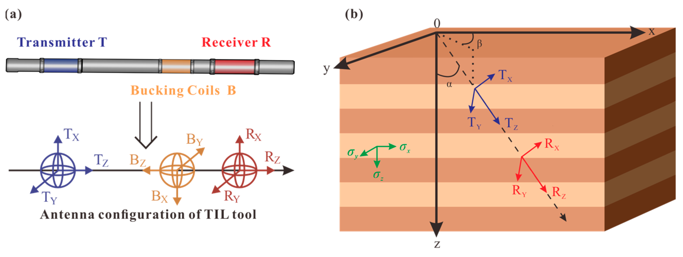
Figure 1. (a) Structure and antenna configuration of TIL tool. (b) Operation of triaxial induction logging tool in layered media.
Remotesensing 16 03076 g001
Figure 2. The convergence of the spectral coaxial magnetic component through the first−level subtraction at varying dip angles, (a) α = 0°; (b) α = 30°; (c) α = 45°; (d) α = 60°; (e) α = 75°; and (f) α = 90°.
Remotesensing 16 03076 g002
Figure 3. The convergence of spectral coaxial magnetic component through two−level subtraction at different dip angles, (a) α = 0°; (b) α = 30°; (c) α = 45°; (d) α = 60°; (e) α = 75°; and (f) α = 90°.
Remotesensing 16 03076 g003
Figure 4. The subtracted convergence of the coaxial and coplanar magnetic components using different equivalent TI models in HZ well with the operation frequency of 10 kHz and a spacing of 0.5 m, (a) H ˜ x x in case I; (b) H ˜ y y in case I; (c) H ˜ z z in case I; (d) H ˜ x x in case II; (e) H ˜ y y in case II; (f) H ˜ z z in case II.
Remotesensing 16 03076 g004
Figure 5. The subtracted convergence of the coaxial and coplanar magnetic components using different equivalent TI models in HZ wells, where the settings of formation conductivity and tool parameters are identical to Figure 4, (a) H ˜ x x in case I; in case I; (b) H ˜ y y in case I; (c) H ˜ z z in case I; (d) H ˜ x x in case II; (e) H ˜ y y in case II; (f) H ˜ z z in case II.
Remotesensing 16 03076 g005
Figure 6. Propagation of upgoing and downgoing waves in layered media.
Remotesensing 16 03076 g006
Figure 7. A three-layer BA formation model.
Remotesensing 16 03076 g007
Figure 8. The responses of TIL in the layered BA model with different dipping angles: (a) three-layer model; (b) σ a x x ; (c) σ a x z ; (d) σ a y y ; (e) σ a z x and (f) σ a z z .
Remotesensing 16 03076 g008
Figure 9. Convergence of spectral primary and scattered fields of coaxial and coplanar magnetic components, (a) H ˜ x x ; (b) H ˜ y y ; (c) H ˜ z z .
Remotesensing 16 03076 g009
Figure 10. The average error of coaxial and coplanar components scattered fields calculated by the approximation and the MAPM method in different dipping wells, (a) H ˜ x x in case I; (b) H ˜ y y in case I; (c) H ˜ z z in case I; (d) H ˜ x x in case II; (e) H ˜ y y in case II; (f) H ˜ z z in case II.
Remotesensing 16 03076 g010
Figure 11. The average error of cross components scattered fields calculated by the approximation and the MAPM method in different dipping wells, (a) H ˜ x z in case I; (b) H ˜ z x in case I; (c) H ˜ x z in case I; (d) H ˜ z x in case II.
Remotesensing 16 03076 g011
Figure 12. The imaginary part of the magnetic components using the MAPM method and approximation method in different dip angles: (a) Imag(Hxx); (b) Imag(Hxz); (c) Imag(Hyy); (d) Imag(Hzx); and (e) Imag(Hzz).
Remotesensing 16 03076 g012
Figure 13. The absolute errors of the imaginary magnetic components between the MAPM method and approximation method in different dip angles: (a) Imag(Hxx); (b) Imag(Hxz); (c) Imag(Hyy); (d) Imag(Hzx); and (e) Imag(Hzz).
Remotesensing 16 03076 g013
Figure 14. The imaginary part of magnetic components using the MAPM method and the approximation method in different azimuth angles: (a) Imag(Hxx); (b) Imag(Hxz); (c) Imag(Hyy); (d) Imag(Hzx); and (e) Imag(Hzz).
Remotesensing 16 03076 g014
Figure 15. The Oklahoma model with BA.
Remotesensing 16 03076 g015
Figure 16. The TIL responses of coaxial, coplanar and cross magnetic components with different frequencies using the MAPM method and approximation method, (a) σ a x x ; (b) σ a x z ; (c) σ a y y ; (d) σ a z x ; (e) σ a z z .
Remotesensing 16 03076 g016
Table 1. Symmetry of spectral magnetic components at four quadrants.
Components H x x H y y H z z H x y , H y x H x z , H z x H y z , H z y
Quadrants
1st +1+1+1+1+1+1
2nd −1−1−1+1+1−1
3rd +1+1+1+1−1−1
4th −1−1−1+1−1+1
Table 2. Optimal construction of the equivalent TI model for different magnetic components.
Components H x x H y y H z z H x z , H z x
Cases
σx > σyσh = σyσh = σx σ h = σ x * σ y σh = σy
σx < σy σ h = σ x 2 + σ y 2
Table 3. Calculation speed comparison and average errors of each component response between the MAPM and approximation algorithms in different dipping and azimuth angles.
α, β (°)Average Errors (%)Relative Time Cost (MAPM (s))Relative Time Cost (Approximation(s))Speed-Up Factor
σ a x x σ a y y σ a z z σ a x z σ a z x
0, 00.2030.2120.1980.2210.2240.03210.000841.25
45, 00.2340.2310.2220.2620.2600.03820.001037.34
90, 00.2570.2480.2420.2770.2690.07390.002233.56
80, 300.2640.2520.2450.2790.2710.08580.002533.89
80, 450.2680.2570.2470.2800.2720.09370.002932.51
80, 750.2760.2670.2530.2840.2750.13090.004430.05
Table 4. The minimum errors and maximum errors of each component response between the MAPM and approximation algorithms in different dipping and azimuth angles.
α, β (°)Minimum Errors (%)Maximum Errors (%)
σ a x x σ a y y σ a z z σ a x z σ a z x σ a x x σ a y y σ a z z σ a x z σ a z x
0, 00.0220.0230.0220.0240.0240.4480.4680.4370.4880.495
45, 00.0250.0250.0240.0280.0280.4680.4620.4440.5240.52
90, 00.0280.0270.0260.0300.0290.5140.4960.4840.5540.538
80, 300.0280.0280.0270.0300.0290.5280.5040.490.5580.542
80, 450.0290.0280.0270.0300.0290.5360.5140.4940.560.544
80, 750.0300.0290.02750.0300.0290.5520.5340.5060.5680.551
Disclaimer/Publisher’s Note: The statements, opinions and data contained in all publications are solely those of the individual author(s) and contributor(s) and not of MDPI and/or the editor(s). MDPI and/or the editor(s) disclaim responsibility for any injury to people or property resulting from any ideas, methods, instructions or products referred to in the content.