Article

Enhancing User Localization with an Integrated Sensing and Communication (ISAC) System: An Experimental UAV Search-and-Rescue Use Case

by
Stefano Moro
*,
Francesco Linsalata
,
Marco Manzoni
,
Maurizio Magarini
and
Stefano Tebaldini
Department of Electronics, Information and Bioengineering, Politecnico di Milano, 20133 Milan, Italy
*
Author to whom correspondence should be addressed.
Remote Sens. 2024, 16(16), 3031; https://doi.org/10.3390/rs16163031
Submission received: 14 June 2024 / Revised: 13 August 2024 / Accepted: 16 August 2024 / Published: 18 August 2024
(This article belongs to the Section Environmental Remote Sensing)

Abstract

:
This paper explores the potential of an Integrated Sensing and Communication (ISAC) system to enhance search-and-rescue operations. While prior research has explored ISAC capabilities in Unmanned Aerial Vehicles (UAVs), our study focuses on addressing the specific challenges posed by modern communication standards (e.g., power, frequency, and bandwidth limitations) in the context of search-and-rescue missions. The paper details effective methods for processing echoed signals generated by downlink transmissions and evaluates key performance indicators, including Noise Equivalent Sigma Zero (NESZ) and channel capacity. Additionally, we utilize synchronization uplink signals transmitted by User Equipment (UE) to improve target detection and classification of possible victims by fusing SAR imagery with triangulation results from uplink signals. An experimental campaign validates the proposed setup by integrating SAR images of the environment with active localization results, both produced by a UAV equipped with a Software Defined Radio (SDR) payload. Our results demonstrate the system’s capability to detect and localize buried targets in avalanche scenarios, with localization errors ranging from centimeters to 10 m depending on environmental conditions. This successful integration highlights the practical applicability of our approach in challenging search-and-rescue missions.

1. Introduction

Traditionally, wireless communication and radar systems have operated independently, each with their unique hardware, waveforms, and objectives. Wireless communication systems are primarily designed for information transmission, while radar systems focus on environmental sensing. However, the advent of sixth-generation (6G) cellular networks offers a new perspective, merging sensing and communication into Integrated Sensing and Communication (ISAC) systems [1,2]. This convergence brings forth significant challenges, particularly in integrating radar sensing capabilities within communication systems. Integrating communication signals into radar systems involves embedding these signals into radar emissions, aiming to minimize interference. Previous research has explored methods such as selecting radar waveforms that can simultaneously serve communication purposes [3,4]. While radar systems benefit from their long-range capabilities, their capacity is often limited by the inherent constraints of radar waveforms. Conversely, in communication-centric systems, radar sensing typically plays a secondary role. This approach involves optimizing the allocation of time-frequency resources using established waveforms like Orthogonal Frequency Division Multiplexing (OFDM) from 5G New Radio [5,6,7,8,9]. Researchers have developed power optimization techniques based on mutual information to determine the power allocation strategy for ISAC systems that prioritize radar and communication functionalities [10]. Information-theoretic metrics have been employed to design OFDM ISAC waveforms, optimizing for both communication and sensing channels [11,12].
In [13], the authors address the practical challenges of implementing delay and Doppler estimation using OFDM. They identify processing complexity and self-interference as the primary challenges but demonstrate the feasibility of range and Doppler imaging through experimental results. Waveform design optimization, considering timing, frequency, and power resource allocation, has been shown to improve target detection capabilities significantly [9]. However, one potential issue is the ambiguity function of the resulting waveform, which may obscure weak targets not considered during optimization. Innovations in ISAC systems include waveform design through beam pattern optimization, ensuring flexible design for both communication and sensing by configuring the spatial correlation of signals across transmitting antennas [14,15]. Super-resolution range and velocity estimators tailored for OFDM-based ISAC systems further enhance performance [6]. The COSMIC (Connectivity-Oriented Sensing Method for Imaging and Communication) waveform design technique is a significant advancement in this field, which achieves orthogonality through extended conditions rather than traditional multiplexing [16]. This method enables simultaneous environmental imaging and data communication, representing a significant breakthrough in Multiple Input-Multiple Output (MIMO) radar-communication technology.

1.1. Related Works on ISAC-Empowered UAVs

In recent years, significant advancements in Unmanned Aerial Vehicle (UAV) technology have revolutionized their utility across diverse domains [17]. These strides include enhancements in battery longevity, heightened reliability, sophisticated autonomous navigation software, and the adoption of lightweight materials [18]. The decreased cost of drones has further facilitated the proliferation of aerial networks, enabling continuous operations through coordinated flying and recharging maneuvers [19,20].
Among the diverse applications of UAVs, their pivotal role in search-and-rescue operations stands out, owing to their swift deployment, user-friendly operation, and adaptability during emergencies [21]. Equipped with an array of sensors, including optical and thermal cameras, LiDARs, and radars, UAVs are well equipped for various rescue missions. Radar technology, in particular, holds prominence for its capability to emit electromagnetic (EM) waves into the ground, facilitating the detection of individuals buried under debris or snow, an invaluable asset following natural disasters like earthquakes or avalanches [22]. However, traditional radar systems on UAVs often operate independently of communication systems, limiting their potential for real-time information sharing and coordinated search efforts.
One notable system used for avalanche person retrieval comes from the Swedish company RECCO [23]. Their system comprises a lightweight metallic reflector integrated inside clothing and an active transceiver that can be manually handled or attached below a helicopter. The working principle is based on harmonic radar, where the illuminator transmits a specific waveform at 866.9 MHz, and the emission generated by the passive reflector is at twice the frequency of the transmitted one, 1733.8 MHz. This configuration enhances the Signal-to-Noise Ratio (SNR) of the reflection, aiding in distinguishing between clutter and a real buried person. The company advertises the system for a maximum detection range of 80 m through the air and 20 m through the snow. Professional rescue teams commonly utilize RECCO systems in major ski resorts. In [24], a case study reports the fundamental role of RECCO devices in rescuing two off-piste skiers in Spain. However, RECCO systems are passive and rely on the victim wearing a reflector, limiting their applicability in scenarios where individuals are not equipped with such devices.
Another possible solution for rescue teams is internationally standardized avalanche transceivers operating on the 457 kHz bandwidth. These handheld systems can operate in scan and beacon modes and are carried by professional hikers and skiers. The operational principle is more straightforward compared to the RECCO system, with a scanning range of approximately 30 m. Nonetheless, using this system can reduce mortality rates in avalanche incidents as documented in [25]. However, these transceivers require the victim to carry a transmitting beacon and rely on rescuers manually searching the area, which can be time-consuming and challenging in large or complex environments.
In this context, ISAC-ready UAVs can provide crucial wireless connectivity to rescuers in disaster-stricken or remote areas [26]. An example of a UAV-based emergency localization system is the SARDO system, presented in [27]. The system exploits an International Mobile Subscriber Identity (IMSI) catcher mounted on the UAV to communicate with a ground user. The IMSI catcher enables the UAV to scan the area for victims and localize them using Time of Flight distance measurements. The reported localization error for a single victim is less than 100 m. Nevertheless, such systems rely on the active participation of the user’s device, which might not be feasible in all emergency scenarios.
While UAVs have demonstrated resilience in operating under light rain and moderate winds, adverse weather conditions can significantly impact their performance and effectiveness. Heavy rainfall or snowfall can pose challenges to flight stability and navigation and lead to significant attenuation of the electromagnetic waves used for communication and sensing, potentially compromising the ability of the UAV to perform its mission [28]. The ISAC paradigm offers a comprehensive solution addressing radar-based sensing and communication requirements. By sharing spectrum or utilizing the same signal for communication and sensing tasks, ISAC technology optimizes resource allocation and enhances the capabilities of UAV-based systems. Moreover, [29] investigates the optimization of UAV trajectories to strengthen communication and sensing capabilities while considering power consumption. While ISAC has been explored across various domains, including IoT, 6G or UAV-aided coverage [17,19,21,30], its implementation for UAV-based Synthetic Aperture Radar (SAR) imaging to aid search-and-rescue operations remains an area that has not been studied extensively.
By contrast, this paper builds on the foundational concepts introduced in [31], where we laid the groundwork for this study. Here, we expand the localization concept by integrating a multiphase approach. Our objective is to demonstrate the effectiveness of an Integrated Sensing and Communication (ISAC) system for search-and-rescue operations, utilizing SAR imaging with a UAV as an aerial base station, combined with an active localization approach. Figure 1 illustrates the reference search-and-rescue scenario, where a UAV scans for avalanche victims in a snowy mountain area while simultaneously providing communication services to rescuers. This integrated approach represents a significant advancement beyond previous work, addressing the need for robust, real-time situational awareness and communication in challenging SAR environments.

1.2. Paper Contributions

The main contribution of the paper can be summarized as follows:
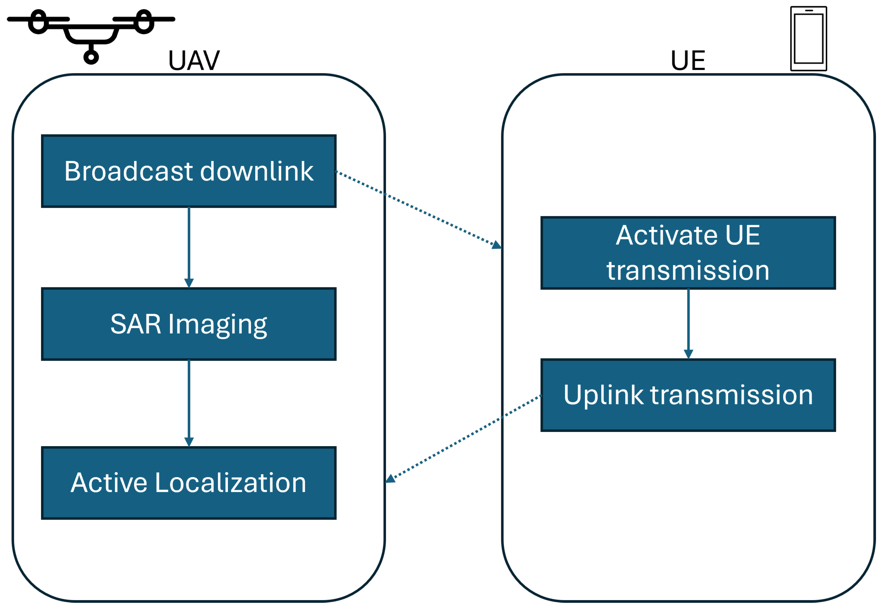
  • We validate the system’s capability to generate high-quality SAR imagery while adhering to modern communication standards. Specifically, we propose a two-phase localization procedure that merges results from both passive, which exploits downlink ISAC signal, and active methods, which are based on the uplink signal sent by the users during the synchronization phase.
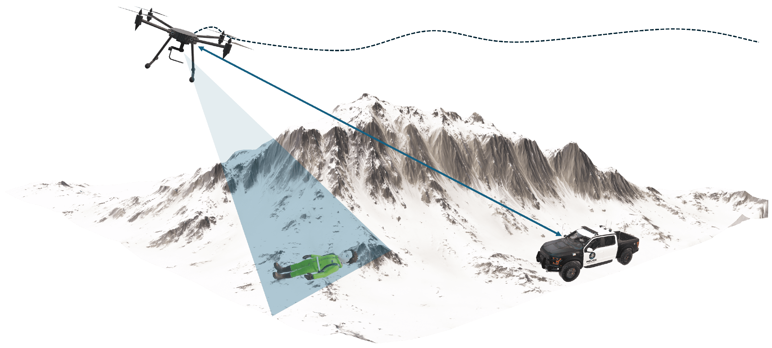
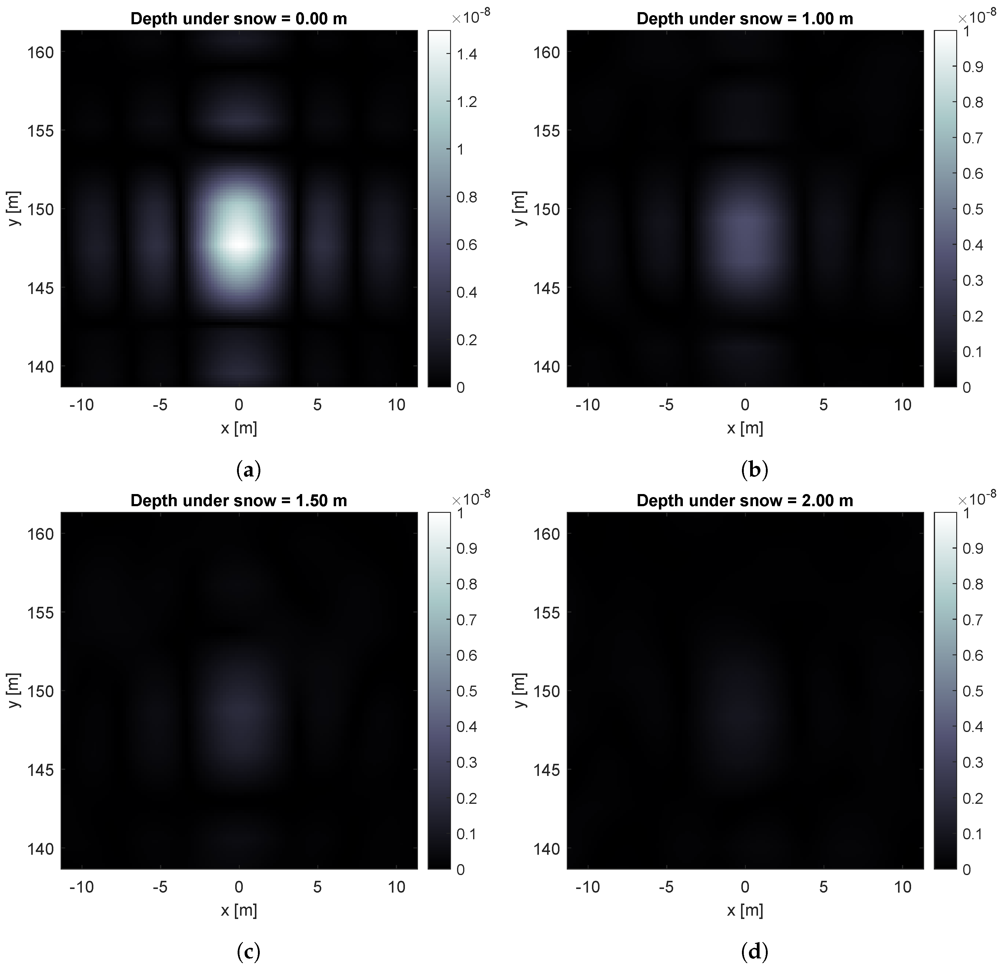
  • We focus on introducing a practical approach to speed up search-and-rescue operations by localizing and imaging buried targets in challenging scenarios, such as persons under snow after an avalanche.
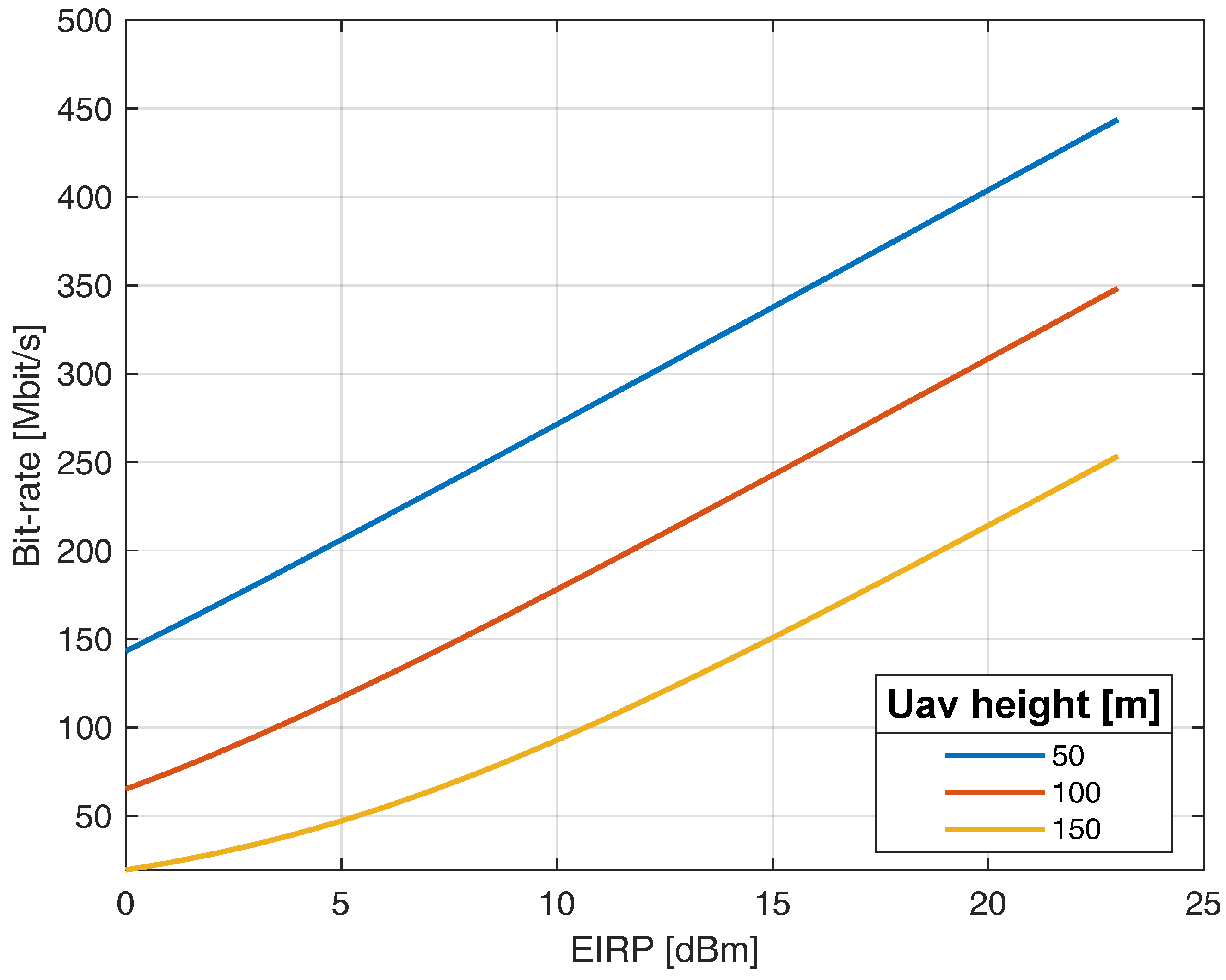
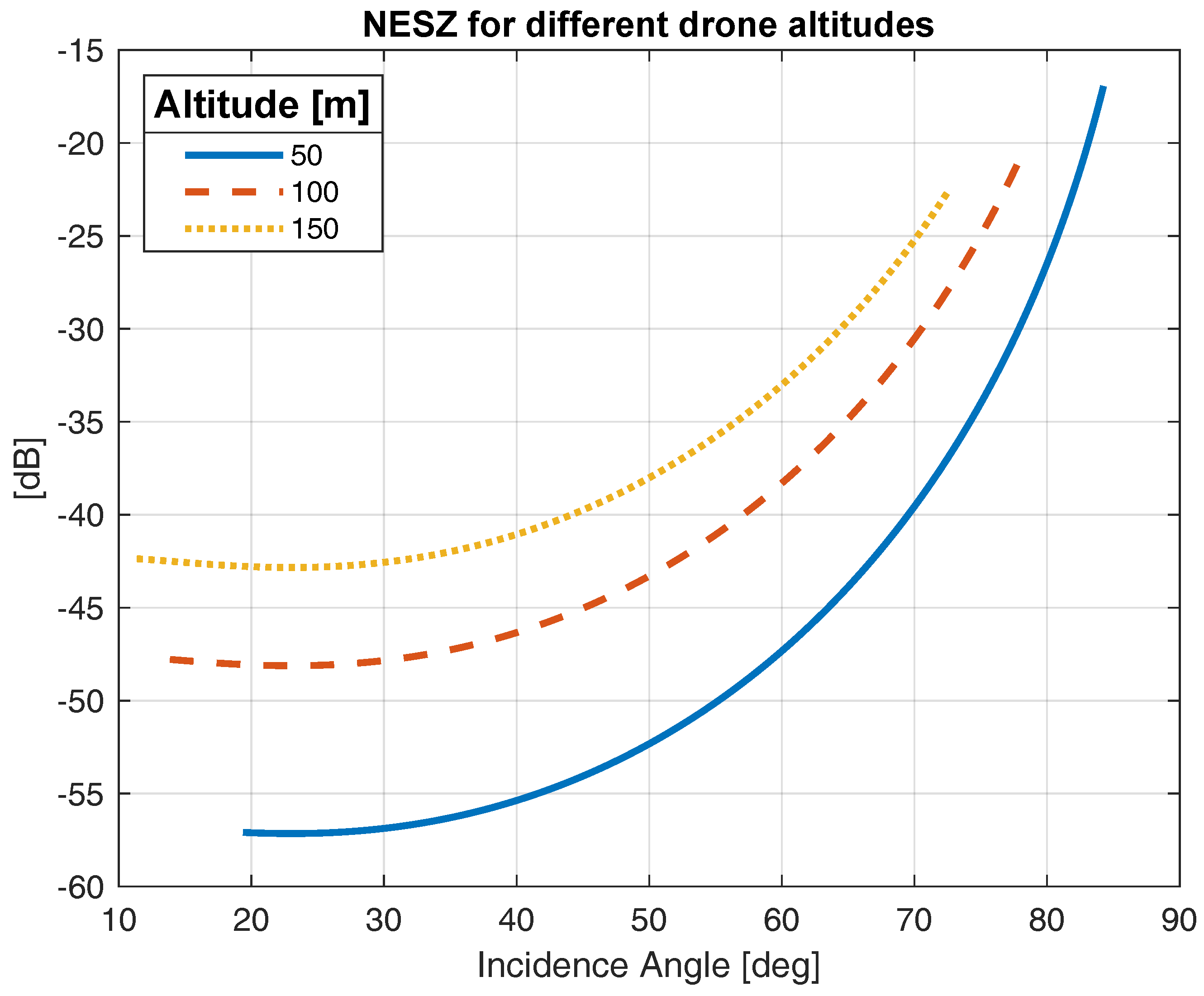
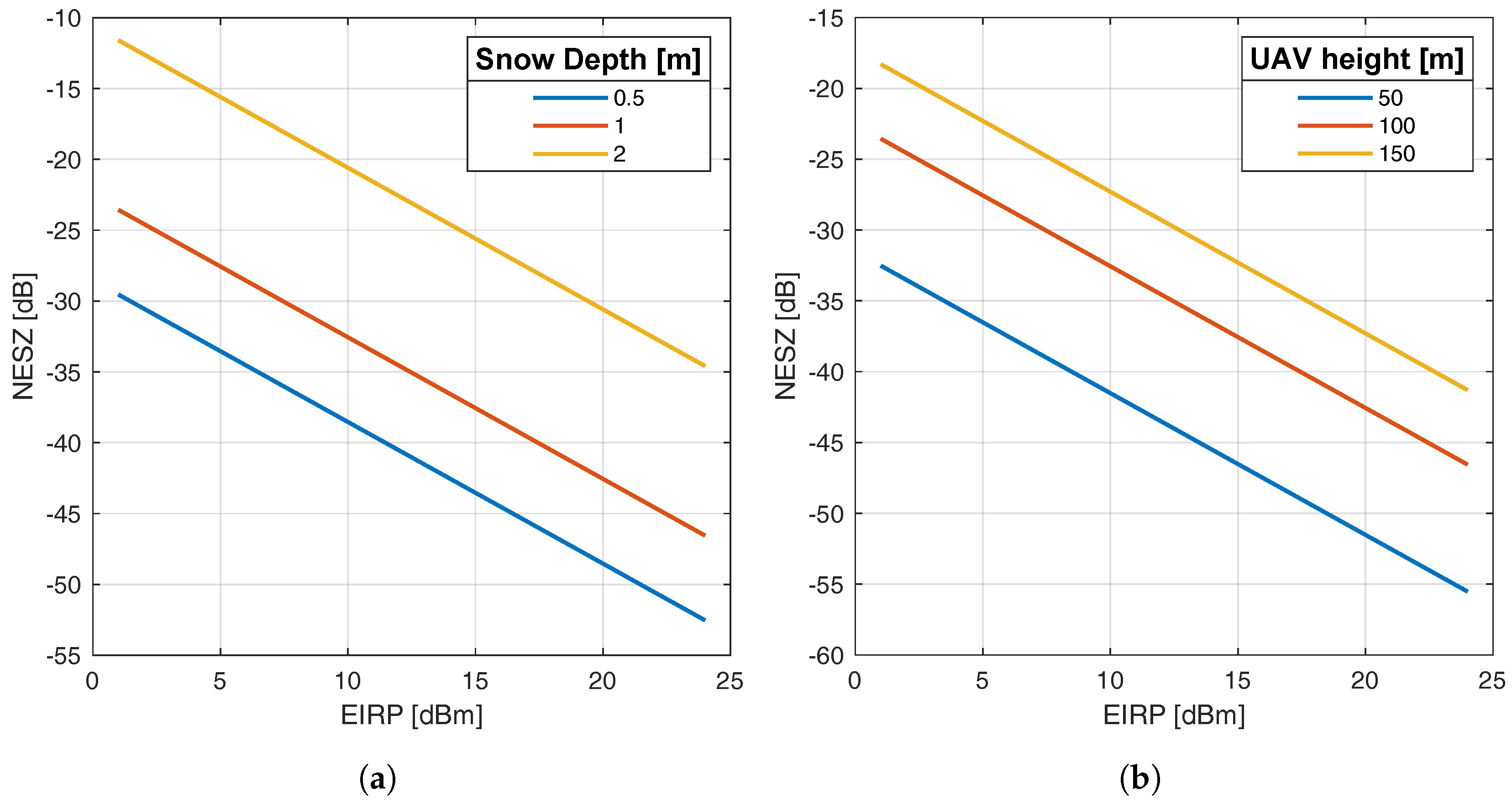
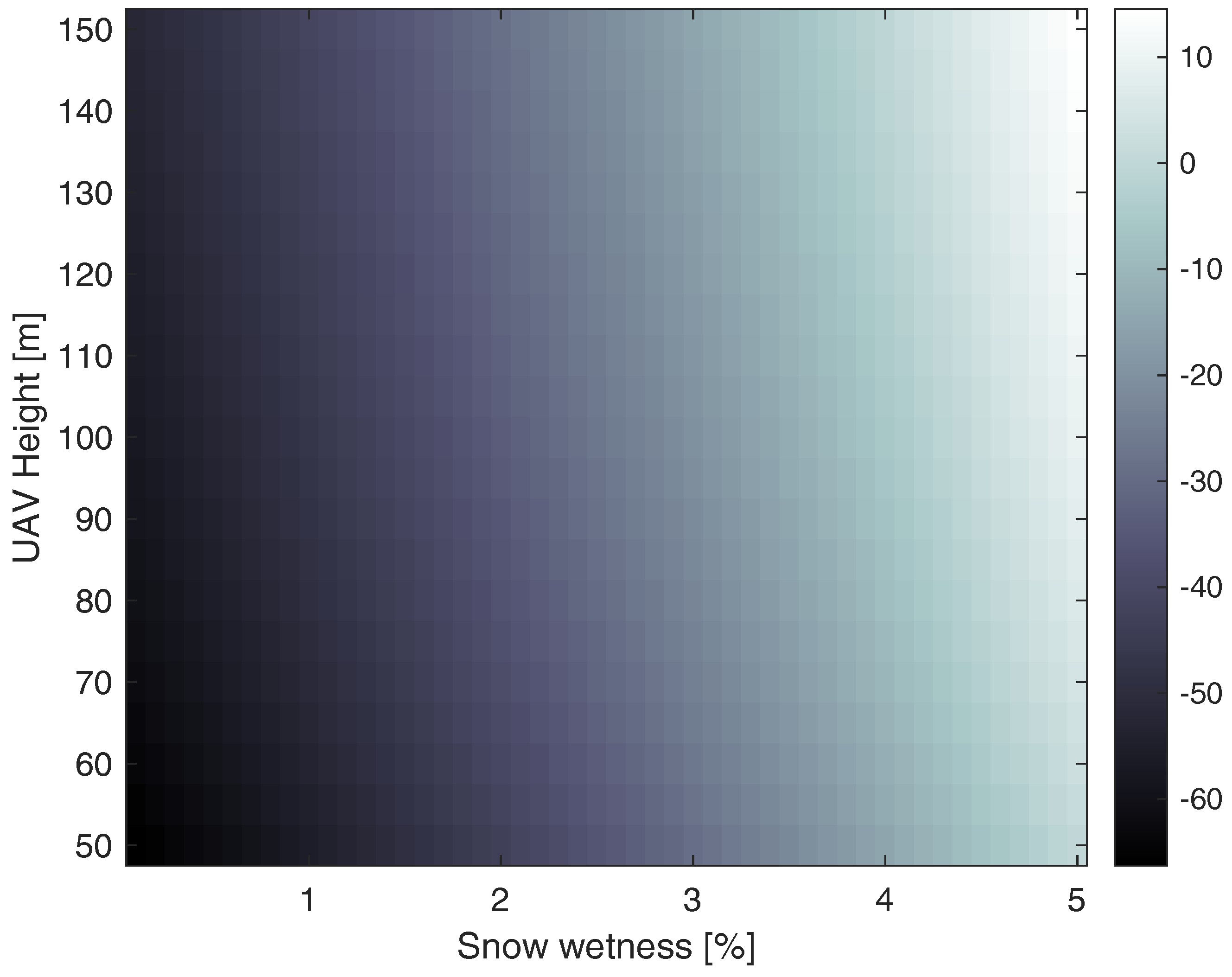
  • We provide exhaustive numerical simulations that demonstrate the system communication and sensing performance in different conditions, such as UAV altitude and snow depth. Moreover, our exploration includes various signal processing techniques and an analysis of key performance metrics, such as Noise Equivalent Sigma Zero (NESZ) and channel capacity, using the QUAsi Deterministic RadIo channel GenerAtor (QuaDRiGa).
  • We simulate the performance results of the Received Signal Strength Indicator (RSSI)-based localization of a ground RF transmitter. This applies to a scenario where a victim’s User Equipment (UE) is transmitting an uplink synchronization signal to start communicating with the aerial base station.
  • We conduct an experimental campaign to validate our proposed setup, capturing SAR imagery using a UAV equipped with a Frequency Modulated Continuous Wave (FMCW) radar payload and low-cost Software Defined Radios (SDRs). These results are fused together with simulated RSSI-based localization results to improve target detection and classification.

2. UAV-Based Localization with ISAC System Model

This section overviews the system model used for ISAC-based UAV search-and-rescue operations. Nowadays, identifying the victims of snow avalanches typically involves scanning the area to detect a specific signal emitted by devices carried by the victims. This conventional approach, widely used by mountain rangers and law enforcement agencies, relies on victims having access to dedicated devices. However, this dependence on victim-carried equipment poses challenges, as such devices may not always be readily available to both professionals and amateurs.
The proposed system introduces a two-step procedure to address emergency situations in such scenarios, summarized in Figure 2. Initially, we deploy a UAV equipped with a communication-ready transceiver to transmit broadcast signals within the operation area. This downlink communication utilizes a standard OFDM signal, serving a dual purpose: facilitating the generation of an environmental image using the SAR approach and triggering the transmission of signals from smartphones carried by the victims upon reception. Acting as an aerial base station, the UAV scans the area and transmits initial access packets as specified in the communication standard.
While the first phase generates a high-quality radar image of the environment, it may also produce false targets that could be mistaken for victims. The radar image reflects only the backscattered intensity of the echo, influenced by the material and shape of the target. Consequently, rocks and artificial objects may generate strong reflections, potentially mistaken for distressed individuals. We propose an extra step in the localization procedure to mitigate this ambiguity between clutter and actual targets. By utilizing the identical UAV-borne setup to detect transmissions from the personal devices of the victims, we can enhance the accuracy of individual position estimates by measuring the received power. This localization method, previously introduced in [32], can readily adapt to our investigative context as it does not require complex instrumentation. As demonstrated in [33], power-based approaches are generally less precise than other methods, such as those based on the angle of arrival. Still, they compensate for these limitations with simplicity and broad applicability. This step assists rescuers in the target classification phase by reducing uncertainty in clutter removal. It leads to higher precision in estimated locations compared to using individual methods alone and prevents wasting the rescuers’ time on false targets.

3. Localization and Sensing

This section will outline the foundational concept behind our localization and sensing proposal. We will begin by explaining the structure and parameters of the OFDM signal used in our system. We will discuss potential pulse compression techniques suitable for our scenario. We will present simulated images of a point target to evaluate the system’s imaging performance. Finally, we will introduce the concept of localization using RSSI measurements.

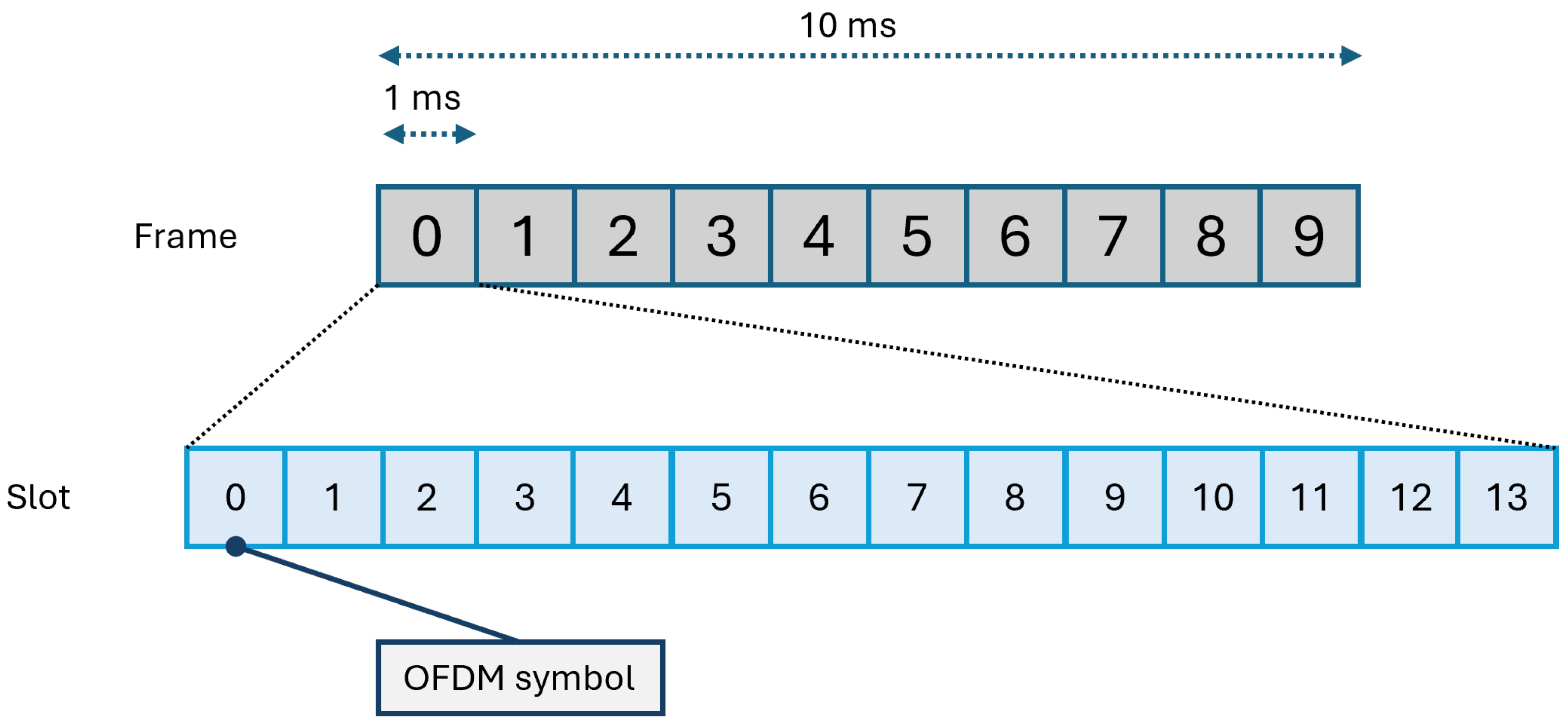
3.1. OFDM Signal and Parameters

In full compliance with the communication standard [34], we opt for an OFDM signal for transmission to and from the UAV. This selection enhances resilience to wireless channel impairments and enables flexible design in both the the time and frequency domains.
The OFDM transmission arrangement follows a hierarchical structure, delineated into frames, sub-frames, and slots, as illustrated in Figure 3. Each frame spans 10 milliseconds and consists of 10 sub-frames, each with a duration of 1 millisecond. Moreover, within each sub-frame, there exists a variable number of slots, with each slot accommodating 14 OFDM symbols. The quantity of slots within a sub-frame is adaptable and is dictated by the numerology, incorporating a potential sub-carrier spacing of Δ f = 2 μ × 15 kHz, where μ = 0 , , 4 signifies the numerology [34,35]. Table 1 reports an example of the Sub-Carrier Spacing (SCS) associated with each numerology and other information as defined by 3GPP. Particular interest is in the last two numerologies introduced by Release 17 of 3GPP, which are intended for use only in the NewRadio millimeter wave bandwidth around 60 GHz.
The OFDM communication signal can be structured into a discrete frequency–time grid denoted as:
Λ FT = ( n Δ f , k T ) n = 0 , , N 1 , k = 0 , , K 1 .
Here, Δ f represents the sub-carrier spacing, T denotes the duration of an OFDM symbol, N stands for the total number of sub-carriers (resulting in an effective system bandwidth of B = N Δ f ), and K is the number of consecutive OFDM symbols.
This study outlines a practical deployment of the transmission system, necessitating various parameters, including bandwidth, sub-carrier spacing, symbol duration, receiver noise figure, and more. These parameters, detailed in Table 2, are drawn from contemporary literature and standards [34,36,37]. The transmitted time domain signal x ( t ) for a single OFDM symbol is constructed by assigning a modulation scheme symbol (e.g., PSK, QAM) to each available sub-carrier. Once M symbols are collected in a vector s ( m ) for m = 0 , , M 1 , each element is multiplied by a complex sinusoid, each with a frequency shift of Δ f compared to the previous one. To generate the final transmitted waveform, a shaping filter g ( t ) is applied to limit each symbol’s time duration. A cyclic prefix is often included in OFDM symbols to guard against multipath interference, equalization aid, mitigate inter-symbol interference, and assist in timing and synchronization at the receiver.
Finally, a single baseband OFDM symbol can be represented as
x ( t ) = m = 0 M 1 s ( m ) e j 2 π m Δ f t g ( t ) .
The pulse-shaping filter is defined as
g ( t ) = { 1 t T CP , T , 0 otherwise ,
where T c p denotes the cyclic prefix interval, and the total symbol duration is T s = T + T CP . The overall bandpass transmitted signal for a single frame composed of N OFDM symbols is
x ¯ ( t ) = e j 2 π f c t n = 0 N 1 x ( t n T s ) ,
where f c represents the carrier frequency, and n is the index of the OFDM symbol within the frame.

3.2. Pulse Compression

The initial step in the processing chain leading to the focused SAR image involves pulse compression of the OFDM signal. This step is fundamental to estimating the time delay of all the echoes sensed at the receiver. While various studies have addressed the challenge of pulse compression for OFDM signals, including works by Rodriguez et al. [38,39], executing this procedure onboard the drone can occur in two ways. The first method involves using the conventional matched filter, performed either in the time domain through convolution or in the frequency domain via multiplication. Alternatively, the inversion technique, known in communication terminology as Zero Forcing (ZF), presents another avenue.
In the first approach, the received signal undergoes multiplication by the complex conjugate of the transmitted signal in the frequency domain
X RC ( f ) = X * ( f ) X RX ( f ) ,
where X ( f ) and X RX ( f ) represent the frequency domain representations of the transmitted and received signals, respectively, and the * symbol is the complex conjugate operator. Subsequently, a simple inverse Fourier Transform of X RC ( f ) yields the range compressed signal. However, one potential limitation of this method lies in the absence of spectrum equalization. If the amplitude of the spectrum varies across the bandwidth post-multiplication, the Impulse Response Function (IRF) may exhibit sidelobes and deviate significantly from an ideal cardinal sine function. This condition is particularly evident when different sub-carriers possess varying associated powers, resulting in an unbalanced power spectrum.
An alternative strategy involves employing a ZF receiver, wherein the received signal is multiplied by the inverse of the transmitted signal
X RC ( f ) = 1 X ( f ) X RX ( f ) .
However, a drawback of this approach lies in the potential for high values in the inverse filter due to samples close to zero. To mitigate this issue, the inverse procedure can be redefined as
X RC ( f ) = 1 X ( f ) + k X RX ( f ) ,
where k accounts for the SNR and channel response, and is defined based on the scenario.

3.3. SAR Image Formation

After pulse compression, we generate a SAR image using the Time Domain Back Projection (TDBP) algorithm, which is well suited for the non-linear trajectories typical of lightweight UAV systems. In TDBP, each pulse (range-compressed OFDM symbol) is interpolated onto a grid representing the area of interest and then re-phased using the platform’s trajectory data. The interpolated and re-phased pulses are then coherently summed to produce the final high-resolution SAR image.
We can mathematically define the TDBP algorithm for a specific pixel of our grid at position x , y as
F ( x , y ) = x RC t = R ( τ : x , y ) c , τ e j 4 π λ R ( τ : x , y ) d τ ,
where F ( x , y ) is the resulting 2D SAR image, c is the speed of light, λ is the wavelength, and R ( τ : x , y ) is the radar-to-pixel distance taken from UAV trajectory estimate at instant τ for the x , y pixel. x RC ( t , τ ) is the range-compressed signal. The time axes that define this signal are referred to in radar terminology as fast-time and slow-time. The first, t, is the time axis of a single received pulse, while the second, τ , is sampled at every pulse.
The main downside of TDBP lies in its computational complexity, which is O ( N 3 ) , assuming a grid of size N × N and a trajectory with N positions used in focusing. We must compute the radar-to-pixel distances, interpolate the range-compressed data, and perform a complex multiplication for each pulse. More efficient algorithms can produce the same image with fewer operations, such as the Fast Factorized Back Projection introduced in [40]. Additionally, the original TDBP algorithm can be easily parallelized and is well suited for GPU acceleration.

3.4. RSSI-Based Localization

The foundation of the active phase of our proposed method is RSSI-based localization. In this approach, we utilize the RSSI to achieve ranging and position estimation of the RF transmitter. RSSI measures the power level received by a receiver, typically expressed in decibels (dB). By collecting RSSI measurements from a UAV-mounted base station, we can estimate the positions of individuals relative to the UAV location.
The methodology involves the UAV continuously scanning the operational area and collecting RSSI measurements. These measurements are timestamped and tagged with the UAV’s current GPS coordinates. Trilateration is the primary technique used to estimate the user equipment’s most likely position. However, trilateration requires distance measurements, not RF power measurements. To convert an RSSI measurement to a range estimate, we use a model first proposed in [41] and also used in [32]. The received power can be expressed as
P RX = P ref n p · 10 log 10 d d ref + n ,
where P ref is the power received at the reference distance d ref , n p is the path loss propagation index, and n is the random shadowing component, modeled as Gaussian zero-mean in dB. This formulation is well suited for RSSI-based localization because this measure is typically a relative power indication, not an absolute one. To achieve accurate localization, we need to empirically calibrate the receiver by sensing the transmitted signal at a known reference distance, allowing us to adjust the measured values to the actual power levels. The path loss propagation index, ideally equal to two in free-space conditions, can vary depending on the propagation environment, reaching values of four or five in urban scenarios.
To convert the RSSI measurement to a distance, we invert the model while accounting for the noisy nature of the measurements. We model a single RSSI measurement ρ i as a non-linear function of the state vector u , representing the position of the RF ground transmitter, and s i , the UAV position at the i-th RSSI observation. This is described by
ρ i = h ( u , s i ) + n i , i = 1 , , N O ,
where N O is the number of RSSI observations, n i is the zero-mean additive Gaussian noise with standard deviation σ i , and
h i ( u , s i ) = P ref n p · 10 log 10 u s i d ref ,
is a non-linear function of the state vectors ( u , s i ) derived from (9) with d = u s i . To determine the most likely position of the ground RF transmitter, we use a Maximum Likelihood (ML) estimator, defined as
u ^ ML = arg max u i = 1 N O 1 2 π ( σ i ) 2 e ρ i h i ( u , s i ) 2 σ i 2 .
This method generates a probability map, where each pixel’s amplitude represents the likelihood of an RF emitter being at that specific location. This information is precious for rescuers, as it can correlate with electromagnetic emissions from the handheld devices of distressed individuals.

4. Numerical Results

To demonstrate the effectiveness of the proposed system, we conducted extensive simulations to evaluate its performance across various challenging scenarios. These simulations were designed to rigorously test the system’s capabilities in environments that closely mimic real-world conditions encountered during search-and-rescue operations. We varied parameters such as the UAV altitude, the depth of the buried targets, snow wetness, and the incidence angle to assess the robustness and accuracy of the localization technique under different circumstances. First, we present the results of the “passive” localization phase, where the drone scans the area to generate SAR images. Following this, we introduce the concept of the “active” phase, where the UAV measures the RSSI to localize the ground user that is actively transmitting. This dual-phase approach highlights the system’s versatility and effectiveness in improving search-and-rescue missions in diverse and challenging environments.

4.1. Passive Phase

The initial phase is termed “passive” because the user on the ground does not actively participate in the localization procedure. To demonstrate the effectiveness of this phase of our proposed localization method, we assess two critical metrics in challenging scenarios: NESZ and channel capacity. Our goal is to provide valuable assistance to rescuers in the operational area while adhering to the configuration of a standard-compliant communication system and enhancing it with sensing capabilities. We conduct simulations for the channel capacity evaluation using the QuaDRiGa channel model [42]. This tool allows researchers to analyze communication systems with real parameters and propagation effects relevant to the scenario [43]. With QuaDRiGa, we can generate channel coefficients based on selected scenarios from preloaded options. The Non-Terrestrial Networks scenario is best suited for the UAV context because it can simulate channels with antennas at an altitude of more than 30 m. All simulations were performed with parameters conforming to industry standards [34,36,44] as listed in Table 2.
The first simulated result shown is the pulse compression comparison, explained previously in Section 3.2. Figure 4a,b report the results utilizing an OFDM waveform with 1024 sub-carriers. In particular, Figure 4a compares the two methods in a scenario where the symbols s ( m ) are randomly selected from a QPSK constellation, ensuring uniform amplitude across all sub-carriers. Notably, even in this scenario where the spectrum is relatively flat, the ZF method effectively suppresses sidelobes, yielding a near-perfect cardinal sine IRF. Figure 4b illustrates examples of pulsed compressed signals with 256-QAM modulated sub-carriers. Here, each of the 1024 sub-carriers exhibits different powers based on the assigned symbol. While the matched filter demonstrates commendable compression, the noise floor remains higher than the ZF approach. Next, we set up a simulation scenario where the UAV provides connectivity to rescuers on the ground. Channel capacity is a good metric for evaluating the quality of the communication link. Shannon’s formula for the information rate [45] can be used, which is expressed as
C = B log 2 ( 1 + S N R )
where C is the theoretical maximum uncoded channel capacity in bits per second, B is the channel’s bandwidth, and S N R is the Signal-to-Noise Ratio expressed as a linear power ratio.
Figure 5 presents the simulation results of a 64-QAM communication link between the flying UAV and ground rescuers. This measurement quantitatively assesses the system’s ability to perform uplink and downlink data transmissions between the UAV and rescuers, facilitating the exchange of information such as SAR images or updated position estimates from the localization procedure. Additionally, we analyze the system’s NESZ in a specific search-and-rescue scenario. NESZ measures the system’s sensitivity to areas with low radar backscatter, representing the equivalent normalized radar cross-section ( σ 0 ) that results in a unitary SNR.
To rigorously test the system, we cap the Equivalent Isotropic Radiated Power (EIRP) at 10 dBm, compared to the standard maximum of 23 dBm. The NESZ derivation considers two main components: symbol duration and Pulse Repetition Frequency (PRF). In the ISAC context, we first need to define the concept of a pulse and its duration. One approach is the symbol-based pulse, where an equivalent radar pulse corresponds to a single OFDM symbol lasting 8 μ s, resulting in a PRF of 125 kHz. This yields an unambiguous range of R amb = c / ( 2 PRF ) = 1200 m. Alternatively, there is the frame-based pulse, where the equivalent radar pulse spans an entire frame consisting of N OFDM symbols. As the pulse length increases by a factor of N, so does the unambiguous range. Considering the duty cycle, the frame-based pulse offers more flexibility in defining on-off periods. However, both approaches yield the same NESZ. A shorter pulse results in less pulse compression gain but allows greater integration gain in azimuth compression. Conversely, with a pulse N times longer, we achieve higher pulse compression gain but fewer pulses to integrate, resulting in lower azimuth compression gain. Nonetheless, the SNR and NESZ remain consistent across both interpretations. Although the unambiguous range and Doppler bandwidth may vary, these factors do not impact the NESZ measure. In Figure 6, we evaluate the NESZ for various incidence angles and nominal heights of the UAV, assuming a target positioned above the snowpack. The antenna pattern is the main influencing factor in this analysis, dictating the shape of the curves. As anticipated, higher altitudes result in lower sensitivity and, consequently, higher NESZ values due to increased power loss over longer propagation distances. Nonetheless, even at high incidence angles, the NESZ values demonstrate the system’s capability to detect targets with low backscatter. Subsequently, we assess the system’s performance in a realistic search-and-rescue scenario where a UAV-based ISAC system could be beneficial. We consider a scenario where one or more victims are trapped under the snow, such as after an avalanche. As demonstrated earlier, with the channel capacity, a base station on the UAV can offer communication services to the search-and-rescue team while simultaneously sensing buried victims under the snow. In Figure 7a, we compute the NESZ for different depths of victims with a fixed drone height of 150 m. To calculate the power loss experienced by the signal traversing dry snow, we utilize the model described in [46]. All other parameters remain consistent with those in Figure 7b. This analysis reveals that even faint targets can be detected with shallow depths or small incident angles. However, as the snow depth exceeds 2 m, either lowering the flying altitude or increasing the transmitted power is necessary to boost the resulting SNR. These simulated results match the one presented in Figure 9.
Another parameter to consider when studying snow is wetness, represented as the percentage of liquid water in a volume of snow. This characteristic is relevant because it affects the scattering mechanism between snow particles and impinging EM waves. Generally, snow wetness is directly proportional to the absorption coefficient, as it elevates the material’s dielectric constant [47]. To visually assess the impact of increasing wetness and altering the altitude of the UAV platform, we conducted simulations varying both parameters. We plot the NESZ values in Figure 8. As wetness approaches 3%, the NESZ reaches the 0 dB limit, posing a challenge for any sensing task. Conversely, the altitude of the UAV has a lesser impact on the system’s sensitivity compared to wetness.
Furthermore, we developed a comprehensive SAR simulator to validate the ISAC system’s ability to accurately image point targets and to qualitatively analyze the system’s IRF. The modulation scheme used for generating the OFDM symbols is a 64-QAM. In our simulated scenarios, we include an ideal point scatterer positioned at an off-nadir angle of 45 degrees. The target has a Radar Cross Section (RCS) of σ = 1 m 2 and is either on the surface of the terrain or buried under varying snow depths, ranging from 1 to 2 m. The UAV is flying at an altitude of 150 m from the air–snow interface.
Figure 9a displays the IRF when the target is on the surface. As expected, the target is well focused, and the IRF exhibits the characteristic bi-dimensional sinc function of a typical SAR imaging system. Figure 9b–d illustrate the IRF for targets buried under 1, 1.5, and 2 m of snow, respectively. In these simulations, we account only for the power loss due to the snow, excluding other factors like refraction or misfocusing effects. It is evident that as the target is buried deeper, both the SNR and the NESZ deteriorate, thereby making target detection progressively more difficult.

4.2. Active Phase

This section presents simulated results of the active phase of the proposed localization method. As explained in Section 3.4, RSSI measures can be leveraged to estimate the most likely position of a ground RF transmitter. The primary drawback of RSSI is its noisy nature. RSSI can be affected by factors such as interference or absorption by obstacles. Consequently, the resulting localization estimates do not achieve the centimeter-level precision possible with radar systems but rather an accuracy in the 5 to 10 m range as noted in [32]. It is important to note that while RSSI-based localization offers a practical solution for our specific scenario, its accuracy can be affected by factors like signal reflection and absorption. In future work, we plan to explore the integration of complementary localization techniques, such as angle-of-arrival or time-of-flight measurements, which could potentially enhance localization accuracy, especially in environments with more complex signal propagation characteristics.
Figure 10 illustrates the likelihood map generated using Equation (12). To create a synthetic version of the RSSI, we use the QuaDriGa channel simulator in conjunction with a UAV track recorded in a real-world flight, represented by the red dotted line. By identifying the coordinates at the maximum of this function, we can estimate the position of the ground transmitter with an error of 2.8 m in this scenario. The green marker and the red diamond represent the estimated and actual positions of the ground transmitter, respectively. Despite this, the information provided can significantly aid rescuers during the target classification phase. Many false targets might appear in a single radar image, potentially slowing search-and-rescue operations. RSSI-based localization helps filter these false targets, thereby enhancing the efficiency and effectiveness of rescue efforts.

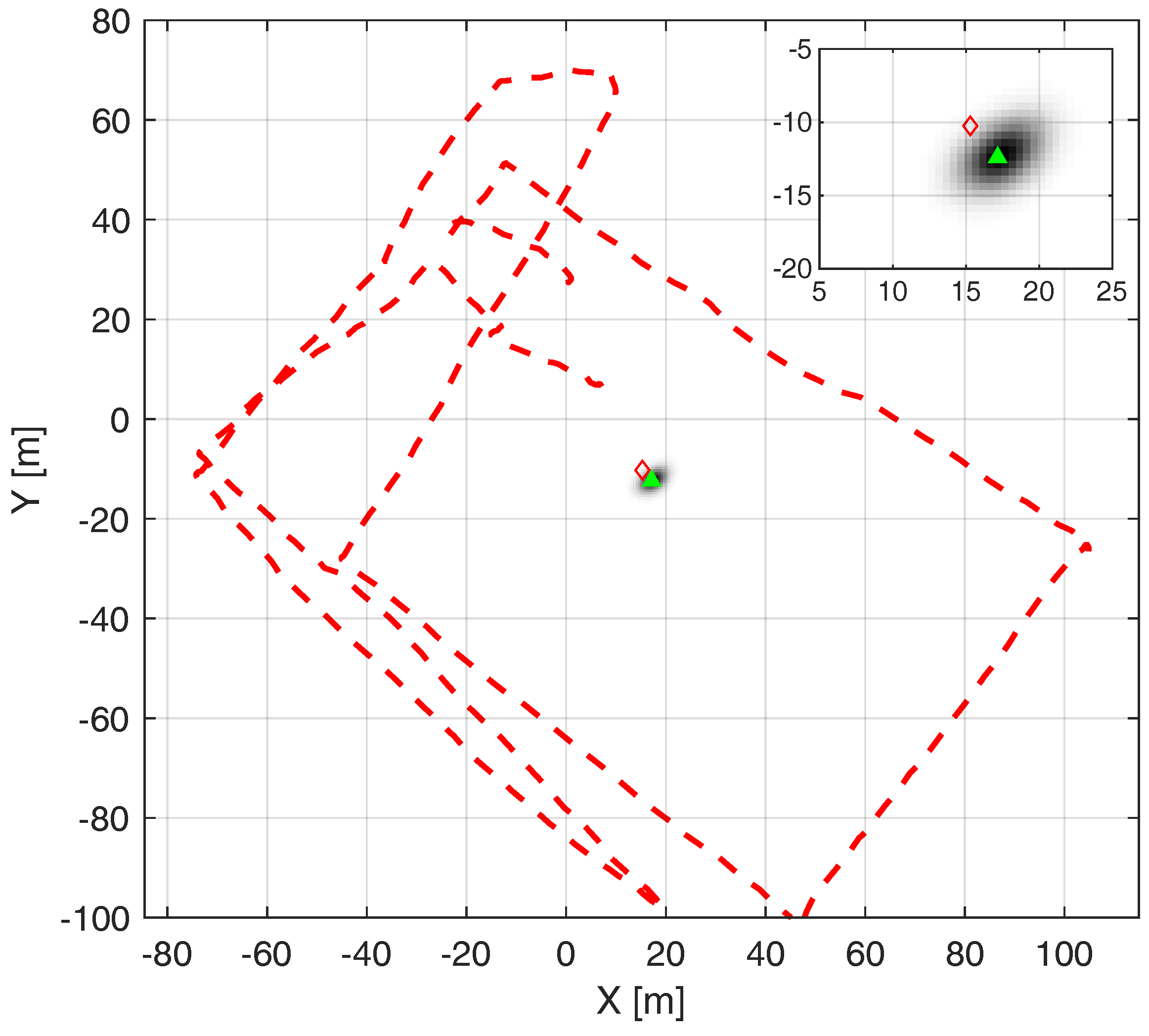
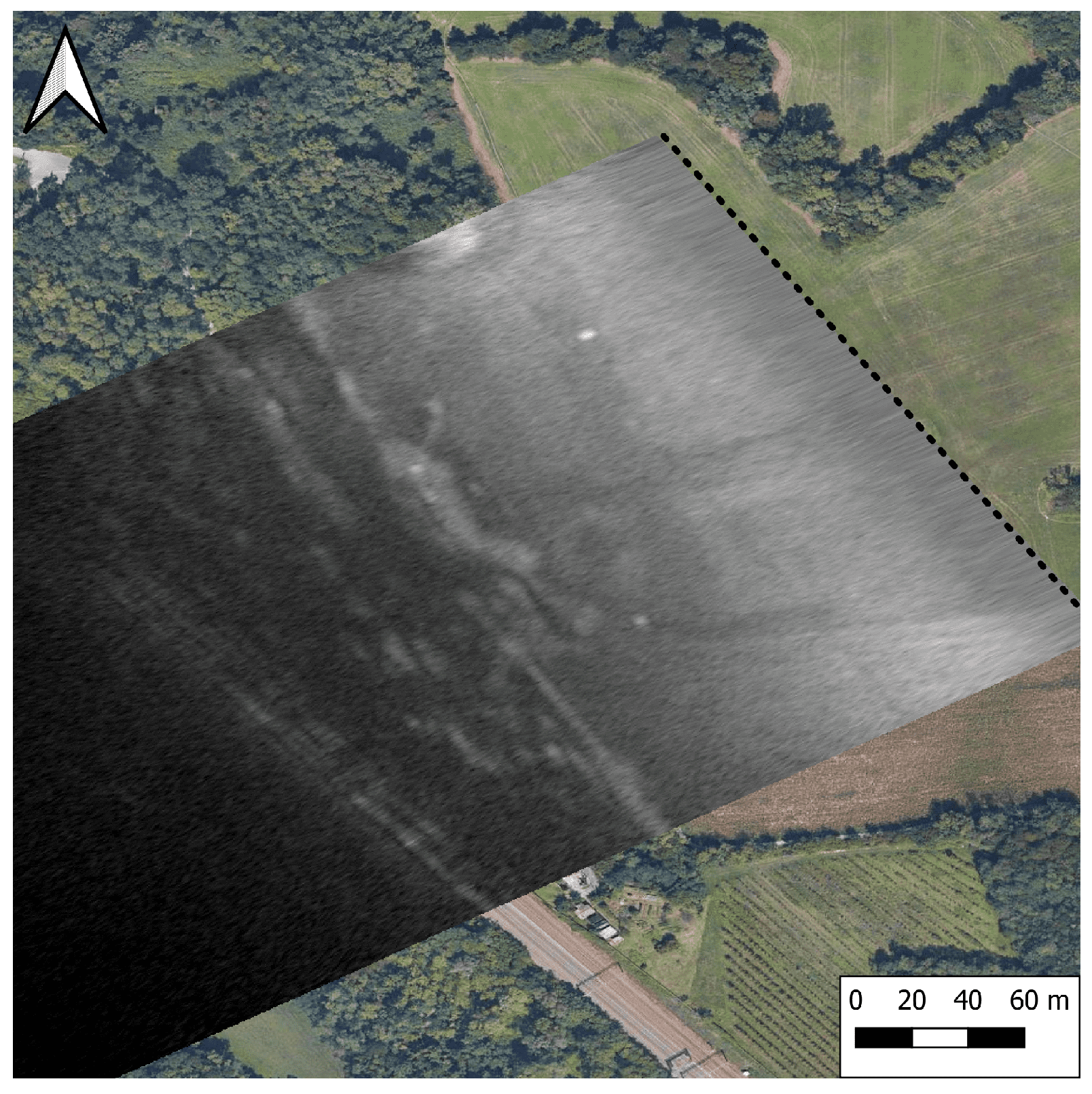
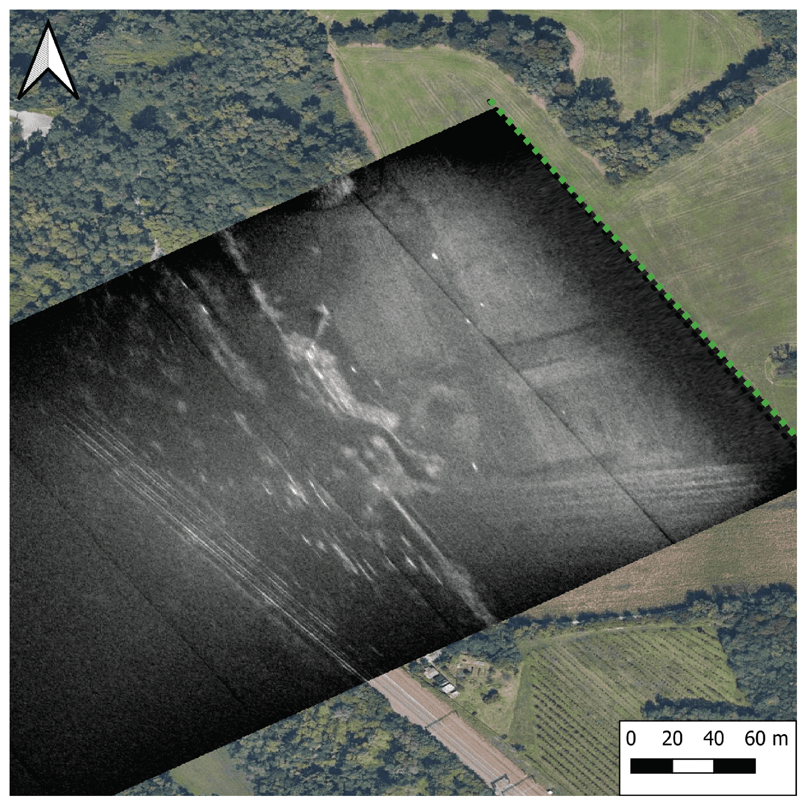
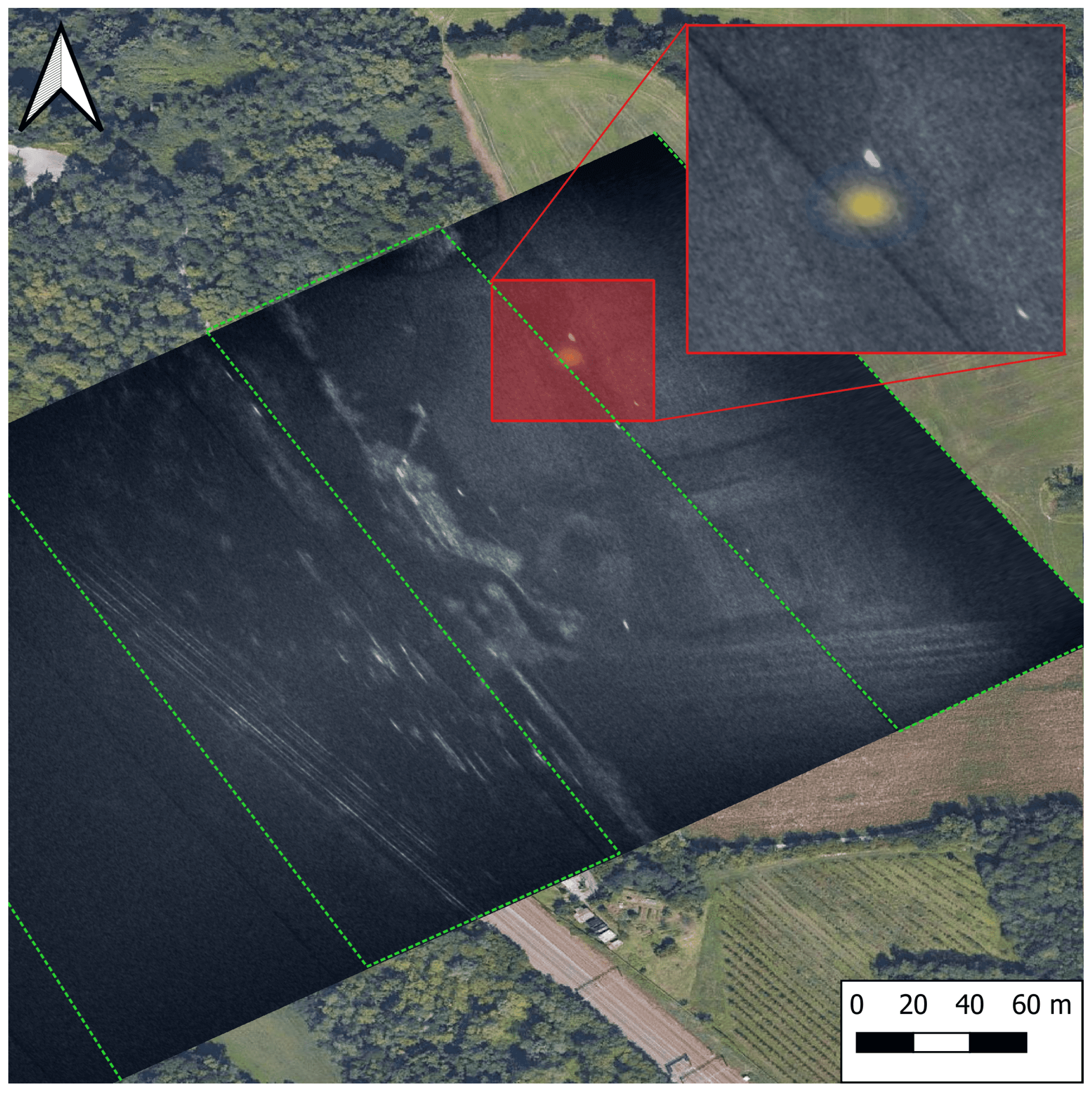
5. Experimental Results

This section presents the results from an experimental campaign, where real data are collected by a radar payload mounted on an ItalDron Potenza 8HSE, a heavy-lifting UAV with a maximum payload capacity of 10 kg. In our configuration, with a 5 kg payload, the UAV achieves a flight time of 30 min. The radar setup is based on an FMCW design, where a Zeus MPSoC generates a triangular CHIRP at 2.5 GHz that is modulated up to 10 GHz by an RF frontend, all developed by Aresys srl. The transmitted waveform is a standard radar waveform, but we can still emulate an OFDM transmission by convolving an OFDM symbol for each range line in the range-compressed data matrix. By this step, we can also adapt the bandwidth of the transmitted signal to one of the OFDM symbols. Then, we can apply a standard MF or ZF filter to simulate the compression of an OFDM symbol, as explained in Section 3.2. Moreover, we have to adjust the PRF of the data to match the one of the communication base stations. Finally, we can focus the image with a standard Time Domain Back Projection (TDBP), resulting in the image shown in Figure 11. The scene represents an airfield in the neighborhood of Milan, as it is easily recognizable by the cross-like runway visible in Figure 12. We position a set of corner reflectors in the field as reported in Figure 13. When focused, these objects generate great reference points because they have an ideal impulse response in azimuth and range. Moving toward the west, the tree line, a house block, and a railway are visible. Comparing Figure 11 and Figure 12, we can appreciate the loss in resolution between the two. The original radar image is produced with a bandwidth of 400 MHz, while the OFDM one has only 40 MHz. These facts reduce the theoretical resolution from 37 cm to 3.7 m. Figure 12 presents a line with low intensity, parallel to the drone trajectory. This artifact is introduced by a notch filter that is made necessary by the interference in the FMCW radar but has no physical meaning. Both images are generated by a multisquint processor and normalized with respect to the maximum intensity of each image.
Furthermore, we aim to incorporate the active localization phase into our findings. However, we cannot integrate the RSSI receiver onto the same UAV platform that generated the radar image. To address this limitation, we utilize the QuaDRiGa channel simulator to simulate the active localization phase, as detailed in Section 4. Our approach involve selecting a corner reflector in the radar image to represent the actual position of ground User Equipment (UE) acting as the victim in danger. We then simulate the RSSI measurements that a UAV, flying a scan pattern over the area of interest, would obtain. Using the ML approach, detailed in Section 4.2, we superimpose the resulting localization data onto the radar image. These combined results are illustrated in Figure 14. Despite an initial localization error, this level of accuracy still allows effective target discrimination in the SAR image. Specifically, the ML map enables us to distinguish between the actual victim and other corner reflectors, which, in our scenario, correspond to clutter.

6. Conclusions

In this paper, we present a novel UAV-based localization and sensing system leveraging ISAC technology. Our approach utilizes an OFDM signal structure to enable radar imaging and communication functions. Through extensive simulations and real-world experimental data, we demonstrate the system’s capability to accurately localize targets and provide high-quality SAR images even under challenging conditions, such as varying UAV altitudes, snow depths, and wetness levels. Our performance evaluation, including metrics like NESZ and channel capacity, confirms the robustness and efficiency of our method. The results showcase the potential of our system to significantly aid search-and-rescue operations by providing real-time, reliable information. While UAVs’ limited range and battery life present challenges, strategies such as optimized power management, relay networks, rapid battery swapping/recharging, hybrid power systems, and task-specific UAV design offer promising avenues to address these limitations and enhance the system’s effectiveness in prolonged missions. Future work will concentrate on developing advanced multistatic radar algorithms through the deployment of UAVs in formation flying configurations, conducting extensive field experiments in diverse snowy conditions to further validate and optimize system performance, and investigating the integration of more sophisticated localization methods such as angle-of-arrival or time-of-flight to enhance accuracy and robustness. Overall, integrating radar sensing with communication capabilities in a single UAV platform offers a powerful tool for enhancing situational awareness and operational effectiveness in critical scenarios.

Author Contributions

Conceptualization, S.M., F.L., M.M. (Marco Manzoni) and S.T.; Data curation, S.M.; Formal analysis, S.M. and M.M. (Marco Manzoni); Funding acquisition, M.M. (Maurizio Magarini) and S.T.; Investigation, S.M. and M.M. (Marco Manzoni); Methodology, F.L. and M.M. (Marco Manzoni); Project administration, M.M. (Maurizio Magarini) and S.T.; Resources, S.M., F.L. and M.M. (Marco Manzoni); Software, S.M. and M.M. (Marco Manzoni); Supervision, M.M. (Maurizio Magarini) and S.T.; Validation, S.M., F.L. and M.M. (Marco Manzoni); Visualization, S.M.; Writing—original draft, S.M.; Writing—review and editing, F.L. and M.M. (Marco Manzoni). All authors have read and agreed to the published version of the manuscript.

Funding

We are glad to acknowledge that the European Union partially supported this work under the Italian National Recovery and Resilience Plan (NRRP) of NextGenerationEU, partnership on “Telecommunications of the Future” (PE00000001-program “RESTART”) CUP: D43C22003080001, Structural Project S 13 ISaCAGE.

Data Availability Statement

No dataset is publicly available.

Acknowledgments

The experimental setup development and the campaigns were carried out in collaboration with Aresys s.r.l. in the context of the JRC activity UAV MULTIDIMENSIONAL SAR IMAGING.

Conflicts of Interest

The authors declare no conflict of interest.

Abbreviations

The following abbreviations are used in this manuscript:
EIRPEquivalent Isotropic Radiated Power
FMCWFrequency Modulated Continuous Wave
IMSIInternational Mobile Subscriber Identity
IRFImpulse Response Function
ISACIntegrated Sensing And Communication
MLMaximum Likelihood
NESZNoise Equivalent Sigma Zero
OFDMOrthogonal Frequency Division Multiplexing
PRFPulse Repetition Frequency
QuaDRiGaQUAsi Deterministic RadIo channel GenerAtor
RCSRadar Cross Section
RSSIReceived Signal Strength Indicator
SARSynthetic Aperture Radar
SDRSoftware Defined Radio
SNRSignal to Noise Ratio
UAVUnmanned Aerial Vehicle
UEUser Equipment
ZFZero Forcing

References

  1. Dong, F.; Liu, F.; Cui, Y.; Lu, S.; Li, Y. Sensing as a Service in 6G Perceptive Mobile Networks: Architecture, Advances, and the Road Ahead. IEEE Netw. 2024, 38, 87–96. [Google Scholar] [CrossRef]
  2. Demirhan, U.; Alkhateeb, A. Integrated sensing and communication for 6G: Ten key machine learning roles. IEEE Commun. Mag. 2023, 61, 113–119. [Google Scholar] [CrossRef]
  3. Blunt, S.D.; Cook, M.R.; Stiles, J. Embedding information into radar emissions via waveform implementation. In Proceedings of the 2010 International Waveform Diversity and Design Conference, Niagara Falls, ON, Canada, 8–13 August 2010; pp. 195–199. [Google Scholar]
  4. Huang, Y.; Hu, S.; Ma, S.; Liu, Z.; Xiao, M. Designing low-PAPR waveform for OFDM-based RadCom systems. IEEE Trans. Wirel. Commun. 2022, 21, 6979–6993. [Google Scholar] [CrossRef]
  5. Pucci, L.; Paolini, E.; Giorgetti, A. System-Level Analysis of Joint Sensing and Communication based on 5G New Radio. IEEE J. Sel. Areas Commun. 2022, 40, 2043–2055. [Google Scholar] [CrossRef]
  6. Liu, Y.; Liao, G.; Chen, Y.; Xu, J.; Yin, Y. Super-Resolution Range and Velocity Estimations With OFDM Integrated Radar and Communications Waveform. IEEE Trans. Veh. Technol. 2020, 69, 11659–11672. [Google Scholar] [CrossRef]
  7. Shi, C.; Wang, F.; Sellathurai, M.; Zhou, J.; Salous, S. Power Minimization-Based Robust OFDM Radar Waveform Design for Radar and Communication Systems in Coexistence. IEEE Trans. Signal Process. 2018, 66, 1316–1330. [Google Scholar] [CrossRef]
  8. Zhang, Y.; Aditya, S.; Clerckx, B. Input Distribution Optimization in OFDM Dual-Function Radar-Communication Systems. arXiv 2023, arXiv:2305.06635. [Google Scholar] [CrossRef]
  9. Keskin, M.F.; Koivunen, V.; Wymeersch, H. Limited Feedforward Waveform Design for OFDM Dual-Functional Radar-Communications. IEEE Trans. Signal Process. 2021, 69, 2955–2970. [Google Scholar] [CrossRef]
  10. Bekkali, N.; Benammar, M.; Bidon, S.; Roque, D. Optimal Power Allocation in Monostatic OFDM Joint Radar Communications Systems. In Proceedings of the 2022 IEEE Radar Conference (RadarConf22), New York City, NY, USA, 21–25 March 2022; pp. 1–6. [Google Scholar] [CrossRef]
  11. Liu, Y.; Liao, G.; Xu, J.; Yang, Z.; Zhang, Y. Adaptive OFDM Integrated Radar and Communications Waveform Design Based on Information Theory. IEEE Commun. Lett. 2017, 21, 2174–2177. [Google Scholar] [CrossRef]
  12. Du, Z.; Zhang, Z.; Yu, W. Information theoretic waveform design for OFDM radar-communication coexistence in Gaussian mixture interference. IET Radar Sonar Navig. 2019, 13, 2063–2070. [Google Scholar] [CrossRef]
  13. Baquero Barneto, C.; Riihonen, T.; Turunen, M.; Anttila, L.; Fleischer, M.; Stadius, K.; Ryynänen, J.; Valkama, M. Full-Duplex OFDM Radar With LTE and 5G NR Waveforms: Challenges, Solutions, and Measurements. IEEE Trans. Microw. Theory Tech. 2019, 67, 4042–4054. [Google Scholar] [CrossRef]
  14. Barneto, C.B.; Liyanaarachchi, S.D.; Riihonen, T.; Heino, M.; Anttila, L.; Valkama, M. Beamforming and Waveform Optimization for OFDM-based Joint Communications and Sensing at mm-Waves. In Proceedings of the 2020 54th Asilomar Conference on Signals, Systems, and Computers, Pacific Grove, CA, USA, 1–5 November 2020; pp. 895–899. [Google Scholar] [CrossRef]
  15. Liu, F.; Zhou, L.; Masouros, C.; Li, A.; Luo, W.; Petropulu, A. Toward dual-functional radar-communication systems: Optimal waveform design. IEEE Trans. Signal Process. 2018, 66, 4264–4279. [Google Scholar] [CrossRef]
  16. Manzoni, M.; Linsalata, F.; Magarini, M.; Tebaldini, S. Integrated Communication and Imaging: Design, Analysis, and Performances of COSMIC Waveforms. arXiv 2024, arXiv:2405.19481. [Google Scholar] [CrossRef]
  17. Meng, K.; Wu, Q.; Xu, J.; Chen, W.; Feng, Z.; Schober, R.; Swindlehurst, A.L. UAV-Enabled Integrated Sensing and Communication: Opportunities and Challenges. IEEE Wirel. Commun. 2024, 31, 97–104. [Google Scholar] [CrossRef]
  18. Petritoli, E.; Leccese, F.; Ciani, L. Reliability assessment of UAV systems. In Proceedings of the 2017 IEEE International Workshop on Metrology for AeroSpace (MetroAeroSpace), Padua, Italy, 21–23 June 2017; pp. 266–270. [Google Scholar] [CrossRef]
  19. Gu, X.; Zhang, G. A survey on UAV-assisted wireless communications: Recent advances and future trends. Comput. Commun. 2023, 208, 44–78. [Google Scholar] [CrossRef]
  20. Trotta, A.; Di Felice, M.; Chowdhury, K.R.; Bononi, L. Fly and recharge: Achieving persistent coverage using small unmanned aerial vehicles (SUAVs). In Proceedings of the 2017 IEEE ICC, Paris, France, 21–25 May 2017; pp. 1–7. [Google Scholar]
  21. Cui, Y.; Liu, F.; Jing, X.; Mu, J. Integrating sensing and communications for ubiquitous IoT: Applications, trends, and challenges. IEEE Netw. 2021, 35, 158–167. [Google Scholar] [CrossRef]
  22. Grathwohl, A.; Stelzig, M.; Kanz, J.; Fenske, P.; Benedikter, A.; Knill, C.; Ullmann, I.; Hajnsek, I.; Moreira, A.; Krieger, G.; et al. Taking a look beneath the surface: Multicopter UAV-based ground-penetrating imaging radars. IEEE Microw. Mag. 2022, 23, 32–46. [Google Scholar] [CrossRef]
  23. RECCO Company. Available online: https://www.recco.com (accessed on 16 April 2024).
  24. Grasegger, K.; Strapazzon, G.; Procter, E.; Brugger, H.; Soteras, I. Avalanche Survival After Rescue With the RECCO Rescue System: A Case Report. Wilderness Environ. Med. 2016, 27, 282–286. [Google Scholar] [CrossRef]
  25. Hohlrieder, M.; Mair, P.; Wuertl, W.; Brugger, H. The Impact of Avalanche Transceivers on Mortality from Avalanche Accidents. High Alt. Med. Biol. 2005, 6, 72–77. [Google Scholar] [CrossRef] [PubMed]
  26. Linsalata, F.; Albanese, A.; Sciancalepore, V.; Roveda, F.; Magarini, M.; Costa-Perez, X. OTFS-superimposed PRACH-aided Localization for UAV Safety Applications. In Proceedings of the 2021 IEEE GLOBECOM, Madrid, Spain, 7–11 December 2021; pp. 1–6. [Google Scholar] [CrossRef]
  27. Albanese, A.; Sciancalepore, V.; Costa-Pérez, X. SARDO: An Automated Search-and-Rescue Drone-Based Solution for Victims Localization. IEEE Trans. Mob. Comput. 2022, 21, 3312–3325. [Google Scholar] [CrossRef]
  28. Song, M.; Huo, Y.; Liang, Z.; Dong, X.; Lu, T. UAV Communication Recovery under Meteorological Conditions. Drones 2023, 7, 423. [Google Scholar] [CrossRef]
  29. Jing, X.; Liu, F.; Masouros, C.; Zeng, Y. ISAC from the Sky: UAV Trajectory Design for Joint Communication and Target Localization. IEEE Trans. Wirel. Commun. 2024. [Google Scholar] [CrossRef]
  30. Tan, D.K.P.; He, J.; Li, Y.; Bayesteh, A.; Chen, Y.; Zhu, P.; Tong, W. Integrated sensing and communication in 6G: Motivations, use cases, requirements, challenges and future directions. In Proceedings of the 2021 1st IEEE International Online Symposium on Joint Communications & Sensing (JC&S), Dresden, Germany, 23–24 February 2021; pp. 1–6. [Google Scholar]
  31. Moro, S.; Linsalata, F.; Manzoni, M.; Magarini, M.; Tebaldini, S. Exploring ISAC Technology for UAV SAR Imaging. arXiv 2024, arXiv:2401.10606. [Google Scholar] [CrossRef]
  32. Moro, S.; Teeda, V.; Scazzoli, D.; Reggiani, L.; Magarini, M. Experimental UAV-Aided RSSI Localization of a Ground RF Emitter in 865 MHz and 2.4 GHz Bands. In Proceedings of the 2022 IEEE 95th Vehicular Technology Conference: (VTC2022-Spring), Helsinki, Finland, 19–22 June 2022; pp. 1–6. [Google Scholar] [CrossRef]
  33. Scazzoli, D.; Moro, S.; Teeda, V.; Upadhyay, P.K.; Magarini, M. Experimental Comparison of UAV-Based RSSI and AoA Localization. IEEE Sens. Lett. 2024, 8, 6000104. [Google Scholar] [CrossRef]
  34. Garcia, M.H.C.; Molina-Galan, A.; Boban, M.; Gozalvez, J.; Coll-Perales, B.; Şahin, T.; Kousaridas, A. A Tutorial on 5G NR V2X Communications. IEEE Commun. Surv. Tutor. 2021, 23, 1972–2026. [Google Scholar] [CrossRef]
  35. 3GPP. NR; Physical channels and modulation (Release 15). Technical Specification (TS) 38.211, 3rd Generation Partnership Project (3GPP). 2020. Version 15.8.0. Available online: https://portal.3gpp.org/desktopmodules/Specifications/SpecificationDetails.aspx?specificationId=3213 (accessed on 13 June 2024).
  36. Kenney, J.B. Dedicated Short-Range Communications (DSRC) Standards in the United States. Proc. IEEE 2011, 99, 1162–1182. [Google Scholar] [CrossRef]
  37. Ahangar, M.N.; Ahmed, Q.Z.; Khan, F.A.; Hafeez, M. A survey of autonomous vehicles: Enabling communication technologies and challenges. Sensors 2021, 21, 706. [Google Scholar] [CrossRef] [PubMed]
  38. Rodriguez, J.T.; Colone, F.; Lombardo, P. Supervised Reciprocal Filter for OFDM Radar Signal Processing. IEEE Trans. Aerosp. Electron. Syst. 2023, 59, 3871–3889. [Google Scholar] [CrossRef]
  39. Rodriguez, J.T.; Colone, F.; Lombardo, P. Experimental evaluation of Supervised Reciprocal Filter Strategies for OFDM-radar signal processing. In Proceedings of the 2023 IEEE RadarConf23, San Antonio, TX, USA, 1–5 May 2023; pp. 1–6. [Google Scholar]
  40. Ulander, L.M.; Hellsten, H.; Stenstrom, G. Synthetic-aperture radar processing using fast factorized back-projection. IEEE Trans. Aerosp. Electron. Syst. 2003, 39, 760–776. [Google Scholar] [CrossRef]
  41. Shue, S.; Johnson, L.E.; Conrad, J.M. Utilization of XBee ZigBee modules and MATLAB for RSSI localization applications. In Proceedings of the SoutheastCon 2017, Charlotte, NC, USA, 30 March–2 April 2017; pp. 1–6. [Google Scholar] [CrossRef]
  42. Jaeckel, S.; Raschkowski, L.; Börner, K.; Thiele, L. QuaDRiGa: A 3-D multi-cell channel model with time evolution for enabling virtual field trials. IEEE Trans. Antennas Propag. 2014, 62, 3242–3256. [Google Scholar] [CrossRef]
  43. Pang, L.; Zhang, J.; Zhang, Y.; Huang, X.; Chen, Y.; Li, J. Investigation and comparison of 5G channel models: From QuaDRiGa, NYUSIM, and MG5G perspectives. Chin. J. Electron. 2022, 31, 1–17. [Google Scholar]
  44. 3GPP TS 38.211. NR. Physical Channels and Modulation. 2018. Available online: https://www.3gpp.org/dynareport?code=38-series.htm (accessed on 13 June 2024).
  45. Shannon, C.E. A mathematical theory of communication. Bell Syst. Tech. J. 1948, 27, 379–423. [Google Scholar] [CrossRef]
  46. Tiuri, M.; Sihvola, A.; Nyfors, E.; Hallikaiken, M. The complex dielectric constant of snow at microwave frequencies. IEEE J. Ocean. Eng. 1984, 9, 377–382. [Google Scholar] [CrossRef]
  47. Shi, J.; Dozier, J. Inferring snow wetness using C-band data from SIR-C’s polarimetric synthetic aperture radar. IEEE Trans. Geosci. Remote Sens. 1995, 33, 905–914. [Google Scholar]
Figure 1. Illustration of the search-and-rescue scenario: A UAV flies over an emergency area, providing connectivity services to rescuers on the ground while simultaneously sensing for victims buried beneath the snow.
Remotesensing 16 03031 g001
Figure 2. Block diagram of the proposed localization approach, with each phase attributed to either the UAV or the User Equipment (UE).
Remotesensing 16 03031 g002
Figure 3. Illustration depicting the structure of a typical OFDM frame, showcasing divisions into sub-frames, slots, and individual OFDM symbols.
Remotesensing 16 03031 g003
Figure 4. Impulse response comparison with sub-carriers modulated with different constellation. (a) QPSK modulated sub-carriers. (b) The 256-QAM modulated sub-carriers.
Remotesensing 16 03031 g004
Figure 5. The channel capacity computed for different snow depths with a nominal flying altitude of the UAV of 150 m. The communication link between the drone and a rescuer above the snowpack is based on a 64-QAM.
Remotesensing 16 03031 g005
Figure 6. NESZ for various incidence angles and nominal heights of the UAV, with a target above the snowpack.
Remotesensing 16 03031 g006
Figure 7. NESZ simulations, varying altitude, and snow depth. The wetness of the snow is 1%. (a) Varying snow depth with UAV flying at 100 m altitude. (b) Varying UAV heights with target buried below 1 m of snow.
Remotesensing 16 03031 g007
Figure 8. Effect of snow wetness and UAV altitude change on NESZ. The extinction ratio in the snow can be found in [46].
Remotesensing 16 03031 g008
Figure 9. ISAC system focusing SAR images for an ideal point scatterer placed at different snow depths and a nominal UAV flying altitude of 150 m from the air–snow interface.
Remotesensing 16 03031 g009
Figure 10. Likelihood map generated with the active localization phase. The red dotted line represents the UAV track, with the green marker and the red diamond representing the estimated and real transmitter location, respectively. The estimation error is 2.7 m in this simulated scenario. A zoomed-in perspective at the transmitter location is reported in the top right corner of the figure.
Remotesensing 16 03031 g010
Figure 11. SAR image generated by back-projecting the range-compressed OFDM signal. The black dotted line represents the trajectory of the drone.
Remotesensing 16 03031 g011
Figure 12. SAR image generated with the original FMCW radar setup with full bandwidth. The green dotted line represents the trajectory of the drone.
Remotesensing 16 03031 g012
Figure 13. Optical satellite image of the scene, with superimposed the UAV trajectory in black dotted line and the corner reflectors with the red triangles.
Remotesensing 16 03031 g013
Figure 14. Result of the two-phase localization method: in grayscale, the SAR image is represented, in yellow, the ML map generated with the RSSI-based approach, and the green-dotted line is the UAV scan trajectory.
Remotesensing 16 03031 g014
Table 1. The 3GPP supported numerology.
μ SCS [KHz]N Slot per FrameSlot Duration [ μ s]Usage3GPP Release
015101000Data, SyncRel. 15
13020500Data, SyncRel. 15
26040250DataRel. 15
312080125Data, SyncRel. 15
424016062.5SyncRel. 15
548032031.25Data, SyncRel. 17
696064015.625Data, SyncRel. 17
Table 2. DSRC communication standard parameters.
ParameterValue
f c 5.9 GHz
Maximum bandwidth B40 MHz
Numerology μ 3
Sub-carrier spacing Δ f 120 KHz
Data symbol duration T8.33 μ s
Noise Figure7 dB
EIRP23 dBm
G tmax 10 dB
Disclaimer/Publisher’s Note: The statements, opinions and data contained in all publications are solely those of the individual author(s) and contributor(s) and not of MDPI and/or the editor(s). MDPI and/or the editor(s) disclaim responsibility for any injury to people or property resulting from any ideas, methods, instructions or products referred to in the content.

