1. Introduction
Radar is now facing a severe problem with spectrum congestion, and numerous academics have suggested sharing the wireless communication spectrum with radar [
1,
2,
3,
4]. There is a highly impending need for spectrum sharing across radar and communication due to the significant rise in the number of connected devices [
5,
6,
7,
8,
9,
10]. Therefore, both business and academics have given integrated sensing and communication (ISAC) a lot of attention. As a single platform with two functionalities, ISAC enables sensing and communication to operate simultaneously over identical wide frequency bands [
11,
12,
13,
14,
15], realizing integration and miniaturization while also meeting the demands of contemporary societal development.
Due to these significant advantages, various strategies are proposed to achieve the ISAC, involving waveform design [
16,
17,
18,
19,
20,
21], joint transmit beamforming design [
22,
23,
24,
25,
26,
27,
28], etc. We focus on the joint transmit beamforming design in this paper, where spatial multiplexing of radar and communications is achieved by shipping multiple transmit beams toward targets and communication users. The authors in [
22] studied the beamforming design problems for both separated and shared antenna deployments in a joint RadCom system. A joint beamforming design scheme was studied in [
24], focusing on optimizing sensing performance while satisfying the requirements of communication to obtain the overall beamforming matrix. Recent studies have considered ISAC based on various multiple access techniques [
25,
29] to further enhance spectrum efficiency for both sensing and communication.
The authors in [
25] investigated transmit beamforming for the ISAC based on nonorthogonal multiple access (NOMA) to optimize the weighted sum rate (WSR) of communication users and the radar beam patterns. They suggested a double-layer penalty-based approach to address their optimization problem. Different from the multiaccess method mentioned earlier, authors in [
29] proposed a method for information embedding based on the concept of space-division multiple access (SDMA) and waveform diversity. Compared with using nonorthogonal or space-division methods, the interference in ISAC can be effectively managed by employing more powerful multiple access techniques. For rate-splitting multiple access (RSMA), part of the interference is decoded and the remainder is treated as noise, different from the two extreme interference management strategies, SDMA and NOMA. This is because of the fact that NOMA fully decodes interference, whereas SDMA entirely treats interference as noise [
30,
31,
32,
33,
34,
35,
36,
37,
38]. The system’s WSR and Energy Efficiency (EE) performance are on par with or better than that of SDMA, NOMA, and multiuser linear precoding (MU-LP) [
39,
40,
41,
42,
43]. Research on rate-splitting (RS)-based ISAC systems is meaningful due to its ability to dynamically manage interference [
44,
45].
In this paper, a joint transmit beamforming for the ISAC system is investigated from radar-centric and trade-off perspectives to ensure sensing performance through beam pattern approximation. Similar to [
24], a weighted sum of communication symbols and radar waveforms is used as our transmit signal. Unlike [
24], our research motivation is not solely to maximize sensing performance. To better ensure communication performance, we have also proposed a weighted optimization algorithm that allows for a flexible trade-off between sensing and communication performance by adjusting the relevant parameters. Due to the extreme handling of interference by NOMA and SDMA, their application in ISAC (i.e., NOMA-based ISAC in [
25] and SDMA-ISAC in [
29]) is less advantageous compared with RSMA. We use RS as a multiple access platform for multiuser communication, providing advanced interference management strategies. Unlike [
45], we consider a dual-function waveform, which is the weighted sum of communication symbols and radar waveforms, transmitted by a shared uniform linear array to achieve both communication and sensing functions simultaneously. From a practical perspective, we also consider the interference of radar signals on communication. Although the common stream generated by splitting can increase the system’s degree of freedom (DoF), it still cannot sufficiently compensate for the impact of interference on private message decoding and sensing performance, as the transmit power of the common stream is limited by the user with the worst ability to decode the common part. The authors in [
46] proposed a method to maximize the sum rate of downlink users by controlling the transmit power of a common stream. Building on this, we further propose a beamforming design scheme for ISAC based on partial rate-splitting (P-RS) to address the issue of limited common energy, aiming at enhancing the effective sensing power.
The transmitter in this study maximizes the DoF of multiple-input–multiple-output (MIMO) radar waveforms by using individual communication and radar waveforms. For clarity, the key contributions made by this work are summarized as follows:
We propose a joint beamforming design scheme from a radar-centric viewpoint using beam pattern approximation and achieve optimal beamforming by solving a nonconvex optimization problem.
We further propose a beamforming design scheme from a trade-off viewpoint to ensure communication performance and achieve flexible optimization of sensing and communication performances with a regularization parameter.
We propose a P-RS-based beamforming design scheme aimed at maximizing the effective sensing power of MIMO radar while satisfying the minimum requirement of multiuser communication. Numerical results are provided to assess the effectiveness of all proposed schemes.
The remainder of this work is organized as follows.
Section 2 describes the system model and illustrates the performance metrics of sensing and communication.
Section 3 proposes beamforming design schemes from radar-centric and trade-off viewpoints and proposes a P-RS-based ISAC scheme.
Section 4 provides simulation results,
Section 5 points out our future work, and
Section 6 concludes the paper.
Notations: Vectors and matrices are denoted by bold-face, lower-case, and uppercase letters, respectively (i.e., and represent matrix and vector, respectively). , , and tr refer to Hermitian transpose, transpose, and the trace of the argument, respectively. The diagonal entry vector of a matrix is denoted by diag. We use for the stochastic expectation and subscripts for the columns of a matrix. The operation 0 denotes that is a positive semidefinite matrix. To facilitate understanding of the abbreviations used in this paper, we have compiled them into a reference table and placed it at the end of the article for convenience (see Abbreviations section).
3. Proposed Beamforming Design Schemes
The purpose of this section is to jointly design communication beamforming
and radar beamforming
. We first propose a beamforming scheme from the radar-centric viewpoint using beam pattern approximation and achieve optimal beamforming by solving a nonconvex optimization problem in
Section 3.1. In
Section 3.2, we propose a trade-off scheme to ensure communication sum rate and achieve flexible optimization of sensing and communication performances using a regularization parameter. In
Section 3.3, we propose a P-RS-aided beamforming design scheme aimed at maximizing the effective sensing power of MIMO radar while satisfying the minimum requirement of multiuser communication.
3.1. Radar-Centric Beamforming
In this subsection, we propose a radar-centric beamforming scheme to achieve sensing efficiency through beam pattern approximation, while requiring fairness SINR to be higher than a given threshold to guarantee a minimal level of communication quality. Here, we take
, which is the overall precoding matrix. For ISAC, the covariance matrix
is defined as
Substituting (
1) into (
12), we have
We use
to represent the
column of the matrix
, and
. Therefore, (
13) can be rewritten as
Let
, we have
To guarantee the minimum performance requirements of communication, the rate of decoding the common message at user-
k should be greater than or equal to 0, and the rate of decoding the private message at user-
k should be greater than or equal to a given threshold
, which is expressed as follows
In this work, we take
and require it to be higher than
, which is the SINR value corresponding to the threshold
. Consequently, the optimization problem can be formulated as follows:
In problem (
17), the first column of the matrix
denotes the precoder
for
, and the next
K columns of the matrix
denote precoders of
K private streams. Therefore, the individual matrices
have no effect on the sum rate of the users, and then we can remove it from the matrix
, i.e.,
. Therefore, the problem (
17) becomes
where
is the set of optimization variables,
indicates that the rank of the matrix
is 1. The problem (
18) is nonconvex due to the rank-one constraint. To solve problem (
18), we can obtain the following relaxation by omitting these constraints.
Here, we use the semidefinite relaxation (SDR) algorithm [
51] to solve the nonconvex problem (
18). According to (
3), (
4) and (
14) we have
It is not difficult to find that the optimization problem which substitutes (
19) into (
18) is still nonconvex. The problem can be relaxed as
Since
, …,
are exactly rank-one matrices, the relaxation employed in SDR is tight. Consequently, the solution to the nonconvex problem (
20) also serves as a solution to problem (
18). Derivation can be found at the bottom of this subsection.
The solution
,
, …,
can be obtained by solving problem (
20). A rank-one optimal solution
,
, …,
and the corresponding optimal precoding matrix
are obtained via
The remaining part of the matrix
(i.e.,
) is the precoder
for radar signal, and it can be obtained by using the Cholesky decomposition
Therefore, the overall precoding matrix
. The computational procedure is summarized in Algorithm 1.
| Algorithm 1 Beamforming Design via SDR. |
Input: Instantaneous channel , transmit power , SINR threshold ; Output: Precoder matrix ; 1: Compute the optimal solution by solving problem ( 20); 2: Compute using ( 21) and ( 22); 3: Compute using ( 23); 4: Output the precoder |
Proof. Denote
,
, …,
as an arbitrary global optimal solution to (
20). Now, we construct
,
, …,
from
,
, …,
as
Obviously,
,
, …,
are rank-one and positive semidefinite. We need to prove that
,
, …,
is a global optimum to (
20). From (
24), we have
for any
, it holds that
Then, we can obtain that
on the basis of the Cauchy–Schwarz inequality. Consequently, for any
, there is
. It means that
, and we have
Since
, this means that constraints
, and
in problem (
20) hold for
,
, …,
. The derivation verifies that
,
, …,
is a set of solutions to (
20), and the proof is completed. □
3.2. Beamforming Design for Trade-Off
It should be pointed out that problem in (
17) is focused on the maximization of sensing performance, while it may cause downlink communication performance loss. In this subsection, we consider another beamforming design scheme to achieve a flexible trade-off between sensing and communication performance and propose an iterative method based on weighted minimum mean square error (WMMSE) and SDR to solve the resulting nonconvex optimization problem.
In [
25], the objective function of optimization problem contains two parts, WSR of communication users and radar beam patterns. We use MSE of the beam patterns and WSR as the performance metrics for MIMO radar and multiuser communication, respectively. Similarly, we introduce a regularization parameter
to flexibly control the performance trade-off between communication and radar. Consequently, the beamforming design scheme for trade-off can be formulated as an optimization problem as follows:
Each element of
denotes the portion of
for the corresponding user. o ensure the quality of service (QoS), constraints are imposed on
for decoding the private part and on
for the common part. Due to the presence of quadratic equality constraints in the problem (
28), it exhibits non-convexity.
In the communication part, the existing literature [
37,
38,
39,
40] indicates that user-
k first decodes the estimated common stream
using an equalizer
and remove it from received signal, then we can decode the estimated private stream
using an equalizer
from the remaining message, i.e.,
and
. When decoding
and
at user-
k, the MSEs can be calculated as
By solving
and
, we can obtain the minimized MSE equalizers
and
as follows:
Substituting (
30) into (
29), we have
At user-
k, the SINRs of decoding
and
can be transformed as
,
, then its rates are
The weighted MSEs for decoding
and
are
where
and
are the positive weights for common and private rates of user-
k. We can obtain relationships as follows:
where optimal values are
,
,
,
. By satisfying the first-order optimality conditions, these optimal values are obtained. Subsequently, the problem (
28) can be rewritten as
where
,
and
are the equalizers and weights.
Similarly, for that reason, the individual matrices
have no effect on the sum rate of the users, and we can remove it from the matrix
. Therefore, the problem (
35) is relaxed as follows:
since
, …,
are exactly rank-one, the relaxation by using SDR is tight. The derivation is similar to
Section 3.1.
Briefly, our proposed iterative algorithm based on WMMSE-SDR mainly involves two procedures:
(1) Given the beamforming matrix , the optimal and are obtained by WMMSE;
(2) Given and , the suboptimal , …, , are obtained by SDR.
We can obtain the optimal solution
,
, …,
by solving the problem (
36), then we can compute a rank-one optimal solution
,
, …,
and the corresponding optimal precoding matrix
via (
21) and (
22).
The remaining part of the matrix
(i.e.,
) is the precoder
for radar signal, and we can obtain it by (
23). Therefore, the overall precoding matrix
. We summarize the method to obtain the matrix
as Algorithm 2.
The complexities of Algorithms 1 and 2 are discussed in this paragraph. These two algorithms are completed based on SDR, and we analyze the complexities from the term of SDR by
[
52]. Given a solution accuracy, the number of restrictions
m and the problem size
n have polynomial effects on its difficulty. The number of constraints is the same for the optimization problems (
20) and (
36), while the number of variables of problem (
20) is
and that of problem (
36) is
. Then, the complexity of Algorithm 1 and Algorithm 2 is dominated by the number of variables of problems (
20) and (
36), respectively. Therefore, the complexities of Algorithm 1 is
and the complexity of Algorithm 2 is
. Obviously, the complexity of Algorithm 1 is relatively low.
| Algorithm 2 Iterative Beamforming Algorithm. |
Input: Instantaneous channel ; Transmit power ; Precoder , ; ; while do 1: Compute the optimal solution and by WMMSE; 2: Compute the , , , by solving problem ( 36) with updated and ; 3: Update via ( 21) and ( 22); 4: Update using and ; 5: ; end while Output: The overall precoder ;
|
3.3. P-RS-Based Beamforming
We note that the achievable rate of decoding should not exceed the rate of each user decoding , i.e., , to ensure that a common stream can be decoded by every downlink user. Therefore, the achievable rate of the common stream is limited by the user with the weakest ability to decode the common part among all users making it unable to fully utilize the common stream to reduce the impact of multiuser nonorthogonality on the private streams and sensing performance. To address this issue, we propose a P-RS-based beamforming algorithm to improve the performance of the ISAC system. In our proposed scheme, not all messages are split at the transmitter. Instead, the message of the user with the worst ability to decode the common part will be transmitted directly after being precoded.
The factors that affect a user’s ability to decode the common part may not be unique, among which the most straightforward factor is the channel state. It is hypothesized that the base station determines whether the user’s message is split at the transmitter based on its corresponding channel quality. For instance, the message of a user with poor channel quality is not split but instead precoded as a private stream before transmission. Based on this, we provide an example to verify the effectiveness of our proposed algorithm in enhancing sensing performance for further in-depth research in future work.
All users are divided into two sets, namely set
and set
, by the base station based on their channel status information. Set
comprises users whose messages are split at the transmitter, while set
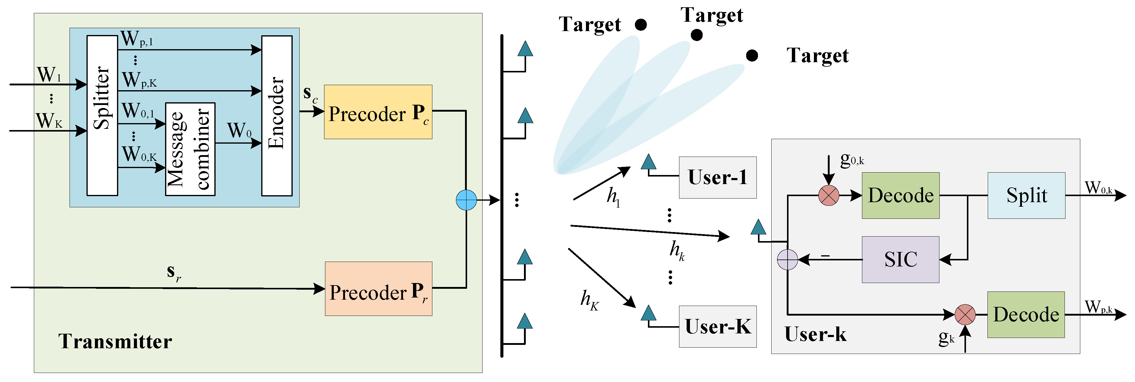
comprises users whose messages are not split due to poor channels. As shown in
Figure 2a, the messages of the users in set
are still split into two parts at the transmitter: a common part and a private part. Meanwhile, the messages of the users in set
are directly encoded as private messages. It is hypothesized that there are
users assigned to set
and
users assigned to set
. It should be noted that
and
, where
K is the total number of downlink users. Particularly, RS is a special case of P-RS when
. At the user in set
, the common message is decoded first, and then the private message is decoded after the common message is eliminated using SIC from the received signal. In contrast, users in set
no longer decode the common message. In other words, the part within the dashed box in
Figure 2b does not work for users in set
, and the corresponding private message is decoded directly. At the user in set
, the interference for decoding its required private message includes not only the private messages of other users but also the interference caused by the common message.
Therefore, the SINRs for user-
a (
), decoding the common message and the private message can be given as
The SINR for user-
b (
) decoding the private message can be given as:
The achievable rates for decoding the common message and private message at user-
a, and the private message at user-
b are, respectively, given as
Then the sum rate of downlink users is
where
is the part of the
corresponding to user-
a. In this subsection, we use the effective sensing power [
25] as the performance metric for MIMO radar. To this end, the proposed P-RS-based transmit beamforming design scheme can be formulated as an optimization problem as follows:
where
,
. Constraint
ensures that the common message can be decoded by every user in set
,
denotes the minimum required sum rate of downlink users. Problem (
44) cannot be solved directly due to its nonconvexity. However, it can be solved through a series of transformations and the use of SDR. The detailed process can be found in
Appendix A. The optimal covariance matrix
can be obtained by solving the problem (
A13) using the SDR method, and then beamformer
can be obtained according to (
21)–(
23).
4. Numerical Results
In this section, we provide simulation results to demonstrate the effectiveness and feasibility of the algorithms proposed in this work. We analyze the radar beam pattern of the proposed schemes compared with the existing scheme of [
45] (i.e., WMMSE-MM), NOMA-ISAC [
25], and SDMA-ISAC, achieved by allocating no power to the common stream) in
Section 4.1.
Section 4.2 analyzes the achievable sum rate of the proposed schemes. Meanwhile, we compare the feasibility of Algorithms 1 and 2. Finally, we validate the effectiveness of the proposed P-RS-based beamforming design scheme in
Section 4.3.
In this ISAC system, we use a uniform linear array with half-wavelength spacing between adjacent antenna elements. It should be noted that the radar beam pattern is calculated by
. In this section, we first demonstrate the superiority of RSMA for ISAC, and then we analyze the numerical results achieved by the beamforming design methods proposed in our paper. The performance difference for the proposed submodel algorithm arises from the varying focus in the dual function. Specifically, the SDR beamformer is concentrated on maximizing sensing performance while meeting the minimum requirements for multiuser communication. In contrast, the WMMSE-SDR achieves a flexible trade-off between communication and sensing performance under the total transmit power constraint. Additionally, enhancing the contribution of the achievable common rate to communication and sensing performance in ISAC is achieved through improvements in multiple access schemes, such as P-RS. We set
,
dB,
dB throughout simulations. Here, we consider three targets, and the locations of the three beams are set at
. The channel vector
follows i.i.d. complex Gaussian distribution. In the following simulation, ‘Rad Only’ is the beam pattern obtained from (
11), We use ‘Radar-centric’ and ‘Trade-off’ to denote the beam patterns obtained for radar-centric beamforming and trade-off beamforming proposed in
Section 3.1 and
Section 3.2, respectively.
4.1. Transmit Beam Pattern Comparison
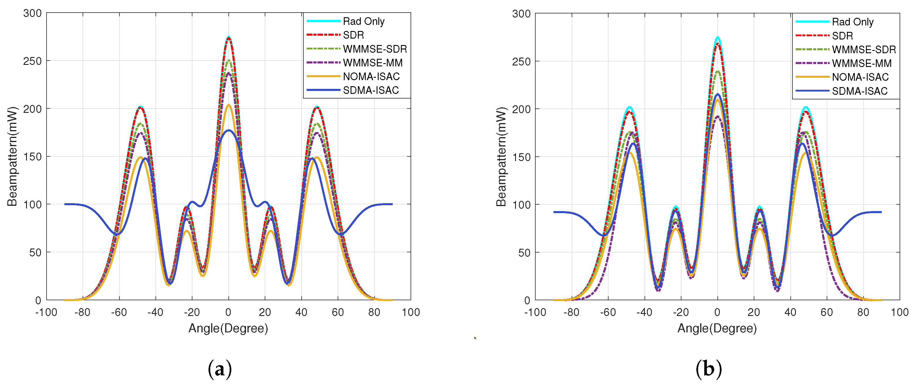
To assess the effectiveness of the algorithms on sensing, we demonstrate the beam pattern obtained by the various schemes with different numbers of communication users, as shown in
Figure 3. We set the weighting factor
and compare the beam patterns obtained by different schemes with
and
.
In
Figure 3a, it can be clearly seen that SDR is fully approaching the ideal beam pattern and has a nearly 2.17 dB gain over SDMA-based ISAC. This superiority is attributed to the flexibility of RSMA in managing interference compared with NOMA and SDMA. Comparing
Figure 3a,b it is evident that the ISAC based on SDMA provides a poor beam pattern when
compared with
due to its lower spatial gain, indicating that SDMA achieves higher spatial gain with more users. Furthermore, the algorithms proposed in this paper outperform the WMMSE-MM algorithm attributed to the transmit signal for our system being a weighted sum of communication symbols and radar waveforms, which are transmitted by a shared uniform linear array to achieve both communication and sensing functions simultaneously to provides MIMO radar waveforms with more DoF. Moreover, the WMMSE-SDR method proposed in our paper can achieve a flexible trade-off between communication and sensing performance by adjusting the parameter
. Meanwhile, it can be observed that the SDR method provides a better beam pattern than WMMSE-SDR. In other words, to further ensure communication performance, WMMSE improves the sum rate of communication at the expense of approximately 0.5 dB of directional gain. A detailed analysis of the communication performance can be found in
Section 4.2.
Similarly, it is not difficult to observe that the power of the main beams towards , , and , steered by the SDR beamformer, exceeds that of the main beams steered by the WMMSE-SDR beamformer. This difference arises because the focuses of these two beamforming design methods are distinct. The SDR beamformer is optimized for radar performance with minimum communication quality constraints, while the WMMSE-SDR beamformer aims to achieve a performance trade-off between communication and radar. This explains why the beam pattern obtained for the SDR beamformer is closest to the Radar only.
Figure 4 is the comparison of detection probability for the design scheme proposed in this paper. The radar detection probability can be calculated by
, where
is the noncentral chi-square cumulative distribution function with two degrees of freedom,
denotes the false alarm probability of the radar detection, the noncentrality parameter
is given by
[
53]. As can be seen, the detection performance of the radar-centric scheme outperforms that of the trade-off scheme due to
being a monotonically increasing function for
, and the radar-centric method can provide better beam pattern gains.
4.2. Achievable Sum Rate Comparison
We first show the achievable weighted sum rate obtained by different schemes in
Figure 5 and
Figure 6, then compare the MSE of radar beam pattern generated by different schemes in
Figure 7. The MSE of the radar beam pattern can be expressed as follows:
We discuss the variation in communication performance with SINR threshold
as illustrated in
Figure 5. We note that the WMMSE-SDR beamforming method produces higher WSR compared with the SDR beamforming method. Meanwhile, it is not difficult to find that the almost same WSR results are obtained by different beamforming methods with the same number of users when the
is high enough.
The relationship between the achievable WSR and MSE is demonstrated in
Figure 6, and it reflects the trade-offs of beamforming design schemes with different numbers of transmit antennas. It is not difficult to observe that more antennas encourage a better trade-off between the WSR and MSE. Moreover, the trade-off design method proposed in this paper outperforms the WMMSE-MM beamformer owing to the transmitter in this paper making MIMO radar achieve larger DoF by using individual communication and radar waveforms. In order to analyze the performance of the ISAC system more comprehensively, the influences of
on the achievable WSR of users and the MSE of radar beam patterns are explored next. The trade-off between the MSE of radar beam patterns and the SINR threshold
for SDR and WMMSE-SDR beamforming is depicted in
Figure 7.
We can observe that the MSE of the SDR algorithm is higher than that of the WMMSE-SDR algorithm, whether the number of users is or . However, the gap between these two curves becomes closer as increases. From the MSE expression, it is evident that the MSE value is associated with . In other words, the MSE value is determined by the optimization variable . In the SDR beamforming method, the objective function of the optimization problem is the radar loss function, which is independent of the number of users.
The quantity related to the number of users is the SINR for the given thresholds in the constraints of the optimization problem. However, in the WMMSE-SDR beamforming method, apart from the SINR constraints, the sum rate component of the objective function is significantly influenced by the number of users. Therefore, the impact of the number of users on MSE in the SDR method is not as pronounced as the impact of MSE in the WMMSE-SDR method.
The proposed joint beamforming design problems (
20) and (
36) are not always feasible. The relationship between the number of users and the feasible probability is demonstrated in
Figure 8. Here, we compare the feasibility of SDR and WMMSE-SDR for
dB and
dB, respectively, as illustrated in
Figure 8a,b. It is noted that the feasible probability for SDR and WMMSE-SDR are almost the same, and both of them decrease as the number of users increases for the reason that a greater user base results in a decrease in the DoFs. The feasible probability decreases when
is increased from 10 dB to 20 dB. Since
is limited, the achievable SINR to users is limited. Therefore, the feasible probability of the two problems will decrease when
increases.
4.3. The Effectiveness of the P-RS-Based Beamforming Design Scheme
In
Section 4.1 and
Section 4.2, we compared the effectiveness of various multiple access methods in ISAC applications and concluded that RSMA is a powerful multiple access and interference management strategy suitable for ISAC. Next, we explore the effectiveness of the proposed P-RS-based beamforming design scheme by comparing it with the transmit beam patterns of ISAC systems based on RS. We use ‘RS’ and ‘P-RS’ to denote the transmit beam patterns obtained by the RS-based and P-RS-based beamforming design schemes, respectively.
We conducted simulations for scenarios with 2 and 8 users, respectively. In the case of , it is hypothesized that one user is in set and another is in set , i.e., , , while in the case of , it is assumed that five users with good channels are in set and three users with poorest channels are in set , i.e., , .
As illustrated in
Figure 9, the transmit beam patterns in the target directions gradually deteriorate as the number of users increases. However, it is evident that ISAC based on P-RS can maintain better performance compared with ISAC based on RS. This is attributed to P-RS no longer splitting the messages of users with a bad ability to decode the common stream, effectively removing the constraint imposed by these users on the common rate.


