Abstract
This paper investigates null control within the transmit–receive beampattern of Frequency Diverse Array-Multiple-Input and Multiple-Output (FDA-MIMO) systems, presenting a novel phase-only optimization approach for achieving null control in FDA-MIMO. We employ an alternating multiplier framework, which transforms the intricate and inherent constant modulus constraint and numerous amplitude constraints in optimization into more manageable projection problems. By employing a phase-only optimization strategy, the intricate hardware and computational burdens associated with null control in FDA-MIMO are effectively alleviated. The simulation results indicate that the algorithm proposed in this paper exhibits excellent null control ability while precisely maintaining constant modulus constraints, and it possesses an extremely high computational efficiency.
1. Introduction
Null control is a crucial technique in beamforming [1], widely employed in the field of radar systems. By controlling nulls in array antenna systems, it is possible to effectively suppress interference signals, thereby enhancing the performance of signal reception or transmission. Currently, null control has garnered extensive attention and research in practical applications, achieving significant advancements. For instance, in radar systems, null control can be utilized to suppress spurious targets or interference sources in echoes, thereby improving target detection and tracking performance [2].
Indeed, the problem of synthesizing beampatterns with widened nulls has been extensively investigated [3,4]. A novel beamforming approach based on the Minimum Dispersion (MD) criterion has been designed in [5], which can limit the average power of interference in dynamic angular sectors to zero. A minimum variance beamformer with a predefined level of suppression on specified zero-angle sectors was proposed in [6], which utilizes a set of linear constraints, replacing the original quadratic constraints in the optimization problem, thereby reducing the computational complexity of the design. Additionally, an innovative robust null broadening adaptive beamformer was introduced in [7], which effectively widens interference nulls and enhances null depth through the use of projection transformation and diagonal loading techniques. The above methods are all aimed at null control in the spatial direction dimension, but it seems difficult to suppress the interference of the main lobe.
Frequency diverse arrays (FDAs) possess a unique distance-dependent characteristic [8]; therefore, FDAs can achieve precise null control in the distance–angle two-dimensional plane, overcoming the limitation of traditional phased arrays that can only generate nulls in the angle dimension, giving FDAs a significant advantage in main lobe interference suppression [9]. However, the time-varying nature of FDAs prevents them from transmitting beams due to achieving high-gain beams or deep nulls at constant distance–angle positions [10]. An FDA-MIMO scheme was proposed, which allows the beamforming pattern to focus on addressing time-varying issues [11,12,13,14]. Scholars have designed specialized receiving structures for FDA-MIMO [15,16,17,18,19] and conducted research on FDA-MIMO directional null control based on this [20,21,22,23,24]. A null control method in the main lobe distance dimension using transmit weight vector design was proposed based on the standard FDA in [20], which can analytically set multiple nulls at an arbitrary distance dimension and control their width. However, this method neglects the time-varying impact on the beampattern, resulting in nulls that only briefly reside in spatial positions. Additionally, it fails to address the inherent coupling issue between the distance and angle, limiting target localization and interference performance. A null control technique based on a covariance matrix reconstruction was introduced based on the FDA-MIMO structure in [21], which widens nulls by placing virtual interference around actual interference locations. A method for designing a Preset Null Broadening Beamformer (PBNBF) by strategically placing artificial interference with appropriate power around the nulls in the equivalent transmit beampattern was proposed in [22], which widens the nulls and ensures effective suppression of deceptive interference. Lan et al. proposed a precise control method for nulls in the transmission–reception beampattern in [23]. This method can calculate the power of virtual interference based on preset null levels and then construct a virtual covariance matrix, ultimately obtaining a closed-form solution for weight vectors using the adaptive array theory, which exhibits more precise null control capabilities compared to [21,23]. The skew projection technique was further employed in [24], avoiding the mutual interference issues that arise when controlling multiple nulls simultaneously.
It can be observed that in the current research on null control in FDA beampatterns, the majority of studies are focused on FDA-MIMO. However, in the research presented in [21,23,24], all of them employ complex weighted vector optimization, which necessitates numerous high-dynamic amplifiers and intricate feed networks. In this scenario, the expansion of virtual array apertures leads to a higher dimensionality of optimization variables, making null control techniques for FDAs often associated with expensive computational costs and complex hardware requirements. Over the years, some researchers have considered using phase-only optimization methods to achieve antenna array beampattern nulling [25,26,27]. S. T. Smith solved the optimal phase-only adaptive weighting problem by optimizing the signal-to-interference-plus-noise ratio (SINR) constrained by phase-only vectors [25]. P. J. Kajenski proposed a phase-only method for generating notches in the beampattern of phased array antennas [26]. Similarly, L. Pallottta et al. synthesized optimal space–time adaptive processing (STAP) using a phase-only optimization method [27].
Traditional methods need to handle both a significant number of constant modulus constraints and a large number of amplitude constraints simultaneously, whose dual requirement adds complexity to the optimization process. To address this challenge, this paper focuses on the research related to null control in FDA-MIMO transmit–receive beampatterns and proposes a method, which applies for FDA-MIMO null control based on the alternating direction method of multipliers (ADMM) [27] for phase-only optimization. The core idea behind this approach is to introduce the ADMM framework to transform complex constant modulus and amplitude constraints into simple projection problems, which reduces both hardware requirements and the computational complexity.
The remainder of this paper is organized as follows. Section 2 presents the FDA-MIMO transmit–receive signal model and principle. To improve the null depth and computational efficiency of FDA-MIMO, the ADMM and the double-layer alternating direction method of multipliers (DADMM) methods are investigated in Section 3. Simulation results are given in Section 4. Conclusions are drawn in Section 5.
2. FDA-MIMO Transmit–Receive Signal Model
Considering a standard FDA as shown in Figure 1, the transmitted signal superimposed on a far-field point target can be represented as
where and denote the reference carrier frequency and frequency increment, respectively; is the complex weight coefficient corresponding to the m-th element; represents the frequency of the m-th transmit array element; and represents the propagation delay from the m-th element to the target. is the transmission baseband signal per unit energy, , where is the pulse duration.
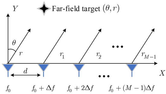
Figure 1.
Uniform FDA with linear frequency offset.
According to the narrowband assumption, , where represents the propagation delay between the target and the reference element, Equation (1) can be approximately expressed as
For ease of analysis, we first derive the case of a single-antenna receiver. Assuming the number of receiving element is 1, the signal at the receive antenna can be represented as
where represents the amplitude and phase variation caused by the electromagnetic wave propagation path and target scattering, represents the transpose operation, ⊙ represents for the Hadamard product operator, and , , , and are defined as
From (3), it can be observed that the time variable t simultaneously exists in the waveform correlation term and the beampattern correlation term , the latter of which leads to the time-varying phenomenon of the standard FDA transmit beampattern. This phenomenon not only results in the inability to concentrate the transmitted energy but also renders traditional heterodyne filtering receiver designs unsuitable for FDAs [10,28]. For this purpose, Gui et al. proposed a receiver model based on multi-channel mixing and matched filtering [18], as shown in Figure 2.
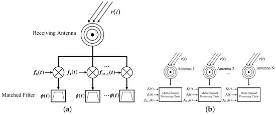
Figure 2.
Multi-channel mixing and matched filtering receiver structure of FDA. (a) Single-antenna receiver structure. (b). Multi-antenna receiver structure.
In the case of the single-antenna receiver, the output of the matched filter for the n-th channel can be expressed as
where and , with * representing the convolution operator. The definition of the ambiguity function is given as
where . From (7), the time variable t has been separated into the ambiguity function after matched filtering, and the steering vector that influences the spatial beam direction is now independent of the time variable t. However, it is important to note that couples with the spatial term and weight through a summation operation, leading to space–time coupling that can cause range measurement biases, which can result in the peak of not necessarily occurring at , thereby affecting the accurate measurement of the target’s distance. As is a function related to the envelope of the transmit waveform, it is necessary to carefully design the transmit waveform to satisfy the following decoupling condition:
where and are the time delay and Doppler tangent plane of the ambiguity function, respectively. Substituting (9) into (7), the n-th channel filter output is expressed as
By applying weighting to through the receiver beamformer, we can obtain
where is the receive weight vector of the beamformer and represents the transmit–receive steering vector matrix. In fact, and can be regarded as the cross-correlation matrix of FDA’s transmit signals.
Equation (11) is a general FDA receiving signal model, which is applicable to both FDAs with coherent transmitted waveforms and with orthogonal transmit waveforms. Consider an FDA with orthogonal transmit signal, where and where represents the diagonal matrix of . In this case, (11) can be re-expressed as
where , represents the equivalent transmit steering vector and represents the operation of taking diagonal elements.
In the multi-antenna situation, assuming that N elements are used for reception, the extension of (12) can be re-expressed as
where represents a vector of ones with N dimensions, is the reception weight vector with dimensions, ⊗ denotes the Kronecker product operator, and represents the steering vector of the receive array.
3. Null Control for FDA-MIMO Transmit–Receive Beampattern
3.1. Problem Statement
After the treatment in Section 2, the normalized transmit–receive array factor of FDA-MIMO can be represented as
In the case of an orthogonal transmit signal, the transmit weight coefficient only affects transmit power, so we do not consider optimizing . Without the loss of generality, let and define ; then, (14) can be expressed as
In the phase-only optimization of null control, two general categories of null control problems are considered [26]. The first type involves maximizing the main lobe gain while keeping the nulls in a specified region below a certain threshold value. The second type aims to minimize the null levels in a specified region while ensuring that the given main lobe gain is not less than a certain value. The corresponding optimization problems can be formulated as and :
where represents the desired null constraint level, represents the null area, and is the desired main lobe gain. Due to the presence of constant modulus constraints, both problems and are complex non-convex optimization problems and are difficult to deal with directly. Currently, there is limited research on phase-only null control based on FDAs. Classical semidefinite relaxation (SDR) techniques were employed to address the above problems in [29]; however, SDR techniques have two main drawbacks, as follows:
Firstly, SDR transforms the original vector optimization problem of dimension into a matrix optimization problem of dimension , leading to increased computational complexity.
Secondly, SDR discards the non-convex rank-one constraint, resulting in an approximate solution that may not satisfy the constant modulus constraint, necessitating further correction.
Additionally, compared to phased arrays, null control on a distance–angle 2D plane requires imposing more constraints, further increasing the computational burden of the SDR algorithm. To overcome these shortcomings, this paper introduces an efficient phase-only FDA null control technique based on the ADMM [30] in the subsequent discussion.
ADMM is a framework for solving separable convex optimization problems. It takes the form of a decomposition–composition process, where solutions to smaller local subproblems are combined to find a solution to the larger global problem. ADMM combines the advantages of dual decomposition and augmented Lagrangian methods, providing a decomposable algorithm with good convergence properties and fast processing speed. As a result, it has found widespread application in array signal processing and machine learning. Therefore, in this section, we utilize the ADMM method to solve problems and .
3.2. Solution for Based on ADMM
It can be observed that due to the presence of absolute values, the objective function of problem is not smooth. Therefore, we first introduce an auxiliary variable t that satisfies , and then we can obtain the following relationships for the objective function:
where is the upper bound for , and when the magnitude of is 1, . When , we can obtain
Equation (19) indicates that by updating t during the optimization process to satisfy , the objective function in can be transformed into a typical quadratic programming (QP) form. After the transformation given in (19), can be equivalently represented as
where is a diagonal matrix that is satisfied, as follows:
Under the ADMM algorithm framework, introducing two auxiliary variables, and , can be further equivalently represented as
where J represents the number of grid points after the discretization of the null region . Applying the ADMM algorithm framework to (23), the corresponding augmented Lagrangian function can be expressed as
where and are the dual variables, and and are penalty factors that affect the algorithm’s convergence speed. Here, and . The ADMM algorithm optimizes the variable through alternating iterative updates, and the update at the g-th iteration can be expressed as
According to (24), the closed-form update for the variable at each iteration can be derived as follows:
(1) Updating .
Solving for involves finding the extreme of an unconstrained complex-valued function, which achieves its optimal value when the gradient is zero, satisfying the following:
Clearly, can be computed as
where
Importantly, after obtaining the update for , it is necessary to update the auxiliary variable t to maintain the equivalence of the problem; thus, the g-th iteration of t can be expressed as
(2) Updating .
Solving for can be equivalently transformed into the following problem:
where . Clearly, Equation (29) is an Euclidean projection problem, and its solution for can be easily obtained as
where ⌀ represents element-wise division.
(3) Updating .
Similar to (29), the update for is also an Euclidean projection problem, and its solution is
where , and the update expressions for and are as shown in (24).
The stopping criteria for the ADMM algorithm are controlled by the primal constraint residuals , , and the dual residual , as defined in (32). Iterations are stopped when , , and are smaller than their specified thresholds.
The stopping criteria is provided for the ADMM algorithm in [30], which are
where , , and are the thresholds for the primal constraint residuals and dual residuals, and they can be represented as
where represents the absolute error tolerance and represents the relative error tolerance.
3.3. Solution for Based on DADMM
Similar to the approach in , two auxiliary variables v and are introduced to transform into a more manageable form, as follows:
The corresponding augmented Lagrangian function can be expressed as
The parameters in (36) are consistent with Equation (23). Notice the interdependence of and . Thus, is iterated as a set of variables. According to the ADMM framework, the update form for variable in the g-th iteration is given by (37).
According to Equation (37), we can derive the closed-form solution for the variable () at each iteration, as follows:
(1) Updating .
The update for is equivalent to solving the following suboptimal problem.
Equation (38) is a convex optimization problem under inequality constraints and can be solved using the Lagrange multiplier method in conjunction with the Karush–Kuhn–Tucker (KKT) conditions [31]. However, the required algebraic operations are rather complex. Therefore, this paper introduces a double-layer ADMM (DADMM) framework to further simplify this problem. The specific approach involves introducing an auxiliary variable so that (38) can be equivalently transformed as
Similarly, the augmented Lagrangian function for (39) can be derived as
where is the dual variable and is the penalty factor. According to the ADMM variable update form, the iterative forms of , and can be obtained as
Observing (41), we can see that the original inequality-constrained optimization problem (38) has been transformed into two simple unconstrained optimization problems and a straightforward Euclidean projection problem. Each step of the solution process has clear closed-form solutions, reducing the complexity of problem solving and improving efficiency. After a straightforward derivation, the iterative closed-form solutions for and in (41) are
where
Once the inner ADMM iterations stop, the output is used for the outer ADMM, and the inner ADMM iteration stopping criterion is given by
where
(2) Updating .
Solving for is likewise a simple Euclidean spherical projection problem, and its solution is consistent with (45).
(3) Updating .
According to (3-56), the problem of solving for can be formulated as
Observing (46), it can be seen that when the variable is fixed, can be regarded as a Euclidean projection problem, and the corresponding closed-form solution is given as
where . By combining (47) and (46), we can obtain an unconstrained optimization problem that depends only on , as shown below.
Since the expression of depends on , let us consider different cases for .
1. When , we can obtain , and problem (48) can be represented as
In this case, .
2. When , we can obtain , and problem (48) can be represented as
It can be observed that problem (50) is a quadratic function with respect to , and its minimum point can be expressed as
Considering the constraint on , can be calculated as
3. When , arrange in ascending order and record the indices that satisfy the condition ; then, problem (48) can be represented as
The objective function in (53) is also a quadratic function, and its minimum point in the unconstrained case is
Considering the constraint on , the optimal value can be calculated as
Thus, the update for can be completed through Equations (47), (49), (52), and (55), while the updates for the dual variables and are consistent with (37). In addition, the outer ADMM algorithm for solving problem follows the same iteration stopping criteria as solving problem in Equations (32)∼(34).
Algorithm Summary and Computational Complexity Analysis
The specific execution steps of the proposed ADMM and DADMM methods are summarized in Algorithm 1 and Algorithm 2, respectively. In the ADMM method, the main computational workload is in the updates of and in step 2, while the other steps involve only vector multiplications and divisions, resulting in a computational complexity of . Assuming that the number of iterations required for problem to converge is , the overall computational complexity is . In most cases, the value of depends on the desired level of precision in the solution.
| Algorithm 1 Algorithm of ADMM |
| Input: M, N, , , , , , , , , Output: |
In the DADMM method, the main computational workload includes the inner ADMM updates in step 2, resulting in a computational complexity of , where is the number of iterations required for inner ADMM to converge. Assuming that the number of iterations required for problem to converge is , the total computational complexity for solving problem is .
| Algorithm 2 Algorithm of DADMM |
Input:
M, N, , , , , , , , , Output:
|
4. Simulation Results
This section conducts several simulation experiments to validate the effectiveness of Algorithms 1 and 2. The simulation parameters are set as follows: the number of transmit elements , the number of receive elements , the carrier frequency GHz, the element spacing m, and the frequency offset kHz. The entire detection region is set as km km}, and the null region is defined as km km}, with sampling intervals in the range dimension and angle dimension set as km and , respectively. The desired main lobe is directed toward km). Typical phase-only optimization methods based on SDR technology are used for a performance comparison, including the Semidefinite Relaxation with Linear Constraints (SDR−LC) algorithm and the Semidefinite Relaxation with Quadratic Constraints (SDR−QC) algorithm [26]. In both SDR−LC and SDR−QC methods, a rank-one approximation method [32] is used to calculate the receive weight matrix .
4.1. Given Null Depth Constraints to Maximize the Main Lobe Gain ( Based on ADMM)
In this case, the performance of different algorithms in solving the problem of maximizing the main lobe gain under given null depth constraints is analyzed and compared. The preset null depth level is −70 dB, i.e., . Unless otherwise specified, the penalty factor is set to , and the absolute error tolerance and relative error tolerance are set to and , respectively. Figure 3 compares the transmit–receive beamforming patterns using different methods. According to Figure 3a, it can be observed that even without any optimization, the transmit–receive beampattern of the standard FDA-MIMO is decoupled in the range and angle dimension. According to Figure 3b–d, it can be seen that SDR−QC, SDR−LC, and the proposed Algorithm 1 all form lower nulls in the specified null region. To further demonstrate whether the null levels in the null region satisfy the preset null depth constraints, Figure 4 compares the projection of the null region in the direction patterns formed by different algorithms in the range dimension. It can be observed that due to the quadratic constraints used in SDR−QC, it can only describe the average null level, and the nulls formed by the SDR−QC algorithm exceed the constraint requirements in some regions, while SDR−LC and Algorithm 1 can satisfy the null depth constraints.
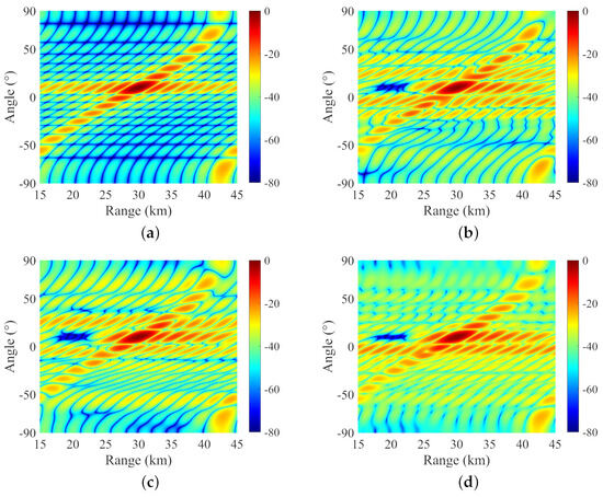
Figure 3.
Comparison of transmit–receive beampatterns using different algorithms. (a) Transmit–receive beamforming pattern of the standard FDA. (b) SDR−QC FDA. (c) SDR−LC FDA. (d) Proposed method.
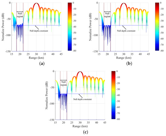
Figure 4.
Comparison of projections of null regions in beampatterns on the distance dimension. (a) SDR−QC FDA. (b) SDR−LC FDA. (c) Proposed method.
However, the SDR−LC algorithm uses linear constraints to control the null levels, and achieving precise null control in the range–angle domain requires a large number of constraints, leading to extremely high computational complexity. Unlike SDR technology, Algorithm 1 in this paper adopts the ADMM framework, which transforms the constrained optimization problem into simple unconstrained optimization problems or projection problems, avoiding the need for complex matrix operations and significantly reducing computational complexity.
Table 1 provides a detailed performance comparison between different algorithms, where the violation of the constant modulus constraint (VCMC) is defined as . From Table 1, it can be seen that Algorithm 1 requires only 0.4 s for solving problem , which is a significant performance improvement compared to 10.2 s for SDR−QC and 842 s for SDR−LC. In terms of null depth, Algorithm 1 and SDR−LC achieved −69.76 dB and −69.68 dB, respectively, which are very close to the preset level requirements. The slight error is due to the discrete approximation of the null region and the limited precision of the solution. Regarding the main lobe gain loss, SDR−LC and Algorithm 1 have similar performance, with losses of 1.02 dB and 1.01 dB, respectively, while SDR−QC has a relatively smaller main lobe gain loss of 0.92 dB, which is a result of the trade-off between antenna main lobe gain and sidelobe performance.

Table 1.
Performance comparison of different null control algorithms.
Examining the performance parameters of various algorithms in Table 1, it appears that the algorithm proposed in this paper holds an advantage solely in computational efficiency. However, it is noteworthy that Algorithm 1 exhibits significantly lower violation of the constant modulus constraint compared to the SDR−QC and SDR−LC algorithms. In fact, due to the highly dimensional receiving weight matrix in the FDA-MIMO, solutions obtained by SDR−LC and SDR−QC using rank-one approximation often contain numerous violations of the constant modulus constraint. Figure 5 compares the weights obtained with different algorithms, clearly revealing that both SDR−LC and SDR−QC have instances where the modulus values are not equal to 1. If the weight decreases, it will result in signal power loss [33], thereby reducing the effective range of the system. However, the constant modulus constraint can effectively reduce signal loss. It is easy to imagine that if the weights obtained with SDR−QC and SDR−LC are reset to 1, the performance of the beampattern will decrease significantly. The null performance of the beampattern after setting the weights to 1 is shown in Table 2. It can be observed that, under precise constant modulus constraints, SDR−QC and SDR−LC methods can only maintain null levels of −42.41 dB and −46.87 dB, respectively, significantly exceeding the prescribed null depth requirement of −70 dB. In contrast, Algorithm 1 proposed in this paper, by maintaining precise constant modulus constraints, preserves the original performance. In contrast, Algorithm 1 consistently ensures the constant modulus constraint, representing another advantage of the proposed algorithm over SDR−QC and SDR−LC.
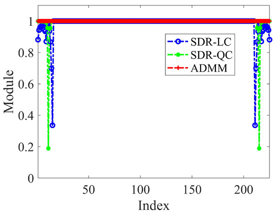
Figure 5.
Comparison of modulus values for receiving weights obtained with different algorithms.

Table 2.
Performance comparison of different algorithms after projection onto feasible solution space.
To illustrate the convergence process of Algorithm 1 in this paper, Figure 6 depicts the curves of the objective function and constraint variations. From Figure 6a, it is evident that the objective function rapidly decreases and then gradually increases, reaching an extremely low level within 30 iterations, demonstrating the excellent convergence capability of Algorithm 1. In Figure 6b, it can be observed that the constraint conditions are constantly approached as the iteration progresses, which is also the reason for the subsequent gradual increase in the objective function.
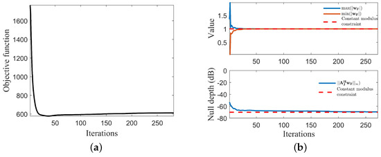
Figure 6.
The curves depicting changes in the objective function and constraints. (a) The evolution of the objective function. (b) The evolution of constraint changes.
Additionally, to validate the impact of different penalty factors on the convergence of the proposed algorithm, Figure 7 provides the curves of the objective function variation for different values of the penalty factors and . It can be observed that a smaller penalty factor leads to a faster convergence. However, it is important to note that the penalty factor should not be set too small as this may result in the algorithm failing to converge [34].
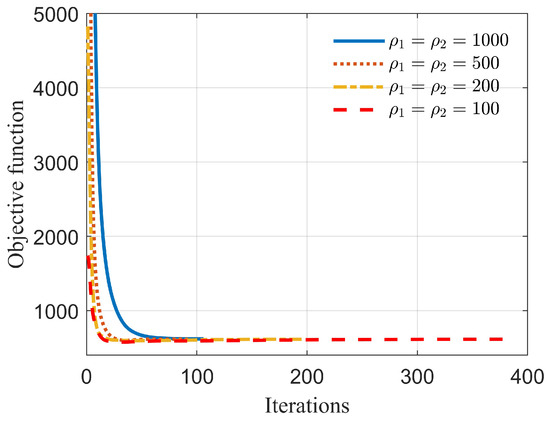
Figure 7.
Comparison of objective function variation curves under different penalty factors.
4.2. Maximizing Null Depth under Given Main Lobe Gain Constraint ( Based on DADMM)
In this section, an analysis and comparison of the performance of different algorithms in solving the problem of maximizing null depth under a given main lobe gain constraint were conducted. Unless otherwise specified, the penalty factors were set as and , and the main lobe gain constraint was denoted as , indicating a main lobe loss of 0.92 dB. Figure 8 provides a comprehensive comparison of the beampatterns generated using different algorithms. It can be observed that the null depths formed by Algorithm 2 in this paper and the SDR−LC algorithm are comparable and superior to the SDR−QC method. Both Algorithm 2 and SDR−LC achieved precise control of null responses, which is crucial in certain radar-communication integration applications. On the other hand, the null region levels in SDR−QC exhibited noticeable fluctuations.
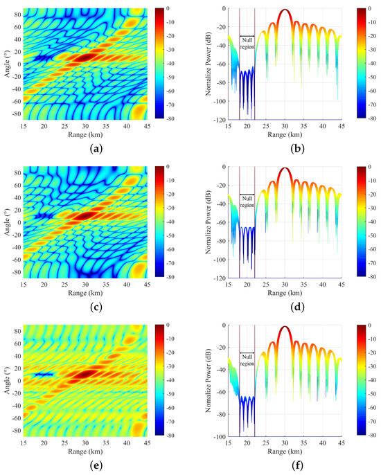
Figure 8.
Beampattern comparison of different null control algorithms. (a) SDR−QC beampattern projection in distance–angle domain. (b) SDR−QC beampattern projection in distance domain. (c) SDR−LC beampattern projection in distance–angle domain. (d) SDR−LC beampattern projection in distance domain. (e) Proposed method beampattern projection in distance−angle domain. (f) Proposed method beampattern projection in distance domain.
Table 3 provides a detailed comparison of the performance of different algorithms. The proposed Algorithm 2 still exhibits the highest computational efficiency in solving such problems, with a runtime of only 1.2 s, while SDR−QC and SDR−LC require 9.28 s and 560 s, respectively. Due to the presence of the main lobe gain constraint, SDR−QC, SDR−LC, and Algorithm 2 all achieve consistent main lobe gain performance. However, in terms of null depth, Algorithm 2 in this paper is slightly lower than SDR−QC and SDR−LC. As analyzed in , this phenomenon is attributed to the disruption of constant modulus constraints by SDR−QC and SDR−LC methods. Figure 9 illustrates the modulus values of weights obtained with different algorithms. It can be observed that SDR−QC and SDR−LC have numerous violations of the constant modulus constraint, while Algorithm 2 in this paper consistently maintains the constant modulus constraint. Table 4 presents a performance comparison after projecting different algorithms into the feasible solution space. Due to the enforced constant modulus constraint, the SDR−QC and SDR−LC methods can only maintain null levels of −22.31 dB and −22.51 dB, respectively, whereas Algorithm 2 in this paper still maintains its original performance. It is worth mentioning that both the FDA-MIMO beampatterns synthesized by both the ADMM and the DADMM methods, as shown in Figure 3 and Figure 8, show an increase in sidelobe regions. This is caused by the addition of null region, which introduces additional phase distortions or oscillations. For practical antenna applications, designers can add threshold conditions for the sidelobe level as constraints in problems and to meet different application requirements. Additionally, it is worth noting that random and unnecessary fluctuations during the matched filtering process can interfere with the phase of the ideal reference signal [35]. Our theoretical derivations have neglected this impact. We plan to introduce phase noise in our future research and further study FDA-MIMO null control under phase noise conditions.

Table 3.
Performance comparison of different null control algorithms.
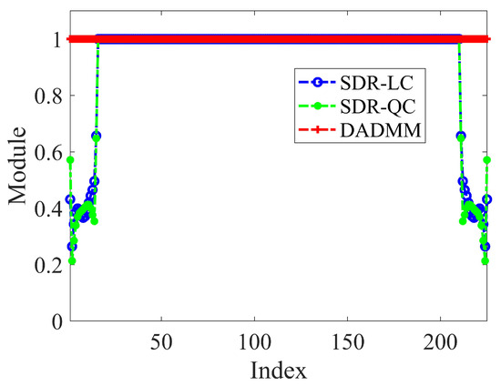
Figure 9.
Comparison of modulus values for receiving weights obtained with different algorithms.

Table 4.
Performance comparison of different algorithms after projection onto feasible solution space.
5. Conclusions
This paper focuses on the research of null control in the transmit–receive beampattern of phased array antennas. It begins by deriving the signal model for the phased array receiver, establishing the model for null control in the transmit–receive beampattern of the FDA-MIMO system. Based on this, a phase-only optimization approach for null control in the FDA-MIMO system is proposed using the ADMM algorithm. This method addresses the challenges of the hardware complexity and computational load associated with the high dimensionality of FDA-MIMO null control by adopting a phase-only optimization strategy to reduce hardware complexity. Subsequently, the ADMM framework is employed to solve this constant modulus constraint optimization problem. Numerical experimental results demonstrate that the proposed algorithm exhibits a superior null control capability, precise constant modulus constraint retention ability, and extremely high computational efficiency. In our future work, we will test the effectiveness of the algorithm using real recorded interference signals to further validate its practical applicability.
Author Contributions
Methodology, M.X.; Software, M.X., X.S. and Y.W.; Validation, M.X.; Writing—original draft, M.X.; Writing—review & editing, T.H., X.S., Y.W. and Z.X.; Supervision, T.H. All authors have read and agreed to the published version of the manuscript.
Funding
This research received no external funding.
Data Availability Statement
The original contributions presented in the study are included in the article, further inquiries can be directed to the corresponding author.
Conflicts of Interest
The authors declare no conflicts of interest.
References
- Steyskal, H.; Shore, R.; Haupt, R. Methods for null control and their effects on the radiation pattern. IEEE Trans. Antennas Propag. 1986, 34, 404–409. [Google Scholar] [CrossRef]
- Lan, L.; Liao, L.; Xu, J.; Zhu, S.; Zeng, C.; Zhang, Y. Control and utilization of range-dependent beampattern with waveform diverse array radars. Chin. J. Aeronaut. 2022, 35, 1–31. [Google Scholar] [CrossRef]
- Liu, Z.; Zhao, S.; Zhang, G.; Jiao, B. Robust adaptive beamforming for sidelobe canceller with null widening. IEEE Sensors J. 2019, 19, 11213–11220. [Google Scholar] [CrossRef]
- Liu, Z.; Zhao, S.; Zhang, C.; Zhang, G. Flexible robust adaptive beamforming method with null widening. IEEE Sensors J. 2021, 21, 10579–10586. [Google Scholar] [CrossRef]
- Zhang, L.; Li, B.; Huang, L.; Kirubarajan, T.; So, H.C. Robust minimum dispersion distortionless response beamforming against fast-moving interferences. Signal Process. 2017, 140, 190–197. [Google Scholar] [CrossRef]
- Amar, A.; Doron, M.A. A linearly constrained minimum variance beamformer with a pre-specified suppression level over a pre-defined broad null sector. Signal Process. 2015, 109, 165–171. [Google Scholar] [CrossRef]
- Mao, X.; Li, W.; Li, Y.; Sun, Y.; Zhai, Z. Robust adaptive beamforming against signal steering vector mismatch and jammer motion. Int. J. Antennas Propag. 2015, 2015, 780296. [Google Scholar] [CrossRef]
- Antonik, P.; Wicks, M.C.; Griffiths, H.D.; Baker, C.J. Frequency diverse array radars. In Proceedings of the 2006 IEEE Conference on Radar, Verona, NY, USA, 24–27 April 2006; p. 3. [Google Scholar]
- Wang, W.Q. Frequency diverse array antenna: New opportunities. IEEE Antennas Propag. Mag. 2015, 57, 145–152. [Google Scholar] [CrossRef]
- Tan, M.; Wang, C.; Li, Z. Correction analysis of frequency diverse array radar about time. IEEE Trans. Antennas Propag. 2020, 69, 834–847. [Google Scholar] [CrossRef]
- Gong, P.; Wang, W.Q.; Li, F.; So, H.C. Sparsity-aware transmit beamspace design for FDA-MIMO radar. Signal Process. 2018, 144, 99–103. [Google Scholar] [CrossRef]
- Wen, C.; Huang, Y.; Peng, J.; Wu, J.; Zheng, G.; Zhang, Y. Slow-time FDA-MIMO technique with application to STAP radar. IEEE Trans. Aerosp. Electron. Syst. 2021, 58, 74–95. [Google Scholar] [CrossRef]
- Huang, B.; Basit, A.; Gui, R.; Wang, W.Q. Adaptive moving target detection without training data for FDA-MIMO radar. IEEE Trans. Veh. Technol. 2021, 71, 220–232. [Google Scholar] [CrossRef]
- Basit, A.; Wang, W.Q.; Wali, S.; Nusenu, S.Y. Transmit beamspace design for FDA–MIMO radar with alternating direction method of multipliers. Signal Process. 2021, 180, 107832. [Google Scholar] [CrossRef]
- Xu, Y.; Luk, K.M. Enhanced transmit–receive beamforming for frequency diverse array. IEEE Trans. Antennas Propag. 2020, 68, 5344–5352. [Google Scholar] [CrossRef]
- Xu, Y.; Wang, A.; Xu, J. Range–Angle Transceiver Beamforming Based on Semicircular-FDA Scheme. IEEE Trans. Aerosp. Electron. Syst. 2021, 58, 834–843. [Google Scholar] [CrossRef]
- Wang, C.; Zhu, X.; Huang, S. Coherent receiver design and aperture expansion beamforming for frequency diverse array radar. Digit. Signal Process. 2022, 128, 103631. [Google Scholar] [CrossRef]
- Gui, R.; Wang, W.Q.; Cui, C.; So, H.C. Coherent pulsed-FDA radar receiver design with time-variance consideration: SINR and CRB analysis. IEEE Trans. Signal Process. 2017, 66, 200–214. [Google Scholar] [CrossRef]
- Lan, L.; Rosamilia, M.; Aubry, A.; De Maio, A.; Liao, G. FDA-MIMO Transceiver Design under the Uniform Frequency Increment Constraint. IEEE Trans. Radar Syst. 2024, 2, 446–459. [Google Scholar] [CrossRef]
- Liao, Y.; Tang, H.; Chen, X.; Wang, W.Q.; Xing, M.; Zheng, Z.; Wang, J.; Liu, Q.H. Antenna beampattern with range null control using weighted frequency diverse array. IEEE Access 2020, 8, 50107–50117. [Google Scholar] [CrossRef]
- Ding, Z.; Xie, J.; Wang, B.; Zhang, H. Robust adaptive null broadening method based on FDA-MIMO radar. IEEE Access 2020, 8, 177976–177983. [Google Scholar] [CrossRef]
- Lan, L.; Xu, J.; Liao, G.; Zhang, Y.; Fioranelli, F.; So, H.C. Suppression of mainbeam deceptive jammer with FDA-MIMO radar. IEEE Trans. Veh. Technol. 2020, 69, 11584–11598. [Google Scholar] [CrossRef]
- Lan, L.; Liao, G.; Xu, J.; Zhang, Y.; Liao, B. Transceive beamforming with accurate nulling in FDA-MIMO radar for imaging. IEEE Trans. Geosci. Remote. Sens. 2020, 58, 4145–4159. [Google Scholar] [CrossRef]
- Lan, L.; Liao, G.; Xu, J.; Zhu, S.; Zhang, Y. Range-angle-dependent beamforming for FDA-MIMO radar using oblique projection. Sci. China Inf. Sci. 2022, 65, 152305. [Google Scholar] [CrossRef]
- Smith, S.T. Optimum phase-only adaptive nulling. IEEE Trans. Signal Process. 1999, 47, 1835–1843. [Google Scholar] [CrossRef]
- Kajenski, P.J. Phase only antenna pattern notching via a semidefinite programming relaxation. IEEE Trans. Antennas Propag. 2012, 60, 2562–2565. [Google Scholar] [CrossRef]
- Pallotta, L.; Farina, A.; Smith, S.T.; Giunta, G. Phase-only space-time adaptive processing. IEEE Access 2021, 9, 147250–147263. [Google Scholar] [CrossRef]
- Tan, M.; Wang, C. Reply to Comments on “Correction Analysis of ‘Frequency Diverse Array Radar about Time’”. IEEE Trans. Antennas Propag. 2022, 71, 2899–2902. [Google Scholar] [CrossRef]
- Chen, G.; Wang, C.; Gong, J.; Tan, M.; Liu, Y. Data-Independent Phase-Only Beamforming of FDA-MIMO Radar for Swarm Interference Suppression. Remote Sens. 2023, 15, 1159. [Google Scholar] [CrossRef]
- Boyd, S.; Parikh, N.; Chu, E.; Peleato, B.; Eckstein, J. Distributed optimization and statistical learning via the alternating direction method of multipliers. Found. Trends® Mach. Learn. 2011, 3, 1–122. [Google Scholar]
- Karush, W. Minima of Functions of Several Variables with Inequalities as Side Constraints. Master’s Thesis, Department of Mathematics, The University of Chicago, Chicago, IL, USA, 1939. [Google Scholar]
- Luo, Z.Q.; Ma, W.K.; So, A.M.C.; Ye, Y.; Zhang, S. Semidefinite relaxation of quadratic optimization problems. IEEE Signal Process. Mag. 2010, 27, 20–34. [Google Scholar] [CrossRef]
- He, X.; Wang, J. QCQP with extra constant modulus constraints: Theory and application to SINR constrained mmwave hybrid beamforming. IEEE Trans. Signal Process. 2022, 70, 5237–5250. [Google Scholar] [CrossRef]
- Liu, Y.; Jiu, B.; Liu, H. ADMM-based transmit beampattern synthesis for antenna arrays under a constant modulus constraint. Signal Process. 2020, 171, 107529. [Google Scholar] [CrossRef]
- Aubry, A.; De Maio, A.; Carotenuto, V.; Farina, A. Radar phase noise modeling and effects-part I: MTI filters. IEEE Trans. Aerosp. Electron. Syst. 2016, 52, 698–711. [Google Scholar] [CrossRef]
Disclaimer/Publisher’s Note: The statements, opinions and data contained in all publications are solely those of the individual author(s) and contributor(s) and not of MDPI and/or the editor(s). MDPI and/or the editor(s) disclaim responsibility for any injury to people or property resulting from any ideas, methods, instructions or products referred to in the content. |
© 2024 by the authors. Licensee MDPI, Basel, Switzerland. This article is an open access article distributed under the terms and conditions of the Creative Commons Attribution (CC BY) license (https://creativecommons.org/licenses/by/4.0/).