3.1. Pulse Parameter Extraction of Radar Echo Signal
Based on the plasma flow-field data of the blunt cone aircraft at the height of 40 km, the maximum reflection intensity and coupled Doppler frequency of the radar echo are calculated at each reference point after it is perpendicular to the incident plasma flow field on the surface of the aircraft. The plasma flow-field parameters and radar signal parameters are shown in
Table 1. By referring to the aforementioned Equations (13) and (15), the transmitted signal and the time-domain radar echo signal are simulated, and a convolution operation is conducted with respect to the echo signal based on the DOB filter to extract the echo’s start time. Considering the target-to-radar range, we also analyzed the relationship between the start time and the time delay.
As shown in
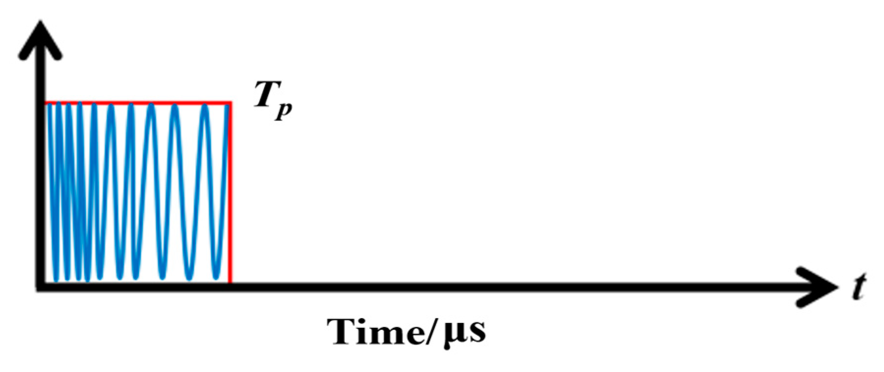
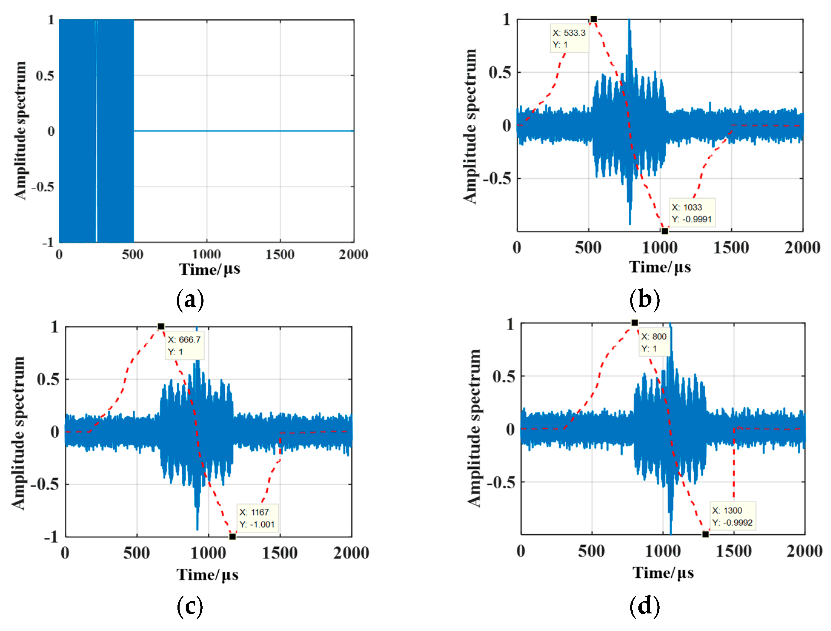
Figure 7, the red dotted line indicates results from the echo signal output through the DOB filter. It can be observed that the three target-to-radar ranges differ, and the offset caused by the time-domain echo signal differs accordingly. The transmitted signal possesses 500 μs pulse width, 0 μs start time, and 500 μs end time, respectively.
When the target-to-radar range is 80 km, the echo’s time delay is computed to be 533.3 μs using Equation (17). The DOB filter processes the echo to form two peaks in the time domain. The start time of the echo measured by the method proposed in this paper is 533.3 μs, which is consistent with the theoretical value. The echo’s end time is 1033.4 μs, and its pulse width is estimated to be 20.01 μs throughout the start and end times, in which the error with the actual pulse width is 0.02%. When the target-to-radar range is 100 km, the time delay generated by the target is 666.7 μs. The output maximum peak position based on the DOB filter is 666.7 μs, which is consistent with the time delay caused by the target, in which the error between the echo’s pulse width and the actual pulse width is 0.02%. When the target-to-radar range is 120 km, the target time delay is 800 μs. The DOB output result of the echo is consistent with the actual delay of the target, and the error between the estimated pulse width of the echo and the actual pulse width is 0.02%.
It can be acknowledged that the start time of the echo can be extracted based on DOB filter processing, and the echo’s time delay can be obtained.
3.2. I-D Frequency Extraction of Echo Signals
The existence of the difference in spatial distribution of the PSh suggests that the echo and the multi-I-D frequency components will be coupled. In this section, based on the simulated radar echo signal in
Section 3.1, we analyze the inadequate conventional time-frequency processing method (WVD, fractional Fourier transform (FRFT)) to extract the I-D frequency. According to Equations (14), (29), and (35), the simulated radar echo signal is processed, and the frequency extraction method was verified. In this section, the target distance of the simulated echo is 100 km, and other simulation parameters are consistent with those in
Section 3.1.
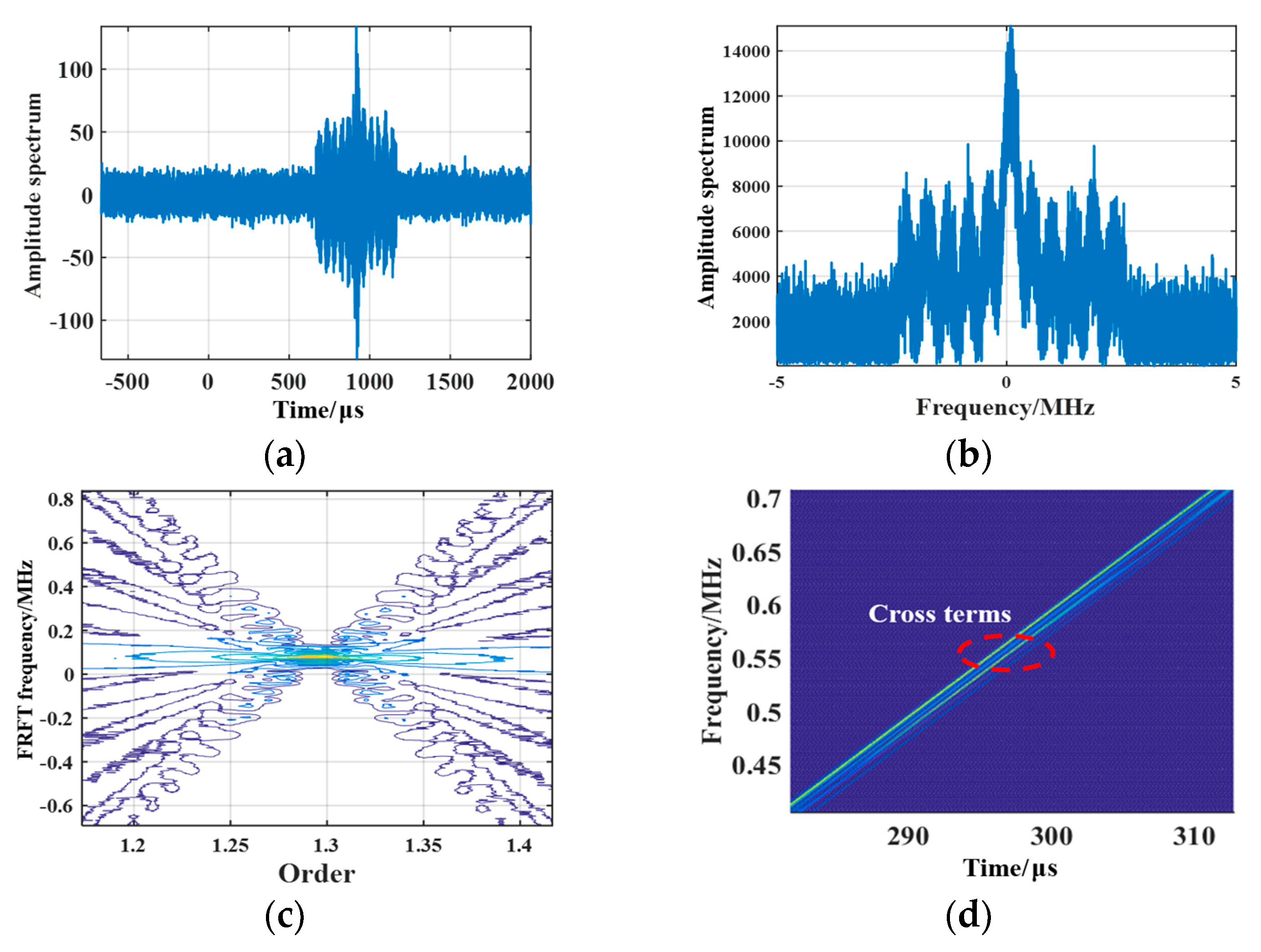
It can be observed from
Figure 8a that since the I-D frequencies of the echo (the target echo signal at the same range) differ, the time-domain echo signal is distorted, causing a “periodic dispersion” phenomenon. Additionally, we observe from
Figure 8b that a significant modulation phenomenon occurs in the frequency-domain echo signal, and a serious “oscillation” phenomenon appears in the bandwidth.
We observe from
Figure 8c that the energy of the FRFT transformation results distributes on a straight line. The FRFT transform of the echo is limited by the frequency resolution. When the I-D frequencies are closely coupled in the echo, energy aliasing will occur, under which circumstance the peak position will expand, preventing the I-D frequency from being extracted effectively.
Furthermore,
Figure 8d demonstrates that some slant lines occur in a two-dimensional time-frequency plane of Wigner–Ville transform results of the echo signals, which have the same slope and intercepts (the same modulation frequency and different carrier frequencies). Because of the existence of multiple I-D frequency components in the echo, the time-frequency curve contains many cross terms, causing errors in the extraction results of the I-D frequency.
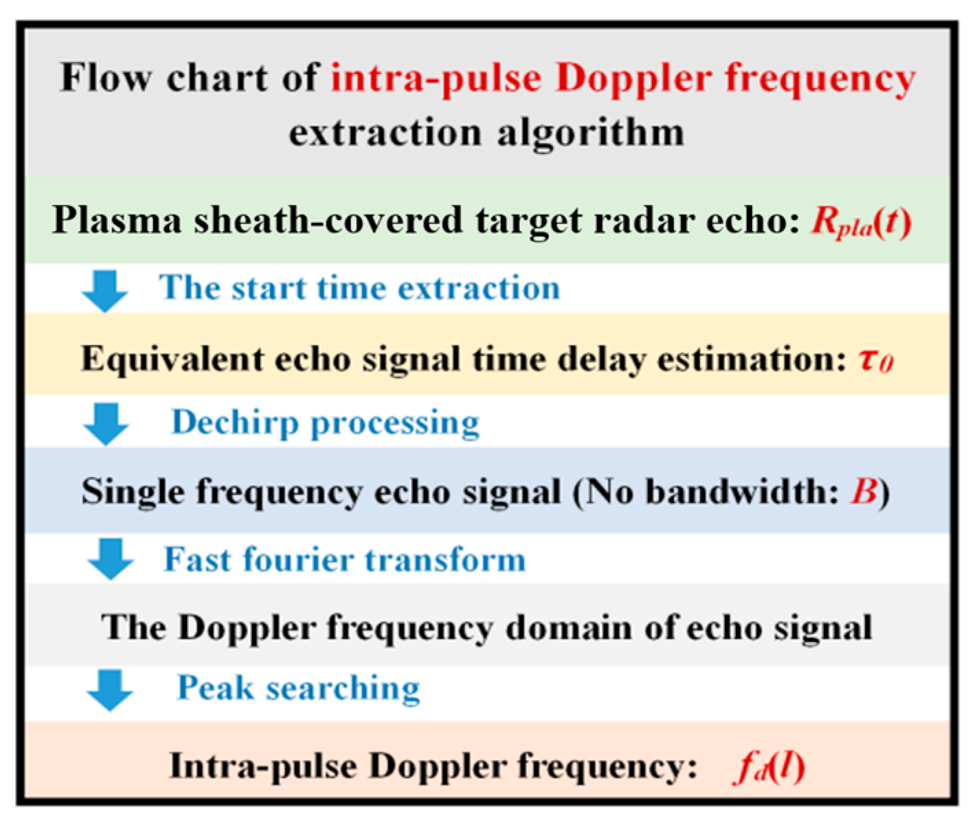
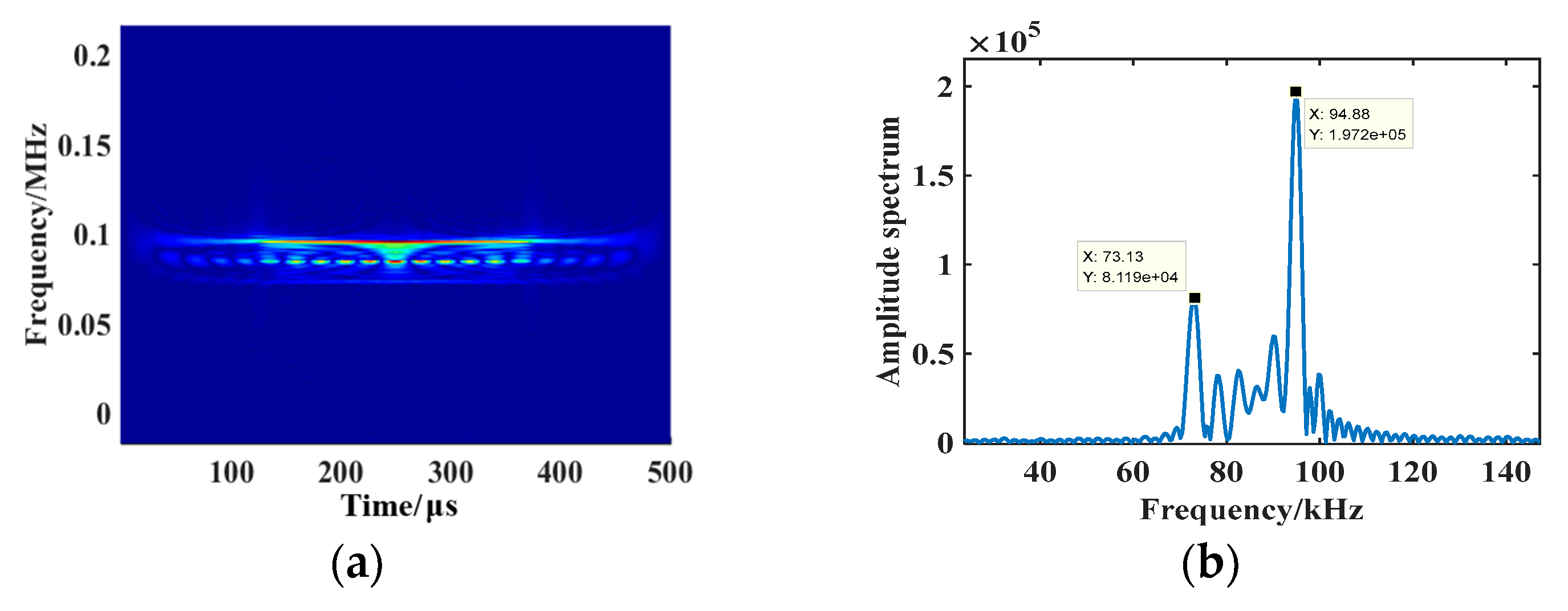
Figure 9a suggests that when the echo is dechirp-processed, its time-frequency curve is a straight line perpendicular to the frequency axis. According to Equation (32), the dechirp processing can effectively eliminate the modulation frequency
u of the echo, for which reason the signal only contains the carrier frequency information.
Figure 9b demonstrates that the frequency-domain characteristics of the dechirp-processed echo can be obtained by Fourier transform. Since the modulation frequency of the echo is eliminated, no influence will be exerted on the bandwidth in the frequency domain (the echo signal is transformed from a LFM signal to a single carrier frequency signal). There are several significant peaks in the frequency spectrum, and the peak positions correspond to the signal carrier frequency.
Table 2 shows that under the circumstance of the same parameters, our proposed method is capable of extracting the minimum frequency interval, which is only 0.0657 MHz. Since the I-D frequency is usually low and the intra-pulse frequency components are relatively close to each other, our proposed method can effectively extract the I-D frequency of the coupled echo signal. Additionally, the method exhibits very low computational complexity, and its operation time is much less than the other two methods under the same circumstances. The critical SNR, for which this method can effectively extract the minimum frequency interval, is −9 dB, whereas the critical SNRs of the other two methods are −12 dB and −10 dB, respectively. The critical SNR of our proposed method in this study is a bit higher than the other two methods. One reasonable explanation is that our proposed method needs to estimate the pulse parameters. A SNR that is too low reduces the estimation accuracy of the pulse parameters and causes similar I-D frequencies to be easily aliased due to noise.
3.3. Velocity Distribution Characteristics of the PSh
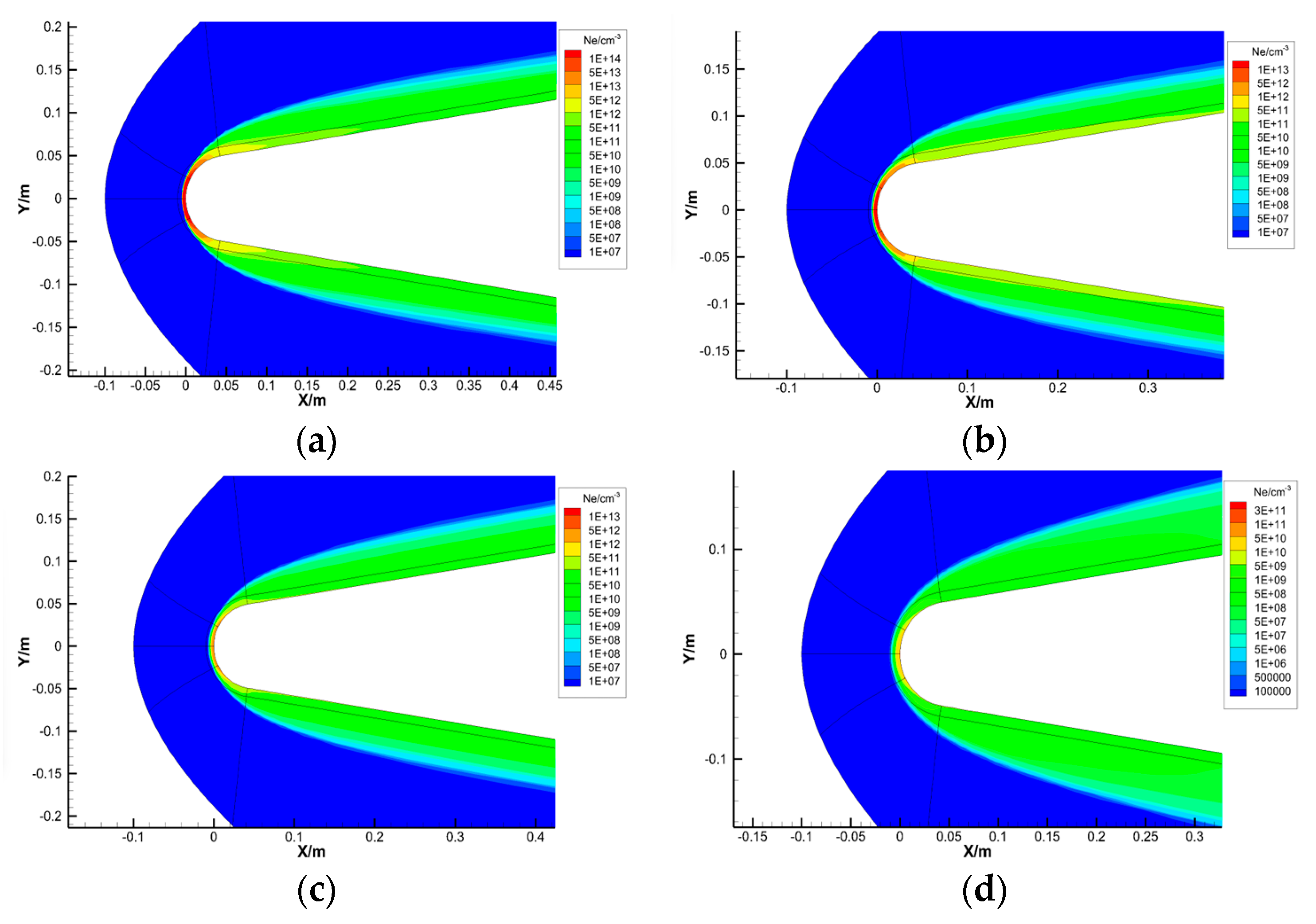
Based on the simulated flow-field data of the conical target at different heights, this subsection analyzes the distribution characteristics of the velocity of the plasma flow field under circumstances of typical aircraft flight velocity (V = 24 Mach, 1 Mach = 340 m/s) and different flight altitudes (H = 30 km~70 km). The electron density distribution of the simulated flow field of the cone aircraft at different altitudes is shown in
Figure 10.
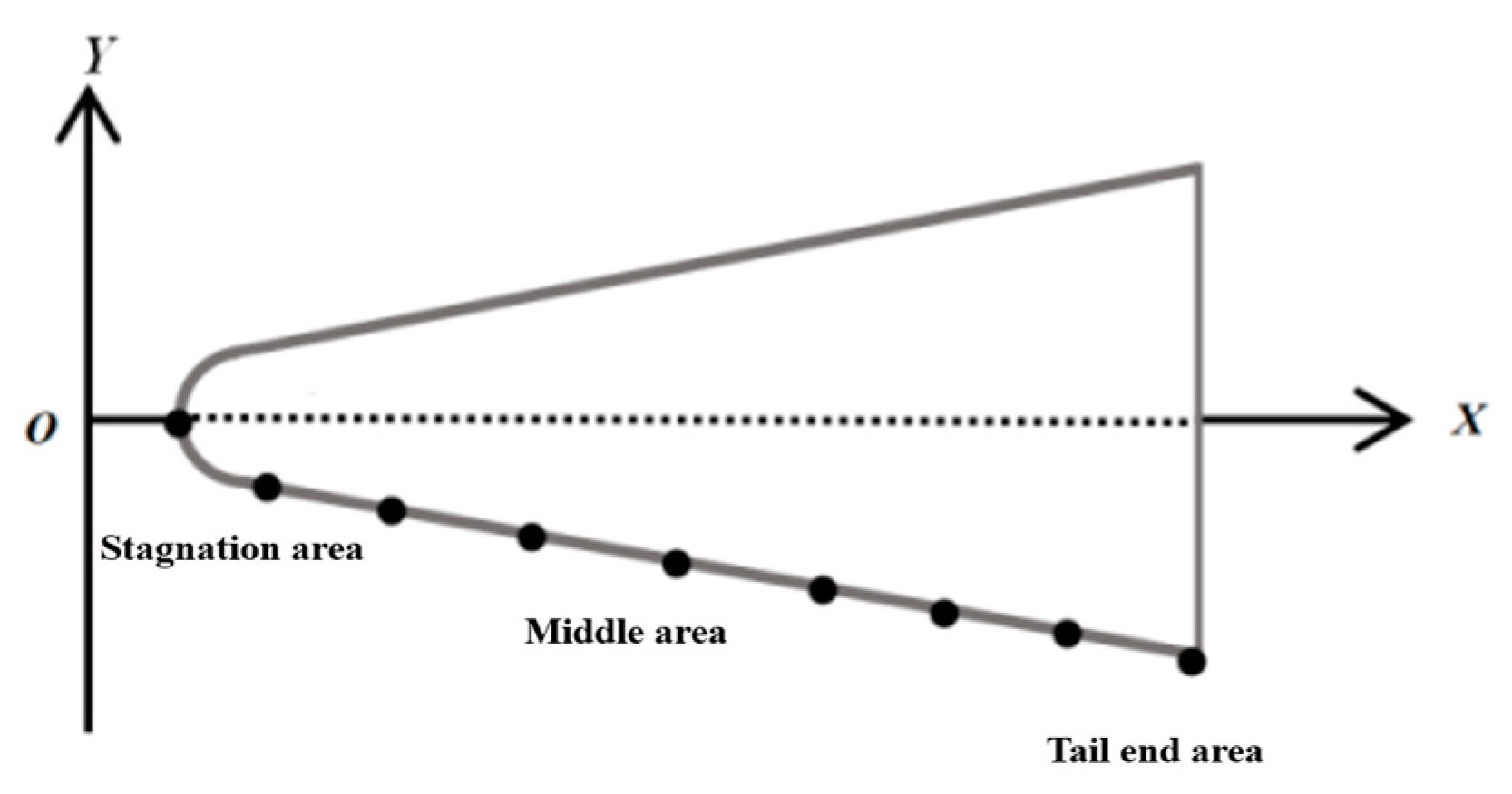
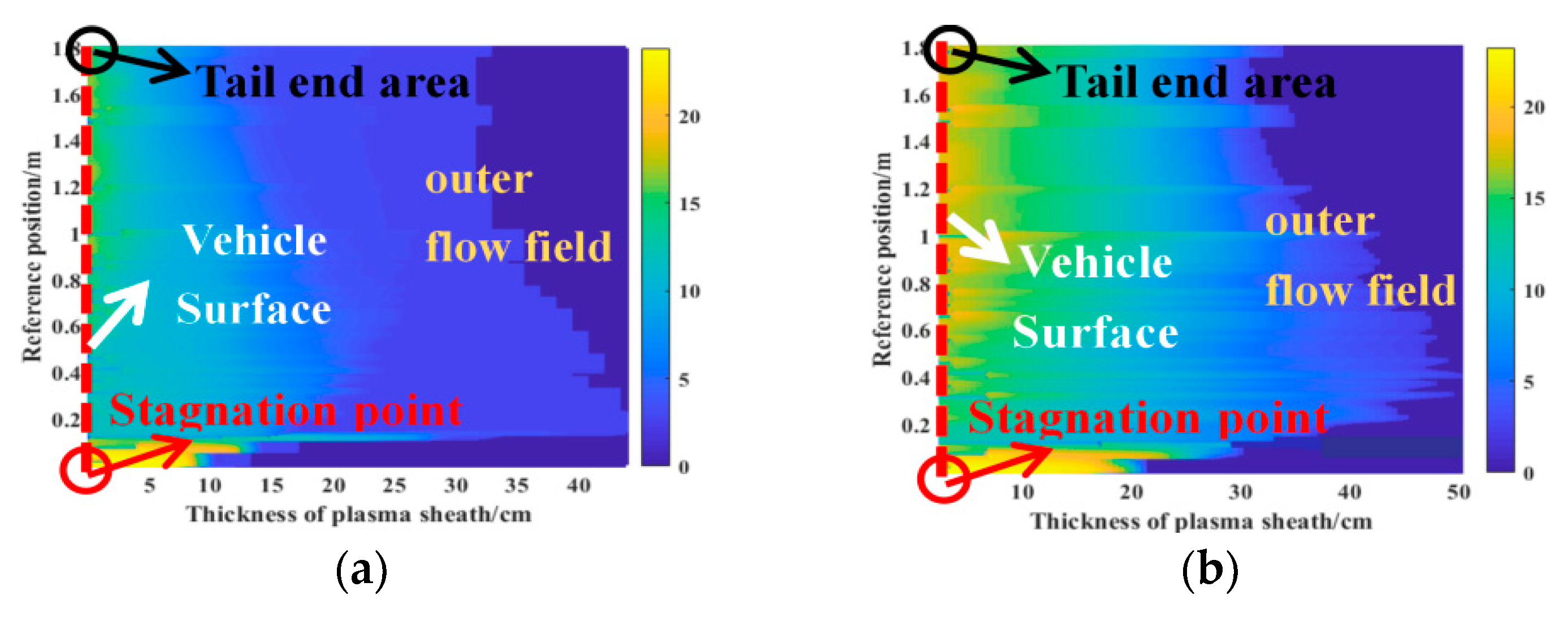
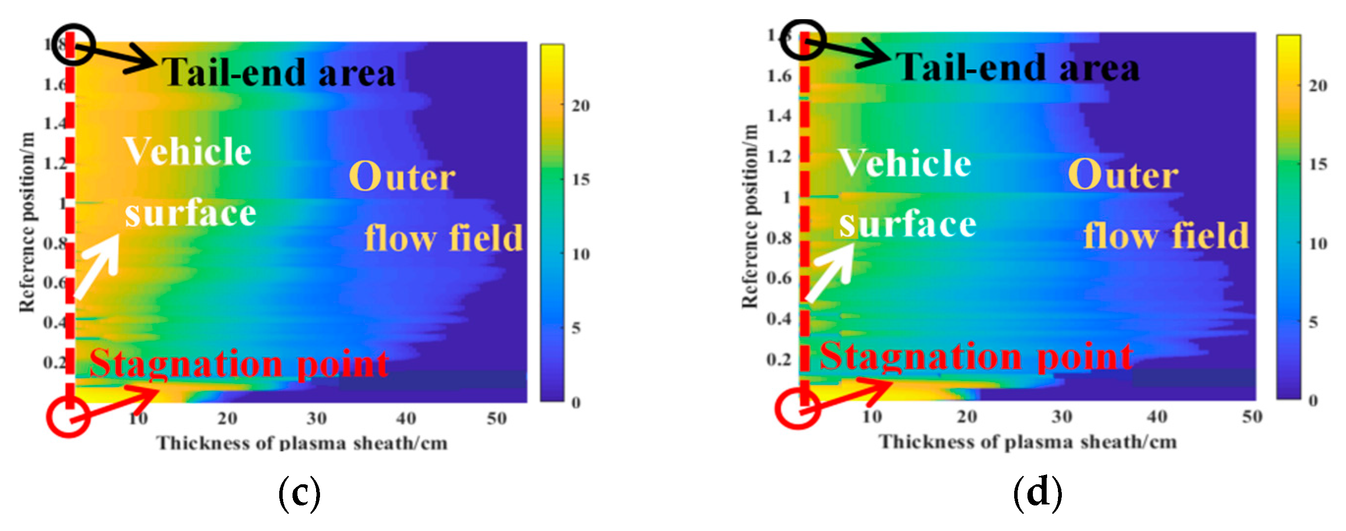
Figure 11a–d respectively represent the velocity distribution characteristics of the plasma flow field at four altitudes. The red dashed line represents the vehicle surface. The plasma is produced within the stagnation point area of the vehicle. Influenced by the action of high-velocity incoming flow, the plasma moves along the stagnation point area to the tail-end area and forms a PSh enveloping the vehicle. As a result, the spatial distribution of the plasma flow velocity varies significantly within different reference areas.
At 30 km altitude, the innermost flow-field velocity of the PSh is similar to the actual velocity of the vehicle. Vertically outward along the vehicle surface, the flow-field velocity declines mildly. The velocity of the outer flow field decreases faster than that of the inner flow field, and the velocity of the outer flow field is far lower than the vehicle velocity. Within the area of the stagnation point, the inner flow-field velocity has an approximately uniform distribution, but the outer flow-field velocity sharply decreases. From the area of the stagnation point to that of the tail end, the velocity distribution interval of the plasma flow field first increases and then decreases, while the velocity descending gradient decreases accordingly.
As shown in
Figure 10, with the increase in flight altitude, the electron density of the flow field decreases, but the thickness of the plasma sheath also increases accordingly. At the position close to the vehicle surface, the range of the flow field whose velocity is close to the target velocity gradually increases. The descending gradient of the flow-field velocity within the stagnation point area is approximately constant, the descending gradient of the flow-field velocity in the middle area and the tail-end area decreases.
3.4. Variation Law of the Coupled I-D Frequency in an Echo Signal under Typical Parameters
According to the aforementioned computation results, this subsection analyzes the coupled I-D frequency in the echo signal of the PSh-enveloped target and reveals the variation law of the I-D frequency through different carrier frequencies (fc = 3.3 GHz, 5.8 GHz, 9.5 GHz, and 18 GHz) and different flight altitudes (H = 30 km, 50 km, 60 km, and 70 km).
At the flight altitude of 30 km:
Figure 12.
Reflection coefficient of plasma sheath to electromagnetic wave at an altitude of 30 km: (a) fc = 3.3 GHz; (b) fc = 5.8 GHz; (c) fc = 9.5 GHz; (d) fc = 18 GHz.
Figure 12.
Reflection coefficient of plasma sheath to electromagnetic wave at an altitude of 30 km: (a) fc = 3.3 GHz; (b) fc = 5.8 GHz; (c) fc = 9.5 GHz; (d) fc = 18 GHz.
Figure 13.
The Doppler spectrum of the echo at an altitude of 30 km: (a) fc = 3.3 GHz; (b) fc = 5.8 GHz; (c) fc = 9.5 GHz; (d) fc = 18 GHz.
Figure 13.
The Doppler spectrum of the echo at an altitude of 30 km: (a) fc = 3.3 GHz; (b) fc = 5.8 GHz; (c) fc = 9.5 GHz; (d) fc = 18 GHz.
It can be observed that the relative motion of the PSh causes the echo signal to couple with different I-D frequencies. As can be seen from
Figure 12, at an altitude of 30 km, with the increase in carrier frequency, the strongest reflection positions of electromagnetic waves in the plasma sheath are all in the outer layer of the PSh. At this time, the plasma sheath has a strong shielding effect on electromagnetic waves. As can be seen from
Figure 11a, when the flight altitude of the aircraft is 30 km, the velocity outside the PSh is more than 10 Mach lower than the target flight velocity. Therefore, the Doppler frequency coupled with the outside of the PSh is much lower than the Doppler frequency corresponding to the target velocity.
Figure 13a suggests that when the carrier frequency is 3.3 GHz, the maximum I-D frequency coupled in the echo signal is 0.1244 MHz, under which circumstance the corresponding velocity is 16.6 Mach. Because of the extremely high electron density at this flight altitude (the peak characteristic frequency of the plasma flow field within the tail-end area is 23 GHz, which exceeds the radar signal’s carrier frequency), the wave incident depth remains approximately unchanged as the carrier frequency (5.8 GHz, 9.5 GHz, and 18 GHz) increases, under which circumstance the velocity corresponding to the maximum I-D frequency coupled in the echo signal approximates 17 Mach.
At the flight altitude of 50 km:
Figure 14.
The Doppler spectrum of the echo at an altitude of 50 km: (a) fc = 3.3 GHz; (b) fc = 5.8 GHz; (c) fc = 9.5 GHz; (d) fc = 18 GHz.
Figure 14.
The Doppler spectrum of the echo at an altitude of 50 km: (a) fc = 3.3 GHz; (b) fc = 5.8 GHz; (c) fc = 9.5 GHz; (d) fc = 18 GHz.
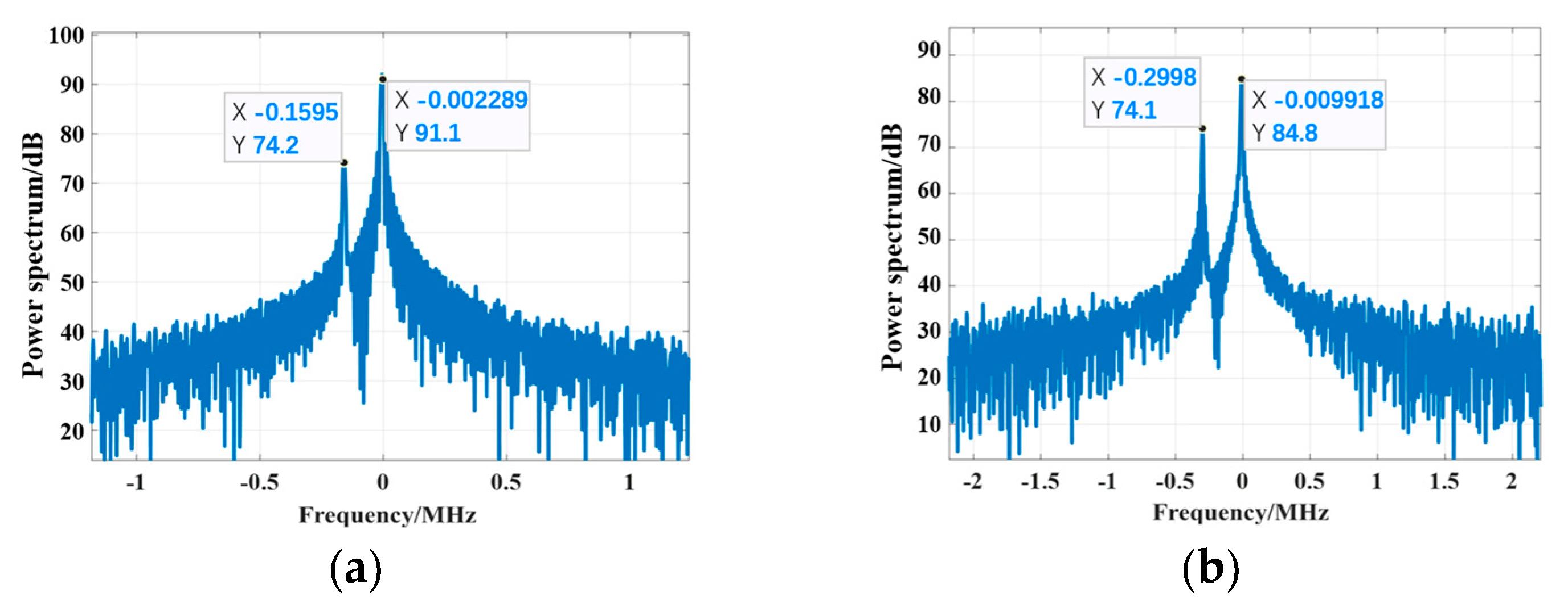
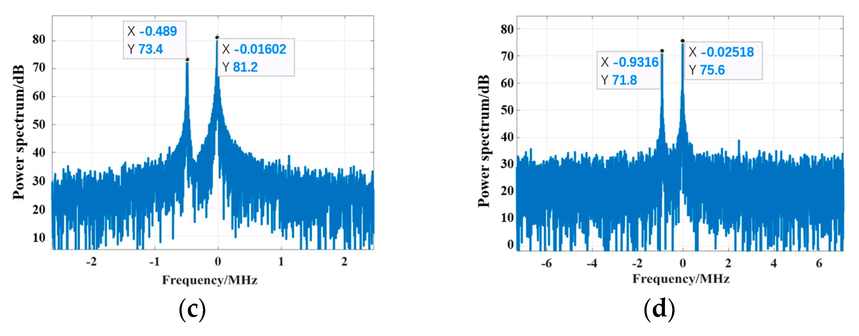
At 50 km altitude, the electron density decreases, the PSh shielding effect imposed on the wave degrades, and the incident depth increases. As shown in
Figure 14, when the carrier frequency is 3.3 GHz, the maximum I-D frequency coupled in the echo signal is 0.1595 MHz, for which the corresponding velocity is 21.3 Mach, and the maximum peak energy is 91 dB. When the carrier frequency increases to 5.8 GHz and 9.5 GHz, the maximum I-D frequency coupled in the echo signal increases. This is because the incident depth increases, while the velocity corresponding to the maximum I-D frequency is 22.5 Mach. As the incident depth continues to increase, the secondary energy absorption effect of the PSh exerted on the echo signal intensifies, and the maximum peak energy is reduced by more than 5 dB. As the carrier frequency increases further to 18 GHz, the incident depth continues to increase, and the maximum I-D frequency coupled in the echo signal is 0.9316 MHz, to which the corresponding velocity is 23 Mach. The secondary energy absorption effect reduces the maximum peak energy to 75.6 dB.
At the flight altitude of 60 km:
Figure 15.
The Doppler spectrum of the echo at an altitude of 60 km: (a) fc = 3.3 GHz; (b) fc = 5.8 GHz; (c) fc = 9.5 GHz; (d) fc = 18 GHz.
Figure 15.
The Doppler spectrum of the echo at an altitude of 60 km: (a) fc = 3.3 GHz; (b) fc = 5.8 GHz; (c) fc = 9.5 GHz; (d) fc = 18 GHz.
When the altitude is 60 km, the electron density of the PSh is further reduced, under which circumstance the PSh shielding effect exerted on the wave is alleviated.
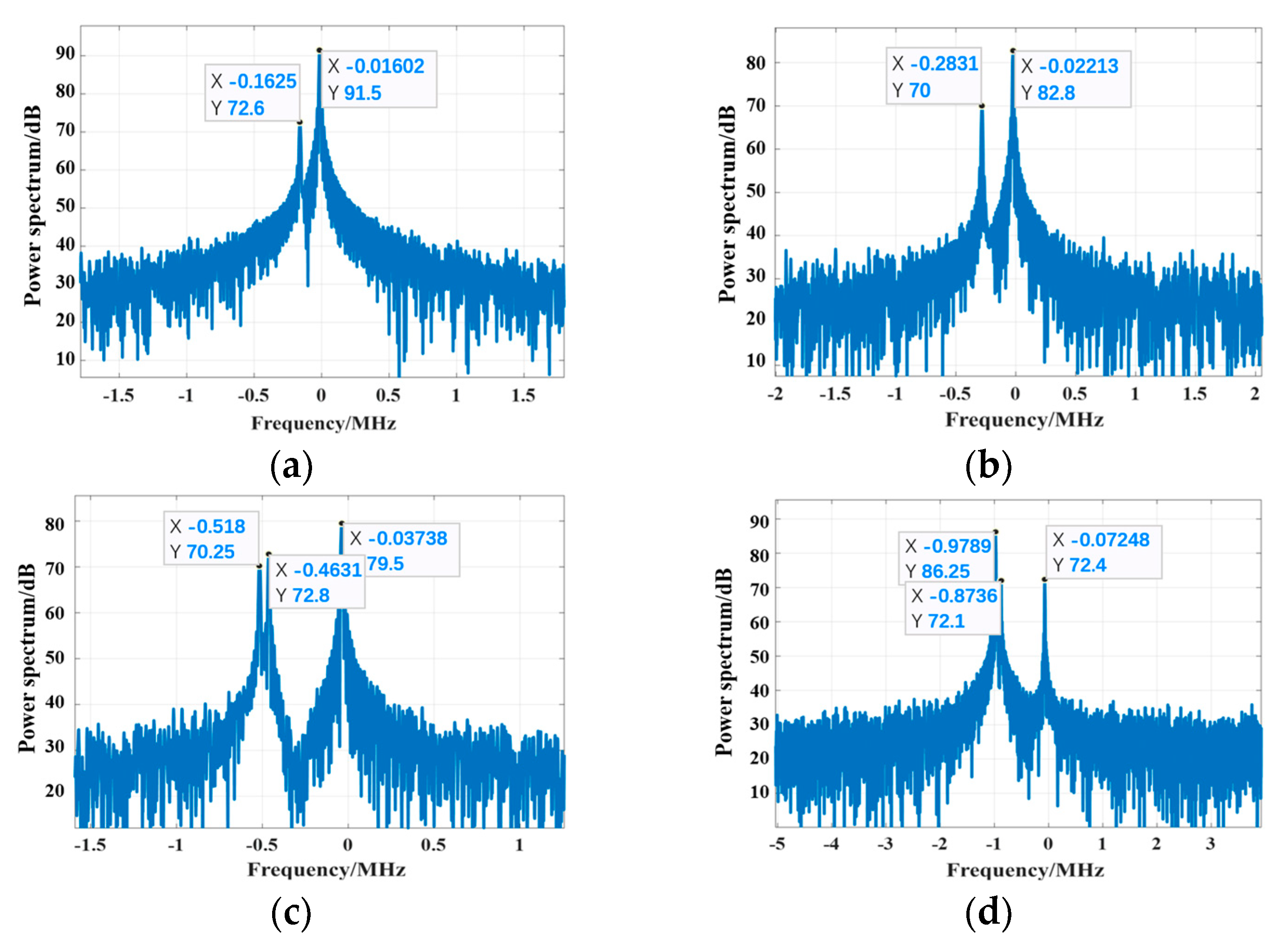
It can be observed from
Figure 15a,b that the carrier frequencies are 3.3 GHz and 5.8 GHz, respectively, for which the velocity corresponding to the maximum I-D frequency coupled in the echo signal approximates 21.7 Mach. Furthermore, the secondary energy absorption effect of the PSh imposed on the echo signal lowers the maximum peak energy from 91.5 dB to 82.8 dB. As the carrier frequency increases to 9.5 GHz, the incident depth increases, penetrating through the PSh in some areas (the wave is reflected on the vehicle surface), and the I-D frequency component coupled in the echo signal increases from two to three. An increase in the number of Doppler peaks means an increase in the number of major Doppler components of the coupling, which is due to an increase in strong reflection locations. From
Figure 15c, we observe that the maximum I-D frequency coupled in the echo signal is 0.518 MHz, which approximates the Doppler frequency corresponding to the target velocity, and the maximum peak energy is 79.5 dB. As the carrier frequency increases to 18 GHz, the EM wave component penetrating the PSh gradually increases, under which circumstance the energy of the I-D frequency corresponding to the target velocity reaches its maximum value of 86.25 dB.
At a flight altitude of 70 km:
Figure 16.
The Doppler spectrum of the echo at an altitude of 70 km: (a) fc = 3.3 GHz; (b) fc = 5.8 GHz; (c) fc = 9.5 GHz; (d) fc = 18 GHz.
Figure 16.
The Doppler spectrum of the echo at an altitude of 70 km: (a) fc = 3.3 GHz; (b) fc = 5.8 GHz; (c) fc = 9.5 GHz; (d) fc = 18 GHz.
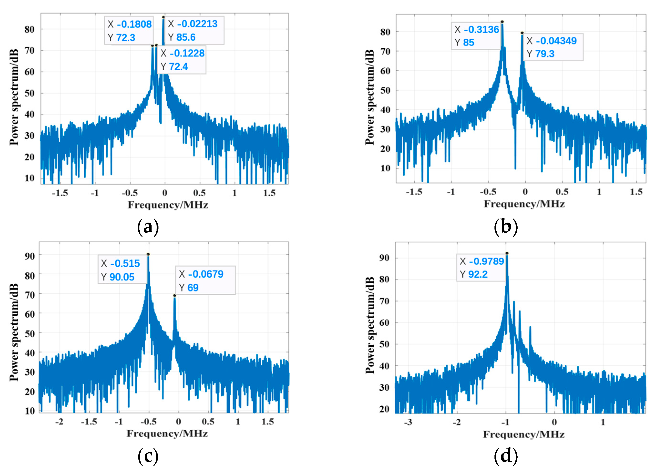
At the altitude of 70 km, the electron density is far less than that at 30 km, 50 km, and 60 km. The PSh in the vehicle’s middle and tail-end areas exert no shielding effect on the wave, for which reason the wave can penetrate the PSh and then be reflected on the vehicle surface. In the above scenario, the carrier frequency is 3.3 GHz, and the maximum I-D frequency component coupled in the echo signal is 0.1808 MHz, approximating the Doppler frequency corresponding to the target velocity. Under the circumstance of 3.3 GHz carrier frequency, despite the fact that the EM wave penetrates through the PSh, the penetration area is limited, so the secondary absorption effect of the flow field causes the minimum peak energy of the maximum I-D frequency. As the carrier frequency increases to 5.8 GHz and further to 9.5 GHz, the I-D frequency energy corresponding to the target velocity increases from 85 dB to 90 dB. As the carrier frequency increases to 18 GHz, the incident depth increases within the areas of the stagnation point and the near-stagnation point, under which circumstance the echo signal couples more frequency components. At 18 GHz carrier frequency, the wave intensity of the echo signal of the target surface increases, and the I-D frequency energy corresponding to the target velocity in the echo signal increases to 92 dB, which is much higher than other I-D frequency energies.
Table 3.
The velocity corresponding to the maximum Doppler frequency.
Table 3.
The velocity corresponding to the maximum Doppler frequency.
| Maximum Velocity | fc = 3.3 GHz | fc = 5.8 GHz | fc = 9.5 GHz | fc = 18 GHz |
|---|
| H = 30 km | 16.63 Ma | 16.77 Ma | 16.68 Ma | 16.77 Ma |
| H = 50 km | 22.32 Ma | 22.8 Ma | 22.71 Ma | 22.83 Ma |
| H = 60 km | 21.72 Ma | 21.53 Ma | 24.06 Ma | 23.99 Ma |
| H = 70 km | 24.17 Ma | 23.85 Ma | 23.92 Ma | 23.99 Ma |
Combining
Figure 13,
Figure 14,
Figure 15 and
Figure 16, the simulation results are listed in the
Table 3. It can be ascertained that at relatively low flight altitude, due to the extremely strong EM shielding effect of the PSh, the EM wave is reflected outside the PSh, and the I-D frequency coupled in the echo signal is far less than the Doppler frequency corresponding to the target velocity. As the carrier frequency increases, the corresponding velocity of the I-D frequency coupled in the echo signal remains approximately unchanged. As the flight altitude continues to increase, the electron density decreases, the EM shielding effect of the PSh degrades, the incident depth increases, and the I-D frequency component coupled in the echo signal increases. It must be noted that the secondary energy absorption effect of the PSh exerted on the EM wave results in the overall downward trend of the echo signal energy. When the flight altitude increases to 60 km and 70 km, the shielding effect of the PSh sharply degrades. When the carrier frequency remains at no less than 5.8 GHz, the EM wave is capable of penetrating through the PSh and will be reflected on the target surface, and then the echo signal couples with the I-D frequency corresponding to the target velocity. As the carrier frequency increases, the energy absorption effect of the PSh exerted on the reflection wave of the target surface degrades, whereas the energy of the I-D frequency peak corresponding to the target velocity increases slowly.


