Article

Large-Scale Solar Potential Analysis in a 3D CAD Framework as a Use Case of Urban Digital Twins

by
Evgeny Shirinyan
and
Dessislava Petrova-Antonova
*
GATE Institute, Sofia University “St. Kliment Ohridski”, 1164 Sofia, Bulgaria
*
Author to whom correspondence should be addressed.
Remote Sens. 2024, 16(15), 2700; https://doi.org/10.3390/rs16152700
Submission received: 19 May 2024 / Revised: 28 June 2024 / Accepted: 20 July 2024 / Published: 23 July 2024
(This article belongs to the Section Urban Remote Sensing)

Abstract

:
Solar radiation impacts diverse aspects of city life, such as harvesting energy with PV panels, passive heating of buildings in winter, cooling the loads of air-conditioning systems in summer, and the urban microclimate. Urban digital twins and 3D city models can support solar studies in the process of urban planning and provide valuable insights for data-driven decision support. This study examines the calculation of solar incident radiation at the city scale in Sofia using remote sensing data for the large shading context in a mountainous region and 3D building data. It aims to explore the methods of geometry optimisation, limitations, and performance issues of a 3D computer-aided design (CAD) tool dedicated to small-scale solar analysis and employed at the city scale. Two cases were considered at the city and district scales, respectively. The total face count of meshes for the simulations constituted approximately 2,000,000 faces. A total of 64,379 roofs for the whole city and 4796 buildings for one district were selected. All calculations were performed in one batch and visualised in a 3D web platform. The use of a 3D CAD environment establishes a seamless process of updating 3D models and simulations, while preprocessing in Geographic Information System (GIS) ensures working with large-scale datasets. The proposed method showed a moderate computation time for both cases and could be extended to include reflected radiation and dense photogrammetric meshes in the future.

Graphical Abstract

1. Introduction

The assessment of the solar potential of building surfaces in cities has become a significant topic due to the sustainability goals accepted in many countries. Solar incident radiation serves as one of the metrics to evaluate solar access in urban planning [1,2]. Apart from local solar cadaster maps [3,4], there are several global initiatives that help to estimate the solar potential of a site: Photovoltaic Geographical Information System (PVGIS), Global Solar Atlas and the recently released Google Solar API [5,6,7]. In Bulgaria, and particularly in Sofia, solar energy production in the urban environment appears to be a rising industry as well [8,9]. In these terms, careful planning of the impact of a new building or defining appropriate locations for PV panels on roofs or façades become essential.
The solar potential of cities and 3D city models has been examined in many research papers. Various datasets and tools are employed for this type of analysis. The calculation of solar potential can be conducted at several spatial scales: regional, municipal, and local (e.g., single building). The scale and therefore the level of precision of a study require appropriate technologies and tools for data processing and simulations. Besides rooftops, façade surfaces can also be estimated for solar potential [10,11,12]. At high latitudes, building façades are characterised by solar potential comparable to that of rooftops during the transitional seasons [13,14]. Three-dimensional city models support the assessment of solar potential in the 3D space, enabling more accurate and visually clear simulations [15,16,17].
The evaluation of solar radiation plays a crucial role in different urban scenarios. For instance, it can be part of the energy modelling of buildings and outdoor microclimate studies. The photosynthetically active radiation for vegetation requires similar calculations [18]. Wind, noise pollution, and daylight studies, as well as visual analysis, can usually share common 3D models with solar potential studies [15].
The standard EN 17037:2018, Daylight in Buildings, suggests a metric of daily direct sun exposure in hours: 1.5, 3, and 4, for minimum, medium, and high levels of recommendation, respectively, for at least one habitable room [19]. Nevertheless, in the city of Sofia, besides the orientation of a building, the ratio between the height of a building and its distance from other buildings serves as the main principle regarding solar access [20]. Therefore, it is not necessary to conduct detailed calculations of solar potential using a 3D city model because all the calculations can be done with simple 2D sections. In this case, ease of use of solar calculations is essential to promote this type of 3D analysis among professionals and a wider audience. Updating solar potential and dissemination of the results should also be taken into consideration as the urban fabric changes constantly.
A recent trend in the exploration and assessment of urban processes and environment is the development of urban digital twins (UDTs), facilitating the continuous integration, processing, analysis, and visualisation of urban data. The UDT is a virtual replica of the physical city, supporting the exchange of data from the real to the virtual world and vice versa [21,22]. The new knowledge obtained from the UDT supports informed decisions in planning, implementing, and managing sustainable cities, while providing for the health and well-being of citizens.
In this study, a popular computer-aided design (CAD) tool dedicated to calculations in 3D at the scale of a neighbourhood or a building was successfully employed in the context of the city (urban scale). The obtained results were visualised in a 3D web platform for engagement of a wider audience, thus achieving one of the primary purposes of the UDT to deliver insights for the future planning of the city. The workflow of this study involves data preprocessing, shading assessment, calculating incident-radiation, and data export for advanced visualisation. The study considers the overall performance of the applied approach regarding calculation time, territory size, and geometric details. Therefore, this paper fills a gap in the research background and can serve as a technical foundation for future studies.
The remainder of the paper is structured as follows. Section 2 presents a research background on aspects of solar studies at the city scale, acquiring weather datasets, shading, sky discretisation, 3D city models for solar studies, preprocessing large territories, and software. Section 3 highlights challenges and gaps in the research background. Section 4 describes the main components of the calculation of solar potential. Section 5 explores the settings for calculating incident radiation using synthetic data; in addition, it is dedicated to simulations for two cases: the whole city of Sofia and one of its districts. Section 6 discusses the results that were acquired. Section 7 concludes the paper and offers directions for future work.

2. State-of-the-Art

Estimating solar potential at the city scale typically includes a variety of technologies, methods, and datasets, depending on the scope of the study. Freitas et al. [23] conducted a comprehensive overview and described a broad range of computational solar radiation models and concepts implemented in many software packages used today. Generally, beam radiation is calculated using the same algorithm across various solar radiation models. Diffuse radiation can be represented in two ways: (1) isotropic, when uniform radiation comes from all the sectors of the sky (e.g., Erbs et al.’s model or Koronakis’ model), or (2) anisotropic, when radiation from the sky is variable (e.g., Hay’s or Perez’s models) [24]. Several algorithms implemented in GIS applications often use one state-of-the-sky dome per calculation: clear sky or overcast sky [25,26], while other software packages are capable of simulating climate variations using historical weather data. Freitas et al. claim that many models of solar radiation adopt an approach excluding complex phenomena, e.g., reflected radiation and material properties. Zhao et al. [27] classify scales of solar calculations into three groups: “building cluster”, “city district”, and “urban”. According to the authors, methods for calculations at the city scale can be categorised as CAD-based, relying on 3D vector datasets, and GIS-based, relying on 2.5D raster data.
A systematic analysis of scientific studies about building-integrated photovoltaics (BIPV) was carried out by Saretta et al. [12]. It considered the following criteria: (1) urban scale; (2) input spatial data; (3) calculation method of estimating solar potential; (4) tool; (5) output; (6) such parameters such as shading, reflections, etc. The analysis underlined a current interest in assessing the BIPV potential of façades and the rising demand for 3D urban models with articulated roofs in 3D as a geometrical basis for the existing urban areas.
Machine learning techniques are also used in solar studies [28], especially in cases when a 3D city model is not available. In complex urban environments, according to Vartholomaios [29], machine learning models based on sky view factor (SVF) cannot completely replace analytical calculations of solar radiation. Such models perform well only on building roofs in comparison to vertical surfaces and the ground. Zhang et al. [30] proposed a data-driven model based on Deep Generative Networks (DGN). Such a DGN model can predict solar radiation on obstructed vertical surfaces. Generative Adversarial Networks (GAN) can compute the access of the sun on ground surfaces for the different seasons of the year [31].
In general, a typical workflow for a solar potential analysis based on a 3D city model includes the following steps: weather data acquisition, 3D city modelling, calculation of incident solar radiation, shading assessment, and the visualisation of results.

2.1. Weather Data for Solar Potential

In general, solar calculations start with weather data acquisition—hourly or monthly climatic variations of solar radiation. For instance, hourly weather data can be stored in the Typical Meteorological Year (TMY) format, one of the most common types of climate data. TMY datasets come from satellite data and local measurements for a long period of time, usually more than 10 years [32], and consist of various kinds of temperature, radiation, illuminance, wind characteristics etc. The most typical climate data for each month are selected from different years. Not limited to solar access studies, this type of dataset can also be used for energy and microclimate modelling.
There are several concerns about the precision of ground measurements of solar radiation because of the high requirements for the calibration and maintenance of the sensors. Therefore, the Earth’s surface solar radiation is now commonly estimated using satellite data for the reasons mentioned above [33]. In some cases, TMY data can be modified to obtain more precise values of solar radiation [13,28] according to local measurements.
TMY datasets with solar radiation in various file formats can be acquired from sources as follows: Repository of free climate data for building performance [34], EnergyPlus (24.1.0) open source software for building energy modelling [35], White Box Technologies, providing historical weather data [36], Meteonorm software (8.2.0), delivering irradiation data [37], PVGIS, provides information on solar radiation and photovoltaic system performance [5] etc. TMY datasets are often used in building energy modelling software to simulate seasonal variations more precisely.
Solar radiation can be significantly decreased due to the local terrain. Huld et al. [32] use horizon angles based on raster datasets from the Shuttle Radar Topography Mission to consider the shading from the terrain for TMY data. The same principle is used by Meteonorm [38]. Climate.OneBuilding.org, EnergyPlus, and ASHRAE data seem to exclude the terrain shading. Typically, weather data are based on retrospective analysis and do not include a forecast. Thus, it is important to envision regular updates of TMY datasets [39].

2.2. 3D City Models of Buildings for Solar Potential Studies

There are several well-established GIS-based approaches of solar potential studies based on satellite imagery, statistics, and 2D building footprints [23]. A vast number of methods assume the usage of Digital surface models (DSM) in the raster format, obtained with various techniques (LIDAR, photogrammetry, or statistical methods), GIS, and corresponding solar models. DSM datasets, widely used in GIS, represent the physical environment in a 2.5D manner and at a fixed spatial resolution. This type of calculation became easy to adopt due to well-developed workflows. Furthermore, precalculated values for solar radiation and potential PV output can be accessed freely through services similar to PVGIS, Global Solar Atlas, etc.
3D city models, especially 3D models of buildings, are a key component of the UDT and have been widely used in solar analysis in recent years. Conducting a review of various approaches to model solar radiation in the city, Freitas et al. [23] underlined the importance of elaborating 3D models and the potential of the BIPV of a façade. Compared to 2.5D calculations, the 3D-based analysis appears to be a promising approach for further steps in environmental studies, e.g., urban building energy modelling [40] or modelling the outdoor microclimate.
3D city models can be categorised into two main groups: (1) 3D mesh models, derived from photogrammetry directly and merged into one tiled dataset, and (2) semantic 3D models, e.g., based on CityGML standard [41], often derived from point clouds or 2D geodata. The advantage of the latter is the ability to represent both spatial and semantic features of the urban fabric [42].
In the context of the urban digital twins, semantic 3D models of buildings are preferable since they can be updated more easily (each object can be modified separately) and can be reused in a wide range of cases. Various types of environmental analyses often require the geometry of a building to be subdivided into finite elements. A 3D model of a building, consisting of bounding surfaces and enriched with semantics, can provide more flexibility while preprocessing data for a simulation compared to a 3D mesh model that has its triangulation structure already fixed. Separate features of a building can be extracted and converted in a boundary representation to a mesh with variable density according to the required precision. This approach is widespread, for instance, in urban wind simulations [43], and it can be used for solar studies.
On the other hand, 3D mesh models of a city are the first step in the feature reconstruction from a point cloud acquired from a survey (photogrammetry or LIDAR), and it can be done almost automatically by software. This type of data preserves small details captured by a sensor, while semantic 3D building models are linked to the concept of Level of Detail (LOD). For example, the LOD1 has only one flat roof per building. The small details of buildings are present only at higher LODs. In this context, there have been several attempts to combine mesh geometry as input data for solar analysis with CityGML models in order to improve the accuracy of solar potential predictions [41]. In addition, according to Peronato et al. [44], the low resolution of evaluated mesh geometry strongly affects vertical surfaces (e.g., façades) in relative terms. Roofs with superstructures can be affected by the low resolution of a mesh as well. Therefore, one could apply a variable density of study points to various types of surfaces.
Mesh datasets, represented by Google high-resolution 3D Tiles, are used by Google Solar API as a basis for calculations. However, the outcome is delivered as 2D raster geodata: a digital surface model (DSM), RGB, a building mask, annual flux, and monthly flux [7].
Usually, the development of higher LODs of 3D vector models is resource-demanding. With regard to this, Biljecky et al. [45] concluded that increasing the LOD does not always have a significant impact on the precision of the shadow analysis. Moreover, it is hard to create general-purpose geometry of a 3D city model for various cases [46].

2.3. Shading Assessment Using 3D City Models

The biggest impact on energy yield from the sun in the case of a complex urban environment is the shading from surrounding static objects (buildings, roof installations, etc.) [47]. With the help of a 3D city model, shading can be clearly defined except for the weather conditions or vegetation [48]. Shadows represent the absence of the direct sun and thus exclude the first component of solar radiation, such as direct or beam radiation.
Another component of solar radiation, diffuse radiation, comes from all the parts of the sky dome. It is often obstructed by surrounding buildings, roof structures, or vegetation. The shadowing effect is modelled by applying shading masks onto the discretised sky dome [49]. The ratio between unobstructed sky and obstructed areas of the sky dome can be aggregated into the sky view factor (SVF), independent of geographic location [50]. The authors recommend using SVF as a predicting metric of solar potential on building façades. In shaded areas, the reflected component of solar radiation can produce a significant impact. Nevertheless, reflected radiation is neglected in various software packages or treated as a constant value [51]. On the other hand, calculations based on software, such as Radiance [52], consider material properties and the corresponding reflection of solar beams [53].
When dealing with hilly regions, it is important to consider the long-range shadowing effects and keep details close to buildings. For example, Bremer et al. [54] integrated coarse and fine 2.5D DEMs for long and moderate range, fine binary voxel grids for close-range vegetation consideration, and polygonal building models for close-range obstructions.
Large datasets representing distant shading can be replaced with a more lightweight solution. Gismo [55], a plugin for Rhino Grasshopper, generates a terrain-shading mask. A terrain-shading mask is a visual representation that projects the silhouette of the nearby terrain onto a sphere around a specific point, taking into consideration the effect of shading caused by the terrain. Therefore, this type of mask reduces both direct and diffuse radiation without loading large obstructing geometry. Several software applications, such as PVGIS or CitySim, propose using horizon files (a list of obstructing angles) for shading geometry [56,57].
In terms of shading context, close-range obstructions seem to be more important [47]. According to Willenborg et al. [41], the combination of detailed photogrammetric 3D mesh models and semantically enriched CityGML models has demonstrated the ability to improve the precision of solar studies.
As for other aspects, a period of a calculation (monthly, weekly, hourly), a sky model, a study object, and shading obstructions can have different resolutions [58]. Increasing the resolution of any of these components can result in more precise outcomes. In spite of that, more time for computation will be needed.
The resolution of the sky dome, representing the anisotropic distribution of irradiance, affects shading as well. The sky dome itself is usually based on the Perez all-weather sky model [59]. It is discretised to approximate continuous values acquired from the Perez model [60]. In the case of 3D ray casting algorithms, each point of a study mesh connects with all the patches of such a discretised sky dome to estimate a shading mask. Thus, the higher the number of patches of the sky dome selected, the higher the level of precision that can be achieved. There are several approaches to the discretisation of the sky dome. The Tregenza method ensures a subdivision of the dome into 145 patches [61]. The same principle allows the division of the sky dome into 577 patches when a higher level of accuracy is necessary. Nevertheless, an increase in the discretisation results in a higher calculation time for the simulation [62].

2.4. Visualisation of Solar Radiation on Building Surfaces

In GIS, solar radiation is often visualised as a matrix (raster data model) with graduated colours. The 3D city model provides visualisation of any simulations using various techniques [63,64,65]. The assessment of solar radiation in the city was classified by Biljecki et al. [15] as the case where visualisation is not important. Despite that, adding this information to the 3D context can be beneficial. Solar analysis of building surfaces is often represented in 3D as coloured grids (meshes) or as textured 3D meshes. In the case of millions of cells, 3D visualisation of such datasets on the web can be problematic due to performance issues. Bremer et al. [54] proposed a method where the textures mapped on 3D models have been used for storing the results of the calculation. An image texture of a given cell size is attached to each face of the 3D building model. A similar approach was implemented by Chaturvedi et al. [66]. In this regard, the concept of Dynamizer, introduced by Chaturvedi and Kolbe, allows the integration of dynamic properties and provides opportunities for storing and visualising solar radiation on building surfaces. Solar cadastres are a key place to visualise and disseminate solar analytics using 2D maps. However, solar cadastres in 3D also exist. For instance, textured 3D models can be found in the solar cadastre of Helsinki and Bremen [67,68]. Therefore, the results of a simulation can enrich a 3D model of a building. Besides this, 3D vector cells can also be used for visualisation purposes.

2.5. Software Technologies and Tools

Various software technologies and tools can be applied in solar potential studies at various scales. For instance, the Weather Research and Forecasting Model (WRF) enables the estimation of solar potential at the global and regional scales [69]. Traditional GIS tools usually perform calculations of solar radiation on 2.5D raster datasets [23]. Calculation of solar potential in 3D is often represented by plugins for CAD and BIM [70], or various standalone programs. In MATLAB, the concept of “hyperpoints” ensures calculations in 3D for a city or a neighbourhood [10,71]. Besides, solar potential can be calculated using urban building energy modelling (UBEM) applications [40]. Several workflows are based on PostGIS, and extensions for PostgreSQL also exist [72,73].
Several comprehensive studies have been conducted in recent years that compare different tools for calculating solar potential. Jakica [74] compared almost 200 tools to about 70 features and their integration in around 50 3D, CAD/CAM, and BIM applications.
GIS-based software packages such as GRASS GIS, SAGA GIS, or ArcGIS possess well-developed workflows for conducting solar studies at the regional scale or at the city scale [23]. Despite that, GIS applications provide no opportunity to differentiate spatially the resolution of raster data within one study and thus reduce the time of calculation. Furthermore, TMY data cannot be loaded as input for solar studies in GIS applications easily: each change in the settings of a calculation leads to a separate calculation process. The digital surface model (DSM) is still a limited basis for estimating the solar potential of façade surfaces. For example, ArcGIS Solar Analyst [26] and other similar applications do not consider reflected radiation. Therefore, applications capable of working with 3D vector models can be more suitable for façade studies.
Jakubiec and Reinhart [53] consider popular GIS tools for calculating solar radiation and compare them with radiance-based DAYSIM software that uses 3D models. DAYSIM takes into account physically accurate reflections from an urban context and rooftop temperature. The research claims that using a detailed raytracing simulation at the scale of the city (the side of the scene was around 8 km) is feasible and produces reliable results.
According to Giannelli et al. [75], the GIS-based approach is suitable for large-scale preliminary studies. For more accurate studies, one can suggest Ladybug Tools or CitySim. However, acquiring some basic knowledge of CityGML might be beneficial in this case, although both software tools allow the import of other 3D vector formats. On the other hand, this is not the case for SimStadt [76], which works exclusively with CityGML data but has the fastest simulation time.
A comparison of tools to model incident solar radiation (Wh/m2) on building façades of a theoretical neighbourhood of 100 × 100 m was conducted by Thebault et al. [77]. A wide range of tools included Ladybug tools, Honeybee, CitySim, Cadsol, and ENVI-met. The study showed small variations of solar radiation on horizontal unshaded surfaces. At the same time, the distribution of radiation on façade surfaces can vary significantly (up to 40%) due to different methods of evaluating sun positions, type of diffuse model, or exclusion of the reflection component. As for the reliability of results, estimating solar potential on rooftops seems to be more predictable. Using this logic, façade studies are more reliable in the case of standalone prominent buildings, where the effect of shading or reflected radiation from the surroundings is less significant.
Regarding performance, processing large territories remains a challenging task for any type of software. GIS provides a good starting point for heavy calculations of large datasets, but CAD, BIM, or other 3D applications are usually not well-suited for such tasks. For instance, according to the documentation of SimStadt, to reduce the volume of data to process, dividing a large 3D model into rectangular tiles is needed. This concept has been used in various studies [44,66,72]. Square tile sizes over 300 m in length are sufficient to calculate solar radiation, including shading and inter-reflections, with 1% uncertainty for medium-density districts. In high-density districts like Manhattan, New York, a minimum tile size length of 500 m is required [78]. Once the district size exceeds about one thousand buildings, SimStadt is likely to crash or slow down due to memory-management issues. To process large volumes of point clouds, the study by Vo et al. [79] introduced the concept of a “point beam” that performs a per-point analysis to keep all details of input data. This concept attempts to overcome the tiling approach, which may not include significant obstructing geometry in the calculation.
Another point is related to geometric details compared to the overall size of an analysed site and details compared to this size. In CAD applications, details under 1 m and large coordinates at the same time can cause longer calculation time or even errors in the analysis [80]. This occurs due to the limitation of 15 significant digits. In this case, it seems rational to reduce details in 2D footprints before extrusion [81], rather than trying to remove 3D features from solid geometry [82].
To address the rise of computational demand in the case of 3D high-resolution datasets, distributed computing is often used [79]. This technology can significantly reduce computation time up to ~ 100,000 points per second. Several studies have shown that PostgreSQL 3D calculations can be computationally expensive [72]. In this case, if the raytracing process is implemented for each hour separately, calculation time can take days for several million study points on a dedicated server machine (~2 points per second) [73]. To reduce the time for computation, triangulated building surfaces can be stored in a bounding volume octree index structure [16].

3. Challenges and Gaps

In general, it is important to provide a sufficient level of usability when evaluating solar potential at the city scale. Furthermore, there is a need to integrate large geodata and typical CAD/BIM workflows when working with 3D city models. Autodesk Forma [83] and other similar cloud-based applications connect BIM with 3D city models almost seamlessly and provide capabilities of analysis, but on a project level only.
3D CAD and BIM tools are widespread among architects and urban planners. Rhino and Ladybug Tools are used mainly at the scale of the neighbourhood or building, and parametric studies use lightweight 3D models [12,84,85,86,87]. In relation to this, one could say that the Ladybug Tools plugin as a CAD-based tool is under-represented in city-scale studies.
This study attempts to provide an in-depth insight into the applicability of the tools dedicated to performing small-scale analysis and simulations, like Ladybug, to evaluate solar potential and to explore limitations, performance issues, and the potential of those tools at the city scale. As for the type of geometry, LOD1 3D vector models are considered. The UDT concept and its functionalities are related to the solar potential analysis to show how real-world urban scenarios fit into the UDT’s lifecycle. Figure 1 presents the main UDT functionalities. The data functionality is at the core, providing synchronisation between the physical and digital cities, based on the two-way connectivity between them. The physical city use is usually equipped with sensors and devices providing real-time data for urban processes and environment, like air pollution, noise, traffic, etc. The reactive functionality analyses this data to obtain insights that can be stored back through the data functionality for further visualisation. The “What-If” functionality allows various simulations to be performed in the digital twin to explore the impact of potential interventions and make decisions about which to apply to the physical city. The predictive functionality can be employed for planning, which is the case for the current study. In the context of solar potential analysis, this can be used for planning buildings appropriate for the installation of PV panels, taking measures for cooling buildings exposed to sunlight for more than 8 h, or assessing the microclimatic comfort of outdoor spaces.
In general, this paper explores the extent to which tools dedicated to small-scale studies can support 3D analysis within the wider context of UDT, as shown in Figure 1.
To define recommendations for solar potential analysis using CAD-based calculations at the city scale, the following specific questions are considered:
  • What kind of geometric preprocessing of terrain data and building footprints is required at the city scale before further analysis in a 3D CAD system?
  • Which components of the calculation of solar potential using the CAD-based raytracing method have the most significant impact on computation performance, leading to the improvement of data pipelines for UDTs?
  • How can the results of the calculations be visualised on the web at the city scale?

4. Materials and Methods

This section presents the methodology for processing geospatial data and calculating solar radiation at the city scale.

4.1. Study Area and Data

The territory of Sofia Municipality is characterised by a temperate–continental climate. It is located in the climatic region “Sofia Field”, surrounded by mountains. The most prominent mountain, Vitosha, in the south, causes various climatic effects [88]. The sunshine in Sofia lasts an average of 2065 h annually, with the maximum occurring in July at 302 h and the minimum in December at 55 h. The total solar radiation (direct and diffuse) in Sofia is 121.4 kcal/cm2 (1412 kWh/m2) annually, with peak values occurring in July (with an average monthly value of 17.3 kcal/cm2, or 201.2 kWh/m2) and the lowest values in December (averaging 3.3 kcal/cm2, or 38.4 kWh/m2 per month).
The first case study includes the territory of the city of Sofia with an urbanised area covering around 210 km2. It takes approximately 15% of the total area of the Sofia Municipality, where urbanisation is very low. In the city of Sofia, most buildings have up to 4 floors, with high-rise buildings (15–35 floors) accounting for 0.16% of the total number. Due to its diverse geometry, infrastructure, and environment, the district of Lozenets in Sofia has been selected as a second case study. The district is characterised by low-rise and mid-rise residential buildings, and is densely built-up in the north. At the same time, there are regions to the south where intensive construction takes place.
The datasets for the calculations include 2D vector building footprints in *.shp format for the entire city, terrain as a raster file in *.tif format with a 1-m resolution, and a point cloud sourced from a photogrammetric survey for the Lozenets district. These data are provided by Sofiaplan, a municipal enterprise responsible for the spatial and strategic planning of Sofia Municipality.

4.2. General Workflow

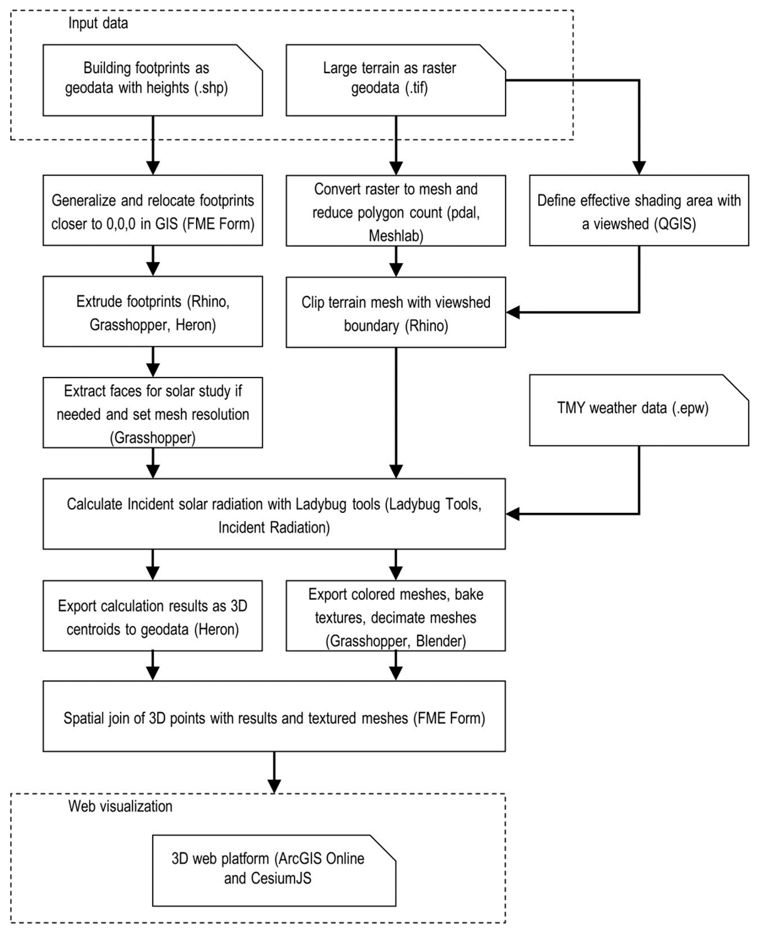
The overall workflow for preprocessing geodata, solar studies, and the integration with a 3D web platform are shown in Figure 2.
First, the simplification of geometry was conducted. The building footprints were relocated closer to the origin of the co-ordinate system and simplified. Then, the footprints were extruded using Grasshopper and stored in Rhino as solid geometries. Finally, each building solid was converted to a mesh. The raster dataset of the terrain was converted to a 3D mesh and decimated in Meshlab. Several viewsheds were generated using sample points to remove unnecessary terrain parts, representing potential high-rise buildings in the main city area. In terms of the calculation of solar radiation, two cases were evaluated, including rooftops at the city scale and all building surfaces at the district scale. For visualisation and dissemination purposes, the resulting meshes were transferred to a 3D web platform for geospatial visualisation. The results for the rooftops were directly converted to 3D polygons in the Esri shapefile format. The radiation values on the 3D surfaces of the buildings at the district scale were transformed into textures using the 3D rendering software Blender and exported to a 3D web platform.

4.3. Preprocess Geodata and Generation of 3D LOD1 Buildings

Building footprints were imported into a PostGIS database as 2D objects and related tables. Then the footprints were extruded into polyhedral surfaces. The import of extruded polyhedral surfaces via the Heron plugin [89] into Rhino led to incorrect orientation of face normals. Thus, the extrusion was performed in the 3D CAD system using Heron’s capabilities. Before importing into Rhino, the 2D geometry of the footprints had to be processed. According to Rhino specifications, calculations are expected to be accurate to 15 digits of precision in a range from ±1020 to ±10−20. This limitation can be found in all modern CAD applications.
First, the initial footprints were relocated closer to the origin of the co-ordinate system to minimise the range of values. The decimal precision of co-ordinates can be reduced as well, if needed. The simplification process appears to be more effective using 2D footprints compared to the processing of 3D geometry. A similar method was explored by Naserentin et al. [81]. Footprints that are below a certain area threshold (e.g., less than 20 m2) were excluded from the process.
To remove details from the footprints, a widely used method of a minimum oriented bounding box (MOBB) [90] was applied. If the ratio of a footprint area to an area of a corresponding MOBB is higher than 0.9, then this feature can be replaced with an oriented rectangular shape. This step removes small details and keeps the overall character of a shape at the same time. Other features can be generalised or simplified using algorithms like Douglas-Peucker [91] with selected distance parameter (e.g., 1 m). Sub-meter edges can cause very small faces, and this often leads to errors in Ladybug Tools while working with large models [92].
The building footprints were extruded using heights from point clouds and other sources in Rhino using the Heron plugin. This step ensures the generation of topologically correct LOD1 solids. If building parts were present, they were merged into one watertight geometry using a grouping field previously defined in the dataset with 2D footprints. Thus, the geometry of buildings was modelled in LOD1.3, a variation of LOD1, according to Biljecki et al. [93]. In this case, a footprint could be subdivided if differences in height were significant. The obtained objects were tessellated in Rhino with a 3-m edge size. Similar procedures were performed for the dataset of the Lozenets district, where most buildings were modelled in LOD1.3.

4.4. Effective Shading Terrain Surface and 3D Terrain Generation

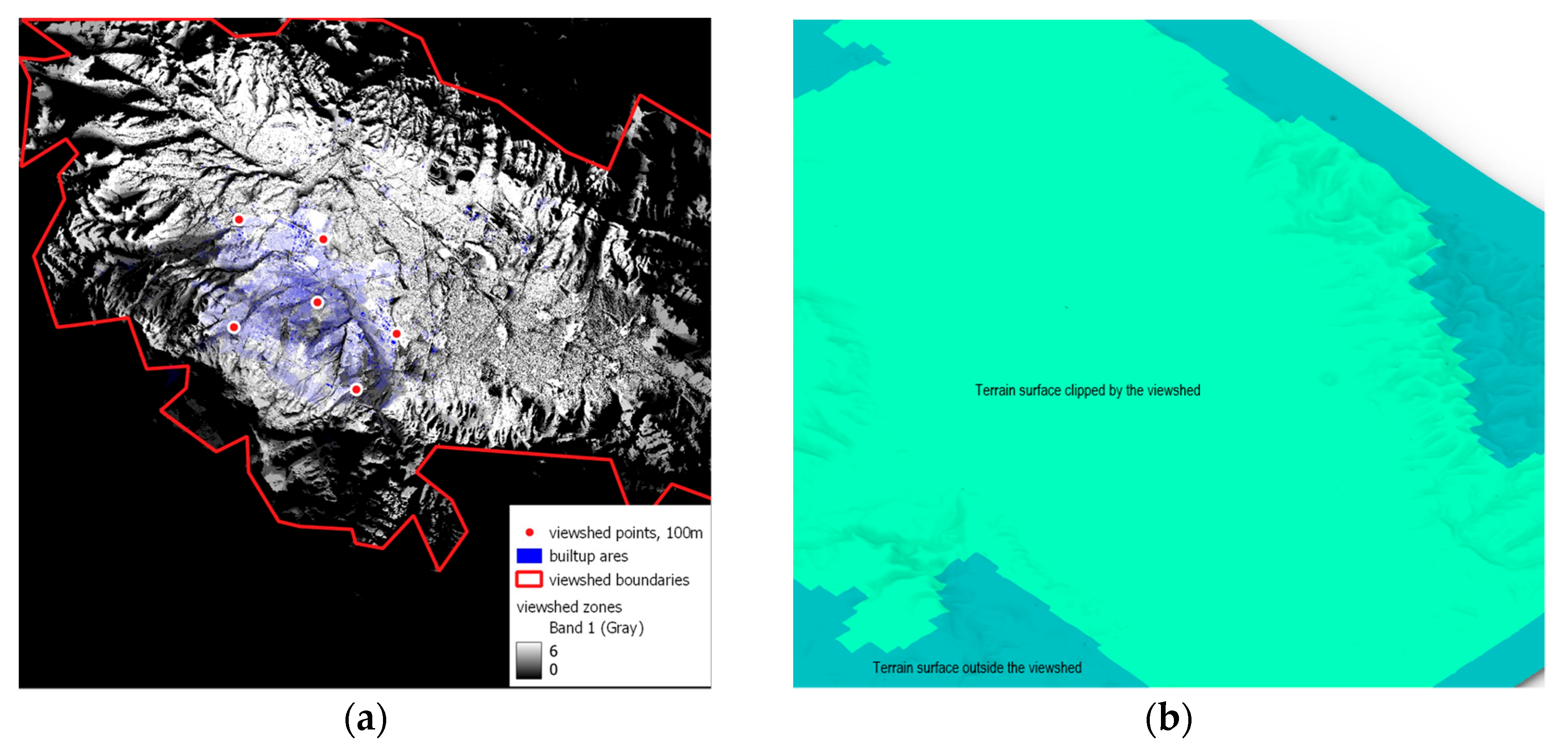
First, a coarse digital surface model (DSM), obtained from ArcGIS WorldDEM service, was utilised to define an effective shading surface for the city of Sofia. Figure 3a shows this step which was conducted using the viewshed algorithm in QGIS [94]. Observer points were positioned in the corners and in the centre of the main city area at a height of 100 m above the ground. Thus, such possible high-rise buildings, which could be shaded by the mountains, were used to define a shading surface of the terrain. Viewshed areas from the observer points were calculated with a radius of 35 km, and the boundary of an effective shading surface was obtained. Then, the DSM model was converted to a point cloud with a C++ library PDAL, triangulated, and decimated using variable cell density in Meshlab. Finally, Figure 3b demonstrates the mesh clipped with the viewshed boundary in Rhino.
Two preliminary calculations of solar incident radiation were performed with default settings and compared using the sensitivity analysis approach. The comparison of the two cases showed no difference in solar radiation of the vertical surface, and this clipped terrain surface could be used for subsequent steps.

4.5. Weather Data Acquisition

In Sofia, the highest value of solar radiation can be expected in June, when the sun is at its highest position and the amount of air for it to penetrate is at its lowest. Despite that, in reality, the highest solar radiation occurs in July, when the air is more transparent, compared to in June [95]. According to Ivanova [96], the horizontal solar radiation has exceeded the values specified in the local codes by an average of 25% annually over the last 10–15 years, reaching up to 33% in July.
TMY datasets from various sources had to be compared and adapted according to local measurements [97]. Nevertheless, several concerns about the precision of such measurements exist [31].
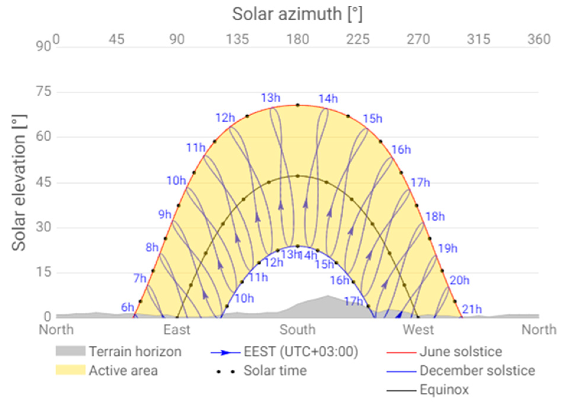
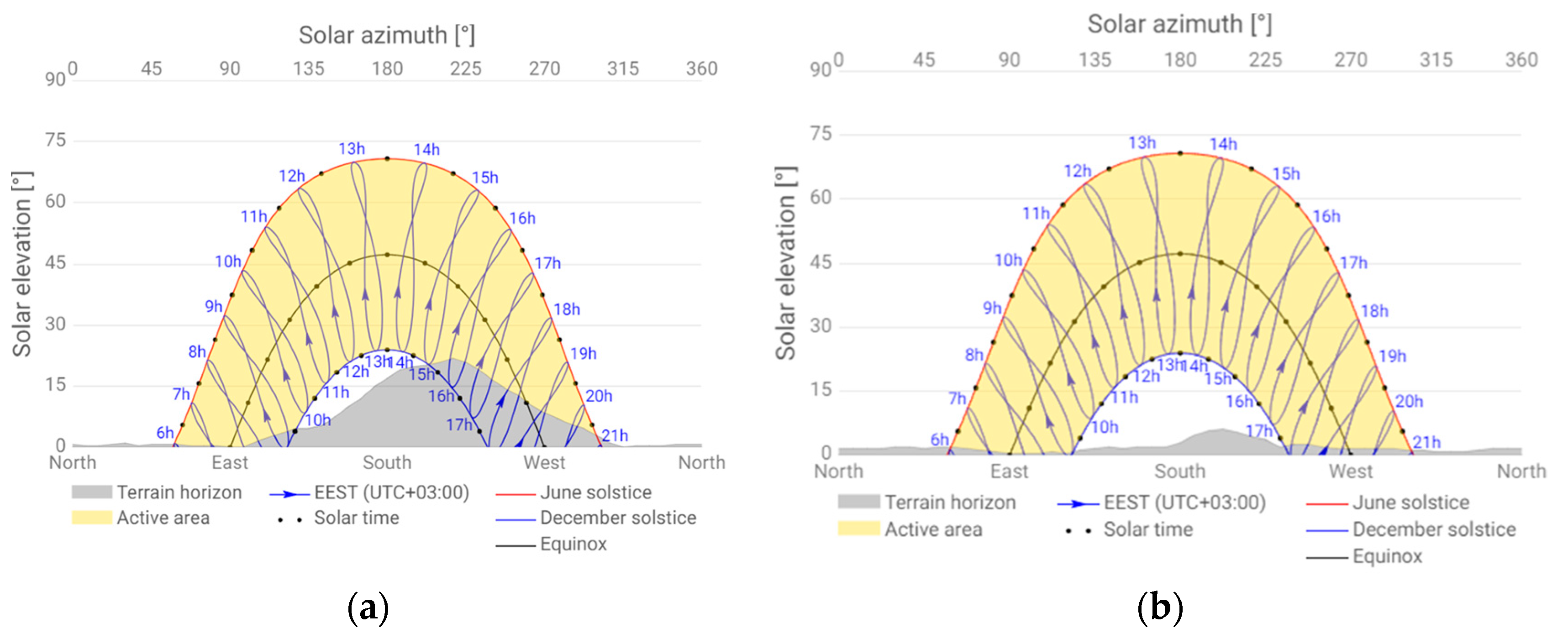
If one takes the centre of Sofia (42.694296°, 23.321056°), the visualisation of a shading mask by Global Solar Atlas [98] represents the potential impact of the surrounding terrain [Figure 4]. The Vitosha mountain blocks a certain amount of solar radiation from the south in autumn and winter. Other sectors are less significant.
In the case of PVGIS datasets, solar data can be acquired for any specific site in the TMY format. However, there is no clear understanding of whether PVGIS datasets exclude terrain shading or not: both datasets, downloaded from the website, show identical values. Therefore, a dataset in the EnergyPlus Weather Format (EPW) from Climate.OneBuilding.org was selected. The EPW file contained 8760 hourly values of a year for each meteorological parameter. This file format stores TMY data, and it is often used for solar studies in applications such as Ladybug Tools.

4.6. Calculating Solar Radiation

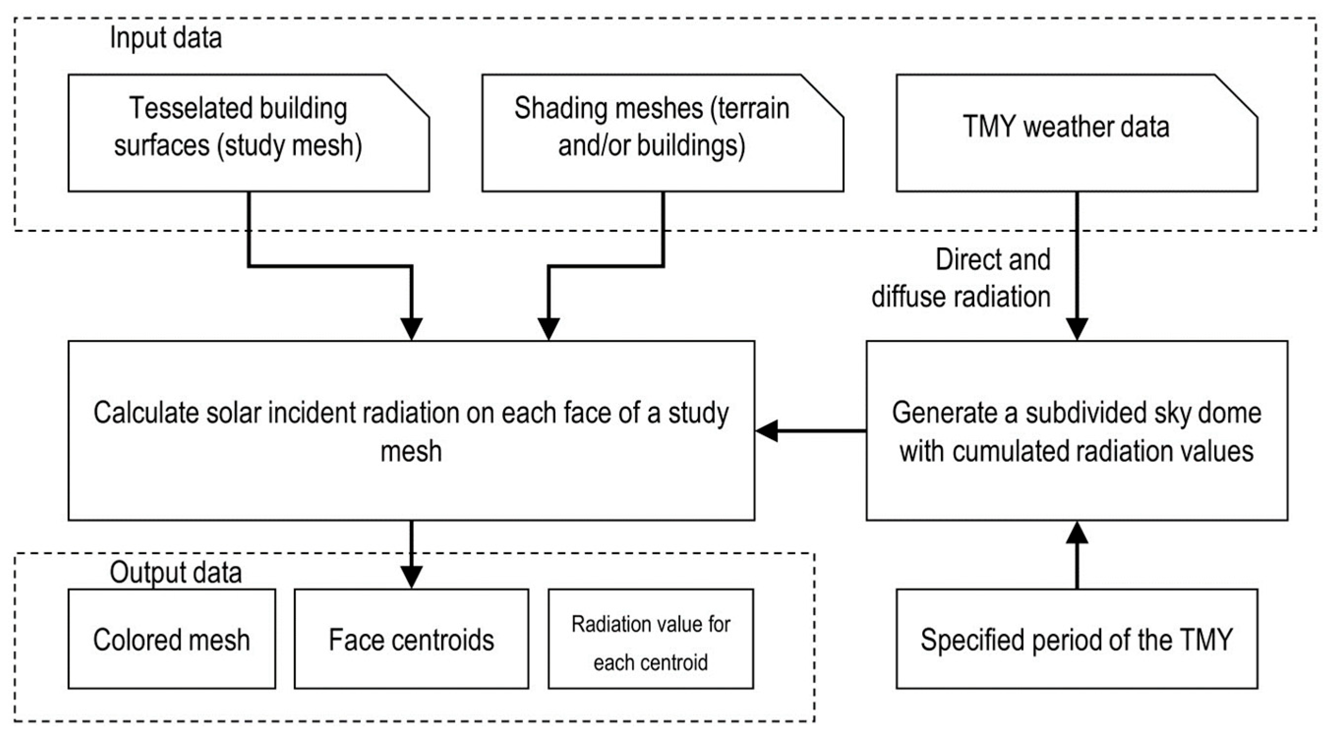
This section discusses a simplified calculation of solar radiation compared to the Radiance-based Honeybee algorithms, also included in the Ladybug Tools suite (v. 1.6.0). The overall process of the calculation in LBT is represented in Figure 5. First, TMY weather data is imported as the Ladybug Import EPW component. Location, direct normal radiation, and diffuse horizontal radiation feed the generation of the Cumulative Sky Matrix component for a specified period of the year. The output of this component is used to calculate cumulative radiation coming from each face (patch) of the subdivided sky dome. The next component computes incident radiation, also known as irradiation, for study objects, considering shading geometry and self-shading. The resulting data from the incident radiation component can be exported as coloured meshes and various tabular data.

4.6.1. Generation of the Cumulative Sky Matrix

Creating the cumulative sky matrix is essential before conducting incident radiation analysis with Rhino geometry or generating a radiation rose [99]. The component uses TMY data: location, direct normal irradiation (in LBT—direct normal radiation), and diffuse horizontal irradiation (in LBT—diffuse horizontal radiation). This component runs the Radiance’s gendaymtx function to calculate the total radiation for each patch of the sky for a specified period of the year (by default all the 8760 h of a year are selected). A similar procedure is used by the software SOLARES [100]. The LB cumulative sky matrix component takes weather data as input (e.g., preprocessed from an *.epw weather file) and produces a matrix of sky segment radiance values for a selected period (e.g., yearly, monthly, or daily) using the Perez all-weather sky model. The average cloud cover for each hour of the sky is accounted for as well. The resolution of the cumulative sky matrix affects precision and calculation time. The number of intersections between a face and shading geometry is associated with the number of faces in the study mesh and the number of patches in a selected sky subdivision. By default, Tregenza sky (145 patches) is used for both hemispheres, which leads to 290 intersections for each study face. When the option “high density” sky is activated, the Reinhart subdivision (577 patches) generates 1154 intersections for both hemispheres for each study face, which is almost four times higher compared to the Tregenza sky.
Using a precomputed sky matrix that accumulates solar radiation significantly reduces the time needed for calculations. As a result, there is almost no difference between studying a full year of 8760 h or just a single day once the matrix is computed. At the same time, it is unknown when and for how long a face is shaded [75].

4.6.2. Ladybug Incident Radiation

Calculation of incident radiation [101] on mesh faces is performed using the output from the LB Cumulative Sky Matrix and the intersection matrix between a face and shading geometry. Input geometry and shading geometry are tessellated with predominantly quadrilateral faces by the component with a desirable size of cell. However, one can tessellate geometry beforehand to avoid additional calculation tasks in the Grasshopper workflow. For each centroid of the mesh face, the sky mask is constructed. This mask blocks radiation from the sky dome and the resulting value of radiation is computed. The incident radiation component does not include any reflections of solar energy. Ground-reflected radiation is represented by an emissive “ground hemisphere” associated with the LB cumulative sky matrix component. The default value for ground reflectance is set to 0.2 (20% of the intensity of the sky hemisphere), and it is taken into consideration only when the physical ground surface is absent. The ray tracing is conducted for a full sphere around each point (a centroid of a mesh face). Nevertheless, geometry representing the ground surface will block reflected radiation from the virtual ground.
Ladybug incident radiation represents the simplified approach in calculating solar radiation without the reflected component compared to Honeybee, which is based on the validated radiance engine [13]. For instance, Thebault et al. [77] showed that differences in solar radiation values between Ladybug Incident Radiation and Honeybee occur mainly in shaded areas and on façades oriented to the north. At the same time, the results for a flat, unobstructed surface are very similar.

4.6.3. Transferring Results to a 3D Web Platform

The output from LB Incident Radiation is represented by a coloured mesh, with each face having a vertex colour assigned. The resulting mesh is not divided into the initial buildings if processed in a regular way. The exact value for each face is exported as a separate list of values. In the case of roofs, results can be converted to geodata easily. For this purpose, a plugin, Heron, was utilised. Within GIS, the initial footprints are enriched with simulation results using the spatial join. Then, separate grid cells are categorised by radiation values and dissolved into larger 3D polygons, so the range of values and the number of objects to be visualised in a 3D web platform are reduced significantly.
Vertical surfaces, e.g., façades, are harder to export to a geospatial format. In addition, it is hard to visualise a few millions 3D faces in a regular web browser. Vertex colours of a large mesh cannot be shown on platforms like ArcGIS Online (February, 2024) or CesiumJS (1.119). Another issue is related to the data structure of the output from LBT: all the resulting 3D meshes are merged by the incident radiation component into one single mesh.
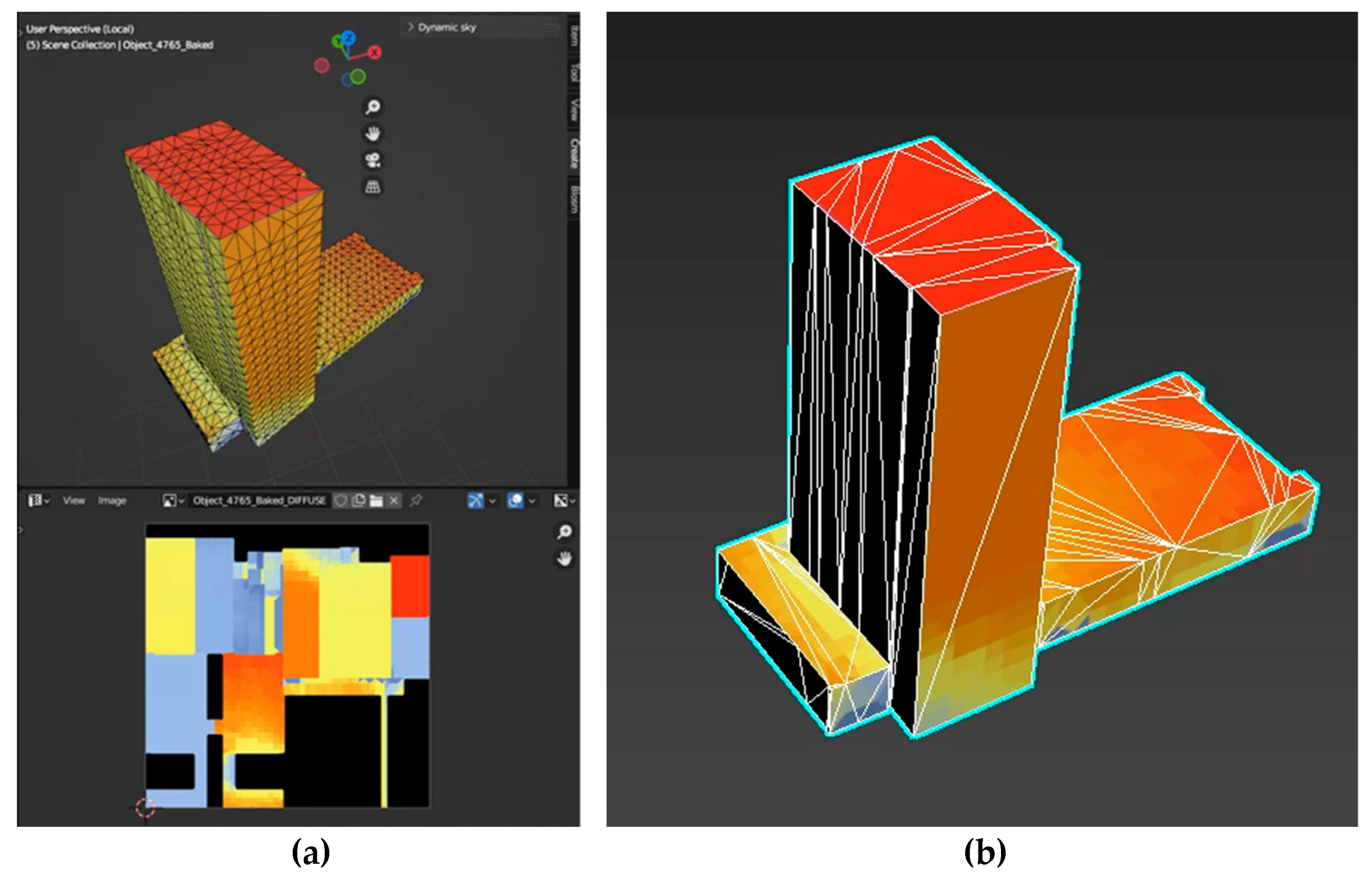
Transference of vertex colours to textures from the initial 3D model to the simplified 3D model was conducted, as illustrated in Figure 6. This kind of process is also called texture baking. Thus, the textures mapped onto 3D models store the visual results of the calculation.
FME Form imports textured meshes of the 3D building and converts them to a geodatabase in ArcGIS. Then these data are exported to a 3D web platform. Thus, two methods of visualising calculation results on the web are envisioned.

5. Results

This section presents the experiments conducted and the results obtained. The first experiment estimated the impact of large distant shading objects (e.g., mountains) on calculation results. The second study, based on synthetic data, evaluated the optimal settings for the resolution of meshes while using the incident radiation component in Ladybug Tools. Case 1 explored a process of preparing building footprints and calculating the incident radiation for the city of Sofia. Only the rooftops of 64,379 residential buildings were included in the analysis. Acquired simulation results were exported as separate grid cells with radiation values to a 3D web platform. Case 2 demonstrates the usage of the incident radiation component for all surfaces of 4796 buildings in the district of Lozenets, Sofia. The results of the simulation were transferred as 3D textured geometry for visualisation on the web. The radiation results were assessed through sensitivity analysis rather than by using absolute values. This approach allows for a more nuanced understanding of how changes in input variables impact the outcomes, providing a clearer picture of the factors influencing the radiation levels.
The study was conducted using the following computer configuration: i7-7700, RAM 32 GB DDR4 2133 MHz, GTX GeForce 1050 Ti, and SSD.

5.1. Impact of Large Distant Shading Objects

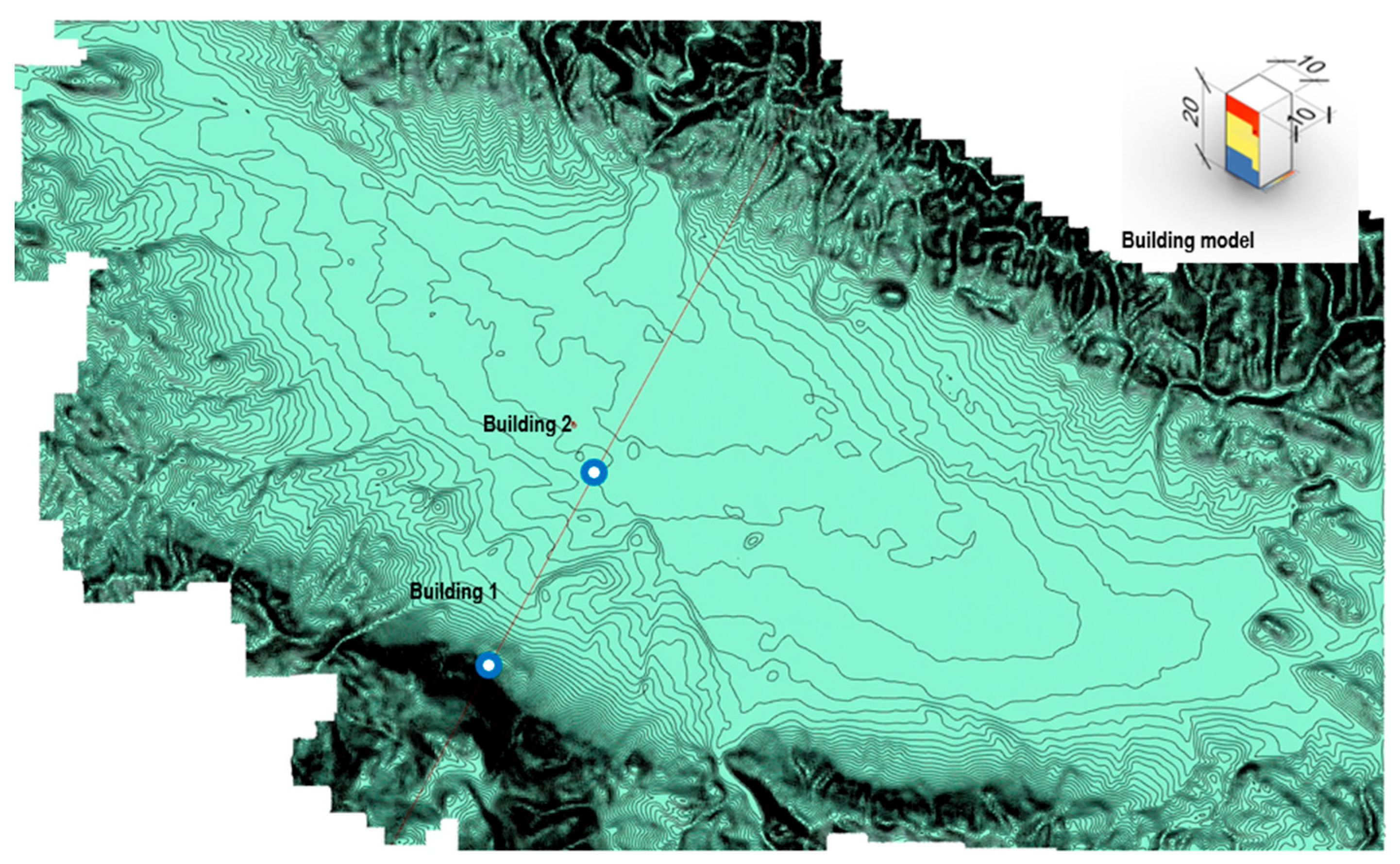
This step assesses the impact of distant shading objects on the calculation results. All the calculations were conducted using ground geometry. Figure 7 shows two cases examined for two sample buildings: the impact of a distant mountain on horizontal planes (flat roofs) and a vertical plane (a wall). The selected vertical planes for the evaluation are facing southwest. The Reinhart subdivision was selected for a more detailed assessment of shading.
A real terrain surface was selected, where the Vitosha mountain obstructed radiation coming from the sky dome. Most areas of Sofia are exposed to direct sunlight. Figure 8 represents how the terrain obstructed the path of the sun for Building 1 and Building 2.
As shown in Table 1, there was no significant impact (2.5% of unobstructed radiation) from distant mountains on the horizontal faces of Building 1, which was located near the mountain. The impact of the mountains on the horizontal faces of Building 2 was almost negligible (99.9%). Table 2 demonstrates the higher rates of reduction of incident radiation on vertical faces.
In addition, the assessment of a shading context, similar to the functions of Global Solar Atlas or PVGIS, can be conducted using the sky mask component. Sky mask, based on the selected sky matrix, can be visualised as a fish-eye projection in Grasshopper after the incident radiation is calculated and an intersection matrix is generated. This can be useful to evaluate the relationship between shading objects and the sky matrix of a selected point. However, visualisation of the Reinhart-based sky mask was only achieved due to several inconsistencies of the component.

5.2. Synthetic Buildings

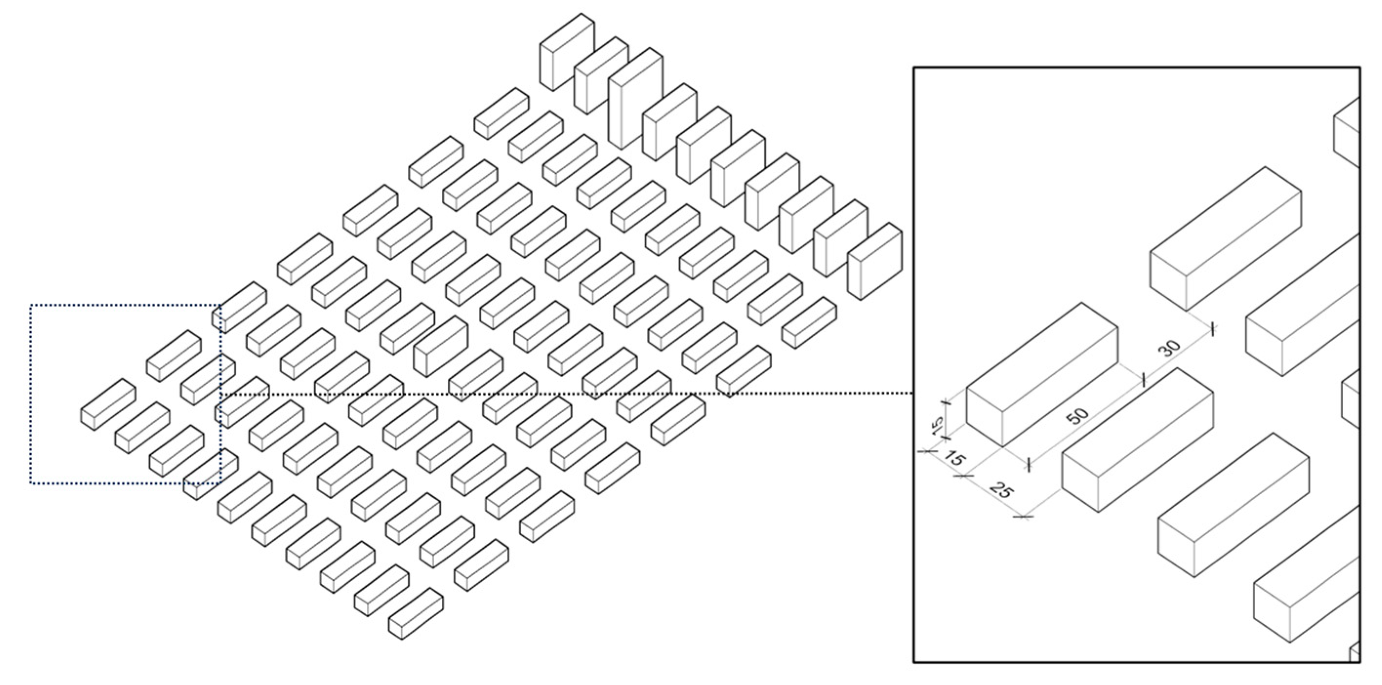
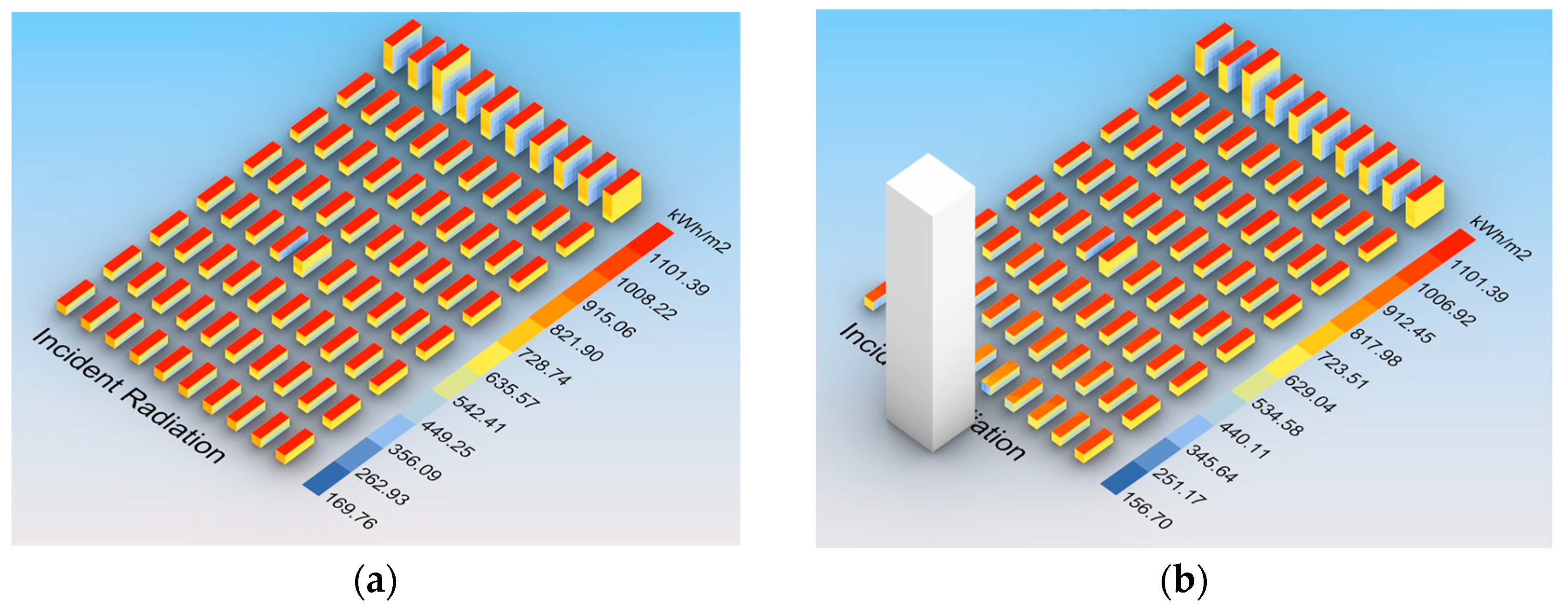
This essential step demonstrates the relationship between the tessellation of a study mesh, the sky dome subdivision, and the resulting time of calculation. The impact on calculation time of the face count of a study mesh, the face count of a context mesh, and the resolution of the sky dome was explored. The calculation was conducted using a set of 3D buildings representing an urban area (Figure 9). The variations in height help to assess local shading effects (e.g., higher buildings to the north will block diffuse radiation).
The absence of ground surface allows reflected radiation to contribute to the overall values. Figure 10 demonstrates two cases of calculated incident radiation, without shading geometry and with shading geometry, respectively.
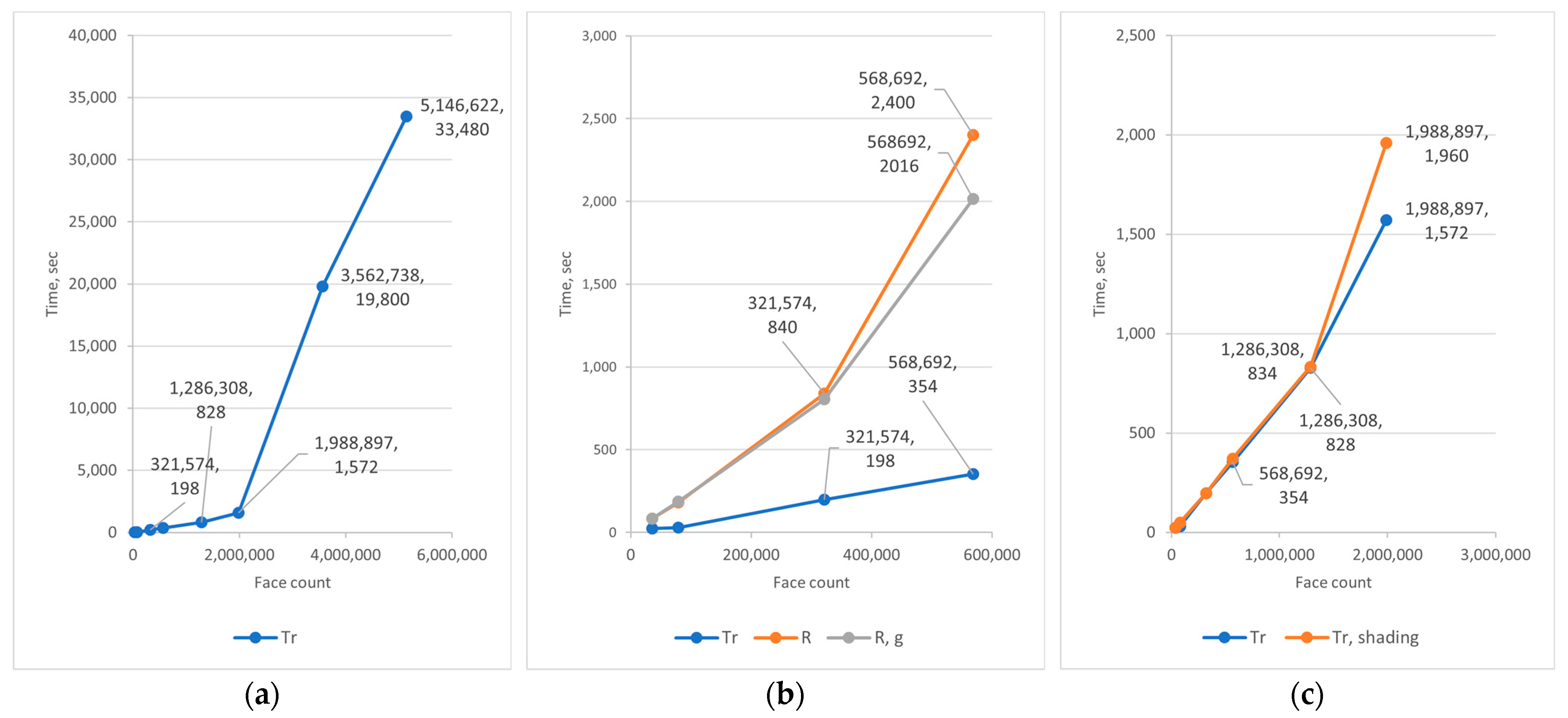
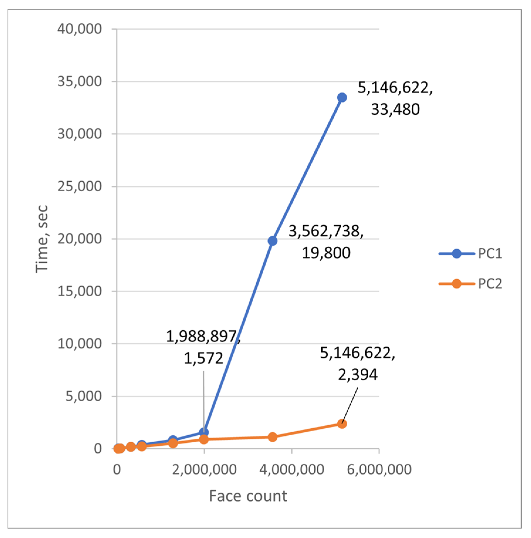
Table 3 shows various scenarios for the calculations: the Tregenza subdivision of the sky dome (Tr), the Tregenza subdivision of the sky dome including shading geometry with 446,984 faces (Tr, shading), the Reinhart subdivision of the sky dome (R), and the Reinhart subdivision of the sky dome when every box is calculated separately (R, graft). To ensure the stability of calculation, a study with 5,146,622 faces used a scaled model with a 1 m size of grid instead of 0.25 m. Freezing of the computer is shown as “-”.
Figure 11a demonstrates a linear character of the time/face count ratio. After 2 million faces, the time cost begins to increase exponentially, and the application starts to freeze frequently. Figure 11b shows a slight decrease in time for the Reinhart subdivision with grafting. Despite that, separating a set of objects into chunks using the grafting method in Grasshopper does not provide a stable solution when the RAM is full, and Rhino starts to use the pagefile as virtual memory. This can be resolved by increasing the amount of RAM or by performing calculations in parallel using the Hops add-on.
Shading geometry can be added separately in the LB incident radiation component. Figure 11c shows that there is no significant impact from a shading mesh with 446,984 faces on calculation time, but slight differences arise on the higher number of faces. This is possible due to the relatively low number of patches in the Tregenza sky model. In addition, shading geometry does not reflect any radiation and just blocks the rays between an evaluated point and a sky patch.

5.3. Case 1. City Scale

In this case, the calculation of the solar potential for the entire city of Sofia, including the terrain of the surrounding mountains, was considered.
All the datasets were acquired from Sofiaplan in the *.shp format, in coordinate reference system BGS2005/CCS2005 (EPSG:7801). The building heights were calculated based on the number of floors above ground. The height of the floor in a building was determined according to the functional usage.
The goal of this case was to evaluate the calculated point count and the possible scale of the shading surfaces. However, the assessment of the whole city surface (as we could imagine in the case of ArcGIS) could not be achieved without processing in batches. The calculation of flat surfaces is not so useful in 3D and can be done using 2.5D raster datasets as well.
First, the optimised surface of the terrain was imported into Rhino. Then the relocated footprints were loaded via Grasshopper, extruded, and stored as a single-mesh object within Rhino. Thus, the number of operations involving large data processing in Grasshopper were reduced.
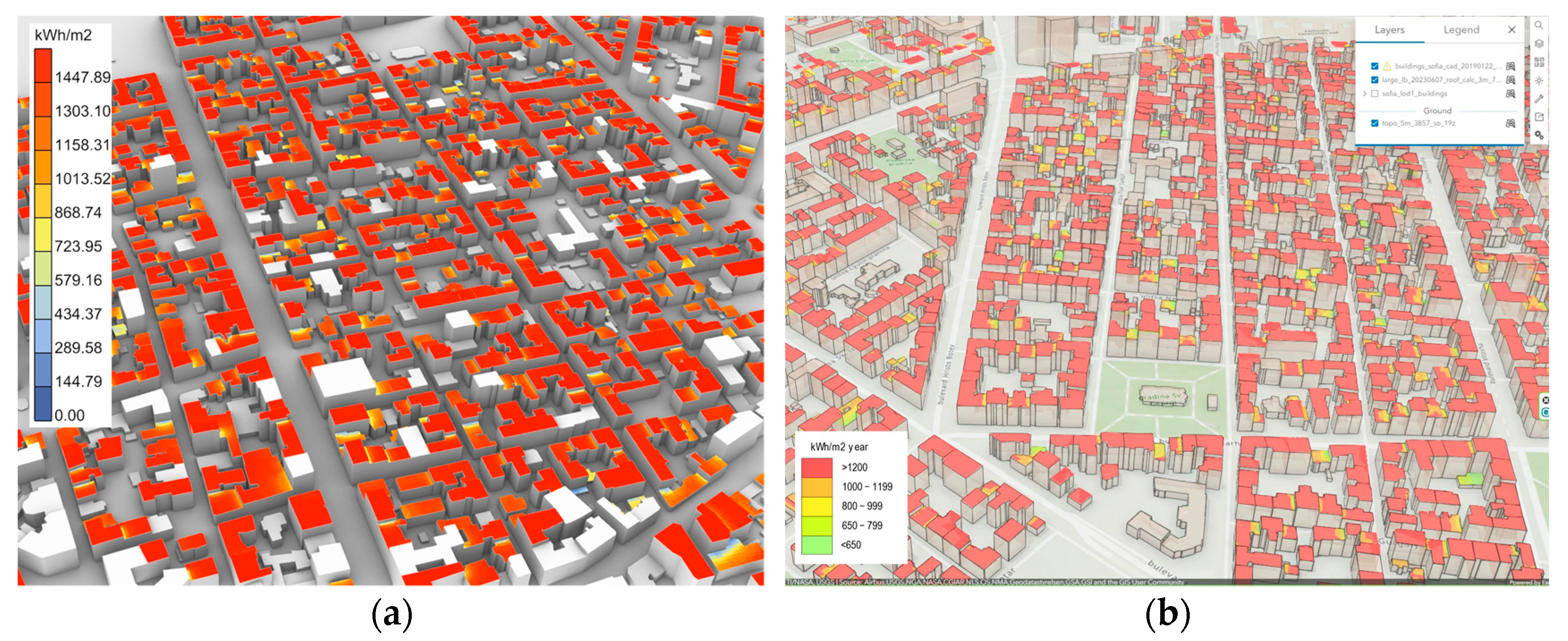
To reduce time-consuming calculations, only 64,379 rooftops of residential buildings were selected for the analysis. Footprints with areas below 20 m2 were excluded. The total size of the dataset resulted in 17,233 by 18,327 m. All the selected building contours were simplified and relocated closer to 0.0 using SQL queries in PostGIS. The resulting contours were imported into Grasshopper and extruded. The conversion of boundary representation objects into meshes with a 3-m edge length resulted in 1,909,499 faces. The calculation took 1926 s. The option for a 2-m edge length was also explored and resulted in 3,698,725 faces. The calculation took 12,240 s, which demonstrates a significant increase in time. Therefore, one can recommend 2,000,000 faces as the optimal mesh size for calculation using a hardware configuration similar to PC1.
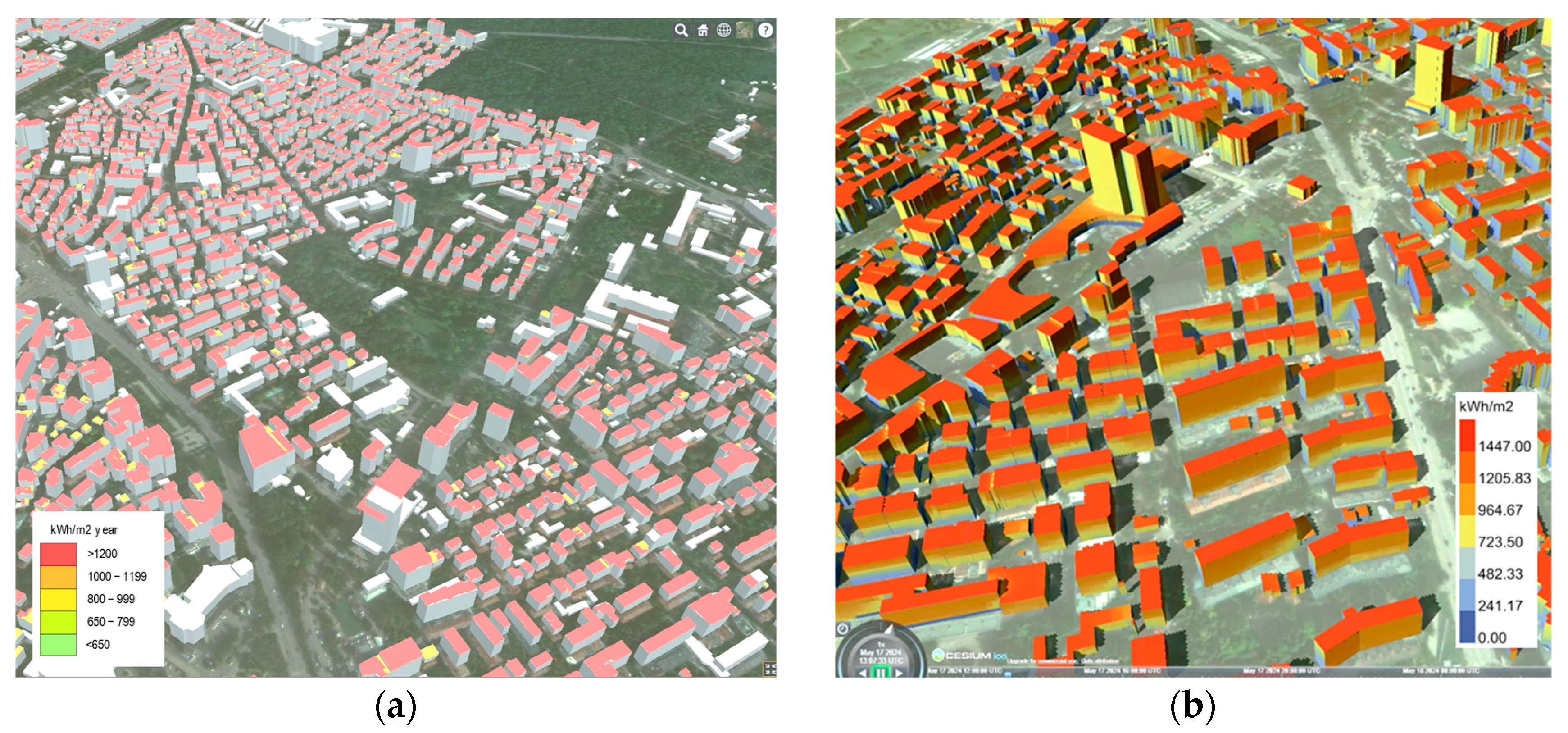
The resulting cells were exported to Esri Shapefile format. To reduce the number of polygons, the radiation values were dissolved using a unique identifier and uploaded to ArcGIS Online. Figure 12 demonstrates the visualisation of the results in Rhino and in ArcGIS Online.

5.4. Case 2. District Scale

To calculate all the building surfaces, the district Lozenets was selected. The size of the district is 5813 by 2365 m. Footprints from the cadastral map were subdivided into parts according to height differences. The initial DSM was clustered into groups by height value using the Segment Mean Shift algorithm in ArcGIS Pro.
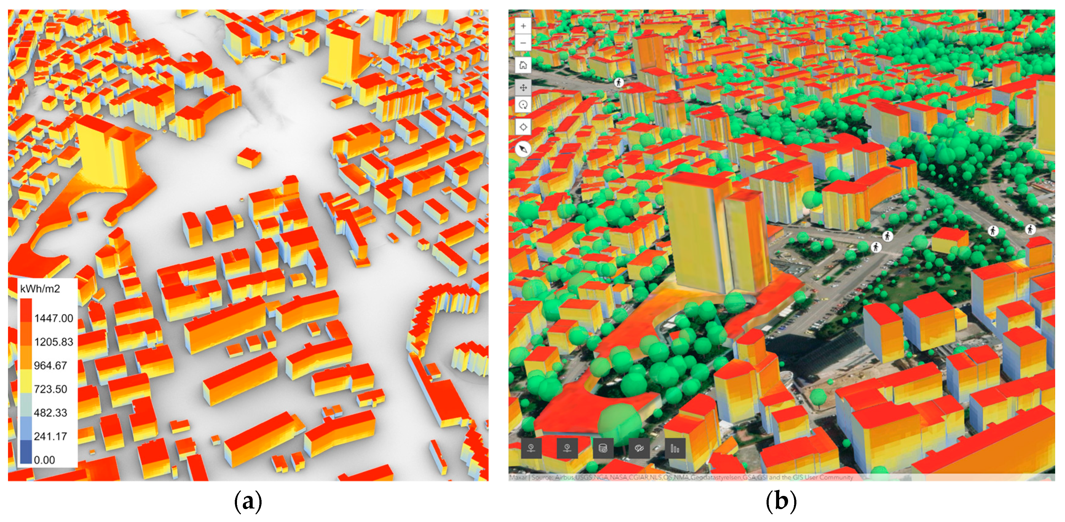
Following the procedure described in Section 4.3, the building footprints of the district were optimised and imported into Grasshopper. The surrounding terrain was imported as well. Settings for the calculation were used as follows: the Tregenza sky subdivision, grid size 3 m, and 1,008,585 faces for analysis. This step was executed in 684 s. To obtain the solar potential for each building separately, the process of grafting in Grasshopper was applied to 4796 buildings. This calculation took 15,480 s.
To transfer such a large mesh with coloured vertices to a 3D web platform, a method proposed by Bremer et al. was used. Figure 13 shows a visualisation of solar potential in Rhino and ArcGIS Online. Figure 14 illustrates a similar visualisation in CesiumJS using the same datasets.

6. Discussion

In general, the findings indicate that the method based on raytracing algorithms and CAD software can be applicable to the assessment of solar potential at the city scale. The experiments conducted with synthetic data confirm the ratio between a count of faces and calculation time.

6.1. Use Cases

Case 1 shows the possibility of including large-scale shading in calculations. Evaluating solar potential for numerous study meshes across a city is feasible without dividing a 3D city model into batches. The overall face count should be less than 2,000,000 points for stable calculation on a regular computer with 32 GB of RAM. To keep calculations stable, façades can be assessed separately. Exporting to a 3D web platform using the Esri shapefile format with 3D geometry seems to be a robust and simple approach.
Case 2 explores the evaluation of the solar potential of a compact area (for example, a city district) in 3D. If radiation values are needed for each building separately, simulation takes 15,480 s. To avoid grafting in Grasshopper, one can generate mesh as geodata before calculations and join further results using a unique identifier. For identification purposes, co-ordinates of a centroid and a normal vector can be used. Table 4 shows similar ratio values for three experiments across all the scales. The smallest ratio value belongs to Case 1, where the size of shading meshes was quite large.
As for more powerful hardware configurations, one can use RAM with a higher capacity. Figure 15 shows a comparison between the initial configuration and the more advanced one (i7-13700F, RAM 128 GB 4000MHz, RTX GeForce 4070, SSD—PC2) for the synthetic buildings. The calculation of solar radiation for 5,000,000 points does not exceed 40 min on PC2, while the same count of points takes more than 9 h.
Traditional GIS tools show comparable performance. For example, the area radiation tool in ArcGIS computes 78,000,000 cells (2731 km2) for 14,400 s (24 h), and the ratio face count/s is around 902. The process of calculation is very stable with large volumes of data. The use of GPUs can be essential for such calculations. The Raster Solar Radiation tool, which is GPU-based, computes 78,000,000 cells for 900 s, so the ratio face count/s is above 86,000.
In terms of geometry, the method mentioned suggests a certain flexibility in generating meshes. Study meshes or shading geometry can be represented as non-watertight meshes, while watertight geometry is usually required in CFD applications. In the case of analysis at the city scale, it is recommended to keep the edge length and the face area above 1 m and 1 m2, respectively. Co-ordinate values have to be reduced as well.
The task of visualising in 3D, especially on the web, is still quite challenging. One can export incident radiation values and grid cells in separate streams. Then each cell can be linked with a corresponding value using co-ordinates and a normal vector as a joining index. Point clouds are also a potential playground for the representation of results. Transferring simulation results from coloured meshes to textured 3D models can be a viable option when the meshes are highly detailed.

6.2. Limitations

In this study, no reflected radiation and material properties were considered. Vegetation was disregarded as well, but it can be added easily as a shading geometry. Adaptive meshing for roofs and façades was not implemented. The considered method is suitable for cumulative radiation values. However, exact hours of direct sunlight cannot be identified if the duration of solar access is required. While live updates are not part of the method in the case of large models, the software itself is specifically designed to give dynamic feedback for small 3D datasets. TMY weather data should be compared to local measurements and modified if needed [39]. Real-time measurements of solar radiation could be a helpful resource for the retrospective analysis of historical weather data and an impact of the microclimate on various activities in a city. In addition, other raytracing engines can be explored.
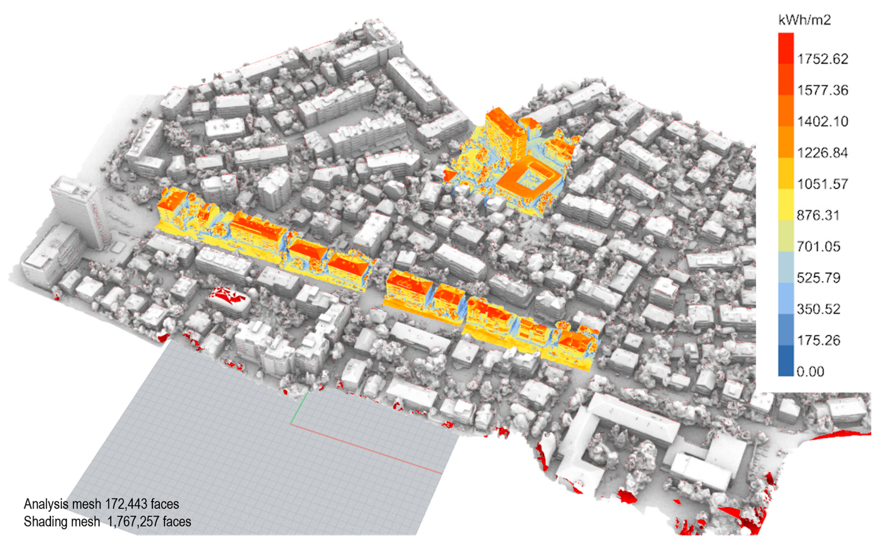
As for the usage of more realistic geometric representation in the calculation, a sample area of the Lozenets district, based on dense photogrammetric meshes, was evaluated, as shown in Figure 16. The study area was divided into analysed meshes and a shading mesh. The results of this experiment proved the main findings of the paper in terms of geometric requirements, settings for the calculation, and processing time.

6.3. Challenges and Gaps

This section discusses the main research findings according to the challenges and gaps defined in Section 3.
First, the kind of geometric preprocessing of terrain data and building footprints was investigated by considering further analysis in a 3D CAD environment. For this purpose, all the geometric data have to be relocated closer to the origin of a CAD environment. If model units are meters, geometric details under 1 m (for example, edge length) should be avoided in the case of large models. In the case of mountains, distant shading geometry can be defined using the viewshed approach. Shading geometry can be subdivided using the minimal count of faces. For study meshes, one can extract faces that are needed only for the assessment.
In terms of performance and precision, the sky dome subdivision and study mesh resolution are crucial parameters for the calculation of solar potential using the CAD-based raytracing method, like Ladybug incident radiation. All the calculations were conducted in one batch. A shading mesh can be quite large. Surrounding mountains can reduce solar potential in the case of vertical faces (e.g., building walls) by up to 20%. In the case of the Ladybug incident radiation component, a number of 2,000,000 faces is feasible for a standard computer configuration with 32 GB RAM. The ratio of face count per second averaged 1200.
Finally, the visualisation of results on the web at the city scale was explored with the aim of delivering valuable insights for decision-making in UDTs. There are several ways to visualise the simulation results of solar potential on the web at the city scale. The first method assumes dissolving mesh faces with the same values into larger faces. This approach ensures straightforward access to the radiation values within the context of the UDT web interface. The second method proposes the transfer of radiation results to the textures of a 3D model (so-called “texture baking”), so that initial study meshes can be replaced with 3D models with a low number of faces.

7. Conclusions and Outlook

The existing research background considered CAD-based calculations mainly at the scale of the neighbourhood or the district. Evaluating solar potential at the city scale in one batch seems to be impractical because it can be done with convenient GIS tools with higher stability or using the tiling approach. However, this study explores the possibilities and limitations of the CAD-based approach in the calculation of solar incident radiation at the city scale. In accordance with most requirements, the method proposes to generalise and relocate all geometry data closer to the origin in a CAD environment. To reduce terrain shading surfaces, the viewshed calculation for a study is utilised in GIS. A synthetic dataset and two cases were considered to define the optimal face count of study meshes for the simulations. As a result, a number of 2,000,000 faces can be used as a reference point for a regular computer with 32 GB of RAM for future studies. The key findings show almost no difference in study scale, whether dealing with a district or a whole city. The ratio of face count per second reached approximately 1200–1400 faces. A total of 64,379 roofs for the whole city and 4796 buildings for one district were evaluated. Large distant objects, such as mountains, can reduce radiation values on vertical walls by up to 20%. All calculations were performed in one step. Therefore, the use of a 3D CAD environment could establish a seamless process of updating 3D models and simulations for UDTs, while preprocessing of geometry in GIS ensured the ability to work with large-scale datasets. Finally, the results were visualised in a 3D web platform using 3D polygons and textured building models. Two options for visualisations were used: proprietary software and an open-source solution.
In future work, usage of the CityGML data model for buildings is anticipated to store simulation results. Calculations can be extended to include reflected radiation, material properties, vegetation, and dense photogrammetric meshes. To ensure dynamic feedback between solar studies and a UDT, a method of updating simulation results should include the effective partitioning of a 3D city model.

Author Contributions

Conceptualisation, E.S. and D.P.-A.; methodology, E.S. and D.P; software, E.S.; validation, E.S.; formal analysis, E.S.; investigation, E.S.; resources, E.S.; data curation, E.S.; writing—original draft preparation, E.S.; writing—review and editing, E.S. and D.P.-A.; visualisation, E.S.; supervision, D.P.-A.; project administration, D.P.-A.; funding acquisition, D.P.-A. All authors have read and agreed to the published version of the manuscript.

Funding

This research was supported by the GATE project, funded by the H2020 WIDESPREAD-2018–2020 TEAMING Phase 2 programme, under grant agreement no. 857155 and FLEdge projects, funded by the Driving Urban Transitions (DUT) Partnership programme, under agreement no. KP-06-D002/5.

Data Availability Statement

The data presented in this study are available on request from the corresponding author. The data are not publicly available due to usage of 3D party data.

Acknowledgments

The authors gratefully acknowledge Stoyanka M. Ivanova (UACEG, Sofia) for the insightful discussion of methods to calculate solar radiation.

Conflicts of Interest

The authors declare no conflicts of interest.

References

  1. Czachura, A.; Kanters, J.; Gentile, N.; Wall, M. Solar Performance Metrics in Urban Planning: A Review and Taxonomy. Buildings 2022, 12, 393. [Google Scholar] [CrossRef]
  2. Hasan, J.; Horvat, M. Spatial Parameters and Methodological Approaches in Solar Potential Assessment-State-of-the-Art. Renew. Sustain. Energy Rev. 2023, 188, 113857. [Google Scholar] [CrossRef]
  3. Suitability of Roofs for the Use of Solar Energy. Available online: https://www.geocat.ch/geonetwork/srv/eng/catalog.search#/metadata/b614de5c-2f12-4355-b2c9-7aef2c363ad6 (accessed on 1 February 2024).
  4. City of Vienna. Vienna Environmental Good. Available online: https://www.wien.gv.at/umweltgut/public/grafik.aspx?ThemePage=9 (accessed on 1 February 2024).
  5. JRC Photovoltaic Geographical Information System (PVGIS)-European Commission. Available online: https://re.jrc.ec.europa.eu/pvg_tools/en/ (accessed on 1 February 2024).
  6. Global Solar Atlas. Available online: https://globalsolaratlas.info/map?c=42.694296,23.586273,11&s=42.688997,23.345947&m=site (accessed on 1 February 2024).
  7. Google Maps Platform. Solar API Concepts. Available online: https://developers.google.com/maps/documentation/solar/concepts (accessed on 1 February 2024).
  8. Startira Kandidatstvaneto Na Domakinstvata Za Finansirane Na Fotovoltaichni Sistemi [Household Applications for Photovoltaic Systems Financing Launched]. Available online: https://me.government.bg/themes/startira-kandidatstvaneto-na-domakinstvata-za-finansirane-na-fotovoltaichni-sistemi-2454-1639.html (accessed on 1 February 2024).
  9. Solar Cities–Project Cities powered by sun. Available online: https://solarcities.bg/ (accessed on 1 February 2024).
  10. Catita, C.; Redweik, P.; Pereira, J.; Brito, M.C. Extending Solar Potential Analysis in Buildings to Vertical Facades. Comp. Geosci. 2014, 66, 1–12. [Google Scholar] [CrossRef]
  11. Jaugsch, F.; Löwner, M.-O. Estimation of Solar Energy on Vertical 3d Building Walls on City Quarter Scale. Int. Arch. Photogramm. Remote Sens. Spat. Inf. Sci. 2016, XLII-2-W2, 135–143. [Google Scholar] [CrossRef]
  12. Saretta, E.; Bonomo, P.; Frontini, F. A Calculation Method for the BIPV Potential of Swiss Façades at LOD2.5 in Urban Areas: A Case from Ticino Region. Sol. Energy 2020, 195, 150–165. [Google Scholar] [CrossRef]
  13. Manni, M.; Nocente, A.; Kong, G.; Skeie, K.; Fan, H.; Lobaccaro, G. Solar Energy Digitalization at High Latitudes: A Model Chain Combining Solar Irradiation Models, a LiDAR Scanner, and High-Detail 3D Building Model. Front. Energy Res. 2022, 10, 1082092. [Google Scholar] [CrossRef]
  14. Formolli, M.; Kleiven, T.; Lobaccaro, G. Solar Accessibility at the Neighborhood Scale: A Multi-Domain Analysis to Assess the Impact of Urban Densification in Nordic Built Environments. Sol. Energy Adv. 2022, 2, 100023. [Google Scholar] [CrossRef]
  15. Biljecki, F.; Stoter, J.; Ledoux, H.; Zlatanova, S.; Çöltekin, A. Applications of 3D City Models: State of the Art Review. ISPRS Int. J. Geo-Inf. 2015, 4, 2842–2889. [Google Scholar] [CrossRef]
  16. Willenborg, B.; Sindram, M.; Kolbe, T.H. Applications of 3D City Models for a Better Understanding of the Built Environment. In Trends in Spatial Analysis and Modelling: Decision-Support and Planning Strategies; Behnisch, M., Meinel, G., Eds.; Springer International Publishing: Cham, Switzerland, 2018; pp. 167–191. ISBN 978-3-319-52522-8. [Google Scholar]
  17. Kolečanský, Š.; Hofierka, J.; Bogľarský, J.; Šupinský, J. Comparing 2D and 3D Solar Radiation Modeling in Urban Areas. Energies 2021, 14, 8364. [Google Scholar] [CrossRef]
  18. Tan, P.Y.; Ismail, M.R.B. The Effects of Urban Forms on Photosynthetically Active Radiation and Urban Greenery in a Compact City. Urban Ecosyst. 2015, 18, 937–961. [Google Scholar] [CrossRef]
  19. Standards, E. BS EN 17037:2018+A1:2021 Daylight in Buildings. Available online: https://www.en-standard.eu/bs-en-17037-2018-a1-2021-daylight-in-buildings/ (accessed on 27 February 2024).
  20. Naredba № 7 ot 22 Dekemvri 2003 g. za Pravila i Normativi za Ustroystvo na Otdelnite Vidove Teritorii i Ustroystveni zoni [Ordinance no. 7 of 22 December 2003 on Rules and Codes for the Development of Certain Types of Territories and Development zones]. Available online: https://lex.bg/laws/ldoc/2135476546 (accessed on 1 February 2024).
  21. Singh, M.; Fuenmayor, E.; Hinchy, E.P.; Qiao, Y.; Murray, N.; Devine, D. Digital Twin: Origin to Future. Appl. Syst. Innov. 2021, 4, 36. [Google Scholar] [CrossRef]
  22. VanDerHorn, E.; Mahadevan, S. Digital Twin: Generalization, Characterization and Implementation. Decis. Support Syst. 2021, 145, 113524. [Google Scholar] [CrossRef]
  23. Freitas, S.; Catita, C.; Redweik, P.; Brito, M.C. Modelling Solar Potential in the Urban Environment: State-of-the-Art Review. Renew. Sustain. Energy Rev. 2015, 41, 915–931. [Google Scholar] [CrossRef]
  24. Yang, D. Solar Radiation on Inclined Surfaces: Corrections and Benchmarks. Sol. Energy 2016, 136, 288–302. [Google Scholar] [CrossRef]
  25. Šúri, M.; Hofierka, J. A New GIS-Based Solar Radiation Model and Its Application to Photovoltaic Assessments. Trans. GIS 2004, 8, 175–190. [Google Scholar] [CrossRef]
  26. Fu, P.; Rich, P. Design and Implementation of the Solar Analyst: An ArcView Extension for Modeling Solar Radiation at Landscape Scales. In Proceedings of the IX Annual ESRI User Conference, San Diego, CA, USA, 26–30 July 1991. [Google Scholar]
  27. Zhao, H.; Yang, R.J.; Liu, C.; Sun, C. Solar Building Envelope Potential in Urban Environments: A State-of-the-Art Review of Assessment Methods and Framework. Build. Environ. 2023, 244, 110831. [Google Scholar] [CrossRef]
  28. Ni, P.; Yan, Z.; Yue, Y.; Xian, L.; Lei, F.; Yan, X. Simulation of Solar Radiation on Metropolitan Building Surfaces: A Novel and Flexible Research Framework. Sustain. Cities Soc. 2023, 93, 104469. [Google Scholar] [CrossRef]
  29. Vartholomaios, A. A Machine Learning Approach to Modelling Solar Irradiation of Urban and Terrain 3D Models. Comput. Environ. Urban Syst. 2019, 78, 101387. [Google Scholar] [CrossRef]
  30. Zhang, Y.; Schlueter, A.; Waibel, C. SolarGAN: Synthetic Annual Solar Irradiance Time Series on Urban Building Facades via Deep Generative Networks. Energy AI 2023, 12, 100223. [Google Scholar] [CrossRef]
  31. Deep Umbra. Available online: https://www.evl.uic.edu/shadows/ (accessed on 25 February 2024).
  32. Huld, T.; Paietta, E.; Zangheri, P.; Pinedo Pascua, I. Assembling Typical Meteorological Year Data Sets for Building Energy Performance Using Reanalysis and Satellite-Based Data. Atmosphere 2018, 9, 53. [Google Scholar] [CrossRef]
  33. PVGIS Data Sources & Calculation Methods-European Commission. Available online: https://joint-research-centre.ec.europa.eu/photovoltaic-geographical-information-system-pvgis/getting-started-pvgis/pvgis-data-sources-calculation-methods_en (accessed on 1 February 2024).
  34. Climate.Onebuilding.Org. Available online: https://climate.onebuilding.org/ (accessed on 1 February 2024).
  35. EnergyPlus Weather Data. Available online: https://energyplus.net/weather (accessed on 1 February 2024).
  36. White Box Technologies. ASHRAE IWEC2 Weather Files. Available online: http://weather.whiteboxtechnologies.com/IWEC2 (accessed on 1 February 2024).
  37. Meteonorm. TMY3 (NREL & DWD). Available online: https://meteonorm.com/en/typical-meteorological-years (accessed on 1 February 2024).
  38. Meteonorm Horizon Tiles. Available online: https://meteonorm.com/en/horizon-tiles (accessed on 1 February 2024).
  39. Ivanova, S. Climate Scenario-Based Design and Construction and Regional Climate Models. In Proceedings of the VIII International Scientific Conference “Industry 4.0”, Winter Session, Borovets, Bulgaria, 6 December 2023; pp. 336–339. [Google Scholar]
  40. Johari, F.; Peronato, G.; Sadeghian, P.; Zhao, X.; Widén, J. Urban Building Energy Modeling: State of the Art and Future Prospects. Renew. Sustain. Energy Rev. 2020, 128, 109902. [Google Scholar] [CrossRef]
  41. Willenborg, B.; Pültz, M.; Kolbe, T.H. Integration of Semantic 3d City Models and 3d Mesh Models for Accuracy Improvements of Solar Potential Analyses. Int. Arch. Photogramm. Remote Sens. Spat. Inf. Sci. 2018, XLII-4/W10, 223–230. [Google Scholar] [CrossRef]
  42. Gröger, G.; Plümer, L. CityGML–Interoperable Semantic 3D City Models. ISPRS J. Photogramm. Remote Sens. 2012, 71, 12–33. [Google Scholar] [CrossRef]
  43. Pađen, I.; García-Sánchez, C.; Ledoux, H. Towards Automatic Reconstruction of 3D City Models Tailored for Urban Flow Simulations. Front. Built Environ. 2022, 8, 899332. [Google Scholar] [CrossRef]
  44. Peronato, G.; Rey, E.; Andersen, M. 3D Model Discretization in Assessing Urban Solar Potential: The Effect of Grid Spacing on Predicted Solar Irradiation. Sol. Energy 2018, 176, 334–349. [Google Scholar] [CrossRef]
  45. Biljecki, F.; Ledoux, H.; Stoter, J. Does a Finer Level of Detail of a 3D City Model Bring an Improvement for Estimating Shadows. In Advances in 3D Geoinformation; Abdul-Rahman, A., Ed.; Springer International Publishing: Cham, Switzerland, 2017; pp. 31–47. ISBN 978-3-319-25691-7. [Google Scholar]
  46. Biljecki, F.; Ledoux, H.; Stoter, J.; Vosselman, G. The Variants of an LOD of a 3D Building Model and Their Influence on Spatial Analyses. ISPRS J. Photogramm. Remote Sens. 2016, 116, 42–54. [Google Scholar] [CrossRef]
  47. Alam, N.; Coors, V.; Zlatanova, S.; Oosterom, P.J.M. Shadow Effect on Photovoltaic Potentiality Analysis Using 3D City Models. Int. Arch. Photogramm. Remote Sens. Spat. Inf. Sci. 2012, XXXIX-B8, 209–214. [Google Scholar] [CrossRef]
  48. Peronato, G.; Rastogi, P.; Rey, E.; Andersen, M. A Toolkit for Multi-Scale Mapping of the Solar Energy-Generation Potential of Buildings in Urban Environments under Uncertainty. Sol. Energy 2018, 173, 861–874. [Google Scholar] [CrossRef]
  49. Marsh, A. The Application of Shading Masks in Building Simulation. In Proceedings of the International IBPSA Conference: Building Simulation 2005, Montréal, QC, Canada, 15 August 2005; pp. 725–732. [Google Scholar]
  50. Chatzipoulka, C.; Compagnon, R.; Kaempf, J.; Nikolopoulou, M. Sky View Factor as Predictor of Solar Availability on Building Façades. Sol. Energy 2018, 170, 1026–1038. [Google Scholar] [CrossRef]
  51. Robinson, D.; Stone, A. A Simplified Radiosity Algorithm for General Urban Radiation Exchange. Build. Serv. Eng. Res. Technol. 2005, 26, 271–284. [Google Scholar] [CrossRef]
  52. Radiance. A Validated Lighting Simulation Tool. Available online: https://www.radiance-online.org/ (accessed on 1 February 2024).
  53. Jakubiec, J.A.; Reinhart, C.F. A Method for Predicting City-Wide Electricity Gains from Photovoltaic Panels Based on LiDAR and GIS Data Combined with Hourly Daysim Simulations. Sol. Energy 2013, 93, 127–143. [Google Scholar] [CrossRef]
  54. Bremer, M.; Mayr, A.; Wichmann, V.; Schmidtner, K.; Rutzinger, M. A New Multi-Scale 3D-GIS-Approach for the Assessment and Dissemination of Solar Income of Digital City Models. Comput. Environ. Urban. Syst. 2016, 57, 144–154. [Google Scholar] [CrossRef]
  55. Spasic, D. Gismo 2024. Available online: https://github.com/stgeorges/gismo (accessed on 1 February 2024).
  56. Horizon Profile-European Commission. Available online: https://joint-research-centre.ec.europa.eu/photovoltaic-geographical-information-system-pvgis/pvgis-tools/horizon-profile_en (accessed on 1 February 2024).
  57. CitySIM Pro. Frequently Asked Questions (FAQ). Available online: http://www.kaemco.ch/download.php (accessed on 1 February 2024).
  58. Alam, N.; Coors, V.; Zlatanova, S.; Oosterom, P.J.M. Resolution in Photovoltaic Potential Computation. ISPRS Ann. Photogramm. Remote Sens. Spat. Inf. Sci. 2016, IV-4/W1, 89–96. [Google Scholar] [CrossRef]
  59. Perez, R.; Seals, R.; Michalsky, J. All-Weather Model for Sky Luminance Distribution—Preliminary Configuration and Validation. Sol. Energy 1993, 50, 235–245. [Google Scholar] [CrossRef]
  60. Subramaniam, S.; Mistrick, R.G. A More Accurate Approach for Calculating Illuminance with Daylight Coefficients. In Proceedings of the 2017 Annual IES Conference, Portland, OR, USA, 8–10 August 2017. [Google Scholar]
  61. Sadeghipour Roudsari, M.; Pak, M. Ladybug: A Parametric Environmental Plugin for Grasshopper to Help Designers Create an Environmentally-Conscious Design. In Proceedings of the BS 2013: 13th Conference of the International Building Performance Simulation Association, Chambery, France, 25–28 August 2013; pp. 3128–3135. [Google Scholar]
  62. Liao, W.; Heo, Y.; Xu, S. Simplified Vector-Based Model Tailored for Urban-Scale Prediction of Solar Irradiance. Sol. Energy 2019, 183, 566–586. [Google Scholar] [CrossRef]
  63. Beran, D.; Jedlička, K.; Kumar, K.; Popelka, S.; Stoter, J. The Third Dimension in Noise Visualization–a Design of New Methods for Continuous Phenomenon Visualization. Cartogr. J. 2022, 59, 1–17. [Google Scholar] [CrossRef]
  64. Moreira, G.; Hosseini, M.; Alam Nipu, M.N.; Lage, M.; Ferreira, N.; Miranda, F. The Urban Toolkit: A Grammar-Based Framework for Urban Visual Analytics. IEEE Trans. Vis. Comput. Graph. 2024, 30, 1402–1412. [Google Scholar] [CrossRef]
  65. Mota, R.; Ferreira, N.; Silva, J.D.; Horga, M.; Lage, M.; Ceferino, L.; Alim, U.; Sharlin, E.; Miranda, F. A Comparison of Spatiotemporal Visualizations for 3D Urban Analytics. IEEE Trans. Vis. Comput. Graph. 2023, 29, 1277–1287. [Google Scholar] [CrossRef]
  66. Chaturvedi, K.; Willenborg, B.; Sindram, M.; Kolbe, T.H. Solar Potential Analysis and Integration of the Time-Dependent Simulation Results for Semantic 3D City Models Using Dynamizers. ISPRS Ann. Photogramm. Remote Sens. Spat. Inf. Sci. 2017, IV-4/W5, 25–32. [Google Scholar] [CrossRef]
  67. Helsinki. Solar Energy Potential. Available online: https://kartta.hel.fi/3d/solar/#/ (accessed on 1 February 2024).
  68. City of Bremen. Solar Potential. Available online: https://bremen.virtualcitymap.de/?lang=de&layerToActivate=%5B%22Solar%20Surfaces%22%5D&layerToDeactivate=%5B%22Bremen%20texturiert%22%5D&startingmap=Cesium%20Map&cameraPosition=8.79362%2C53.07704%2C476.20705&groundPosition=8.80659%2C53.07690%2C10.38654&distance=986.13&pitch=-28.19&heading=91.06&roll=0.21#/ (accessed on 3 February 2024).
  69. Sosa-Tinoco, I.; Prósper, M.A.; Miguez-Macho, G. Development of a Solar Energy Forecasting System for Two Real Solar Plants Based on WRF Solar with Aerosol Input and a Solar Plant Model. Sol. Energy 2022, 240, 329–341. [Google Scholar] [CrossRef]
  70. Autodesk Revit 2023. Help|about Solar Analysis|Autodesk. Available online: https://help.autodesk.com/view/RVT/2023/ENU/?guid=GUID-15701517-EB11-460D-9BC9-EDEC7AE68BB9 (accessed on 1 February 2024).
  71. Brito, M.C.; Redweik, P.; Catita, C.; Freitas, S.; Santos, M. 3D Solar Potential in the Urban Environment: A Case Study in Lisbon. Energies 2019, 12, 3457. [Google Scholar] [CrossRef]
  72. Zahn, W. Sonneneinstrahlungsanalyse auf und Informationsanreicherung von großen 3D-Stadtmodellen im CityGML-Schema. Master’s Thesis, Technische Universität München, München, Germany, 2015. [Google Scholar]
  73. Braun, C. A Scalable Approach for Spatio-Temporal Assessment of Photovoltaic Electricity Potentials for Building Façades of Entire Cities. Int. Arch. Photogramm. Remote Sens. Spat. Inf. Sci. 2019, XLII-4/W14, 17–22. [Google Scholar] [CrossRef]
  74. Jakica, N. State-of-the-Art Review of Solar Design Tools and Methods for Assessing Daylighting and Solar Potential for Building-Integrated Photovoltaics. Renew. Sustain. Energy Rev. 2018, 81, 1296–1328. [Google Scholar] [CrossRef]
  75. Giannelli, D.; León-Sánchez, C.; Agugiaro, G. Comparison and Evaluation of Different GIS Software Tools to Estimate Solar Irradiation. Int. Arch. Photogramm. Remote Sens. Spat. Inf. Sci. 2022, V-4–2022, 275–282. [Google Scholar] [CrossRef]
  76. SimStadt Documentation. Available online: https://simstadt.hft-stuttgart.de/ (accessed on 4 February 2024).
  77. Thebault, M.; Govehovitch, B.; Bouty, K.; Caliot, C.; Compagnon, R.; Desthieux, G.; Formolli, M.; Giroux-Julien, S.; Guillot, V.; Herman, E.; et al. A Comparative Study of Simulation Tools to Model the Solar Irradiation on Building Façades. In Proceedings of the ISES SWC 2021 Solar World Congress, Virtual Conference, 25–29 October 2021; p. 12. [Google Scholar] [CrossRef]
  78. Rodríguez, L.R.; Nouvel, R.; Duminil, E.; Eicker, U. Setting Intelligent City Tiling Strategies for Urban Shading Simulations. Sol. Energy 2017, 157, 880–894. [Google Scholar] [CrossRef]
  79. Vo, A.V.; Laefer, D.F.; Smolic, A.; Zolanvari, S.M.I. Per-Point Processing for Detailed Urban Solar Estimation with Aerial Laser Scanning and Distributed Computing. ISPRS J. Photogramm. Remote Sens. 2019, 155, 119–135. [Google Scholar] [CrossRef]
  80. Associates, R.M. How Accurate Is Rhino? Available online: https://www.rhino3d.com/features/accuracy/ (accessed on 1 February 2024).
  81. Naserentin, V.; Somanath, S.; Eleftheriou, O.; Logg, A. Combining Open Source and Commercial Tools in Digital Twin for Cities Generation. IFAC-Pap. 2022, 55, 185–189. [Google Scholar] [CrossRef]
  82. Piepereit, R.; Deininger, M.; Kada, M.; Pries, M.; Voß, U. A Sweep-Plane Algorithm For The Simplification Of 3d Building Models In The Application Scenario Of Wind Simulations. Int. Arch. Photogramm. Remote Sens. Spat. Inf. Sci. 2018, XLII-4/W10, 151–156. [Google Scholar] [CrossRef]
  83. Azeez, A. Realize the Potential of Forma’s Solar Energy Analysis. Available online: https://blogs.autodesk.com/forma/2023/10/12/realize-the-potential-of-formas-solar-energy-analysis/ (accessed on 4 February 2024).
  84. de Sousa Freitas, J.; Cronemberger, J.; Soares, R.M.; Amorim, C.N.D. Modeling and Assessing BIPV Envelopes Using Parametric Rhinoceros Plugins Grasshopper and Ladybug. Renew. Energy 2020, 160, 1468–1479. [Google Scholar] [CrossRef]
  85. Poon, K.H.; Kämpf, J.H.; Tay, S.E.R.; Wong, N.H.; Reindl, T.G. Parametric Study of URBAN Morphology on Building Solar Energy Potential in Singapore Context. Urban Clim. 2020, 33, 100624. [Google Scholar] [CrossRef]
  86. Zhu, D.; Song, D.; Shi, J.; Fang, J.; Zhou, Y. The Effect of Morphology on Solar Potential of High-Density Residential Area: A Case Study of Shanghai. Energies 2020, 13, 2215. [Google Scholar] [CrossRef]
  87. Xia, B.; Li, Z. Optimized Methods for Morphological Design of Mesoscale Cities Based on Performance Analysis: Taking the Residential Urban Blocks as Examples. Sustain. Cities Soc. 2021, 64, 102489. [Google Scholar] [CrossRef]
  88. Sustainable Energy and Climate Action Plan of Sofia Municipality 2021–2030 Including Energy Efficiency Programme and Long-Term Programme to Promote the Use of Renewable Energy and Bio-Fuels. Available online: https://www.sofia.bg/climat (accessed on 1 February 2024).
  89. Washburn, B. Heron: An Add-on for Grasshopper Enabling the GIS Functions of GDAL in Rhino 3d 2024. Available online: https://github.com/blueherongis/Heron (accessed on 20 February 2024).
  90. BoundingBoxReplacer. Available online: https://docs.safe.com/fme/html/FME-Form-Documentation/FME-Transformers/Transformers/boundingboxreplacer.htm (accessed on 20 February 2024).
  91. Douglas, D.H.; Peucker, T.K. Algorithms for the Reduction of the Number of Points Required to Represent a Digitized Line or Its Caricature. Cartogr. Int. J. Geogr. Inf. Geovisualization 1973, 10, 112–122. [Google Scholar] [CrossRef]
  92. LB View Percent-Sky View Factor-Error: “Input Must Be of Type of Color”-Grasshopper/Ladybug. Available online: https://discourse.ladybug.tools/t/lb-view-percent-sky-view-factor-error-input-must-be-of-type-of-color/17797/6 (accessed on 4 February 2024).
  93. Biljecki, F.; Ledoux, H.; Stoter, J. An Improved LOD Specification for 3D Building Models. Comput. Environ. Urban Syst. 2016, 59, 25–37. [Google Scholar] [CrossRef]
  94. Čučković, Z. QGIS Visibility Analysis. Available online: https://landscapearchaeology.org/qgis-visibility-analysis/ (accessed on 4 February 2024).
  95. Ivanova, S. Maximum Summer Values of Solar Irradiation on Horizontal and Vertical Building Surfaces. In Proceedings of the XVI International Scientific Conference VSU’2016, Sofia, Bulgaria, 9–10 June 2016. [Google Scholar]
  96. Ivanova, S. Analysis of the Necessity for Updates of Solar Data in Ordinance No 7 on Energy Efficiency of Buildings. In Proceedings of the IXth International Scientific Conference on Architecture and Civil Engineering ArCivE Varna, Varna, Bulgaria, 31 May–2 June 2019; Volume I. [Google Scholar]
  97. Ivanova, S.; Chobanov, P. Modeling the Balance between Solar Heat Gains and Conductive Heat Losses through Building Glass during the Coolest Winter Month in nZEB. In Proceedings of the Conference: V International Scientific Conference “High technologies”, Borovets, Bulgaria, 9 March 2020. [Google Scholar]
  98. Global Solar Atlas-Site Info. Sredets. Available online: https://globalsolaratlas.info/detail?c=42.647344,23.37719,11&s=42.684454,23.339081&m=site (accessed on 7 February 2024).
  99. Cumulative Sky Matrix-Ladybug Primer. Available online: https://docs.ladybug.tools/ladybug-primer/components/2_visualizedata/cumulative_sky_matrix (accessed on 4 February 2024).
  100. Ivanova, S.M.; Gueymard, C.A. Simulation and Applications of Cumulative Anisotropic Sky Radiance Patterns. Sol. Energy 2019, 178, 278–294. [Google Scholar] [CrossRef]
  101. Incident Radiation. Available online: https://docs.ladybug.tools/ladybug-primer/components/3_analyzegeometry/incident_radiation (accessed on 27 February 2024).
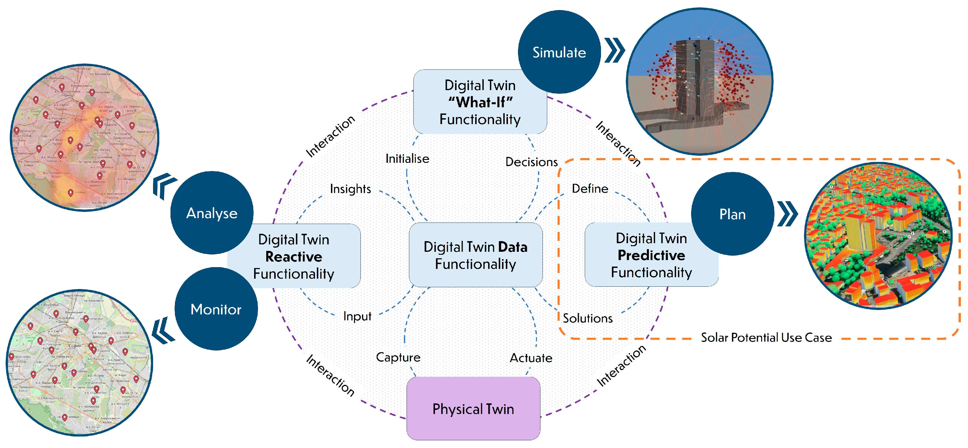
Figure 1. UDT functionality utilisation across different urban scenarios, including solar potential use case.
Remotesensing 16 02700 g001
Figure 2. The scheme of the workflow.
Remotesensing 16 02700 g002
Figure 3. Effective shading terrain surface and 3D terrain generation: (a) viewshed analysis of the terrain shading in QGIS; (b) clipping the terrain with the viewshed (terrain surface clipped the viewshed is presented in green and terrain surface outside the viewshed is presented in blue).
Remotesensing 16 02700 g003
Figure 4. Shading mask according to Global Solar Atlas.
Remotesensing 16 02700 g004
Figure 5. Calculation of incident radiation in Ladybug Tools.
Remotesensing 16 02700 g005
Figure 6. Texture baking in Blender for the study mesh (a), 3134 faces, and the simplification of the mesh, 292 faces(b).
Remotesensing 16 02700 g006
Figure 7. Location of the sample buildings.
Remotesensing 16 02700 g007
Figure 8. Terrain shading in Global Solar Atlas of Building 1 (a) and Building 2 (b).
Remotesensing 16 02700 g008
Figure 9. Input geometry for the study.
Remotesensing 16 02700 g009
Figure 10. Solar incident radiation without shading (a) and with shading (b).
Remotesensing 16 02700 g010
Figure 11. Calculation time and face count: (a) Tregenza sky; (b) Tregenza sky, Reinhart sky, and Reinhart sky with grafting; (c) Tregenza sky without shading geometry and with shading geometry.
Remotesensing 16 02700 g011
Figure 12. (a) solar potential in Rhino; (b) solar potential in ArcGIS Online.
Remotesensing 16 02700 g012
Figure 13. (a) Solar potential in Rhino; (b) solar potential in ArcGIS Online.
Remotesensing 16 02700 g013
Figure 14. Solar potential visualisation in CesiumJS; (a) rooftops of residential buildings in Sofia; (b) building surfaces in the district of Lozenets.
Remotesensing 16 02700 g014
Figure 15. Comparison PC1 and PC2.
Remotesensing 16 02700 g015
Figure 16. Solar analysis of dense photogrammetric meshes.
Remotesensing 16 02700 g016
Table 1. Distant shading. Horizontal plane (roof).
Total kWh, yShading from the TerrainPercentage
Building 1145,570.0877no100.0%
Building 1141,928.7915yes97.5%
Building 2145,456.3552yes99.9%
Table 2. Distant shading. Vertical plane (wall)—south-west direction.
Total kWh, yShading from SWPercentage
Building 1231,873.0974no100.00%
Building 1195,235.4617yes84.20%
Building 2221,454.6975yes95.51%
Table 3. Calculation time for various numbers of faces, sky subdivisions.
Cell Size, mFace CountTr, sTr, Shading, sR, sR, Graft, s
335,93122.522.68484
278,8063049.6180186
1321,574198198840804
0.75568,69237235424002016
0.51,286,308798834--
0.41,988,89715721960--
0.255,146,62233,480---
Table 4. Comparison of the ratio between face count and calculation time.
Study Area, km2Face CountTime, s Ratio Face Count/s
Synthetic buildings0.231,988,89715721265.2
Case 1315.61,909,4991926991.4
Case 213.741,008,5856841474.6
Disclaimer/Publisher’s Note: The statements, opinions and data contained in all publications are solely those of the individual author(s) and contributor(s) and not of MDPI and/or the editor(s). MDPI and/or the editor(s) disclaim responsibility for any injury to people or property resulting from any ideas, methods, instructions or products referred to in the content.