Article

A Priori Estimation of Radar Satellite Interferometry’s Sensitivity for Landslide Monitoring in the Italian Emilia-Romagna Region

1
Department of Civil, Environmental Engineering and Architecture (DICAAR), University of Cagliari, 09123 Cagliari, Italy
2
Department of Civil, Chemical, Environmental and Materials Engineering (DICAM), University of Bologna, 40136 Bologna, Italy
*
Author to whom correspondence should be addressed.
Remote Sens. 2024, 16(14), 2562; https://doi.org/10.3390/rs16142562
Submission received: 22 May 2024 / Revised: 26 June 2024 / Accepted: 10 July 2024 / Published: 12 July 2024
(This article belongs to the Section Engineering Remote Sensing)

Abstract

:
The InSAR technique is known to be a powerful tool for precise monitoring of wide areas in terms of displacements. It is conceivable to also use this technique to monitor landslide areas, but geometrical distortions due to ground morphology and land cover could make InSAR processing ineffective for such applications. Because of the computational burden of InSAR processing, it is important to have preliminary knowledge about the possible suitability of the technique for the inspected area before acquiring and processing the data. This paper aims to perform a preliminary analysis of the InSAR sensitivity for the specific case of landslide monitoring. A new approach is proposed considering aspects specific to landslide displacements, which are basically tangent to the slope direction. Pre-processed coherence maps were used to account for the impact of land cover. The whole analysis can be carried out without acquiring cumbersome SAR datasets and can be used as a preliminary step. The Italian Emilia-Romagna region has been considered as the study area, with landslide areas accounting for more than 12% of its territory. The outcomes show that the inspected area has favourable morphological conditions, mainly thanks to its mild slopes and the limited number of landslides facing north, but the land cover has a strong negative impact on the InSAR sensitivity. Nevertheless, 7.5% of the landslide areas have promising conditions for monitoring using radar interferometry.

1. Introduction

Among natural disasters, landslides represent critical phenomena considering both their global occurrence and their related hazards and risks [1]. Italy is the European country with the highest rate of landslide occurrence, especially considering mountainous and hilly areas, covering about two-thirds of the total surveyed phenomena in Europe [2]. In particular, Emilia-Romagna is one of the most significant regions in Italy in terms of landslide area diffusion: geological maps indicate a total of about 79,000 landslide features, equal to 23% of the regional land surface [3]. Regional authorities are therefore involved in the assessment and evaluation of the landslide phenomena, producing updated maps and inventories representing their spatial distribution and geometrical characteristics [4]. Moreover, these inventories aim to catalogue the existing landslide deposits by distinguishing between the different types of movements and involved material, representing fundamental data sources for any study concerning landslide-related analysis and risk assessment [1,4,5]. The currently active landslides in the Emilia-Romagna region are mainly due to reactivation phenomena in previously existing unstable situations related to strong precipitation or the melting of significant snowpacks [6]. These events usually induce surface expansions and the overlapping of several accumulating areas, inevitably leading to huge damage to inhabited areas, industrial activities, and infrastructure [7]. Moreover, landslide phenomena and related hazards can be strongly enhanced by other factors like heavy precipitation, earthquakes, and human activities [5,8,9]. Indeed, recent events that occurred in May 2023 in the Emilia-Romagna region are an example of how climate change, strong urbanization, and deforestation can intensify the issues related to landslide phenomena.
In this context, mapping and monitoring landslide areas are essential supporting activities in assessing their physical mechanisms (i.e., the velocity of movement, the evolution over time), allowing for proper land use planning and defense to prevent or mitigate possible risks [1]. The integration of historical, geomorphological, hydraulic, and climatic data is necessary for dealing with complex studies related to landslide phenomena. All the mentioned information can be efficiently handled by means of Geographic Information Systems (GISs), ensuring the proper management of different reference systems [10].
The difficult accessibility of landslide areas, and the potential correlated risk, commonly makes their characterization challenging [4]. Several possibilities exist in terms of the measuring techniques usable for these applications which ensure high levels of accuracy. These include the use of in situ Global Navigation Satellite System (GNSS) receivers, aerial and terrestrial photogrammetry through the Structure from Motion (SfM) approach, Terrestrial LiDAR (Light Detection and Ranging), the employment of classic topographic instruments (i.e., Total Stations), and remote sensing techniques. All the mentioned technological solutions can be employed both to map the spatial distribution of landslide areas (i.e., inventory maps) and to identify their movements (i.e., monitoring applications). Nevertheless, the areas of interest are usually hardly accessible, making the use of some geomatic techniques potentially ineffective, too expensive, or even unfeasible [8,11]. This fact is particularly true for those techniques which imply surveyors’ access to the area to be monitored, such as Total Stations, Terrestrial LiDAR, and the use of GNSS receivers. Moreover, the measurement frequency and the number of monitored points are restricted in the case of using classic topographic techniques or GNSS acquisitions, thus limiting the extension of the area and the capability to describe displacements over a non-rigid sliding body. Furthermore, in the case of ground measurements, the field of view of the instrument, as well as the possible lack of supporting networks, could represent a limiting factor for survey realization.
Remote sensing techniques inherently solve these problems related to accessing areas and the inter-visibility between instruments, while the availability of several satellite sensors offering a revisiting time of one/two weeks allows for frequent and effective monitoring. Among the possible remote sensing techniques, in recent years, Radar Satellite Interferometry (InSAR) has gained interest in the scientific community, and several research works have proved the effectiveness of its application to landslide movement monitoring worldwide [8,9,11,12,13,14,15,16].
Unlike optical remote sensing, SAR satellites are able to collect data regardless of the presence of external electromagnetic energy sources and under any weather conditions, ensuring continuous acquisitions with global coverage. SAR satellites generate two types of 2D images: one type that includes the amplitude of the reflected radar signal and one type that reports the phase of the signal. To obtain displacement information, SAR acquisitions are processed by applying the principles of differential interferometry, i.e., DInSAR.
Based on the wavelength of the radar signals, the InSAR technique is in principle capable of observing sub-centimeter displacements [17]. Amplitude and phase images together are used to spot so-called persistent scatterers (PSs): image pixels which are stable in amplitude and coherent in phase and therefore have a high probability of referring to the same object on the ground [18]. SAR satellites follow polar orbits, thus moving south to north in so-called “ascending” acquisitions and north to south in “descending” ones (see Figure 1a). SAR sensors are based on side-looking geometry: the Line of Sight (LOS) is usually oriented to the right side with respect to the traveling direction of the satellite (azimuth direction), with a certain incidence angle to the ground (see Figure 1b). The viewing geometry is thus defined by two main parameters: the heading and incidence angles [19].
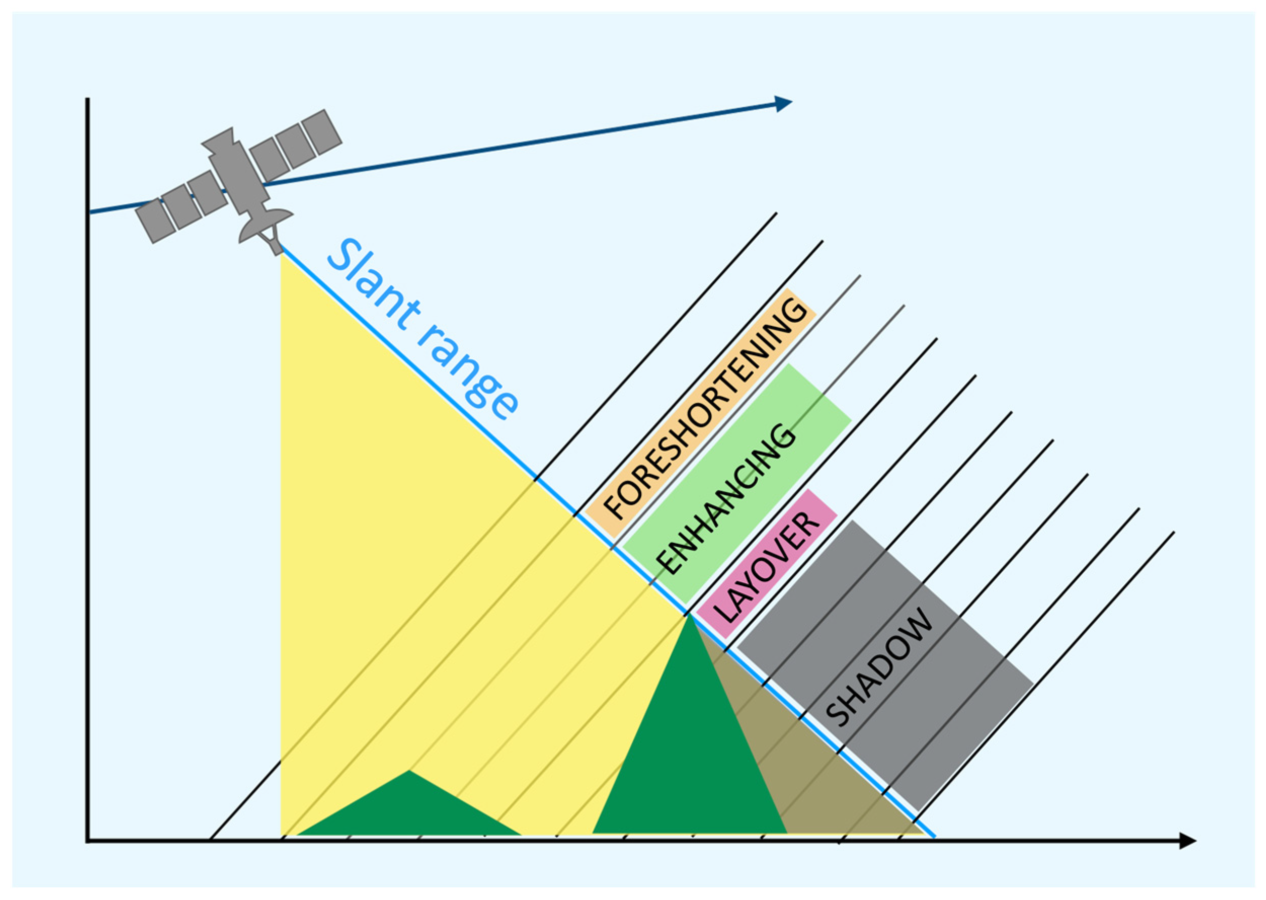
Side-looking SAR sensors induce distortions and blinding effects like those shown in Figure 2, in particular foreshortening, layover, and shadow. Foreshortening areas are the ones exposed to the LOS direction. In this case, a small difference in range involves a surface much wider than that in flat terrain, thus causing a reduction in the ground resolution of the SAR images. On the opposite side, hillsides facing the direction opposite to the satellite are represented at an increased resolution. Layover and shadow effects happen when the topography is characterized by strong height variations. In the first case, points at high elevation reflect signals at the same time as some points geographically closer to the sensors, thus making it impossible to detect their correct ground position. Finally, points laying on steep slopes not facing the satellites cannot be hit by the radar signals and then remain in shadow, so the SAR sensor is blind to these areas [20].
Furthermore, displacements in the LOS directions can be split between the vertical and plane directions using PSs detected in both the ascending and descending geometries [21].
Considering the almost polar directions of the satellite orbits, the displacements along the plane component are almost fully hidden in the north–south direction. Thus, landslide slopes facing north or facing south cannot be monitored since sliding displacements will not induce variations in the SAR phase. On the other hand, slopes facing the sensors whose sliding surfaces are orthogonal to the LOS also cannot be efficiently monitored for the same reason.
Reasonably, SAR acquisitions over hilly and mountainous areas are vulnerable to strong geometrical distortions due to their steep and rough topography, which cannot be avoided [9,12]. Besides this, the performance of the InSAR measurements depends on other factors like the presence of vegetation cover, which is particularly relevant when dealing with mountainous environments [5,9,12]. For these reasons, several studies have recently explored the potential of landslide monitoring using the InSAR technique, mainly considering a priori evaluation of geometric distortions’ occurrence based on the local topography [22,23,24]. Other works, such as [25], have investigated the correlation between InSAR coherence and vegetation coverage, highlighting the impact of vegetation on landslide detection. In [26], a methodology for assessing the applicability of InSAR to landslide deformation a priori at a global scale was presented based on the sensitivity index proposed in [27].
The aim of this paper is to analyze the possibility of using the SAR remote sensing technique to monitor landslides over the Emilia-Romagna territory, knowing that such a technique only provides insights into geometrical displacements, which should be integrated with other sources of information and geological considerations. This study helps us figure out in which areas InSAR can be considered more or less sensitive by evaluating factors such as the ground topography and the land cover. The ground topography, available from Digital Elevation Models (DEMs), impacts the distortion and blinding effects related to the satellite geometries. In particular, critical effects like shadow, layover, and foreshortening are considered, besides the orientation of the landslide slopes with respect to the satellite’s azimuth. This problem has already been addressed in other papers [4,28,29,30,31,32,33,34]. Furthermore, the ground coverage and the presence of structures or infrastructure impact the probability of finding a sufficient number of PSs over the inspected area, which enable the use of the InSAR technique.
This issue has already been addressed by Colombo et al., 2006 [35]. Over the years, however, several InSAR processing services have been made available to users. In particular, the Centre for Observation and Modelling of Earthquakes, Volcanoes and Tectonics (COMET) has created LiCSAR [36], a portal through which users can download InSAR products. These include coherence maps from which reliable information on the presence or absence of PSs can be extracted [37]. The pixel coherence in time and space, given by the web service (https://comet.nerc.ac.uk/comet-lics-portal/, accessed on 1 May 2024), was thus used to predict the availability of PSs over the study area, which varied based on the land cover.
In our analysis, we considered the satellite geometry of the Sentinel-1 SAR mission since it provides open data, and free open-source software are available for their processing. Sentinel-1 includes twin satellites, Sentinel-1A and Sentinel-1B, which have been fully operational since 2016 [38]. The mission is part of the Copernicus project, the Earth Observation component of the European Union’s space programme, that aims at developing information services based on satellite Earth Observation data.
In the following, a detailed description of the data sources used for the analysis is provided, and then three independent parameters considering both topography and land cover are proposed and combined to form an overall SAR Landslide Sensitivity Index (SLSI). Results on the computation of these parameters for the Emilia-Romagna territory will be discussed and compared to what can be obtained by using the globally available service from Van Natijne et al. [26].

2. Materials and Methods

In the first part of this section, details on the dataset and a priori information used in the analysis are provided. Then, in the second part, the parameters used to estimate the SAR sensitivity for landslide monitoring are defined.
The dataset we used to analyze the specific case of the Emilia-Romagna region is made of a DEM and a landslide inventory. We used the Digital Terrain Model provided by the regional website of Emilia-Romagna [39], which results from LiDAR surveys performed in the year 2009 and has a spatial resolution of 5 × 5 m.
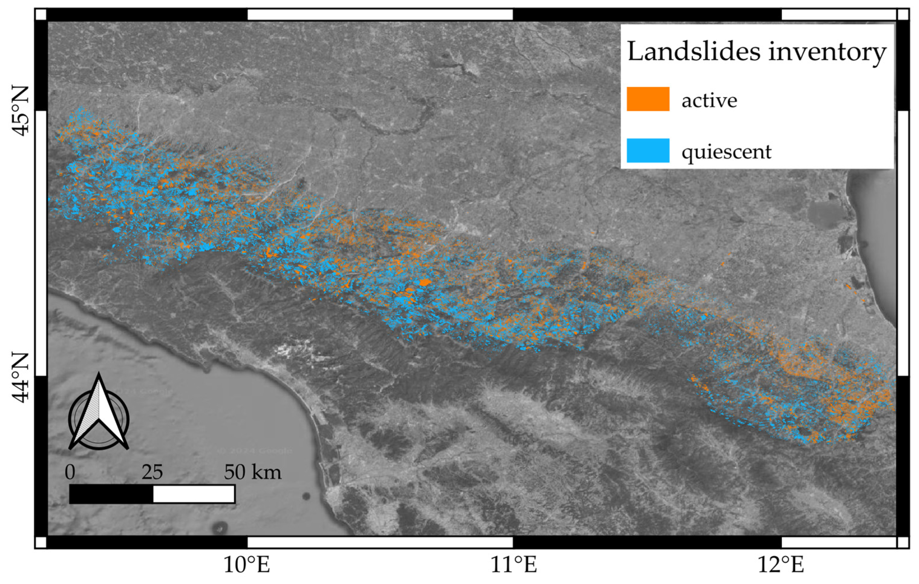
The landslide inventory is a vector layer produced starting from geological survey campaigns supplemented by aerial images. This database is constantly updated through local studies, technical reports, inspections, survey data, and aerial and satellite image analysis coupled with historical cartographic sources [40]. Each landslide feature (i.e., its corresponding polygon) is classified according to the area, linear extension, the synthetic description of its movement, and the state of its activity (e.g., active or reactivated, quiescent, stabilized, and undetermined). A total of 117,882 landslide features have been identified in the Emilia-Romagna region. For this study, we only considered those classified as “active” or “quiescent” (Figure 3), covering a surface of about 2750 km2, which means 12% of the regional area.
Finally, we considered the SAR geometry for the Sentinel-1 Wide Swaths (IW) acquisitions using the two local values for the heading angle, namely −14° for the ascending orbit and −166° for the descending orbit. The incidence angle has been considered in its local value, which changes depending on the DEM pixel distance from the ground projection of the satellite orbits.
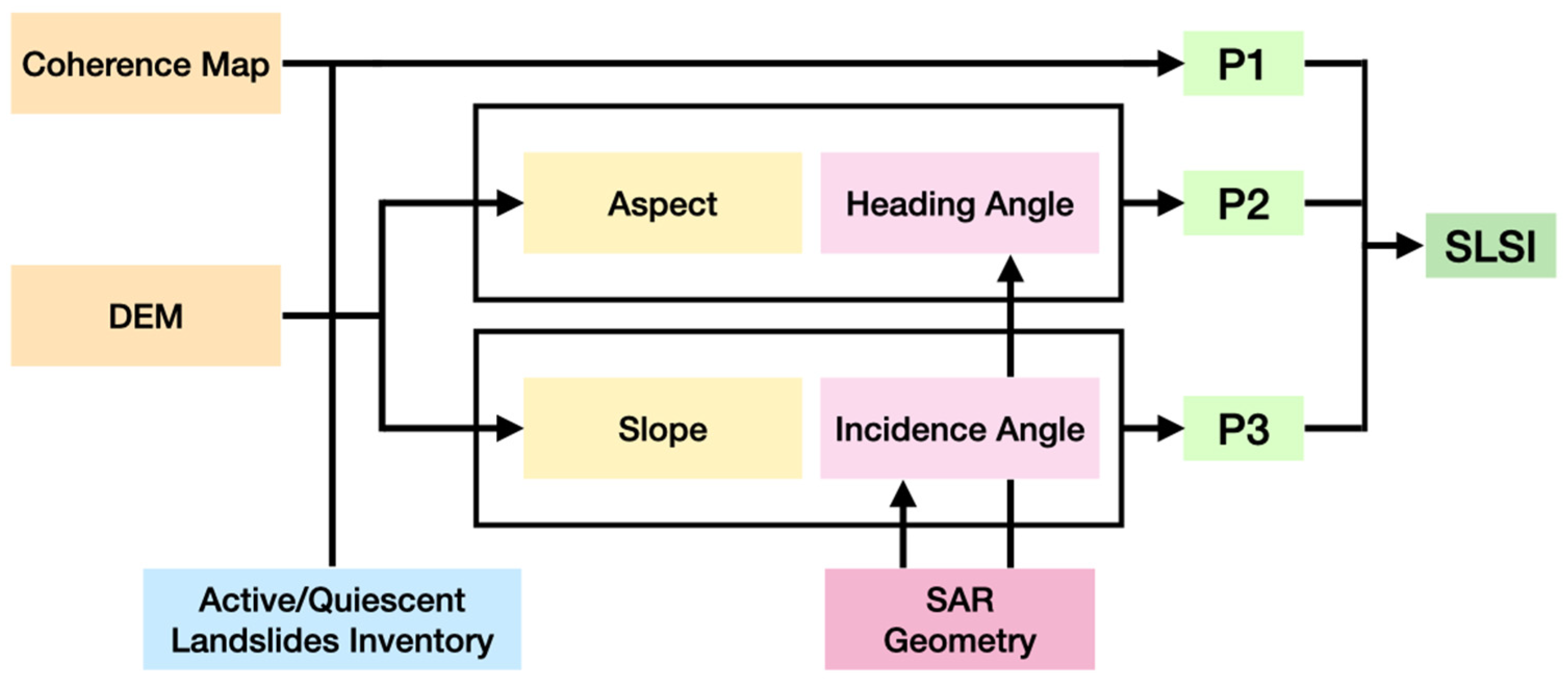
Three independent parameters have been defined starting from these data sources. Coherence maps from the LiCSAR database were used to define P1, while the SAR geometry and the DEM were used to compute parameters P2 and P3 (see Figure 4), hereafter described in detail. These parameters were computed pixel by pixel according to the DEM’s 5 m × 5 m spatial resolution. The geospatial elaborations were performed using the open-source software package QGIS 3.34.8 [41] and by exploiting ad hoc Python (3.8 version) scripts based on GIS modules.

2.1. P1—SAR Land Cover Sensitivity

The P1 parameter aims to define a coefficient describing the expected probability of a certain area having SAR persistent scatterers describing the local displacements. Even though it is known how the specific InSAR processing techniques [42,43,44,45] and parametrization can strongly impact the number of PSs found in the same area, we assumed the coherence maps to be a reliable source for investigating the probability of effective SAR processing in a specific area. In particular, we have chosen to set the P1 value to zero for pixels where the coherence value is below 0.05, while P1 is set to one for values exceeding 0.1. Then, the P1 values vary linearly between the two thresholds. These were set considering that 0.05 is a lower bound for reliable unwrapping [46], whereas a coherence higher than 0.1 is said to imply limited errors in that same crucial processing phase [37]. The ground sampling of the LiCSAR products is 100 × 100 m, much coarser than the 5 × 5 m resolution of the DEM. Each DEM pixel belonging to the same 100 × 100 m tile has been assigned the same P1 value.

2.2. P2—A Dip Orientation Parameter

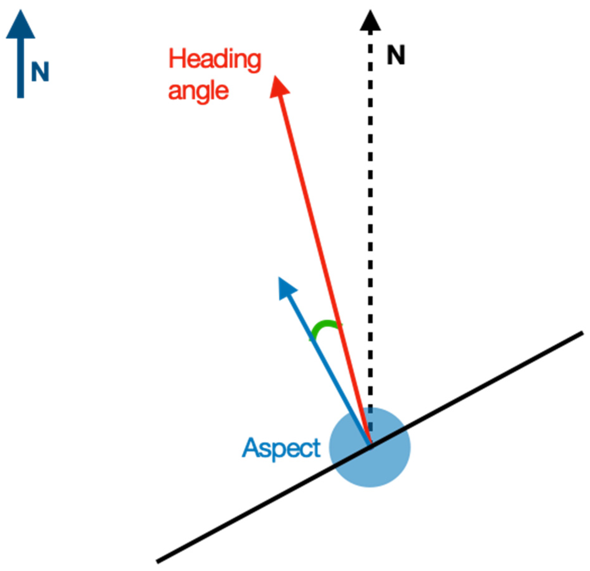
The P2 parameter accounts for the landslide orientation with respect to the SAR satellite’s heading direction. In particular, the average dip direction for each landslide feature was derived using the Aspect Qgis tool, which computes it for each pixel of a DEM raster. Then, the dip direction was compared to the satellite heading, both for the ascending and descending geometries (Figure 5), by computing the α angle:
α a s c / d e s c i = h e a d i n g a s c / d e s c d e e p i ,
The P2 coefficient value should be maximum when the landslide surface faces the SAR sensor and null if the dip direction is 90° to the satellite heading. Knowing that the latter condition is critical for angles very close to 90°, but it will improve more than linearly when α moves to zero, we defined the weight for P2 as follows:
P 2 a s c / d e s c i = s i n ( α a s c / d e s c ) ,
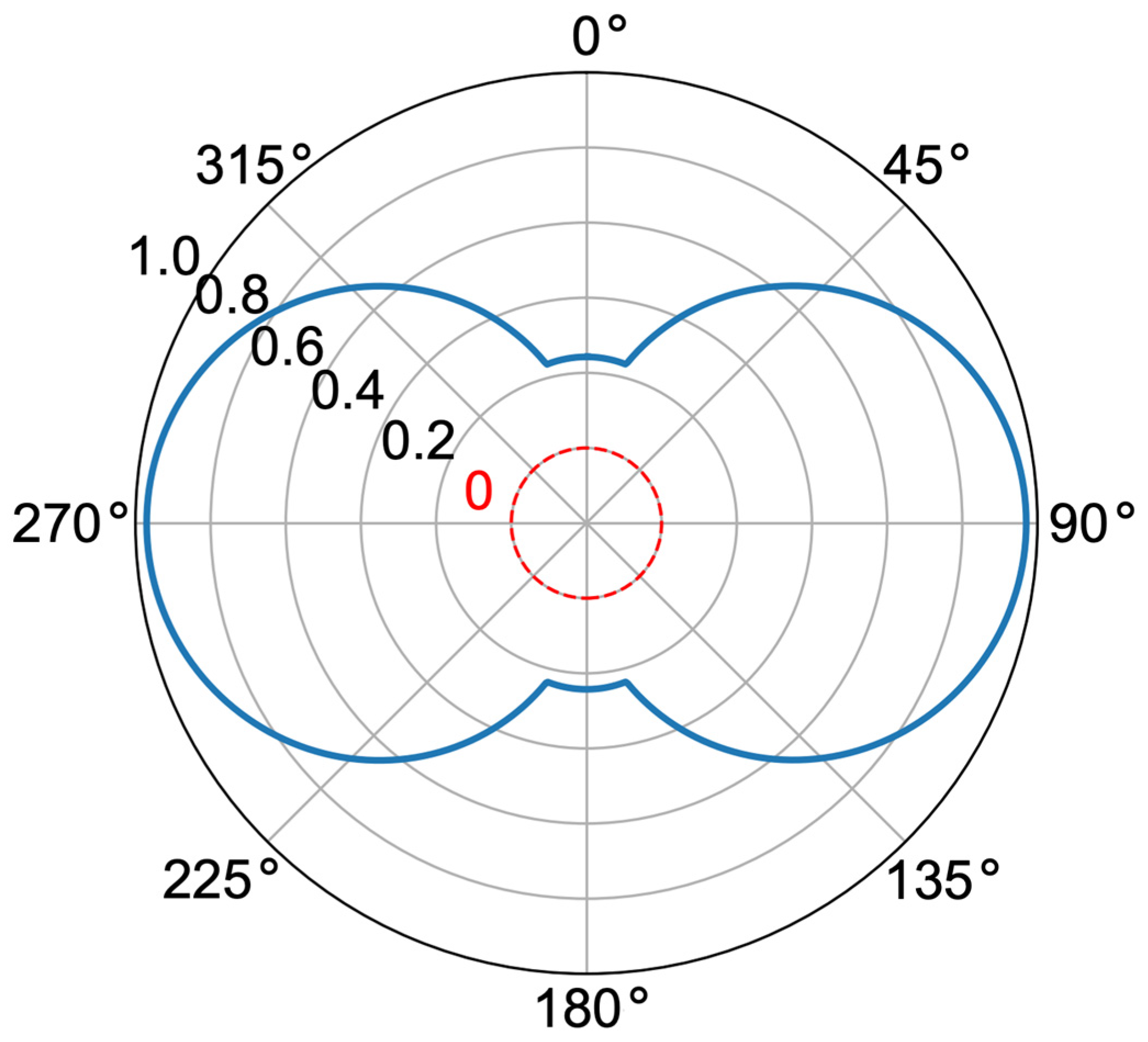
Finally, for each pixel i , the P2 coefficient is obtained by averaging the P 2 a s c i and P 2 d e s c i values. Figure 6 shows the variation in P2 values depending on the azimuth of the landslide dip direction.

2.3. P3—A Slope Immersion Parameter

The P3 parameter considers the relation between the immersion of each landslide and the local SAR incidence angle. The Slope Qgis function was used to retrieve, again from the DEM layer, the immersion angle (slope) for each pixel, which ranges from 0° (flat) to a maximum of 90° [41].
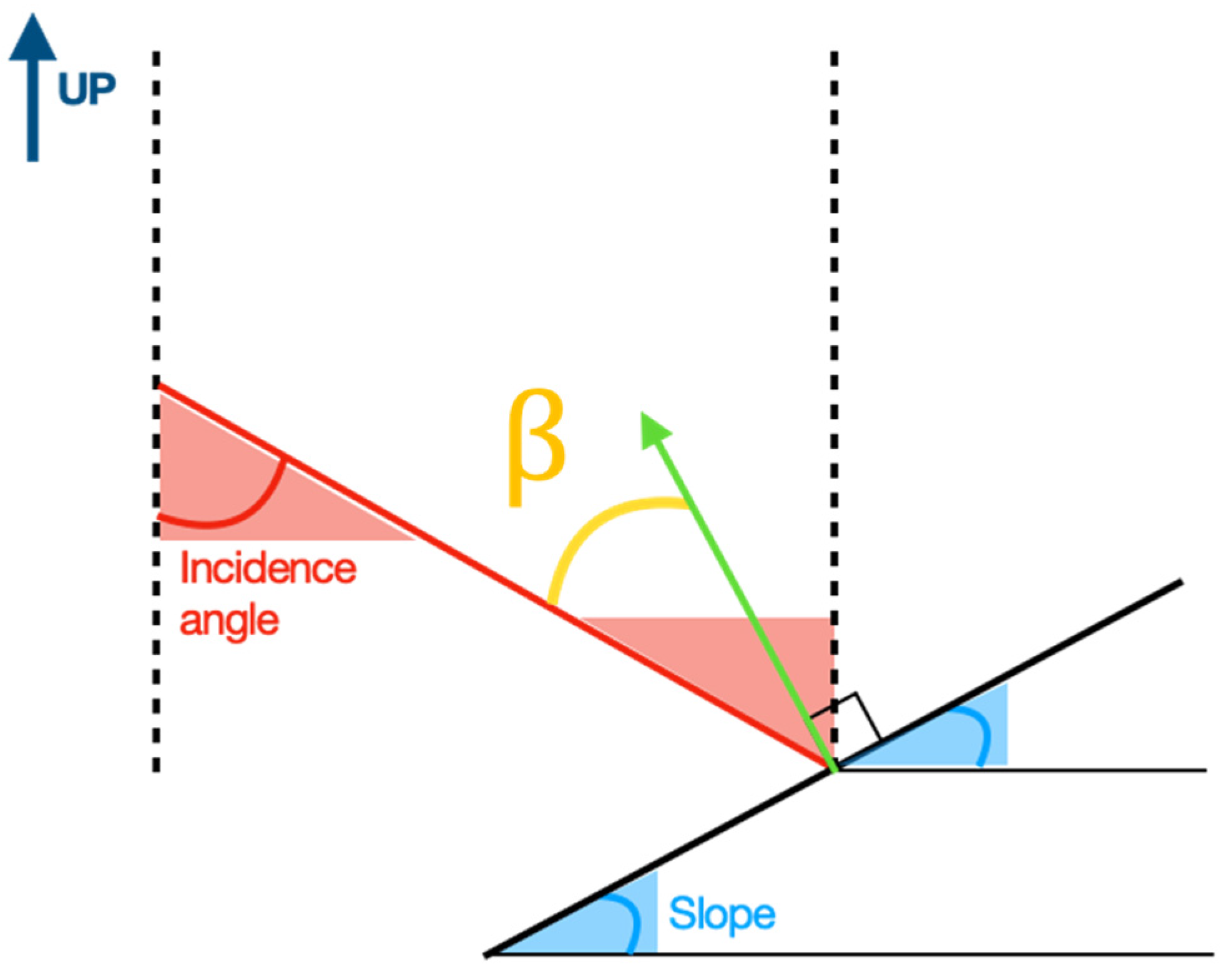
We then defined the angle β from the LOS direction against the orthogonal to the immersion direction of each landslide (see Figure 7). The P3 weight was then assigned depending on the β angle and considering that (i) for sliding directions orthogonal to the LOS, displacements cannot be detected in terms of phase variations since the range does not change; (ii) areas in “shadow” conditions, namely β > 90 ° , are hidden from the SAR sensor; and (iii) slopes in the “enhancing” condition are easier to monitor than those in “foreshortening” (see Figure 2). Therefore, we defined the P3 values as follows:
90 ° i n c β < 0 P 3 a s c / d e s c = β 90 ° i n c . 0 β β c P 3 a s c / d e s c = β β c β c < β < 90 ° P 3 a s c / d e s c = 90 ° β 90 ° β c β 90 ° P 3 a s c / d e s c = 0 ,
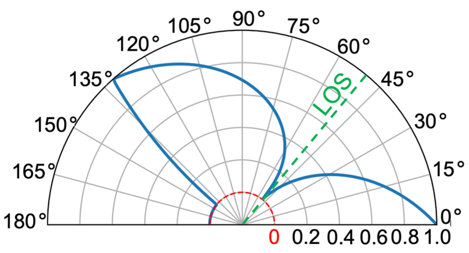
where β c is a critical value for β that we now set to 80°. β c has been introduced so that terrains very close to the shadow condition cautiously are not considered optimal because of the possible shadowing due to terrain roughness, isolated rocks, or trees in the area above. Figure 8 shows how the P 3 a s c / d e s c value changes depending on the β angle.
The same calculus was carried out for each landslide, both for the ascending and descending geometries, and the final P3 values were computed by averaging P 3 a s c i and P 3 d e s c i . The choice to average values from the ascending and descending geometries accounts for the fact that having both data on the same surface allows for better monitoring and also allows splitting displacements into vertical and horizontal directions, but sliding movements can be monitored just using a single LOS acquisition anyway.

2.4. Parameter Integration and Final Index (SLSI)

Finally, the three parameters (P1, P2, and P3) have been integrated into a single index named the SAR Landslide Sensitivity Index (SLSI), with positive values ranging between 0 and 1:
S L S I = P 1 · P 2 · P 3 ,
The choice to have multiplying factors is driven by the need to have a null final value in cases in which any of the parameters are zero, equating to the impossibility of monitoring the related landslide through SAR measurements. SLSI was computed for each 5 m × 5 m pixel. Then, to define the level of monitorability of each landslide, the SLSI values were averaged over the best 5% of pixels belonging to each of them. This let us consider a sufficient number of PSs without discarding the possibility of monitoring a landslide because of a suboptimal average SLSI value. In the case of small landslides, the 5 pixels with the highest SLSIs were considered instead to guarantee the minimum number of representative measuring points.

3. Results

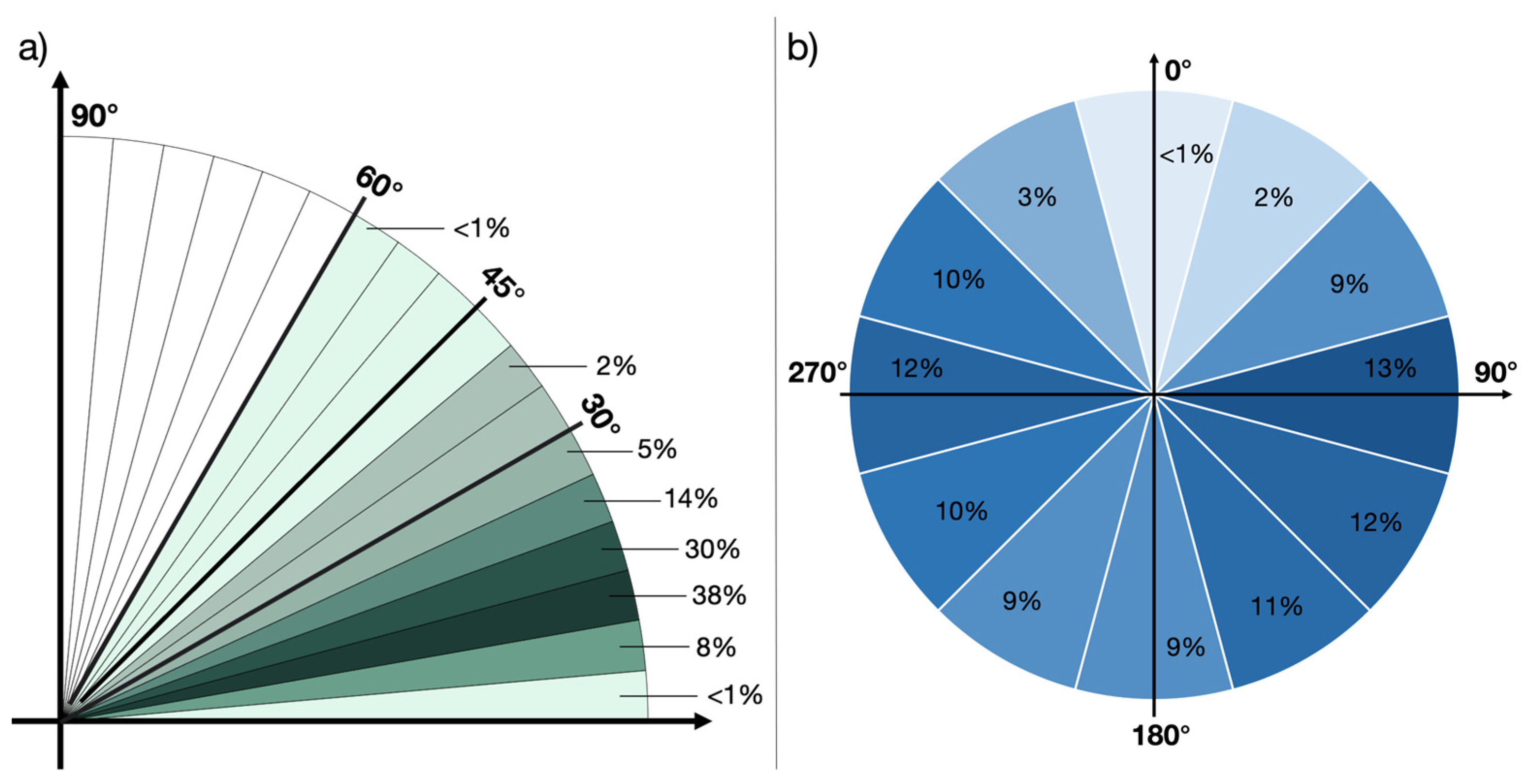
In this section, the outcomes from the analysis performed in the Emilia-Romagna region following the above-described approach are presented. First, the terrain geometry over the landslide areas shows a mild topography, with most of the slope angles within 45°, which means shadowing effects in the SAR acquisitions are avoided, while less than 5% of the landslide slopes exceed this value, as shown in Figure 9a. The dip direction angles are more varied, as shown in Figure 9b, with a higher percentage aligned with the east–west direction and more landslides facing south compared to those oriented towards the north. This geometrical set is rather convenient considering the characteristic heading angles of the SAR satellites.
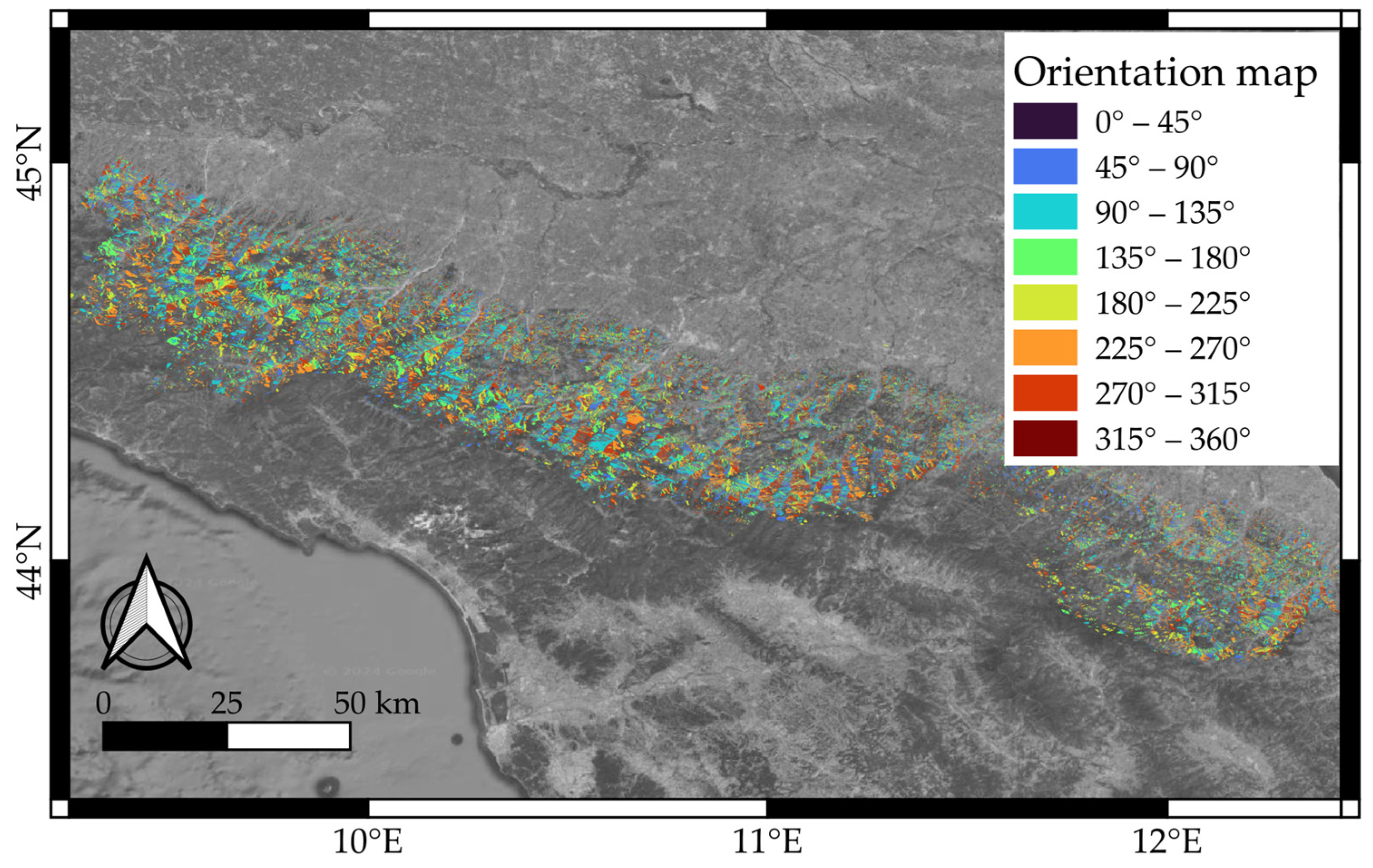
Figure 10 gives an overview of the spatial distribution of the landslide orientations, which are almost homogeneously distributed over the hilly areas of the region.
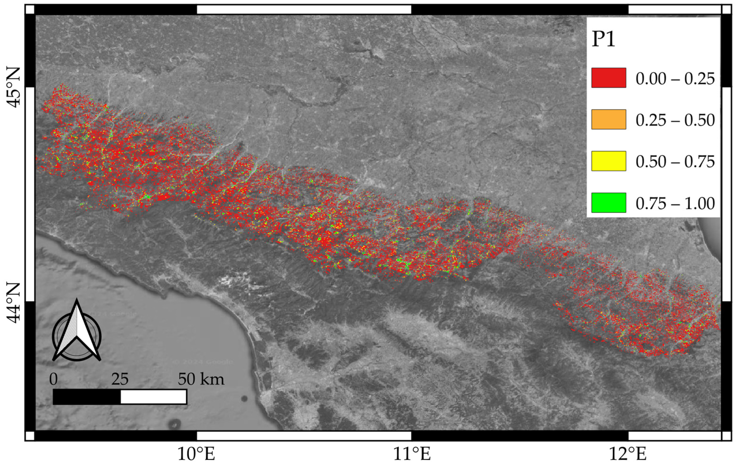
As for the analysis of the probability of having PSs in the inspected area, the results in terms of P1 are presented in Figure 11. There, four classes are used to classify the Emilia-Romagna landslides pixel by pixel. Most of them belong to the Appennino Tosco-Emiliano hilly area, where there is a prevalence of vegetation and a poor presence of urban infrastructure.
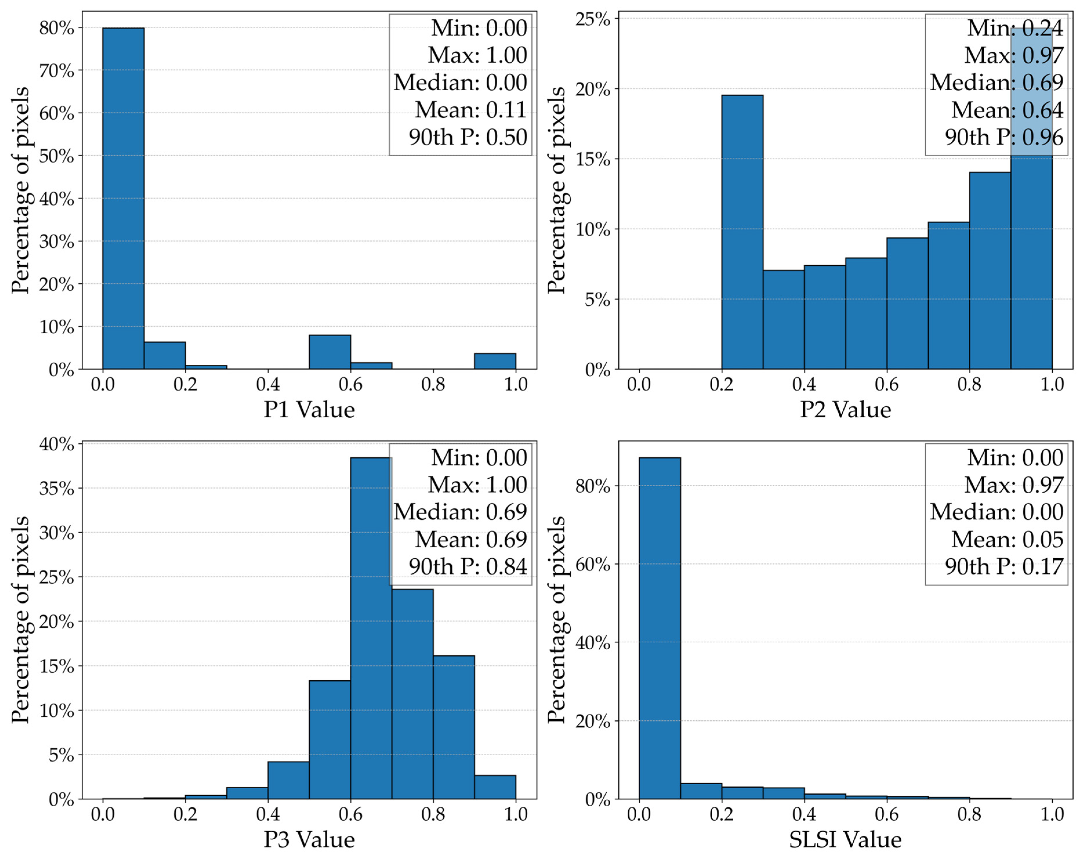
The top left of Figure 12 reports a histogram of the P1 values over the whole set of pixels belonging to the landslide areas. The median of their distribution is zero, meaning that more than half have a P1 equal to zero, while almost 80% have a P1 below 0.1. Only 10% of pixels have P1 values above 0.5, with 4% of them between 0.9 and 1.
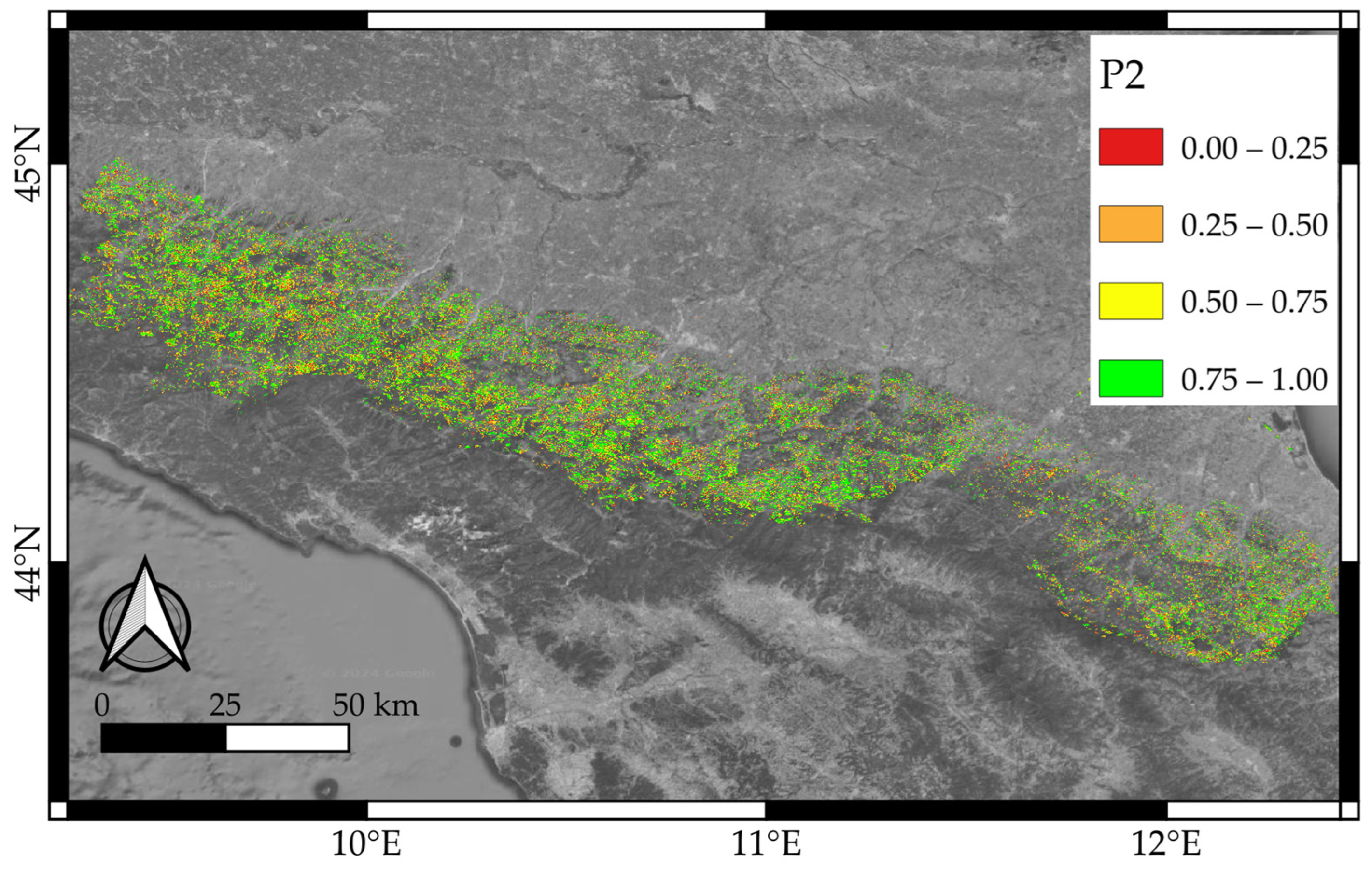
The results in terms of parameter P2 are shown in Figure 13, and the related histogram is top-right in Figure 12 As expected, the orientation of the slopes in the inspected area is favorable for SAR monitoring in most of the cases: half of the landslide pixels have a P2 value higher than 0.69, and in almost 24% of cases, P2 remains above 0.9.
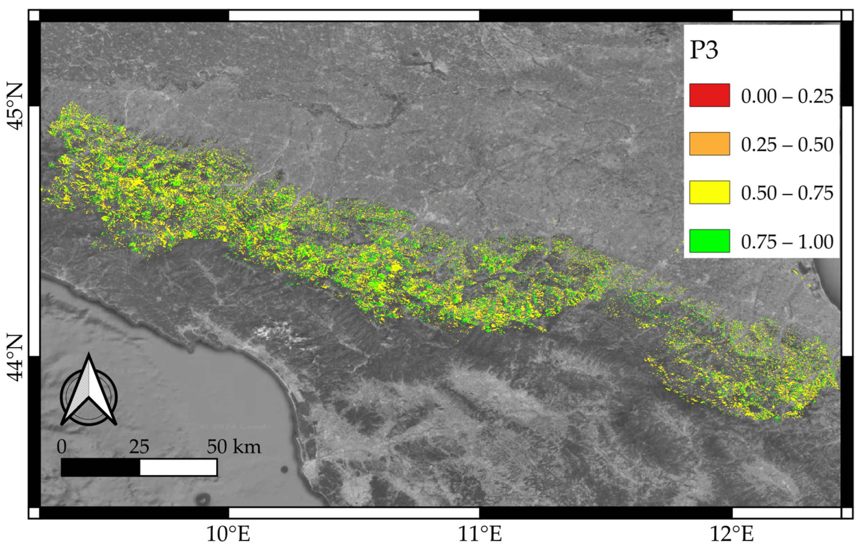
The P3 parameter (Figure 14) mainly takes values between 0.6 and 0.8, and in less than 1% of the cases, it is below 0.3 (see bottom left of Figure 12). Half of the P3 values are above 69%, thus showing an overall promising condition from the point of view of slopes.
Finally, the pixel-by-pixel results of computing SLSI for the inspected region are depicted in the bottom-right histogram in Figure 12. Most of the pixels have SLSIs equal to zero, and only 10% of them are rated above 0.17. These results are mainly affected by the P1 parameter, somehow related to the land cover. In particular, the pixels with higher values in terms of P1 unfortunately belong to unfavorable geometries for which P2 or P3 is very low.
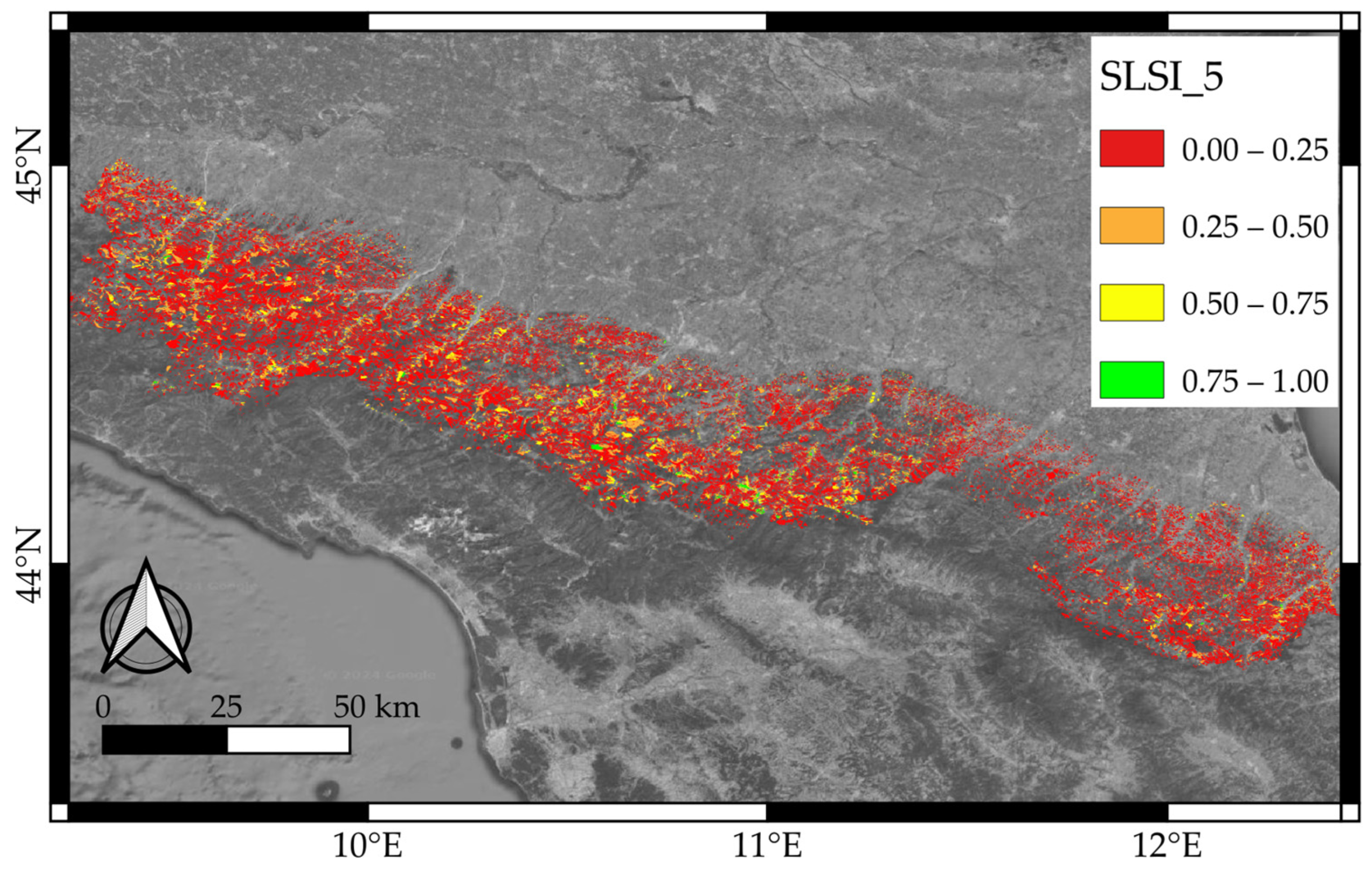
Then, the results in terms of the estimated monitorability of each landslide body are reported in Figure 15 and Table 1. There, values are referred to as the average SLSI over the 5% of pixels, or at least 5 pixels in cases of landslides covering fewer than 100 pixels, with the highest values. Almost 75% of the Emilia-Romagna landslides have a SLSI5 value lower than 0.25, while only 680 of them can be considered under optimal conditions for SAR monitoring. Overall, 18% of the landslides have SLSI5 values between 0.25 and 0.5 and could possibly be monitored, whereas another 6% have a good probability of having enough effective PSs across them.

4. Discussion

The InSAR technique is a powerful instrument allowing us to observe surface changes over large areas without heavy or risky field operations, although it is known that it suffers from some inherent geometric constraints which make data processing and interpretation challenging. This paper aims at a preliminary evaluation of the feasibility of landslide monitoring using SAR data over the Emilia-Romagna region. A specific approach to performing such an evaluation was introduced in the paper. Even though this approach can be applied to any SAR constellation, it was applied to the Sentinel-1 mission, which provides open data and can be used by many researchers or public administrations. The computation of SLSI for the considered area shows that most of the landslides are hardly monitorable by InSAR, but such a result mainly depends on the impact of the P1 parameter, the one related to land cover and the expected number of PSs. It is worth a reminder that such a parameter has been defined starting from coherence maps available online to all users, avoiding the need to acquire SAR raw observations and process them. As was defined in Section 2.1, P1 can be considered rather optimistic; therefore, landslides with low P1 values will actually be hard to monitor with good reliability. As for the application of the method to the Emilia-Romagna region, we also restricted the analysis to active landslides only (see Figure 3), those with the greatest need to be monitored, but statistically, almost the same results were found in terms of SLSI5.
We also wondered what the scenario would be considering the geometrical aspects only; thus, the P2 and P3 parameters were multiplied so as to compute the results listed in columns 2 and 3 of Table 2. More than 95% of these values are between 0.25 and 0.75, showing that most of the landslides in the region are virtually monitorable by SAR from the geometrical point of view, while in only 4% of the cases is the terrain morphology a limiting factor.
We then compared these results to those retrieved by using the service available worldwide (https://data.4tu.nl/articles/dataset/World-wide_InSAR_sensitivity_index_data_set_for_landslide_deformation_tracking/14095777/1, accessed on 1 May 2024) described in [26]. We computed the sensitivity index (s) on the web service for the whole Emilia-Romagna region and cropped the results by using the same landslide inventory considered in our work. Table 2 reports the obtained results in terms of “s” in columns 4 and 5, confirming that most of the landslides have a sensitivity index between 0.25 and 0.75. Differences in the two analyses are probably due to (i) the different definitions of the sensitivity index, mainly in terms of the relation between the immersion angle and the incidence angle (our P3), and (ii) the different resolutions of the DEMs used to compute the local geometrical parameters.
This study provides insights into which areas are more well suited to being monitored by integrating InSAR displacement information into other geological analyses. Further studies could be undertaken hypothesizing about InSAR processing to evaluate a posteriori the relation between the number of PSs and the land cover and the actual reliability of using coherence information to predict the presence of PSs, while also considering that different types of processing have different responses. Moreover, the possibility of placing ad hoc corner reflectors in the inspected areas and the evaluation of their impact in improving the SAR sensitivity should be considered.

5. Conclusions

This paper addresses the problem of defining an a priori estimation of the effectiveness of InSAR processing in landslide monitoring. The case study of the Emilia-Romagna region is considered, exploiting an ad hoc high-resolution DEM to compute the geometric distortions. Many other papers [4,5,9,20,29,47,48] have already addressed the impact of the ground morphology on InSAR processing, but this was mainly approached by considering satellite geometric distortions (SGDs) like foreshortening, layover, and shadow or the apparent slope [26]. These aspects impact the possibility of defining stable and reliable PSs in the inspected scene, but they do not consider the SAR’s sensitivity to the displacements characterizing landslides, namely tangent to the slope plane. Differently, the parameter P3 proposed here also focuses on the sensitivity in terms of SAR phase variations with displacements happening along the sliding surface. In some cases, the land cover usage was also considered [30,35], but here, the actual ground response to radar signals has been integrated into the analysis, starting from already available coherence maps. The strength of this paper is its proposal of the combination of all the aspects discussed into a common analysis, specific to landslide monitoring applications. Overall, this work provides a method for performing an inexpensive pre-processing analysis specific to the area to be inspected based on open data to provide insights into the feasibility of InSAR monitoring before taking on the effort of interferometric processing. In the specific case of the Emilia-Romagna landslides, mainly due to land cover, only 7.5% of the landslides are expected to be effectively monitorable through InSAR. This work helps identify those areas where successful monitoring can be expected.

Author Contributions

Conceptualization and methodology, L.T. and E.V.; software computation and validation, E.V.; investigation, E.G. and E.V.; resources and data curation, E.V. and E.G.; writing—original draft preparation, L.T. and E.V.; writing—review and editing, E.G. and S.G.; visualization, E.V. and E.G.; supervision, S.G. All authors have read and agreed to the published version of the manuscript.

Funding

This research received no external funding.

Data Availability Statement

DEM data are available through the public regional service at https://geoportale.regione.emilia-romagna.it (accessed on 1 May 2024). SAR Coherence maps can be downloaded from the scientific open service via https://comet.nerc.ac.uk/comet-lics-portal/ (accessed on 1 May 2024). Already available sensitivity maps are accessible through the web service at https://avannatijne.users.earthengine.app/view/landslide-insar (accessed on 1 May 2024).

Conflicts of Interest

The authors declare no conflicts of interest.

References

  1. Guzzetti, F.; Carrara, A.; Cardinali, M.; Reichenbach, P. Landslide hazard evaluation: A review of current techniques and their application in a multi-scale study, Central Italy. Geomorphology 1997, 31, 181–216. [Google Scholar] [CrossRef]
  2. EuroGeoSurveys. Available online: http://m.eurogeosurveys.org (accessed on 1 September 2023).
  3. Gozza, G.; Pizziolo, M. 13. Analisi del Dissesto da Frana in Emilia-Romagna. 2006. Available online: http://isprambiente.gov.it (accessed on 1 December 2023).
  4. Aslan, G.; Foumelis, M.; Raucoules, D.; De Michele, M.; Bernardie, S.; Cakir, Z. Landslide mapping and monitoring using persistent scatterer interferometry (PSI) technique in the French Alps. Remote Sens. 2020, 12, 1305. [Google Scholar] [CrossRef]
  5. Kalia, A.C. Classification of landslide activity on a regional scale using persistent scatterer interferometry at the Moselle valley (Germany). Remote Sens. 2018, 10, 1880. [Google Scholar] [CrossRef]
  6. Ambiente Regione Emilia-Romagna. Available online: https://ambiente.regione.emilia-romagna.it (accessed on 1 September 2023).
  7. Servizio Geologico Sismico e dei Suoli (SGSS). Le Frane. 2016. Available online: https://ambiente.regione.emilia-romagna.it/it/geologia/pubblicazioni/opuscoli/le-frane-2016 (accessed on 31 May 2016).
  8. Kuang, J.; Ng, A.H.-M.; Ge, L. Displacement characterization and spatial-temporal evolution of the 2020 Aniangzhai landslide in Danba county using time-series InSAR and multi-temporal optical dataset. Remote Sens. 2021, 14, 68. [Google Scholar] [CrossRef]
  9. Hussain, S.; Pan, B.; Afzal, Z.; Ali, M.; Zhang, X.; Shi, X. Landslide detection and inventory updating using the time-series InSAR approach along the Karakoram Highway, Northern Pakistan. Sci. Rep. 2023, 13, 7485. [Google Scholar] [CrossRef] [PubMed]
  10. Gussoni, M.; Turconi, L. Frane, il GIS a supporto della conoscenza. Ecoscienza 2015, 3, 23–24. [Google Scholar]
  11. Carlà, T.; Intrieri, E.; Raspini, F.; Bardi, F.; Farina, P.; Ferretti, A.; Colombo, D.; Novali, F.; Casagli, N. Perspectives on the prediction of catastrophic slope failures from satellite InSAR. Sci. Rep. 2019, 9, 14137. [Google Scholar] [CrossRef]
  12. Sun, Q.; Hu, J.; Zhang, L.; Ding, X. Towards slow-moving landslide monitoring by integrating multi-sensor InSAR time series datasets: The Zhouqu case study, China. Remote Sens. 2016, 8, 908. [Google Scholar] [CrossRef]
  13. Kiseleva, I.; Mikhailov, V.; Smolyaninova, E.; Dmitriev, P.; Golubev, V.; Timoshkin, E.; Hooper, A.; Samiei-Esfahany, S.; Hanssen, R. PS-InSAR monitoring of landslide activity in the Black Sea coast of the Caucasus. Procedia Technol. 2014, 16, 404–413. [Google Scholar] [CrossRef]
  14. Béjar-Pizarro, M.; Notti, D.; Mateos, R.M.; Ezquerro, P.; Centolanza, G.; Herrera, G.; Bru, G.; Sanabria, M.; Solari, L.; Duro, J.; et al. Mapping vulnerable urban areas affected by slow-moving landslides using Sentinel-1 InSAR data. Remote Sens. 2017, 9, 876. [Google Scholar] [CrossRef]
  15. Dong, J.; Zhang, L.; Tang, M.; Liao, M.; Xu, Q.; Gong, J.; Ao, M. Mapping landslide surface displacements with time series SAR interferometry by combining persistent and distributed scatterers: A case study of Jiaju landslide in Danba, China. Remote Sens. Environ. 2018, 205, 180–198. [Google Scholar] [CrossRef]
  16. Li, Y.; Jiao, Q.; Hu, X.; Li, Z.; Li, B.; Zhang, J.; Jiang, W.; Luo, Y.; Li, Q.; Ba, R. Detecting the slope movement after the 2018 baige landslides based on ground-based and space-borne radar observations. Int. J. Appl. Earth Obs. Geoinf. 2020, 84, 101949. [Google Scholar] [CrossRef]
  17. Moreira, A.; Prats-Iraola, P.; Younis, M.; Krieger, G.; Hajnsek, I.; Papathanassiou, K.P. A tutorial on synthetic aperture radar. IEEE Geosci. Remote Sens. Mag. 2013, 1, 6–43. [Google Scholar] [CrossRef]
  18. Ferretti, A.; Prati, C.; Rocca, F. Permanent Scatterers in SAR Interferometry. IEEE Trans. Geosci. Remote Sens. 2001, 39, 8–20. [Google Scholar] [CrossRef]
  19. Di Traglia, F.; De Luca, C.; Manzo, M.; Nolesini, T.; Casagli, N.; Lanari, R.; Casu, F. Joint exploitation of space-borne and ground-based multitemporal InSAR measurements for volcano monitoring: The Stromboli volcano case study. Remote Sens. Environ. 2021, 260, 112441. [Google Scholar] [CrossRef]
  20. Chen, X.; Sun, Q.; Hu, J. Generation of complete SAR geometric distortion maps based on DEM and neighbor gradient algorithm. Appl. Sci. 2018, 8, 2206. [Google Scholar] [CrossRef]
  21. Fuhrmann, T.; Garthwaite, M.C. Resolving three-dimensional surface motion with InSAR: Constraints from multi-geometry data fusion. Remote Sens. 2019, 11, 241. [Google Scholar] [CrossRef]
  22. Dai, K.; Deng, J.; Xu, Q.; Li, Z.; Shi, X.; Hancock, C.; Wen, N.; Zhang, L.; Zhuo, G. Interpretation and sensitivity analysis of the InSAR line of sight displacements in landslide measurements. GISci. Remote Sens. 2022, 59, 1226–1242. [Google Scholar] [CrossRef]
  23. He, L.; Pei, P.; Zhang, X.; Qi, J.; Cai, J.; Cao, W.; Ding, R.; Mao, Y. Sensitivity Evaluation of Time Series InSAR Monitoring Results for Landslide Detection. Remote Sens. 2023, 15, 3906. [Google Scholar] [CrossRef]
  24. Deng, J.; Dai, K.; Liang, R.; Chen, L.; Wen, N.; Zheng, G.; Xu, H. Interferometric Synthetic Aperture Radar Applicability Analysis for Potential Landslide Identification in Steep Mountainous Areas with C/L Band Data. Remote Sens. 2023, 15, 4538. [Google Scholar] [CrossRef]
  25. Zhang, R.; Zhao, X.; Dong, X.; Dai, K.; Deng, J.; Zhuo, G.; Yu, B.; Wu, T.; Xiang, J. Potential Landslide Identification in Baihetan Reservoir Area Based on C-/L-Band Synthetic Aperture Radar Data and Applicability Analysis. Remote Sens. 2024, 16, 1591. [Google Scholar] [CrossRef]
  26. Van Natijne, A.L.; Bogaard, T.A.; van Leijen, F.J.; Hanssen, R.F.; Lindenbergh, R.C. World-wide InSAR sensitivity index for landslide deformation tracking. Int. J. Appl. Earth Obs. Geoinf. 2022, 111, 102829. Available online: https://avannatijne.users.earthengine.app/view/landslide-insar (accessed on 1 May 2024). [CrossRef]
  27. Chang, L.; Dollevoet, R.P.B.J.; Hanssen, R.F. Monitoring Line-Infrastructure with Multisensor SAR Interferometry: Products and Performance Assessment Metrics. IEEE J. Sel. Top. Appl. Earth Observ. Remote Sens. 2018, 11, 1593–1605. [Google Scholar] [CrossRef]
  28. Cascini, L.; Fornaro, G.; Peduto, D. Analysis at medium scale of low-resolution DInSAR data in slow-moving landslide-affected areas. ISPRS J. Photogramm. Remote Sens. 2009, 64, 598–611. [Google Scholar] [CrossRef]
  29. Cascini, L.; Fornaro, G.; Peduto, D. Advanced low-and full-resolution DInSAR map generation for slow-moving landslide analysis at different scales. Eng. Geol. 2010, 112, 29–42. [Google Scholar] [CrossRef]
  30. Notti, D.; Davalillo, J.C.; Herrera, G.; Mora, O. Assessment of the performance of X-band satellite radar data for landslide mapping and monitoring: Upper Tena Valley case study. Nat. Hazards Earth Syst. Sci. 2010, 10, 1865–1875. [Google Scholar] [CrossRef]
  31. Notti, D.; Herrera, G.; Bianchini, S.; Meisina, C.; García-Davalillo, J.C.; Zucca, F. A methodology for improving landslide PSI data analysis. Int. J. Remote Sens. 2014, 35, 2186–2214. [Google Scholar] [CrossRef]
  32. Notti, D.; Meisina, C.; Zucca, F.; Colombo, A. Models to predict Persistent Scatterers data distribution and their capacity to register movement along the slope. In Proceedings of the Fringe 2011 Workshop, Frascati, Italy, 19–23 September 2011; pp. 19–23. [Google Scholar]
  33. Plank, S.; Singer, J.; Thuro, K.; Minet, C. The suitability of the differential radar interferometry method for deformation monitoring of landslides—A new GIS based evaluation tool. In Proceedings of the 11th IAEG Congress Geologically Active, Auckland, New Zealand, 5–10 September 2010; pp. 5–10. [Google Scholar]
  34. Cigna, F.; Bateson, L.B.; Jordan, C.J.; Dashwood, C. Simulating SAR geometric distortions and predicting Persistent Scatterer densities for ERS-1/2 and ENVISAT C-band SAR and InSAR applications: Nationwide feasibility assessment to monitor the landmass of Great Britain with SAR imagery. Remote Sens. Environ. 2014, 152, 441–466. [Google Scholar] [CrossRef]
  35. Colombo, A.; Mallen, L.; Pispico, R.; Giannico, C.; Bianchi, M.; Savio, G. Mappatura regionale delle aree monitorabili mediante l’uso della tecnica PS. In Proceedings of the 10 National Conference ASITA, Bolzano, Italy, 14–17 November 2006; pp. 14–17. [Google Scholar]
  36. Lazecký, M.; Spaans, K.; González, P.J.; Maghsoudi, Y.; Morishita, Y.; Albino, F.; Elliott, J.; Greenall, N.; Hatton, E.; Hooper, A.; et al. LiCSAR: An Automatic InSAR Tool for Measuring and Monitoring Tectonic and Volcanic Activity. Remote Sens. 2020, 12, 2430. [Google Scholar] [CrossRef]
  37. Morishita, Y. Nationwide urban ground deformation monitoring in Japan using Sentinel-1 LiCSAR products and LiCSBAS. Prog. Earth Planet. Sci. 2021, 8, 6. [Google Scholar] [CrossRef]
  38. Sentinel Online. Available online: https://sentinels.copernicus.eu/ (accessed on 1 September 2023).
  39. Geoportale Emilia-Romagna. Available online: https://geoportale.regione.emilia-romagna.it (accessed on 1 December 2023).
  40. APAT. Rapporto Sulle Frane in Italia. Il Progetto IFFI–Metodologia, Risultati e Rapporti Regionali; APAT Report; APAT: Roma. 78/2007. Available online: http://www.isprambiente.gov.it/it/pubblicazioni/rapporti/Rapporto-sulle-frane-in-Italia (accessed on 1 December 2023).
  41. Qgis Documentation. Available online: https://docs.qgis.org/2.8/en/ (accessed on 1 September 2023).
  42. Hooper, A.; Zebker, H.; Segall, P.; Kampes, B. A new method for measuring deformation on volcanoes and other natural terrains using InSAR persistent scatterers. Geophys. Res. Lett. 2004, 31, L23611. [Google Scholar] [CrossRef]
  43. Berardino, P.; Fornaro, G.; Lanari, R.; Sansosti, E. A new algorithm for surface deformation monitoring based on small baseline differential SAR interferograms. IEEE Trans. Geosci. Remote Sens. 2002, 40, 2375–2383. [Google Scholar] [CrossRef]
  44. Lanari, R.; Casu, F.; Manzo, M.; Zeni, G.; Berardino, P.; Manunta, M.; Pepe, A. An overview of the small baseline subset algorithm: A DInSAR technique for surface deformation analysis. Deform. Gravity Chang Indic. Isostasy Tecton. Volcanism Clim. Change 2007, 164, 637–661. [Google Scholar]
  45. Ferretti, A.; Fumagalli, A.; Novali, F.; Prati, C.; Rocca, F.; Rucci, A. A new algorithm for processing interferometric data-stacks: SqueeSAR. IEEE Trans. Geosci. Remote Sens. 2011, 49, 3460–3470. [Google Scholar] [CrossRef]
  46. Morishita, Y.; Lazecky, M.; Wright, T.J.; Weiss, J.R.; Elliott, J.R.; Hooper, A. LiCSBAS: An Open-Source InSAR Time Series Analysis Package Integrated with the LiCSAR Automated Sentinel-1 InSAR Processor. Remote Sens. 2020, 12, 424. [Google Scholar] [CrossRef]
  47. Kropatsch, W.G.; Strobl, D. The generation of SAR layover and shadow maps from digital elevation models. IEEE Trans. Geosci. Remote Sens. 1990, 28, 98–107. [Google Scholar] [CrossRef]
  48. Colesanti, C.; Wasowski, J. Investigating landslides with space-borne Synthetic Aperture Radar (SAR) interferometry. Eng. Geol. 2006, 88, 173–199. [Google Scholar] [CrossRef]
Figure 1. SAR acquisition geometry: (a) heading angle for descending (left) and ascending (right) passes; (b) incidence angle.
Remotesensing 16 02562 g001
Figure 2. Schematic representation of the three geometrical distortions affecting SAR acquisitions.
Remotesensing 16 02562 g002
Figure 3. Landslide inventory map in the study area: active and quiescent landslides are evidenced.
Remotesensing 16 02562 g003
Figure 4. SLSI estimation workflow: from the input open-source datasets to the computed parameters.
Remotesensing 16 02562 g004
Figure 5. Basic scheme of the α angle (green) linking satellite and landslide geometries.
Remotesensing 16 02562 g005
Figure 6. P2 values as a function of the landslide orientation. Zero degrees aligned with the north direction.
Remotesensing 16 02562 g006
Figure 7. Basic scheme of the β angle (yellow) linking SAR incidence angle and landslide slope.
Remotesensing 16 02562 g007
Figure 8. P3 values as a function of the angle between the horizon and the normal to the surface (zero means a vertical slope facing the sensor). The green dashed line represents the LOS direction.
Remotesensing 16 02562 g008
Figure 9. Classification of landslides according to slope (a) and orientation (b) angles.
Remotesensing 16 02562 g009
Figure 10. Map of landslides classified by dip direction angles.
Remotesensing 16 02562 g010
Figure 11. Spatial distribution of P1 values over the study area.
Remotesensing 16 02562 g011
Figure 12. Histograms of the values for the parameters P1, P2, P3, and SLSI computed pixel by pixel. The top-right boxes in each graph report descriptive parameters such as minimum, maximum, mean, median, and 90th percentile of the distribution of the values.
Remotesensing 16 02562 g012
Figure 13. Spatial distribution of P2 values over the study area.
Remotesensing 16 02562 g013
Figure 14. Spatial distribution of P3 values over the study area.
Remotesensing 16 02562 g014
Figure 15. Spatial distribution of SLSI values, computed considering the best 5% of the pixels for each landslide, or the best 5 pixels in cases of small landslides.
Remotesensing 16 02562 g015
Table 1. Numerical results in terms of SLSI5: the average SLSI value is computed for each landslide considering the 5% highest pixel values, or at least the highest 5 values for those including fewer than 100 pixels. Results are organized into four classes considering the number of landslides (column 2) and the percentage of landslide area (column 3).
SLSI5 IntervalsLS NArea%
0.00–0.2567,74174.5
0.25–0.50966018.0
0.50–0.7527516.5
0.75–1.006801.0
Table 2. Numerical values of the estimated geometrical parameters P2 * P3 (columns 2 and 3) and the sensitivity index (s) estimated following [26] (columns 4–5) over the study area. Values are expressed in terms of landslide number (Ls n) and percentage of the total area (area %) and grouped into four classes 0.25 wide.
Parameter ValueP2 * P3S
Ls NArea%Ls NArea%
0.00–0.2594423.743943.1
0.25–0.5043,77766.726,43138.7
0.50–0.7524,99628.946,28756.9
0.75–1.0025870.636961.1
Disclaimer/Publisher’s Note: The statements, opinions and data contained in all publications are solely those of the individual author(s) and contributor(s) and not of MDPI and/or the editor(s). MDPI and/or the editor(s) disclaim responsibility for any injury to people or property resulting from any ideas, methods, instructions or products referred to in the content.