Review

Range Limitations in Microwave Quantum Radar

Department of Electronic Engineering, Tor Vergata University of Rome and CNIT (National Inter-University Consortium for Telecommunications) RU of Rome, via del Politecnico 1, 00133 Rome, Italy
*
Author to whom correspondence should be addressed.
Remote Sens. 2024, 16(14), 2543; https://doi.org/10.3390/rs16142543
Submission received: 28 May 2024 / Revised: 4 July 2024 / Accepted: 5 July 2024 / Published: 10 July 2024
(This article belongs to the Special Issue Microwave Tomography: Advancements and Applications)

Abstract

:
This work, written for engineers or managers with no special knowledge of quantum mechanics, nor deep experience in radar, aims to help the scientific, industrial, and governmental community to better understand the basic limitations of proposed microwave quantum radar (QR) technologies and systems. Detection and ranging capabilities for QR are critically discussed and a comparison with its closest classical radar (CR), i.e., the noise radar (NR), is presented. In particular, it is investigated whether a future fielded and operating QR system might really outperform an “equivalent” classical radar, or not. The main result of this work, coherently with the recent literature, is that the maximum range of a QR for typical aircraft targets is intrinsically limited to less than one km, and in most cases to some tens of meters. Detailed computations show that the detection performance of all the proposed QR types are orders of magnitude below the ones of any much simpler and cheaper equivalent “classical” radar set, in particular of the noise radar type. These limitations do not apply to very-short-range microwave applications, such as microwave tomography and radar monitoring of heart and breathing activity of people (where other figures, such as cost, size, weight, and power, shall be taken into account). Moreover, quantum sensing at much higher frequencies (optical and beyond) is not considered here.

1. Introduction

Despite its appearance, the idea of quantum radar (QR) is not very recent. The related history is resumed in [1,2,3], with [3] including the optical regime (Lidar), the radar measurements, and over a hundred references.
The concept of quantum illumination (QI), with a description of a possible embodiment, can be found in the early paper by Lloyd [4] and in an old (2008) USA patent (assignee: Lockheed Martin Corporation) [5], which describes three classes of quantum sensors. The third one, “transmits quantum signal states of light that are entangled with quantum ancilla states of light that are kept at the transmitter”, and “Figure 5.2” of the patent [5] shows “an entangled pair of photons, one stored in the transmitter and another reflected from the target, sent to a measuring device”. Again, in 2011, a book [6] appeared on this topic.
Most research on quantum radar is based upon the above concepts, within the obvious, universal understanding (although not well clarified in the above patent) that the “reflected” photon, having interacted (at least) with an object, i.e., with the target, loses the entanglement. Moreover, the literature (see [7,8,9]) shows that the radar cross-section (RCS) of a target shall not significantly change passing from the classical radar (CR) to the QR, in similar operating conditions (in reality, it was subsequently demonstrated that it does not change at all, as clearly shown in [10]). These considerations about “classical” and “quantum” RCS also apply to the antenna gain for the same reasons.
The readers interested in easily obtaining an overview of the special issue on QR of IEEE AES Systems Magazine—2020—Issues 4 and 5—may refer to [11]. A general updated and comprehensive overview of the research on QR is presented in [12]. An overview on the basic concepts in quantum mechanics is presented in Chapter 2 of [13], a book full of nice, useful criticism, while a complete treatment with many working examples is available in [14].
Since about fifteen years ago, it was, and it is sometimes claimed, that a QR has the potential to outperform CR thanks to the properties of quantum mechanics, including, in some cases, the detection of stealth targets [15,16,17,18]. Hence, as we quote from [16]: “Canada has also invested C$ 2.7 m (£ 1.93 m) into developing quantum radar via an ongoing research project at the University of Waterloo”.
As another example, the Italian Ministry of Defense, through the organization Teledife, is financing the research project “Quantum Radar” (from 30 April 2022 to 1 May 2025) [19].
Until today, over one hundred papers have been published on QR. Most of them are oriented toward quantum physics and technological aspects of the signals’ generation, with very few contributions (order of 4% or 5%) considering system (and operational) concepts. Operating demonstrators are practically absent; sometimes, in spite of the word radar, some described laboratory tests refer to optical wavelengths (i.e., to a Lidar, not to a radar). Within the microwave realm, the experiment shown in [20] was carried out with a two-way propagation attenuation (see Section 5.2, Equation (5)) not measured but probably close to the unity. Note that, in a real radar operation, the two-way attenuation in the microwave region (at the X-band) is of the typical order of 10 13 . For example, with a R C S = 1   m 2 , at distance R = 1000   m , with an antenna gain of 30   d B , it results in 5.16 · 10 13 , as a ten-watt transmitted signal generates echoes of the typical order of picowatts or less at normal (kilometric) target distances and for common air targets (i.e., with a RCS of the order of one square meter). Conversely, in the aforementioned literature, we found a much lower attenuation: see, for instance, among the recent papers [21], where the results shown in “Figures 2 and 3” of [21], according to their captions, are obtained with a round-trip attenuation of a mere two orders of magnitude, i.e., 0.01 20   d B , which is the “standard” value found (for unknown reasons) in the published theoretical evaluations until now. This attenuation corresponds to a radar range of the order of one meter (in the X-band, using horn antennas and for a target of a 1   m 2 radar cross-section).
This paper analyzes some claims in recent literature [22,23,24,25] and investigates whether a QR could reasonably detect a target outside (or nearby) its laboratory, i.e., at least at hectometer or kilometer ranges, such as the ones of a cheap (order of a thousand EUR) and simple marine radar similar to the one whose characteristics and performance are shown in [26].
The numerical evaluations of this work consider only the power budget for the radar range computations. For the other aspects, although equally relevant (such as resolution, accuracy, resilience to the jamming, etc.), the interested reader is addressed to [27,28] and to the numerous references of the latter and of [3].

2. Classical Radar, Noise Radar and Quantum Radar

For a long time, it has been well known that radar detection [29,30] depends on the energy collected from the target’s echo rather than on its power, as the output of the optimum (or “matched” or “pulse compression”) filter [31] is proportional to the energy of the received waveform divided by the spectral density of the noise ( E / N 0 ) . A classical radar’s (CR) operation is shown in Figure 1a. In the case of pulse compression, a coded waveform is used, and the received signal is correlated (nowadays, digitally and in the Fourier domain) with a template of the transmitted one.
The characteristics of certain proposed types (see, for instance, [3,20,23]) of quantum radar make them allegedly similar to a noise radar [27,32]. However, in noise radar (NR), see Figure 1b, the received signal is correlated with a template of the transmitted one, which is created by a (possibly, “tailored”) realization of a random process, in turn obtained by a noise source or, more frequently, by a pseudorandom number generator. “Tailoring” of the waveforms lowers the range sidelobes at the output of the compression filters [32].
In QR, see Figure 1c, the received signal is correlated with the idle signal entangled with the transmitted one, which is a (not-controlled) realization of a random process.
By comparison between NR and QR, it is clear that (see also [27]) the NR approach grants a much higher flexibility, particularly in the design of the transmitted waveforms (an aspect analyzed in Section 4).

3. Quantum Illumination and Quantum Two-Mode Squeezing (QTMS) Radar

Two main classes of quantum radars have been proposed in the literature: quantum illumination (QI) radar [3,33,34] and quantum two-mode squeezing (QTMS) radar [20]. The concept of QI is based on a generation of pairs of entangled photons, the idler and the signal photon. The signal photon is sent to region where a target could be present, while the idler is stored. If a target is present, the signal photon may be received by the radar after the transmission delay, otherwise the radar only receives noise photons. Each received photon has to be compared with the idler in a kind of measurement [35]. Storing each idler photon and correlating with the pertaining echo (i.e., signal photons) is a very difficult task, much beyond the present technology. This is also needed for measuring the radar range [35,36].
Aiming to solve this problem, the QTMS operates in a way closer to that of a conventional radar—it has been implemented as a laboratory demonstrator (but with no target) [20,23,24]. The QTMS protocol circumvents the ranging problem, as follows. The reference-entangled beam is immediately measured using heterodyne I (in-phase) and Q (quadrature) detection and retained within the system to be correlated with the received signal.
The QTMS radar requires maximally entangled pairs of photon modes; therefore, the process of spontaneous parametric down-conversion is the most generally used, generating a Gaussian two-mode squeezed-vacuum state at microwave frequencies.
Despite the loss of the entanglement due to the interaction with the environment, the QTMS radar aims to exploit the correlation caused by the entanglement to detect the signal photons in noise when the correlation is computed many times.
The number, M , of pairs, i.e., of modes, is referred to as the time-bandwidth product B · T , where T is the duration of the emitted signal toward the target (less than, or equal to, the time-on-target) and B is the transmission bandwidth. More precisely, the time T is just the amount of time dedicated to transmitting a number of photons toward the target, i.e., to “illuminate” the target. This photon number is necessarily random as the photon emission is a memoryless Poisson process, and its statistical average is generally used. It may be useful to clarify that T is not necessarily the dwell time but just an upper bound for the dwell time. In each mode, an average number, N s , of photons is transmitted; as for N s 1 , the classical physics applies, and a quantum advantage is fully attained when N s 1 (and vanishes for a number of photons greater than four or five). Experts in quantum mechanics know well that the emission of photons is a memoryless Poisson process; hence, the term “number of photons” shall be read as “average number of photons”.
Some technological developments include the Josephson Parametric Amplifier (JPA) and its evolution into the wide-band Josephson Traveling Wave Parametric Amplifier (JTWPA), a microwave resonant cavity terminated by a Superconducting Quantum Interference Device [18,22] and the optical technologies [37,38,39].
A typical implementation is described, inter alia, in [20,40] using JPA operating very close to the absolute-zero temperature (i.e., at a few milli-Kelvins) within a bulking dilution refrigerator. The latter is described as having the size of a large car, including the He-3 and He-4 large Dewar’s, and its power consumption is alleged as large as 15   k W [40]. Its high cost (order of 10 6 EUR according to [41]) causes the cost of the QR system (“Figure 1” of [41]) to be five orders of magnitude greater than the equivalent conventional radar.
In the face of the SWaP (size, weight, and power) and of the cost implicit in the QR technology, one may ask: what radar performance enhancements arise from the quantum approach? In [1], it is explained that: “… despite loss and noise that destroy its initial entanglement, quantum illumination does offer a target-detection performance improvement over a classical radar of the same transmitted energy. A realistic assessment of that improvement’s utility, however, shows that its value is severely limited”.
In the literature (see, for instance, [3]), there are many theoretical evaluations, indicating a gain (depending on the quantum protocol) up to 6   d B (the highest figure is the one generally cited).
An overview of the attained quantum advantage as of May 2022 is found in [3,42], with a synthesis of experiments shown in “Table 1” on page 87 of [42]. Among the (not numerous) experimental evaluations, in 2020, Barzanjeh et al. [36] carried out experimental verification of quantum illumination in the X-band, with generation and amplification of entangled microwave photons (frequencies: 10.09   G H z and 6.8   G H z ) in cryogenic conditions (at 7   m K ) and with a target at room temperature and at a fixed distance of one meter. The experiments showed a 1   d B advantage over the optimal classical illumination at N s < 0.4 , with the difference with respect to the theoretical 3   d B being explained by the limitations due to the experimental setup. More analyses of theoretical quantum advantage are shown in “Figure 3” of [12], showing that at microwave and with system noise temperature values ranging between 5   K (cosmic microwave background, CMB) and 293   K (the room temperature), this advantage is below a threshold laying between 2.8 and 3   d B . In “Figure 3” of [12], the quantum advantage in the experiment by Assouly et al. [43] is also shown: a gap of approximately 2   d B results between the realized ( 0.79   d B ) and the theoretical ( 2.8   d B ) achievable quantum advantage.

4. QTMS Radar and Noise Radar Waveforms

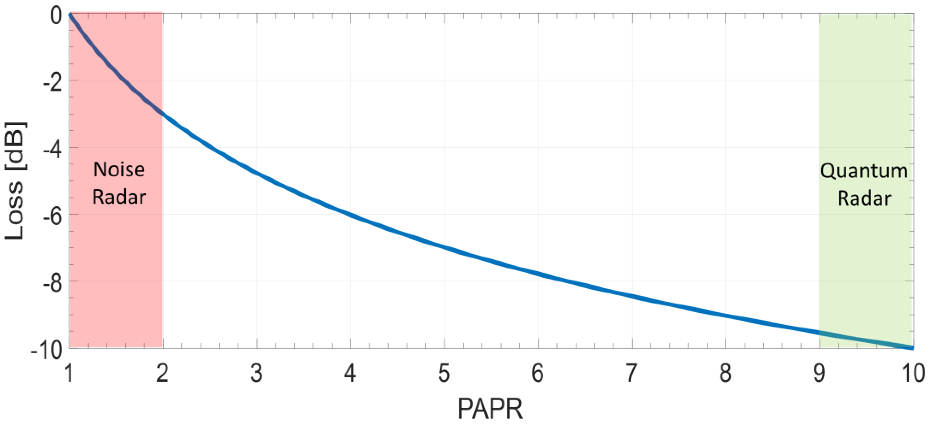
In [20,23,24,44], it is claimed that the above-described QTMS radar operation is similar to that of a noise radar (NR) [45,46]. In reality, NR and QR are quite different. NR may transmit every kind of pseudorandom signal: with a constant modulus (phase-only code) or with a suited “tailoring” of the signal [32], i.e., allowing a very low peak sidelobe level ( P S L ) below the main lobe and an acceptable suited peak to average power ratio ( P A P R ), e.g., as low as 1.5 (corresponding to a 1.76   d B loss, see Figure 2), and more generally with non-Gaussian statistics (pink area).
In QR, the signal is “naturally” random and not modifiable, and hence the resulting P A P R (around 9–10: see the green area) yields a loss close to −10 dB. The difference between NR and QR of about 7–8 dB, shown in Figure 2, largely compensates for the alleged maximum QR advantage of 6   d B .
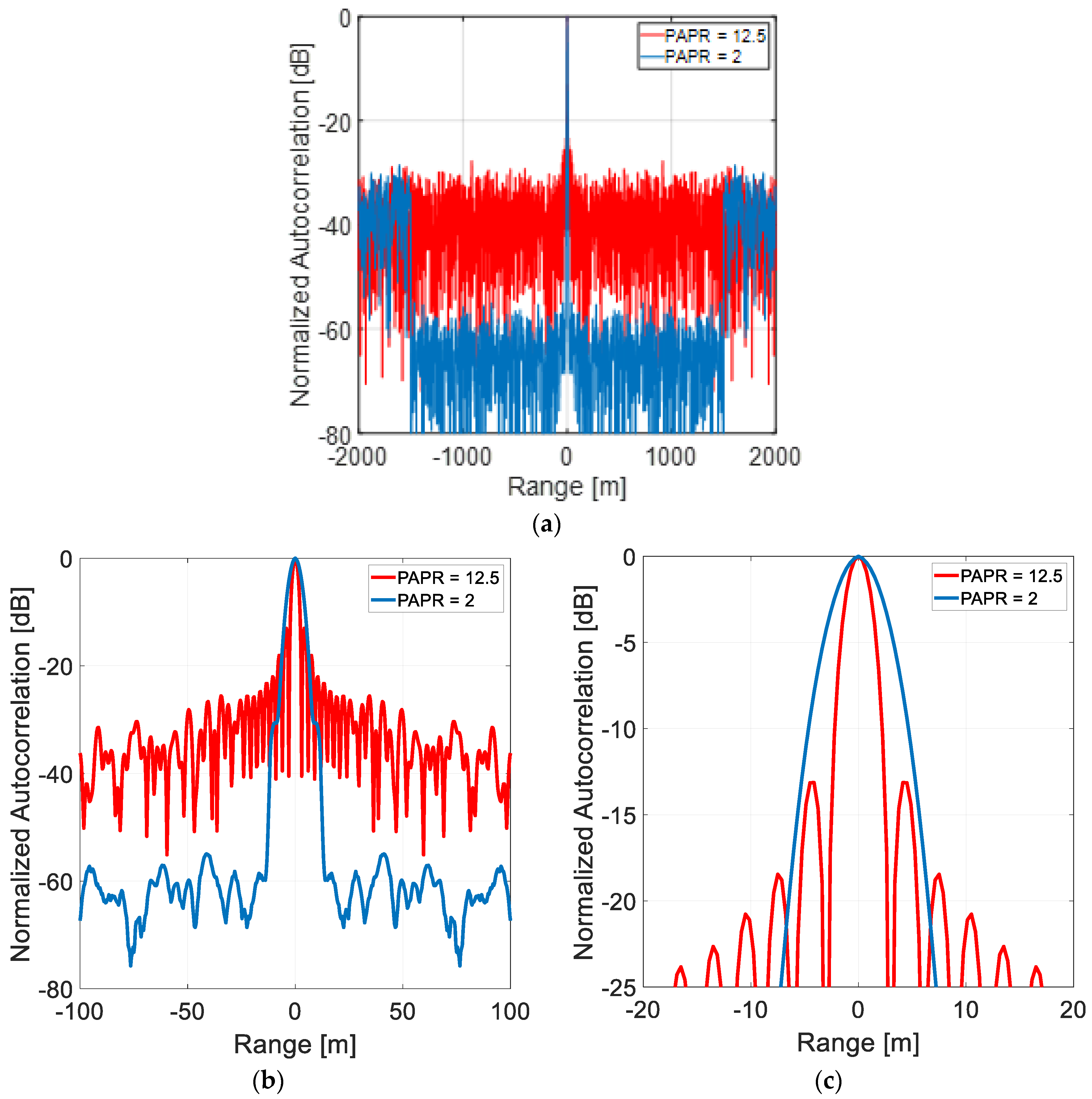
An example of the superior radar data quality of NR when using “tailored” pseudorandom waveforms with respect to the “naturally Gaussian” QR waveforms follows. The following is assumed for both NR and QR signals: bandwidth B = 50 MHz, duration T = 100   μ s (i.e., M = B T = 5000 ), and noise and interference absent, assuming that the NR waveform has been tailored (details are provided in [32]) to place the sidelobes of its autocorrelation function below 60 dB ( P S L 60 dB) in the delay region of ± 10   μ s (corresponding to ± 1500   m ). The output of the compression (matched) filter is shown for NR and QR in Figure 3.
At the expense of a modest sensitivity loss (2 dB for a PAPR of 1.6), the NR has better range resolution of multiple near targets, a performance impossible to obtain in the QR realm, where the generated signal is Gaussian and cannot be tailored.
In [20], a comparison was performed with a particular (and quite “artificial”) classical radar demonstrator, named two-mode noise (TMN) radar, and implemented as close as possible to the QTMS radar demonstrator (including the cryostat refrigerator at a few m K ), but with the pair of non-entangled signals generated by mixing Gaussian noise with a sinusoidal carrier. The authors of [20] warned that similarity between a NR and the TMN radar demonstrator lies only in the fact that both NR and TMN transmit random signals. In reality, it is very important to remark that the randomness in the TMN radar (and, more generally, in QR) is unavoidable and uncontrollable, due to the quantum mechanical signal-generating process. Conversely, in modern NR, the preferred solution is fully digital using pseudorandom number (PRN) generators (see, for instance, [46,47,48]).

5. Radar Range for Quantum Radar

5.1. General Remarks: Some Simple Photon Number Analysis

The quantum radar operation is based on target detection by idler-signal photons’ correlation, as previously explained. On the other hand, detection of a radar target depends on the energy transmitted on it and by its back-scattering, quantified by the radar cross-section (RCS). Let us consider a simple, cheap (about USD 7000) X-band marine radar, such as HALO 6 (https://panbo.com/how-simrad-halo-works-12-radars-in-one/, accessed on 4 July 2024). It is a solid-state set that transmits at frequencies around 9.4   G H z , 2.5   m J (i.e., a lower energy than a legacy marine radar with a 6   k W magnetron and 1   µ s pulse, which transmits 6   m J ). Its range is as follows:
  • 5.32 km for a target with a RCS of 1 m2.
  • 8.8 km for a small vessel with a corner reflector (RCS = 7.5 m2).
The energy of a single microwave photon at 9.4   G H z is 6.23 · 10 24   J ; hence, in order to reach the requested 2.5   m J , the radar will send to the target a number of photons of about N s = 4 · 10 20 , which with a number of background photons (see Figure 4 of Section 5) and an attenuation (see Figure 5 of Section 5) of the order of 160   d B , of the order of 10 3 , still leaves some SNR margin for target detection. This N s value is consistent, for example, with an illumination time of T = 100   µ s , a bandwidth of B = 100   M H z , and a “number of modes”, B T , of 10 4 . However, as a quantum radar is such only when N s < 1 , a corresponding QR should operate (assuming N s = 0.4 ) with a 10 21 times larger B T product, which for the same bandwidth corresponds to T = 10 17   s ; that is, over three billion years.
Determining the maximum operational range of a radar set seems feasible with a simple computation of the radar equation, historically standardized by the classical report (and the ensuing book) on pulse radar range by L. V. Blake [49]. However, the task is more difficult when considering the many factors affecting the computation (target fluctuations, equipment losses, multipath, internal and external disturbances, and more), so much so that the real operational radar range is sometimes as short as half of the computed range, i.e., detection losses whose sum is as large as 12   d B may be neglected, as mentioned by M.I. Skolnik [50].
For QR, the maximum range is an even more complex matter, related to the statistical description of the involved photons by the Bose–Einstein equation. The latter, see Equation (1), yields the average number of photons per mode, N B (where the subscript B stands for background), versus the frequency, at a system temperature, T s (in Kelvin):
N B = 1 e x p h f K B T s 1
where K B = 1.38065 · 10 23   J / K is the Boltzmann’s constant and h = 6.62607 · 10 34   J · s is the Planck’s constant. At radio and microwave frequencies and at room temperature, h f K B T s ; hence, considering the approximation of the exponential at the first order, Equation (1) becomes:
N B K B T s h f
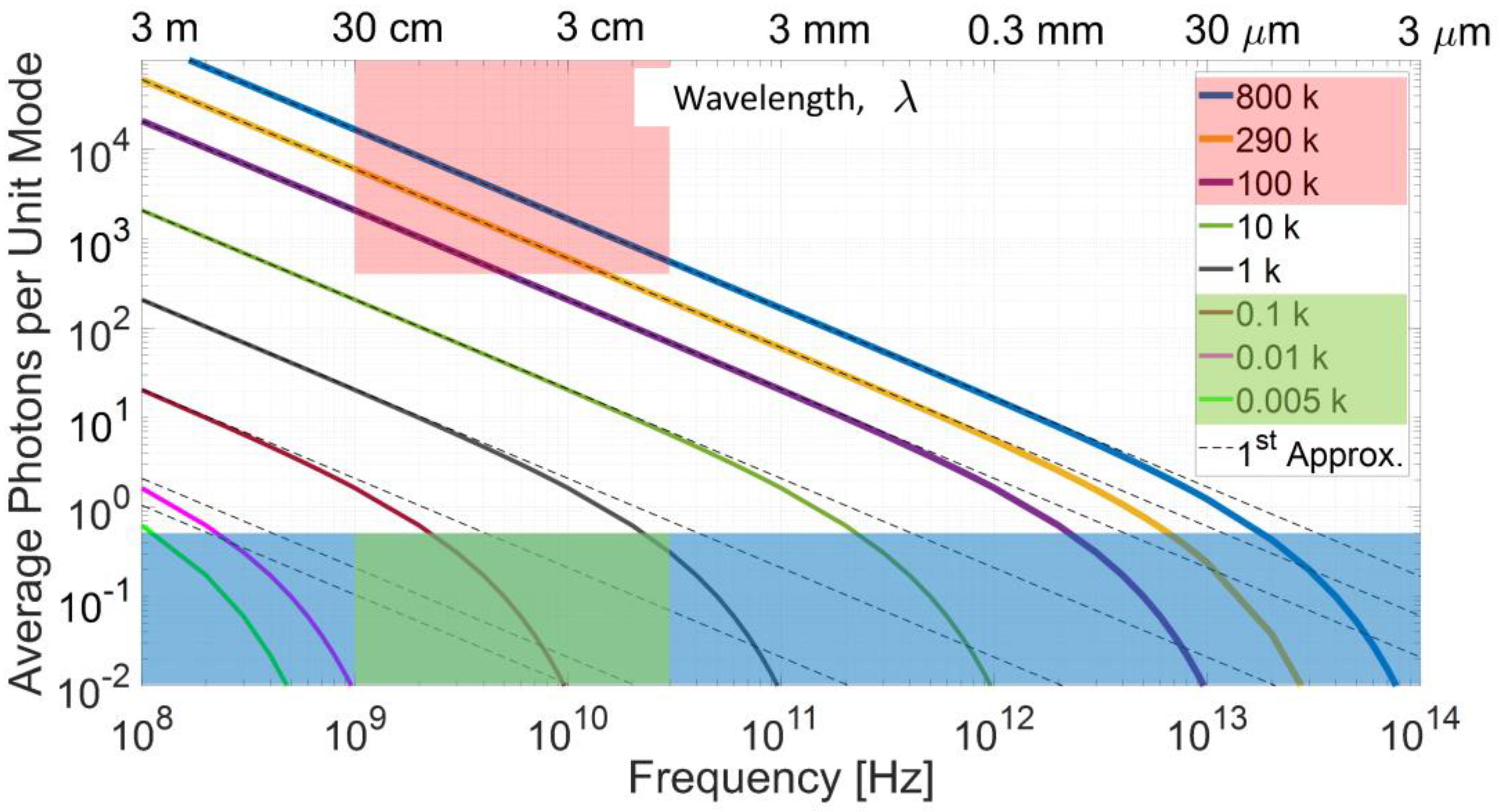
Figure 4 shows Equation (1) varying f from 0.1   G H z to 100   T H z . The blue area ( N s < 0.5 ) is the optimal for quantum operation (the QR system has the optimum quantum advantage for an average photon number 1 and loses the advantage nearly completely for a number of photons greater than about five). Dashed lines represent Equation (2), i.e., the linear approximation.
The green subset of the blue area represents the average generated photons for a microwave ( 1   G H z < f < 30   G H z ) QR, at temperatures below 1   K . The upper pink area represents the much more numerous background photons, Equation (2), from a favorable case of T s = 100   K to a more frequent radar situation of T s = 290   K . A worst case of T s = 800   K is also shown. For an X-band radar ( λ = 3   c m ) at room temperature, N B is of the order of 10 3 , and is less than the unit only at T s well below 1   K .
From the formula for the noise power in a bandwidth B , i.e., P r n = K B T s B , the “background noise” power with N B photons can be written, using Equation (2), as:
P r n N B h f B
The literature on the range performance of a QR often simplifies the disturbance as P r n of Equation (3), while radar engineers know very well that the radar disturbance is something more complex. It includes unwanted echoes, propagation effects (with related attenuation), antenna noise, radiofrequency connections to the receiver, and finally, the first active reception stages [49,50,51].
In [52], we read (in the text, = h 2 π , W is the bandwidth, B , and T is the system temperature, T s ): “In QI radar, the noise power of the receiver can be expressed as P r n = ω W e x p ( ω / K B T ) 1 […]. In practice, it is difficult to accurately calculate the noise temperature, which is related to factors such as antenna geometry, beam direction, solar activity, and signal wavelength, etc. Therefore, in the subsequent analysis, we define the equivalent noise temperature of 3–300 K, which can represent the majority of radar operating scenarios”.
The lower value above is quite optimistic: the system noise temperature, T s , of a radar set is typically close to (or above) 250–300 K. In fact, the system noise temperature, T s [51], referenced to the output of the radar antenna, is the sum of three contributions: by the antenna ( T a ), by the radiofrequency ( T R F ) connections of the antenna with the receiver (including the duplexer and the rotary joint—if any), and finally, by the receiver itself, whose main element is normally a low noise amplifier, LNA ( T L N A ). Hence, it results in:
T s = T a + T R F + T L N A
With:
  • Ta resulting from the external noise sources, including: the CMB (cosmic microwave background), the sun, the stars, the atmosphere, the land, and sea surfaces. In the absence of any radio stars, the CMB assumes a minimum level around 5 K (see “Figure 8.19”, page 526, chapter on Propagation of Radar Waves, in [50]), whose 2.7 K blackbody term, uniform in all directions, is due to the radiation left over from the hot big-bang. Hence, Ta is a highly variable quantity. Common graphs [49] supply this contribution versus the operating frequency for a “standard environment” and for different values of the pointing angle, θ, of the antenna with respect to the vertical. For example, in the X-band (9 GHz), Ta has a maximum value of about 100 K when pointing toward the horizon (θ = 90 degrees) and a minimum value of about 10 K in the unrealistic case of zenith pointing (θ = 0). To set exemplary values, assuming θ = 30 degrees, we have Ta = 30 K, but for a surface movements radar (SMR), whose antenna points down, Ta is close to the land temperature.
  • TRF = (LRF − 1)·T0, where T0 is the reference temperature of 290 K (according to the IEEE standard) or, if known, the physical temperature of the previously mentioned RF connections, and LRF is their attenuation (i.e., the loss). An exemplary value (for a 0.5 dB loss) is TRF = 35 K.
  • TLNA = (F − 1)·LRF·T0, where F is the noise figure of the amplifier. For an exemplary F = 1 dB and the above 0.5 dB loss, TLNA = 190 K.
The sum of all contributions yields a typical value of T s = 255   K (but over twice for a SMR).
Basic and contrasting facts dominate the power budget, and hence the computation of the QR range. They are as follows:
(a)
The energy in a single photon at microwave frequencies is extremely small when compared to that of a conventional radar (CR) pulse; therefore, with the number of transmission modes, M , defined by operational constraints, one could try to increase the number, N s , of average signal photons per mode. This increase brings back the radar system to the classical operation. With a number of photons per mode, say 0.01 , optimal for quantum advantage, the transmitted energy per microwave radar pulse (i.e., per mode) is 16 to 20 orders of magnitude below what is required for target detection. Moreover, according to quantum mechanics, the amplification of the radar signal generates noise, which would nullify the quantum advantage [42].
(b)
Theoretically, a quantum illumination system will provide a factor-of-four ( 6   d B ) improvement in the error probability exponent (neglecting the fact that radar detection is not evaluated in terms of error probability [28]) over its classical counterpart of the same transmitted energy [42,44] (note that the practical QR implementations limit this advantage to lower figures: order of 1 to 3   d B only [42,53]). However, a 6   d B improvement can be obtained, remaining in the conventional radar technology, increasing the dimensions of the transmit/receive antenna (antennas); for example, in the monostatic case (a single Tx/Rx antenna), changing a 1.2   m dish into a 1.7   m dish.
(c)
The benefit of QR over CR is significant for very few average photons per mode ( < 1 ) and disappears for more than a few transmitted photons per mode.
(d)
The energy of a photon is proportional to its frequency, calling for QR operating, for example, in the millimeter-wave or terahertz bands, where, unfortunately, the atmospheric phenomena prevent long-range operation.
(e)
The increase in the number of modes, M , for a (necessarily limited) available signal bandwidth, B , would generate an increase in the pulse duration (see Section 5.2). Values of T above some threshold (order of a few milliseconds to hundreds of milliseconds, depending on the type and dynamics of the particular target) would render the system prone to the effects of target scintillation and Doppler frequency, destroying the correlation with the stored replica, hence nullifying the quantum advantage.
Summing up, we quote from the Introduction of [54]: “… while realizable experimentally, useful application of microwave quantum radar protocols to any conventional setting is unrealistic because of fundamental restrictions on power levels”.

5.2. Exemplary Range Computations for QR

Some computations for a representative QR are shown in the following to sustain the previous discussion. The related main parameters are:
f 0 : operating (central) frequency,
λ = c / f 0 : wavelength,
B : operation bandwidth, i.e., f 0 B 2 f f 0 + B 2 ,
T : signal duration (less than or equal to the dwell time),
M = B · T : number of modes,
σ : radar cross-section (RCS) of the target,
G : antenna gain (the same for Tx and Rx),
T s : system noise temperature,
S N R : signal-to-noise ratio,
L : total loss ( L < 1 ) ,
a R : free-space two-way attenuation for a target at a distance R ,
η Q : quantum advantage.
First, the free-space two-way attenuation (designated κ in the QR/QI literature) is:
a R = G 2 λ 2 4 π 3 R 4 σ
The attenuation, a R , is shown in Figure 5 at the X-band ( f 0 = 9.37   G H z , = 0.032   m ) with a 1   m 2 RCS. At a distance of 1   k m , the attenuation is 123   d B for G = 30   d B .
The received power from a target at a distance R is:
P r s = M · N s h f 0 B · η Q · a R
where N s is the average number of photons per mode and η Q is the quantum advantage (alleged to range from 0 to 6   d B ). From Equation (2), the background noise power in a bandwidth, B , around f 0 is equal to the classical relationship:
P r n = K B T s B N B h f 0 B
Hence, using Equations (6) and (7), the signal-to-noise ratio is:
S N R = P r s P r n = M N s · η Q N B · a R = B · T N s · η Q N B · a R
To achieve a positive (in d B ) S N R at range, R , the quantum radar will operate with a time duration, as follows:
T N B N s · η Q · 1 B · a R
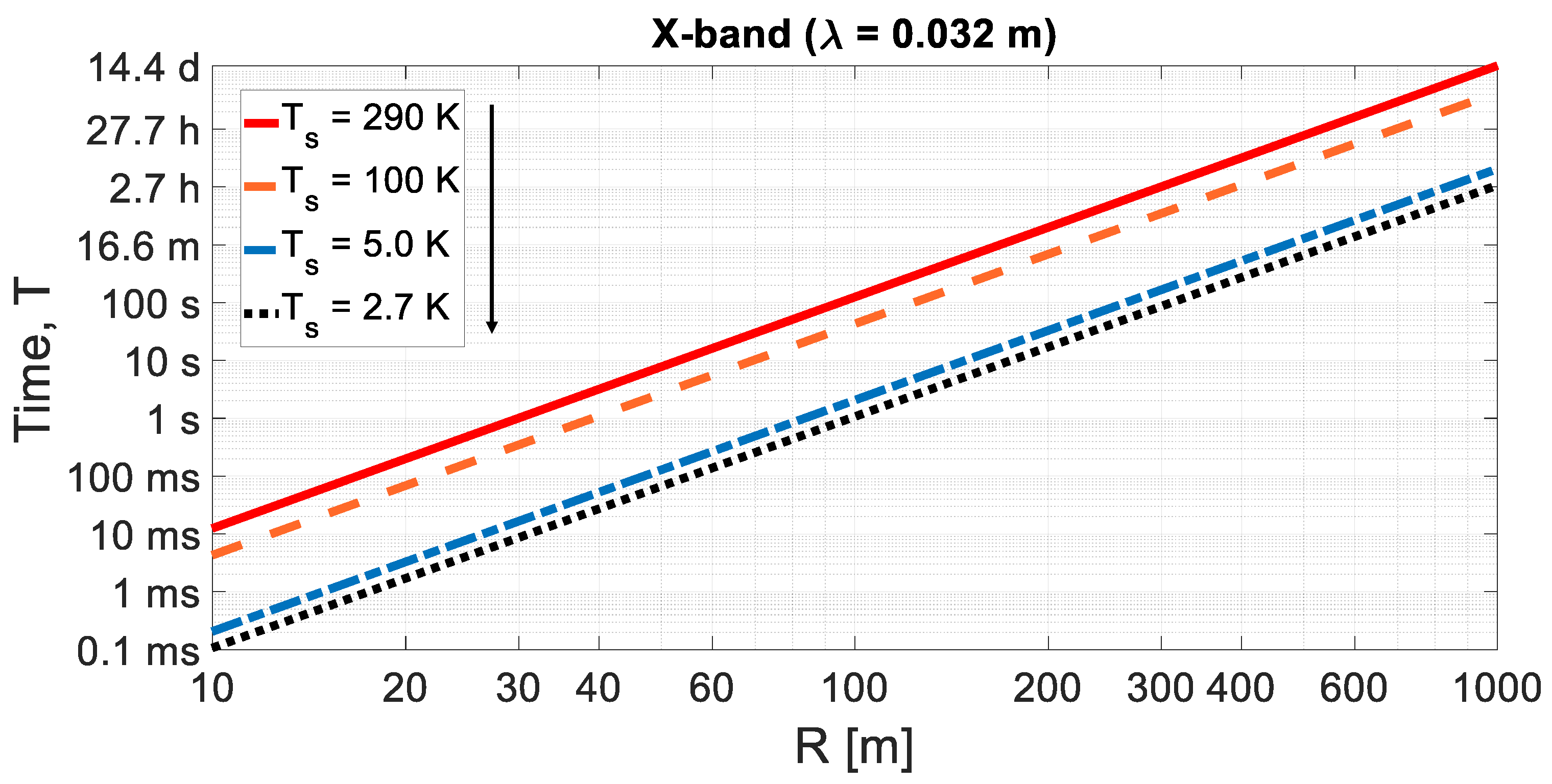
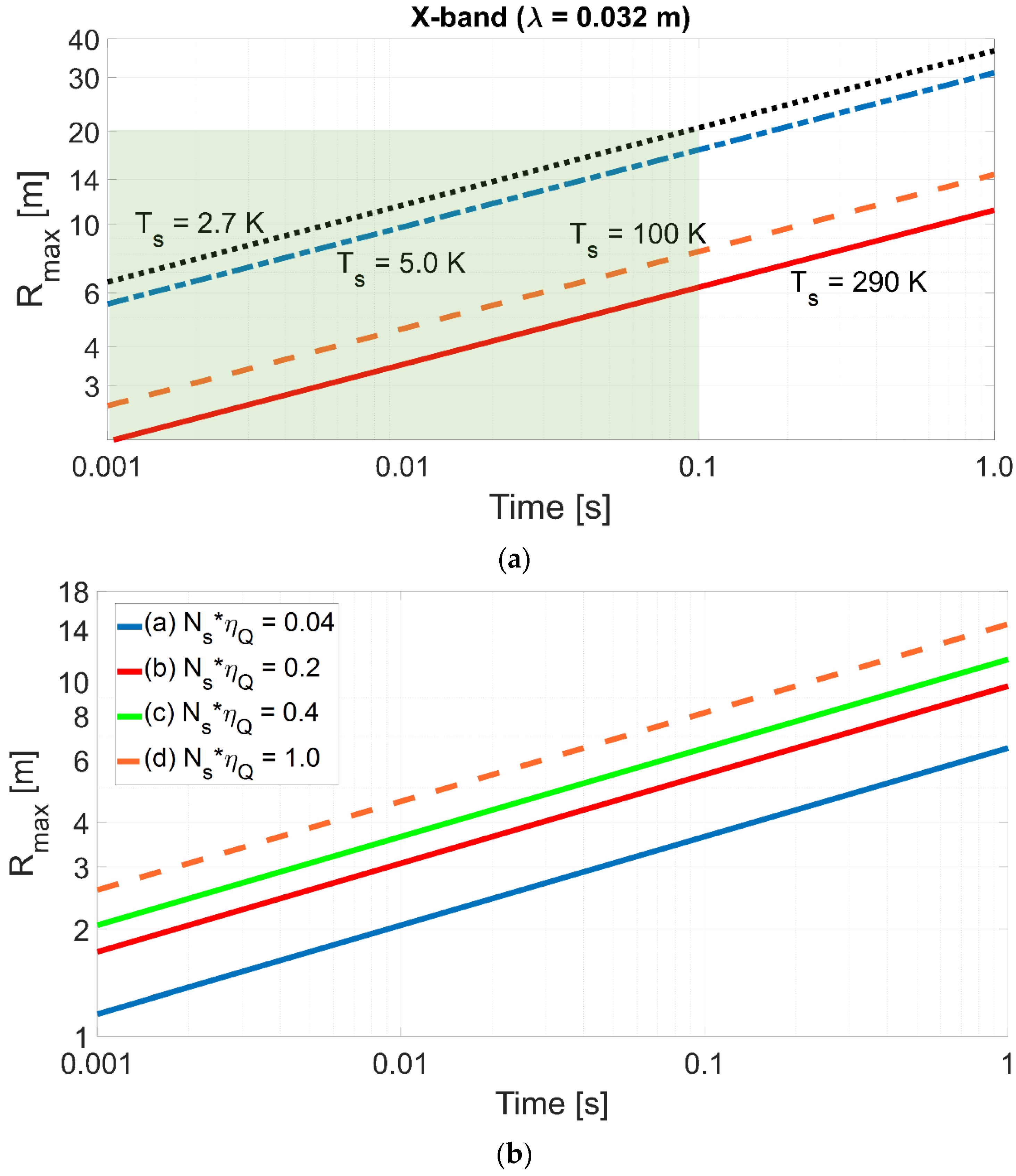
At the X-band ( f 0 = 9.37   G H z ), assuming a bandwidth B = 1   G H z (about 10 % of f 0 ), setting N s · η Q = 1 for the sake of simplicity (e.g., we assume N s = 0.25 with η Q = 6   d B ), σ = 1   m 2 , R = 1   k m , and an antenna gain (the same in Tx and Rx) of G = 30   d B , with T s = 290   K , it results in T 346   h , which appears absurd. With a target much closer, i.e., at R = 10   m , the S N R is 1 0 8 times greater than at 1   k m , and an operation with the same B T should permit T to be in the order of ten milliseconds. From Equation (9), we can reduce the time T , increasing B . However, the use of the electromagnetic spectrum by radar is regulated by the ITU (an ONU agency); anyway, for both technical and regulatory reasons, the general radar bandwidth allocation does not exceed 10 % . Therefore, the theoretical possibility of radar transmissions in an ultra-wide band is limited in principle to indoor, very short-range applications [55]. More exemplary time values are shown in Figure 6 for T s = 100   K , 5.0   K , and 2.7   K .
Note that in the following Figure 6, Figure 7, Figure 8, Figure 9 and Figure 10, the attenuation due to propagation in the atmosphere (that depends on various factors, including the operating frequency, the elevation beam pointing, and more) has been ignored to perform a simple and readable comparison between CR (or NR) and QR.
From Equations (6) and (8), the QR maximum range ( R m a x ) can be evaluated as:
R m a x = G 2 λ 2 L · σ 4 π 3 S N R m i n · N s · η Q N B B · T 1 4
where L is the total loss, neglecting the attenuation of the medium. Setting: L = 4   d B , S N R m i n = 13.2   d B [56], σ = 1   m 2 , N s · η Q = 1 , λ = 0.032   m , and B = 1   G H z , and varying the time duration, T , from 1   m s to 0.1   s (i.e., M from 10 6 to 10 8 ), Figure 7a shows the maximum range versus the time duration. Figure 7b shows the contribution of the quantum advantage.
The above evaluations, shown in Figure 7a, used the simplified and conservative condition N s · η Q = 1 to define the order of magnitude of the QR range. More precise evaluations are shown in Figure 7b for T s = 100     K and the following cases and values:
N s η Q N s · η Q
(a) QR—theoretical η Q —low N s 0.014 (6 dB)0.04
(b) QR—potential η Q 0.12 (3 dB)0.2
(c) QR—theoretical η Q 0.14 (6 dB)0.4
(d) QR—optimistic η Q —high N s 0.661.5 (1.76 dB)1.0
For 100   K < T s < 290   K , R m a x is less than 10   m . Considering the CMB contribution around 5   K or 2.7   K , the maximum range is less than 20   m . Ranges greater than about ten or twenty meters can only be achieved when the whole radar set, including the antenna (and the external surfaces within its main lobe), is cooled at cryogenic temperatures, which is not compatible with any use outside a specific laboratory.
In order to stay independent of the radar operating wavelength, λ (eliminating the λ 2 term in the radar equation), in [12], the authors take, as a standard reference target, a trihedral triangular corner reflector (TCR) with side a , i.e., with RCS σ = 4 π a 4 3 λ 2 , and the considered target is an object with size A > a . Note that at the typical X-band radar wavelength of 3.2 cm, σ = 1   m 2 for a relatively small TCR with a = 0.125   m , while for a = 1   m , the resulting X-band RCS is quite large, i.e., 4000   m 2 . From “Figure 6” of [12], and for an object size of 1 m (corresponding to 36   d B m 2 of RCS for the TRC in the X-band), in the “feasible scenario” realm of [12], the radar range results between 10   m and 40   m , i.e., of the same order as the evaluations in this work, whose overall results are confirmed.
Note that the situation improves as the frequency increases ( N B quickly decreases, see Figure 4), but above circa 8   G H z , the attenuation by rain becomes a very critical factor and, with increasing frequency above 35   G H z , the attenuation by the atmosphere also becomes critical, preventing QR from any operational “outdoor”, either civilian or military, radar application at medium–large distances.
In this work, aiming to perform CR and QR comparisons, atmospheric effects (including hydrometeors) have been neglected, as they act equally on CR and QR.
In general, the order of magnitude of the maximum range is similar to the one shown in “Figures 2a and 3a” of [52], evaluated for T s = 300   K   a n d   3   K . Note that the advantage of QR over CR, as shown in these figures, is negligible when N s > 1 , and that for N s < 1 , the QR range does not exceed a few tens of meters at the X-band. Different evaluations (at the X-band, again) are shown in [53] (see “Figure 3” of [53]), where the system noise temperature, T s , is set to 10   m K (Table II of [53]), which is only possible when the radar and the environment are closed in a cryogenic generator and shielded from the 2.7   K CMB. However, this situation is not compatible with any practical use.
Similar detection performances for a millimeter-wave QR at 95   G H z (W-band) are shown in Figure 8 for the sake of completeness.
These evaluations show that the “long-distance detection” of QR in the title of [22] will not apply to real-world situations. Of course, the same applies to the alleged detection of stealth targets, see [16,18]. Stealth targets call for a high-power illumination, which contrasts with the QR nature itself, and the radar cross-section of a target (either stealthy or not) does not change when QR is used, as elegantly shown in [10], as the path of each photon to the target is not well defined because of the position uncertainty, and this causes some quantum interference, which exactly replicates, in the far-field limit where the radar cross-section is defined, the classical scattering behavior of electromagnetic waves.

5.3. Maximum Range: QR and NR Comparison

In some papers [28,53,57,58], quantum radar is proposed because of its low probability of intercept (LPI) features due to the intrinsic randomness of its emission. Similar characteristics belong to noise radar [45,46,47,48]. Hence, it is interesting to compare the performance of NR and QR in equivalent system configurations.
A simple comparison figure is the ratio of maximum ranges: R N R R Q R . For quantum radar, R Q R is computed by Equation (10), while for the continuous-emission noise radar, by [48], we have:
R N R = P T G 2 λ 2 L · G I N T · σ 4 π 3 S N R m i n K B T s B 1 4
with the usual meaning of symbols, where G I N T is the coherent integration gain, equal to the product B · T I N T , and T I N T is the coherent integration time ( T in QR), equal to or less than the dwell time. Hence, the desired ratio is:
R N R R Q R = P T K B T s B · N B N s · η Q 1 4
Assuming N s · η Q 1 and taking into account that the antenna and the receiving parts operate close to room temperature, i.e., T s   1   K and N B K B T s h f (see also Figure 4), Equation (12) becomes:
R N R R Q R = P T h f · 1 B 1 4 = E T h f · 1 M 1 4 = N T M 1 4
where E T ( = P T T ) is the energy coherently transmitted on the target, M = B · T is the number of modes, and N T is the related number of photons transmitted by the NR: N T = P T · T h f .
For P T = 100   m W , f = 10   G H z , it results that N T = 1.51 · 10 22 · T . To obtain R N R = R Q R , one has to set M = N T , i.e., an unthinkable bandwidth, B = 1.51 · 10 13   G H z , which could only be achieved by operating at unrealistic carrier frequencies above 10 23   H z .
A similar evaluation is presented in [53], where, however, cooling of both CR and QR sets at 10   m K is considered, and the ratio between “Equation (12)” and “Equation (14)” of [53] leads to a conventional radar/quantum radar range ratio equal to: R C R R Q R = 1 M 1 4 (note that in [53], the number of modes is m in place of M ), which is rather in agreement with the ratio of red and blue curves of its “Figure 3” (referring to the X-band and to m = 6 , which for the bandwidth B = 2   G H z corresponds to an unrealistic illumination time of a mere 3   n s ) but not with the evaluations shown in this chapter. Likely, there are errors in the computations (called “simulations”) of [53], and the pulse compression gain was likely not taken into account. However, it is necessary to mention the recent paper [58] of the same authors, where the compression gain of CR was considered, and it was confirmed that the conditions N s 1 , N B 1 and M 1 maximize the advantage of quantum illumination but, unavoidably, lead to very short radar ranges. The conclusions of [58] include: “... although QI shows its advantages, this advantage is limited to the case of very weak transmitted signal power, so it may be a challenge for applying QI to radar remote detection”.
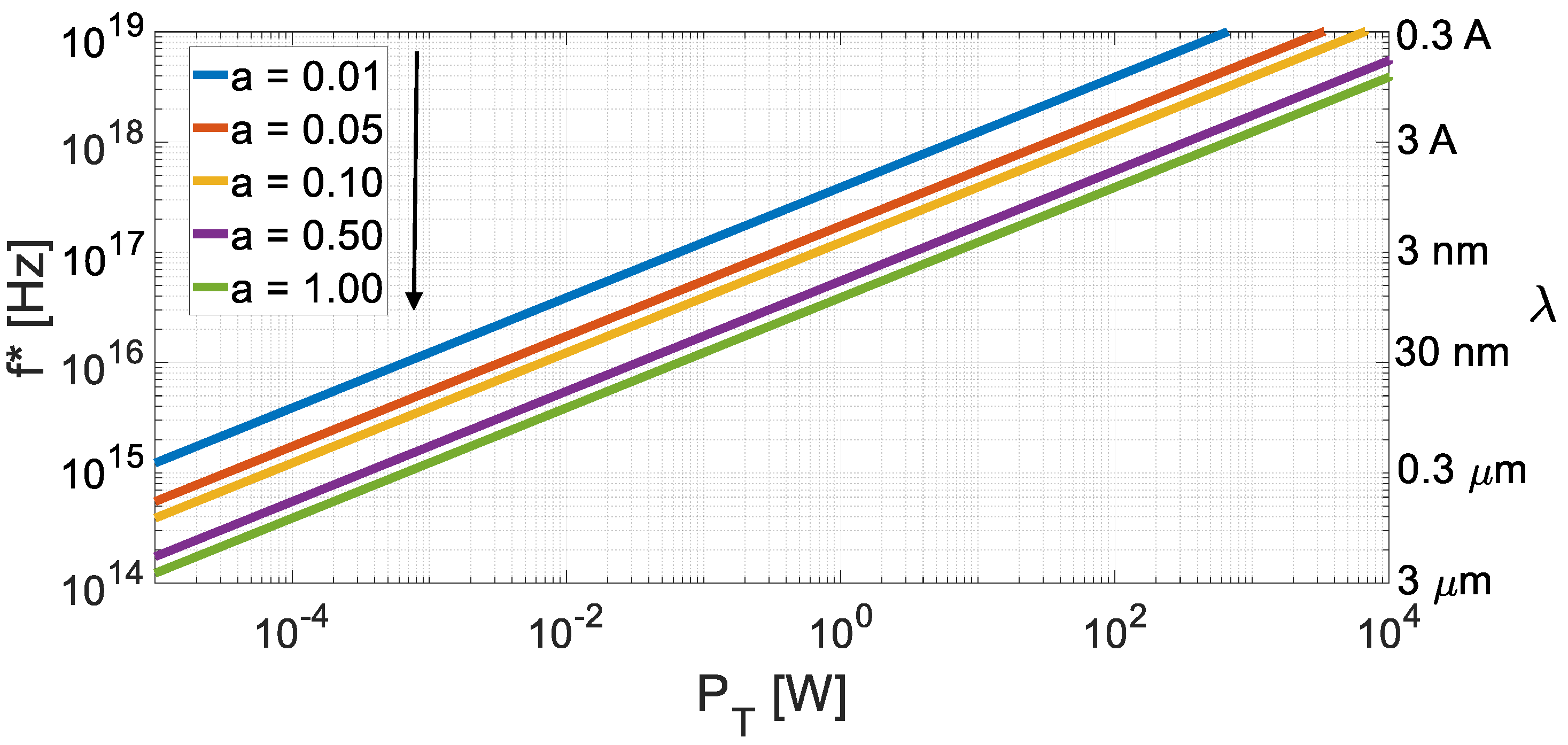
From Equation (13), one can easily compute the frequency, f * , making R C R = R Q R , i.e., f * denotes the frequency value that makes the maximum range of the QR equal to the NR. Posing B = a · f , with a < 1 (fractional bandwidth), it results that:
f * = P T h · a
Figure 9 shows Equation (14), confirming that quantum sensing tends to become useful (i.e., with the same maximum range of a NR) at very high frequencies (e.g., in the optical and infrared realms, and above) and at very low power levels.
For an analysis of QR operation above millimeter-wave frequencies, the interested reader may see [52]. The pertaining computation of the QR range is 800   m at λ = 1   m m and 4500   m at λ = 0.1   m m . However, in [52], atmospheric attenuation is not taken into account (unlike in [59]).
Figure 10 shows a comparison between the maximum ranges of QR and NR at similar operating conditions. For the quantum radar, the maximum range, Equation (10), is in the order of meters, while a 100   m W noise radar improves the range, Equation (11), to the order of tens of kilometers (the system temperature is set to the realistic values of 100 and 290   K , and to the bad value of 800   K for comparison).

6. Final Discussion

All the evaluations in this work refer to the most common radar applications aimed to detect and locate “point” targets, such as aircraft. Of course, other radar applications, such as imaging and tomography, have their own specific power budget, whose quantitative analysis, in the QR case, was outside the aim of this work.
The use of QR has been recently proposed [40] for biomedical sensing, i.e., a short-range (order of meters or less) case. Short-range radars were introduced for healthcare applications of detecting human vital signs in 1975. Heart rate measurements have been successfully measured at a 1   m distance using sub-micro-watt power levels [60] and FMCW radar technology.
Non-invasive microwave techniques for contact and remote sensing of respiratory and circulatory movements have been developed with the average power density of radiated energy ranging from 1   µ W to 1   m W per square c m , i.e., much lower than the ones due to the cellular phones used by patients and sanitary personnel. Some systems are capable of measuring the heart rate and breathing rate at distances of 30   m , or behind thick layers of non-conductive walls.
Hence, in healthcare applications, the QR is not a useful option, because:
(i)
the SWaP limitations are obviously important (contrary to what is written in [40]),
(ii)
the short distances imply very low transmitted microwave power levels, for which a 6 dB advantage is immaterial.
Among these particular applications, microwave tomography should be noticed [61,62,63,64]. As another example, in the conclusions of [12], the QI (or QR) approach is prospectively mentioned to be useful for studies of cell biology, whenever the radiated power on single cell should be constrained. However, the requested broadband operation hardly copes with the microwave (or radiofrequency) QI/QR technology because of the needed “phase matching” conditions [42], and the need for a few dBs of “quantum advantage” in those applications is questionable.
An increase of the theoretical quantum advantage of 6 dBs has been proposed in [65], where hyperentangled photons are defined as simultaneously entangled in multiple degrees of freedom. In [65], it is proposed to use pairs of photons hyperentangled in two degrees of freedom, namely, polarization and frequency–time, to achieve a 12   d B performance improvement in the error probability exponent over the best-known quantum illumination procedure. The performance is theoretically evaluated for the particular case of N s = 0.01 , N B = 25 , and two-way attenuation, κ = 0.01 . The proposal refers to optical (Lidar) technology, not to microwave radar, and even in the (undemonstrated) case of hyperentangled QR attaining the maximum quantum gain of 12   d B , the maximum radar range values in the sentence, “radar range results between 10   m and 40   m ”, will change into “radar range results between 20   m and 80   m ”, which is substantially equivalent from any operational viewpoint.

7. Conclusions

The intrinsic range limitations of QR were analyzed in this study. The quantitative analysis was not extended to range measurement, which is a difficult issue in quantum radar, adding complexity to a complicated equipment.
Other relevant considerations, such as technical feasibility, operational problems, and last but not least, cost, are found in [41,42]. A good synthesis on the operational problems of QR and its readiness is presented in [66]. The conclusion of [66] includes the following passage: “Ultimately, one should not dwell on the black-and-white ‘what is better’ mentality, but rather pursue this technology with the mind-set of intellectual curiosity and ignorance on its most appropriate application”.
This general approach would be acceptable, or even welcome, if applied to basic research. However, radar is an object of applied research, in which, for ethical reasons, it seems not fair to promise impossible results to public financing bodies, especially when the impossibility may be easily demonstrated. In fact, there is no reason why a quantum radar, irrespective of the used protocol, should perform better than a conventional (or noise) radar. Therefore, the rationale of some claims found in [16,17,18,19] regarding stealth targets and long-distance detection remains unmotivated.
We conclude that:
  • With a strong constraint on the transmitted power, a limited quantum advantage is alleged in some literature.
  • We have shown (Section 4) that, differently from classical radar and NR, QR signals cannot be “tailored” and are inherently random, with Gaussian distribution, thus causing a relatively large P S L , in the order of 1 / M . Important for the radar range point of view, QR signals have a poor peak-to-average power ratio ( P A P R ), whose estimated value depends on the chosen truncation point for the Gaussian law and is in the order of ten or twelve. The related loss, around ten or eleven decibels, is larger than all the values of “quantum advantage” presented in the literature, and cancels “ad abundantiam” any quantum advantage in any comparison with the noise radar technology and with any classical radar using “phase only” (constant amplitude) signal coding.
  • If a low-powered signal of a quantum noise radar is amplified, then a classical noise radar results, which outperforms the quantum radar.
  • Quantum radars are more difficult to achieve than what some early papers (and one book) were claiming, and the work with signal photons in the microwave (or mm-wave) systems seems not a fruitful idea.
  • The alleged military advantage of a quantum radar due to its covertness is practically immaterial due to its extremely short operating range.
  • The QI/QR concept might be useful for future quantum sensors in ultraviolet, X-ray, and Gamma domains. The related challenges consist of the lack of methods for efficient coherent signal processing at these frequencies, while conversion down to the frequencies below, say, 5 GHz, where ADCs are readily available, is also problematic [55]. Moreover, at those frequencies, the attenuation propagation and the target’s back-scattering are much different than at microwave frequencies.
Conclusions similar to the ones of this work are appearing in widely distributed journals, such as Science [67], from which we report the following: “Even if experimenters can overcome the technical hurdles, quantum radar would still suffer from a fatal weakness, researchers say. The entangled pulses of microwaves provide an advantage only when the broadcast pulses are extremely faint. The extra quantum correlations fade from prominence if pulses contain significantly more than one photon—which is overwhelmingly the case in real radar. ‘If you crank up the power, you won’t see any difference between the quantum and the classical’, Barzanjeh says. And cranking up the power is a much easier way to improve the sensitivity”.
Again in [67], it is noticed that it is difficult to establish a useful and practical microwave application of quantum sensing, even with the full advantage by an entangled source (e.g., the promised 6   d B advantage) when a simpler classical system will perform better with higher power output and a cheaper and simpler setup.
The explanation in [13] deserves a final quote, which follows:
“… given that fundamental processes in the universe are quantum, … the classical mechanics works because the macroscopic world has so many particles that the quantum states decohere and quantum mechanics becomes classic” […] “the quantum-to-classical transition can be understood as a consequence of the mechanism of decoherence. Pure states remain pure only in closed systems”.
Summing up, the study of the “short, strange life of quantum radar” (from the title of [67]) tells us, once again, that while it is generally difficult to find the correct solution for a given problem, it may be even harder to find the correct problem for a given solution.

Author Contributions

G.G. defined the main content, including the analysis of the state-of-the-art of the quantum radar, and the overall organization of the paper. G.P. developed the numerical evaluations of the range radar and performed writing—original draft preparation. All authors have read and agreed to the published version of the manuscript.

Funding

This research received no external funding.

Conflicts of Interest

The authors declare no conflicts of interest.

List of Acronyms

CMBCosmic microwave background
CNITNational Inter-University Consortium for Telecommunications
CRClassical radar—conventional radar
FMCWFrequency modulated continuous wave
IEEEInstitute of Electrical and Electronics Engineers
INRIMIstituto Nazionale di Ricerca Metrologica (National Metrology Institute)
ITUInternational Telecommunication Unit (a United Nations Agency)
JPAJosephson Parametric Amplifier
JTWPAJosephson Traveling Wave Parametric Amplifier
NRNoise radar
PAPRPeak-to-average power ratio
PRNPseudorandom number
PSLPeak sidelobe level
QIQuantum illumination
QRQuantum radar
QTMSQuantum two-mode squeezed
RCSRadar cross-section
SMRSurface movements radar
SNRSignal-to-noise ratio
SWaPSize, weight, and power
TMNTwo-mode noise

References

  1. Shapiro, J.H. The Quantum Illumination Story. arXiv 2019. [Google Scholar] [CrossRef]
  2. Hult, T.; Jonsson, P.; Höijer, M. Quantum Radar—The Follow-Up Story. October 2020. Available online: https://www.foi.se/rest-api/report/FOI-R--5014--SE (accessed on 4 July 2024).
  3. Gallego Torromé, R.; Barzanjeh, S. Advances in quantum radar and quantum LiDAR. Prog. Quantum Electron. 2024, 93, 100497. [Google Scholar] [CrossRef]
  4. Lloyd, S. Enhanced sensitivity of photodetection via quantum illumination. Science 2008, 321, 1463–1465. [Google Scholar] [CrossRef] [PubMed]
  5. Allen, E.H.; Karageorgis, M. Radar Systems and Methods Using Entangled Quantum Particles. U.S. Patent N. 7.375.802 B2, 20 May 2008. Available online: https://patents.google.com/patent/US7375802B2/en (accessed on 4 July 2024).
  6. Lanzagorta, M. Quantum Radar, 1st ed.; Springer Nature: Cham, Switzerland, 2011; ISBN 978-3-031-01387-4. [Google Scholar]
  7. Salmanogli, A.; Gokcen, D. Analysis of Quantum Radar Cross-Section by Canonical Quantization Method (Full Quantum Theory). IEEE Access 2020, 8, 205487–205494. [Google Scholar] [CrossRef]
  8. Manoj, M. A Study on Quantum Radar Technology-Developments and Design Consideration for Its Integration. arXiv 2022, arXiv:2205.14000. Available online: https://arxiv.org/pdf/2205.14000.pdf (accessed on 4 July 2024).
  9. Brandsema, M.; Narayanan, R.M.; Lanzagorta, M. Theoretical and computational analysis of the quantum radar cross section for simple geometric targets. In Quantum Information Science; Springer: Berlin/Heidelberg, Germany, 2017. [Google Scholar]
  10. Brandsema, M.; Lanzagorta, M.; Narayanan, R.M. Quantum Electromagnetic Scattering and the Sidelobe Advantage. In Proceedings of the IEEE International Radar Conference, Washington, DC, USA, 28–30 April 2020; pp. 755–760. [Google Scholar] [CrossRef]
  11. Frasca, M.; Farina, A.; Balaji, B. Foreword to the Special Issue on Quantum Radar. IEEE Aerosp. Electron. Syst. Mag. 2020, 35, 4–7. [Google Scholar] [CrossRef]
  12. Bischeltsrieder, F.; Würth, M.; Russer, J.; Peichl, M.; Utschick, W. Engineering Constraints and Application Regimes of Quantum Radar. IEEE Trans. Radar Syst. 2024, 2, 197–214. [Google Scholar] [CrossRef]
  13. Stenger, V.J. The Unconscious Quantum: Metaphysics in Modern Physics and Cosmology; Prometheus Books: New York, NY, USA, 1995. [Google Scholar]
  14. Zettili, N. Quantum Mechanims–Concepts and Applications, 3rd ed.; Wiley: Hoboken, NJ, USA, 2022; ISBN 978-1-118-30789-2. [Google Scholar]
  15. Hill, G. Quantum Radar Is Stealth Radar: Examining the Potential Impact on the Defence Team. 2022. Available online: https://www.cfc.forces.gc.ca/259/290/24/192/Hill.pdf (accessed on 4 July 2024).
  16. Vella, H. Quantum radars: Expose stealth planes. Eng. Technol. 2019, 14, 42–45. [Google Scholar] [CrossRef]
  17. Yung, M.H.; Meng, F.; Zhang, X.M.; Zhao, M.J. One-shot detection limits of quantum illumination with discrete signal. NPJ Quantum Inf. 2020, 6, 75. [Google Scholar] [CrossRef]
  18. Livreri, P.; Enrico, E.; Fasolo, L.; Greco, A.; Rettaroli, A.; Vitali, D.; Farina, A.; Marchetti, C.F.; Giacomin, A.S.D. Microwave Quantum Radar using a Josephson Traveling Wave Parametric Amplifier. In Proceedings of the IEEE Radar Conference, New York, NY, USA, 21–25 March 2022. [Google Scholar] [CrossRef]
  19. INRIM Quantum Radar (TELEDIFE). Available online: https://www.inrim.it/en/research/projects/quantum-radar (accessed on 4 July 2024).
  20. Luong, D.; Chang, C.W.S.; Vadiraj, A.M.; Damini, A.; Wilson, C.M.; Balaji, B. Receiver operating characteristics for a prototype quantum two-mode squeezing radar. IEEE Trans. Aerosp. Electron. Syst. 2020, 56, 2041–2060. [Google Scholar] [CrossRef]
  21. Amat, I.C.; Jiménez, A.G.; Gómez, E.F.; Abdalmalak, K.A.; Fajardo, P.; Cabrero, J.F.; Muñoz, L.E.G. Advantages and Limitations of Quantum Radar. In Proceedings of the 17th European Conference on Antennas and Propagation (EuCAP), Florence, Italy, 26–31 March 2023. [Google Scholar] [CrossRef]
  22. Livreri, P.; Enrico, E.; Vitali, D.; Farina, A. Microwave Quantum Radar using a Josephson Traveling Wave Parametric Amplifier and a Phase-Conjugate Receiver for a long-distance detection. In Proceedings of the IEEE Radar Conference, San Antonio, TX, USA, 1–5 May 2023. [Google Scholar] [CrossRef]
  23. Luong, D.; Rajan, S.; Balaji, B. Entanglement-Based Quantum Radar: From Myth to Reality. IEEE Aerosp. Electron. Syst. Mag. 2020, 35, 22–35. [Google Scholar] [CrossRef]
  24. Luong, D.; Balaji, B.; Rajan, S. Quantum Radar: Challenges and Outlook: An Overview of the State of the Art. IEEE Microw. Mag. 2023, 24, 61–67. [Google Scholar] [CrossRef]
  25. Norouzi, M.; Seyed-Yazdi, J.; Hosseiny, S.M.; Livreri, P. Investigation of the JPA-Bandwidth Improvement in the Performance of the QTMS Radar. Entropy 2023, 25, 1368. [Google Scholar] [CrossRef] [PubMed]
  26. Galati, G.; Pavan, G. Radar environment characterization by signal processing techniques. In Proceedings of the IEEE International Symposium on Signal Processing and Information Technology (ISSPIT), Bilbao, Spain, 18–20 December 2017. [Google Scholar] [CrossRef]
  27. Galati, G.; Pavan, G. Noise Radar Technology and Quantum Radar: Yesterday, Today and Tomorrow. In Proceedings of the IEEE 2nd Ukrainian Microwave Week, Kyiv, Ukraine, 14–18 November 2022; pp. 504–511. [Google Scholar] [CrossRef]
  28. Gallego Torromé, R.; Ben Bekhti-Winkel, N.; Knott, P. Introduction to quantum radar. arXiv 2021. [Google Scholar] [CrossRef]
  29. Di Franco, J.V.; Rubin, W.L. Radar Detection; Scitech Pub. Inc.: Jersey, NJ, USA, 2004; ISBN 9781891121371. [Google Scholar]
  30. Melvin, W.L. Principles of Modern Radar: Basic Principles; IET Radar, Sonar and Navigation Series; Scitech Publishing: Jersey, NJ, USA, 2023; ISBN 9781839533815. [Google Scholar]
  31. Turin, G. An introduction to matched filters. IRE Trans. Inf. Theory 1960, 6, 311–329. [Google Scholar] [CrossRef]
  32. Galati, G.; Pavan, G.; Wasserzier, C. Signal design and processing for noise radar. EURASIP J. Adv. Signal Process. 2022, 2022, 52. [Google Scholar] [CrossRef]
  33. Shapiro, J.; Lloid, S. Quantum Illumination vs. Coherent-State Target Detection. New J. Phys. 2009, 11, 063045. [Google Scholar] [CrossRef]
  34. Tan, S.H.; Erkmen, B.I.; Giovannetti, V.; Guha, S.; Lloyd, S.; Maccone, L.; Pirandola, S.; Shapiro, J.H. Quantum illumination with Gaussian states. Phys. Rev. Lett. 2008, 101, 253601. [Google Scholar] [CrossRef]
  35. Karsa, A.; Pirandola, S. Energetic Considerations in Quantum Target Ranging. arXiv 2021. [Google Scholar] [CrossRef]
  36. Barzanjeh, S.; Pirandola, S.; Vitali, D.; Fink, J.M. Microwave Quantum Illumination using a digital receiver. Sci. Adv. 2020, 6, eabb0451. [Google Scholar] [CrossRef]
  37. Ghelfi, P.; Laghezza, F.; Scotti, F.; Serafino, G.; Capria, A.; Pinna, S.; Onori, D.; Porzi, C.; Scaffardi, M.; Malacarne, A.; et al. A fully photonics-based coherent radar system. Nature 2014, 507, 341–345. Available online: https://www.nature.com/articles/nature13078 (accessed on 4 July 2024). [CrossRef] [PubMed]
  38. Serafino, G.; Scotti, F.; Lembo, L.; Hussain, B.; Porzi, C.; Malacarne, A.; Maresca, S.; Onori, D.; Ghelfi, P.; Bogoni, A. Towards a New Generation of Radar Systems Based on Microwave Photonic Technologies. J. Light. Technol. 2019, 37, 643–650. [Google Scholar] [CrossRef]
  39. Serafino, G.; Bogoni, A. Quantum Radar: State of the Art and Potential of a Newly-Born Remote Sensing Technology. In Proceedings of the Workshop in Quantum Technologies in Optronics, Toulouse, France, 12 March 2019. [Google Scholar] [CrossRef]
  40. Luong, D.; Balaji, B.; Rajan, S. Biomedical Sensing Using Quantum Radars Based on Josephson Parametric Amplifiers. In Proceedings of the International Applied Computational Electromagnetics Society Symposium (ACES), Hamilton, ON, Canada, 1–5 August 2021; pp. 1–4. Available online: https://ieeexplore.ieee.org/document/9528545 (accessed on 4 July 2024).
  41. Daum, F. A system engineering perspective on quantum radar. In Proceedings of the IEEE International Radar Conference, Washington, DC, USA, 28–30 April 2020; pp. 958–963. [Google Scholar] [CrossRef]
  42. Sorelli, G.; Treps, N.; Boust, F. Detecting a Target with Quantum Entanglement. IEEE Aerosp. Electron. Syst. Mag. 2022, 37, 68–90. [Google Scholar] [CrossRef]
  43. Assouly, R.; Dassonneville, R.; Peronnin, T.; Bienfait, A. Quantum advantage in microwave quantum radar. Nat. Phys. 2023, 19, 1418–1422. [Google Scholar] [CrossRef]
  44. Luong, D.; Balaji, B. Quantum two-mode squeezing radar and noise radar: Covariance matrices for signal processing. IET Radar Sonar Navig. 2020, 14, 97–104. [Google Scholar] [CrossRef]
  45. Kulpa, K. Signal Processing in Noise Waveform Radar; Artech: Morristown, NJ, USA, 2013; ISBN 9781608076611. [Google Scholar]
  46. De Palo, F.; Galati, G.; Pavan, G.; Wasserzier, C.; Savci, K. Introduction to Noise Radar and Its Waveforms. Sensors 2020, 20, 5187. [Google Scholar] [CrossRef] [PubMed]
  47. Galati, G.; Pavan, G.; Wasserzier, C. Interception of Continuous-Emission Noise Radars Transmitting Different Waveform Configurations. In Proceedings of the 23rd International Radar Symposium (IRS), Gdansk, Poland, 12–14 September 2022; pp. 153–158. [Google Scholar] [CrossRef]
  48. Galati, G.; Pavan, G. Measuring the Anti-Intercept features of Noise Radar waveforms: The way ahead. In Proceedings of the IEEE 9th International Workshop on Metrology for AeroSpace (MetroAeroSpace), Pisa, Italy, 27–29 June 2022; pp. 174–178. [Google Scholar] [CrossRef]
  49. Blake, L.V. A Guide to Basic Pulse-Radar Maximum-Range Calculation-Part 1-Equations, Definitions, and Aids to Calculation; NRL Report 6930; Washington, DC, 1969. Available online: https://apps.dtic.mil/sti/tr/pdf/AD0701321.pdf (accessed on 4 July 2024).
  50. Skolnik, M.I. Introduction to Radar Systems, 3rd ed.; Mc Graw Hill: New York, NY, USA, 2001. [Google Scholar]
  51. Doerry, A. Noise and Noise Figure for Radar Receivers; SANDIA Report Number: SAND2016-9649 647834; October 2016. Available online: https://www.osti.gov/servlets/purl/1562649 (accessed on 4 July 2024).
  52. Wei, R.; Li, J.; Wang, W.; Ye, Z.; Zhao, C.; Guo, Q. Evaluating the detection range of microwave quantum illumination radar. IET Radar Sonar Navig. 2023, 17, 1664–1673. [Google Scholar] [CrossRef]
  53. Wei, R.; Li, J.; Wang, W.; Guo, Q. Investigation on the Advantages of Quantum Illumination Radar by Using Radar Equation. In Proceedings of the International Conference on Radar, Haikou, China, 15–19 December 2021. [Google Scholar] [CrossRef]
  54. Jonsson, R.; Ankel, M. Quantum Radar–What is it good for? In Proceedings of the IEEE Radar Conference, Atlanta, GA, USA, 7–14 May 2021; pp. 1–6. [Google Scholar] [CrossRef]
  55. Lukin, K. Quantum Radar and Noise Radar Concepts. In Proceedings of the IEEE Radar Conference, Atlanta, GA, USA, 7–14 May 2021. [Google Scholar] [CrossRef]
  56. Marcum, J.I. A Statistical Theory of Target Detection by Pulsed Radar: Mathematical Appendix. IRE Trans. Inf. Theory 1960, 6, 59–267. [Google Scholar] [CrossRef]
  57. Jonsson, R.; Di Candia, R.; Ankel, M.; Ström, A.; Johansson, G. A comparison between quantum and classical noise radar sources. In Proceedings of the 2020 IEEE Radar Conference (RadarConf20), Florence, Italy, 21–25 September 2020. [Google Scholar] [CrossRef]
  58. Wei, R.; Li, J.; Wang, W.; Meng, S.; Zhang, B.; Guo, Q. Comparison of SNR gain between quantum illumination radar and classical radar. Opt. Express 2022, 30, 36167–36175. [Google Scholar] [CrossRef]
  59. Galati, G.; Pavan, G. On Target Detection by Quantum Radar (Preprint). arXiv 2024. [Google Scholar] [CrossRef]
  60. Shadman Ishrak, M.; Cai, F.; Islam, S.M.M.; Borić-Lubecke, O.; Wu, T.; Lubecke, V.M. Doppler radar remote sensing of respiratory function. Front. Physiol. 2023, 14, 1130478. [Google Scholar]
  61. Semenov, S.Y.; Svenson, R.H.; Boulyshev, A.E.; Souvorov, A.E.; Borisov, V.Y.; Sizov, Y.; Starostin, A.N.; Dezern, K.R.; Tatsis, G.P.; Baranov, V.Y. Microwave tomography: Two-dimensional system for biological imaging. IEEE Trans. Biomed. Eng. 1996, 43, 869–877. [Google Scholar] [CrossRef] [PubMed]
  62. Semenov, S.Y. Microwave tomography: Review of the progress towards clinical applications. Philos. Trans. A Math. Phys. Eng. Sci. 2009, 367, 3021–3042. [Google Scholar] [CrossRef]
  63. Semenov, S.Y. Three-dimensionalmicrowave tomography: Experimental imaging of phantoms and biological objects. IEEE Trans. Microw. Theory Tech. 2000, 48, 1071–1074. [Google Scholar] [CrossRef]
  64. Chandra, R.; Zhou, H.; Balasingham, I.; Narayanan, R.M. On the Opportunities and Challenges in Microwave Medical Sensing and Imaging. IEEE Trans. Biomed. Eng. 2015, 62, 1666–1682. [Google Scholar] [CrossRef]
  65. Varadaraj Prabhu, A.; Suri, B.; Chandrashekar, C.M. Hyperentanglement-enhanced quantum illumination. Phys. Rev. A 2021, 103, 052608. [Google Scholar] [CrossRef]
  66. Brandsema, M. Current Readiness for Quantum Radar Implementation. In Proceedings of the IEEE Conference on Antenna Measurements & Applications (CAMA), Vasteras, Sweden, 3–6 September 2018; pp. 1–4. [Google Scholar] [CrossRef]
  67. Cho, A. The short, strange life of quantum radar-In spite of military interest, quantum mechanics won’t defeat stealth technologies. Science 2020, 369, 1556–1557. [Google Scholar] [CrossRef]
Figure 1. Block diagram comparison of (a) conventional radar (CR), (b) noise radar (NR), and (c) quantum radar (QR).
Remotesensing 16 02543 g001
Figure 2. SNR loss (dB) versus the PAPR.
Remotesensing 16 02543 g002
Figure 3. Output of the compression (matched) filter: (a) noise radar (NR), (b) zoom around the main lobe, and (c) zoom of the main lobe.
Remotesensing 16 02543 g003
Figure 4. Average photons, N B , per unit mode, Equation (1), versus the frequency (up to 100 THz). T s = 0.005 ,   0.01 ,   0.1 ,   1.0 ,   10 ,   100 ,   290 ,   a n d   800   K . Dashed lines show the linear approximation of Equation (2).
Remotesensing 16 02543 g004
Figure 5. A free-space attenuation, a R (dB), versus range at the X-band ( λ = 0.032   m ), with σ = 1   m 2 and G = 10 , 20 , 30 ,   a n d   40   d B .
Remotesensing 16 02543 g005
Figure 6. Minimum dwell time, T , to guarantee S N R > 0   d B versus range ( m ) at the X-band f 0 = 9.37   G H z , with B = 1   G H z , N s · η Q = 1 , σ = 1   m 2 , G = 30   d B , and T s = 2.7 , 5.0 , 100 and 290   K Legend: d = days; h = hours; m = minutes; s = seconds; ms = milliseconds. No atmospheric attenuation.
Remotesensing 16 02543 g006
Figure 7. Radar range, R m a x , of an X-band QR vs. time duration, T ( ) , at B = 1   G H z , system losses L = 4   d B , and G = 30   d B . No atmospheric attenuation, no clutter, and no radiofrequency interference. (a) N s · η Q = 1 with T s = 2.7 , 5.0 , 100 ,   a n d   290   K . The typical interval for most radar applications is evidentiated in green. (b) T s = 100 K with N s · η Q = 0.04 , 0.2 , 0.4 ,   a n d   1.0 .
Remotesensing 16 02543 g007
Figure 8. Radar range, R m a x , of a W-band QR vs. time duration, T , at B = 10   G H z , N s · η Q = 1 , and system losses L = 4   d B . No atmospheric attenuation, no clutter, and no radiofrequency interference.
Remotesensing 16 02543 g008
Figure 9. Frequency value, f * (and corresponding wavelength), making R C R = R Q R , Equation (13). B = a · f with a = 0.01 , 0.05 , 0.1 , 0.5 ,   a n d   1.0 .
Remotesensing 16 02543 g009
Figure 10. Comparison between the maximum range for noise radar, Equation (11), and quantum radar, Equation (10), at the X-band vs. time duration, T . The noise-radar-transmitted power is 100 mW (for 10 µW, the lines are shifted below by a decade) , G = 30   d B , σ = 1   m 2 , L = 4   d B , B = 1   G H z , S N R m i n = 13.2   d B , and N s · η Q = 1 . No atmospheric attenuation, no clutter, and no radiofrequency interference.
Remotesensing 16 02543 g010
Disclaimer/Publisher’s Note: The statements, opinions and data contained in all publications are solely those of the individual author(s) and contributor(s) and not of MDPI and/or the editor(s). MDPI and/or the editor(s) disclaim responsibility for any injury to people or property resulting from any ideas, methods, instructions or products referred to in the content.