Article

Remote Sensing and Environmental Monitoring Analysis of Pigment Migrations in Cave of Altamira’s Prehistoric Paintings

1
GIM Geomatics, S.L. C/Conde Torreanaz 8, 39300 Torrelavega, Spain
2
Polytechnic School, Universidad Europea del Atlántico, Parque Científico y Tecnológico de Cantabria, C/Isabel Torres 21, 39011 Santander, Spain
3
Museo Nacional y Centro de Investigación de Altamira, Marcelino Sanz de Sautuola, S/N, 39330 Santillana del Mar, Spain
4
Department of Cartographic Engineering, Geodesy and Photogrammetry, Universitat Politècnica de València, Camino de Vera, s/n, 46022 Valencia, Spain
*
Author to whom correspondence should be addressed.
Remote Sens. 2024, 16(12), 2099; https://doi.org/10.3390/rs16122099
Submission received: 3 May 2024 / Revised: 2 June 2024 / Accepted: 6 June 2024 / Published: 10 June 2024

Abstract

:
The conservation of Cultural Heritage in cave environments, especially those hosting cave art, requires comprehensive conservation strategies to mitigate degradation risks derived from climatic influences and human activities. This study, focused on the Polychrome Hall of the Cave of Altamira, highlights the importance of integrating remote sensing methodologies to carry out effective conservation actions. By coupling a georeferenced Ground Penetrating Radar (GPR) with a 1.6 GHz central-frequency antenna along with photogrammetry, we conducted non-invasive and high-resolution 3D studies to map preferential moisture pathways from the surface of the ceiling to the first 50 cm internally of the limestone structure. In parallel, we monitored the dynamics of surface water on the Ceiling and its correlation with pigment and other substance migrations. By standardizing our methodology, we aim to increase knowledge about the dynamics of infiltration water, which will enhance our understanding of the deterioration processes affecting cave paintings related to infiltration water. This will enable us to improve conservation strategies, suggesting possible indirect measures to reverse active deterioration processes. Integrating remote sensing techniques with geospatial analysis will aid in the validation and calibration of collected data, allowing for stronger interpretations of subsurface structures and conditions. All of this puts us in a position to contribute to the development of effective conservation methodologies, reduce alteration risks, and promote sustainable development practices, thus emphasizing the importance of remote sensing in safeguarding Cultural Heritage.

1. Introduction

The Cave of Altamira stands as a masterpiece of universal art, offering exceptional insight into a vanished cultural tradition, landscape, and technological heritage that illuminates a crucial period in human history. Recognized for its significance, the cave was designated as a UNESCO World Heritage Site in 1985. Situated within the Iberian Peninsula, specifically in the autonomous community of Cantabria, between the municipalities of Santillana del Mar and Reocín, The Cave of Altamira extends a length of 290 m (Figure 1). It holds a distinguished status as one of the most significant repositories of prehistoric art, with remarkable examples of Palaeolithic paintings dating back thousands of years. Particularly noteworthy are the depictions of signs and animals adorning the ceiling of the Polychrome Hall, offering invaluable insights into the beliefs and lifestyles of prehistoric hunter–gatherer societies.
After the discovery of the Cave of Altamira in 1868, it underwent countless transformations, some aimed at preparing the cave for public visits and others to try to solve the serious stability problems affecting the cave ceilings. In parallel, to prevent water infiltration problems in the Polychrome Hall, a series of more or less fortunate interventions were carried out, among which was the injection of cement mortar over the central fracture that crosses the Ceiling from west to east, which caused significant changes in the water courses that had access through this large fracture, affecting the conservation of the paintings in areas near it [1]. So, these and many other transformations affected and still affect the Cave of Altamira today. Its preservation, within an unstable conservation environment, is a major challenge for the cave’s conservators and managers.
The main active deterioration factors in Altamira are directly related both to its internal microclimate and to its anthropic activities [2,3,4,5,6]. The criteria used for the management and conservation of the Cave of Altamira have led to the application of a series of measures and protocols aimed at protecting the cave, its paintings, and its environment [1,7]. Its preservation requires the implementation of global strategies that address the deterioration problems generated in its cave art due to the complex interaction between surrounding waters and the characteristics of the air in the cave (humidity, temperature, and CO2) [8]. The variable action of these parameters produces alterations such as microcorrosion, dissolution, migration, and finally, detachment of the pigments constituting the cave art. In addition to this, the Cave of Altamira is a senile karst complex characterized by the presence of an important network of discontinuities (fissures, fractures, joints, detachments, stratification planes, and voids) from the upper part of the cave to its ceilings [9,10,11]. These structural elements affect the cave’s stability and condition significant changes in the infiltration water circulation, generating relevant alterations on the paintings such as flaking, washing/erosion, and carbonate concretions [12].
GPR is widely used in investigations of geological media, such as surveys of geological contact, groundwater, the detection of voids, fractures, and seepage, and even non-destructive testing of stone quality in quarries [13,14,15,16]. Discontinuities in a rock medium (fractures, joints, voids, and bedding planes) represent electromagnetically active contacts/interfaces for GPR, where part of the radar pulse energy is reflected back to the surface, producing a radar record as a reflection profile (radargram) [17,18,19]. GPR is used to efficiently characterize discontinuities in a karst system [20]. Compared to other non-invasive techniques, GPR has been the most successful technique for high-resolution imaging of karst elements [21,22,23,24,25]. Additionally, GPR attribute analysis can provide further information from radar data [26,27,28,29,30]. In this context, the integration of Ground Penetrating Radar (GPR) and photogrammetry has emerged as an indispensable tool to preserve rock art, offering non-invasive and high-resolution techniques to map and monitor cave environments. This integration presents a promising approach, allowing detailed 3D surveys and geospatial analysis crucial to understanding the factors influencing the degradation of Cultural Heritage, enabling the implementation of measures for its preservation [24,31,32,33,34,35,36,37,38,39]. In the GPR campaigns carried out in 2017 and 2018 in the Cave of Altamira, antennas with central frequencies of 100 MHz, 400 MHz, and 900 MHz were used, and through the integration of Global Navigation Satellite System (GNSS) data, a 3D Terrestrial Laser Scanner (3DTLS), and Unmanned Aerial Vehicle (UAV) photogrammetry, it was possible to map moisture zones and discontinuities in the overlying layer located internally right above the surface of the Polychrome Hall ceiling (Ceiling). This mapped set of moisture zones and discontinuities determined the main water infiltration pathways and related them to dripping points on the Polychrome Hall ceiling. In parallel, this study allowed for defining the main connection pathways for material and energy exchange between the outer surface and the inside of the Polychrome Hall. Additionally, the importance of the Dolomitic Layer and Polychrome Layer interface in the conservation status of the Ceiling was determined [35,36,37].
In 2023, a very high-resolution 1.6 GHz antenna was used to further study the internal structure of the Ceiling. This choice of a high-frequency antenna (>1 GHz) was intended to improve the resolution in detecting internal reflectors and changes/disruptions within the Polychrome Layer as close to the Dolomitic Layer as can be achieved, providing a reliable and non-invasive approach.
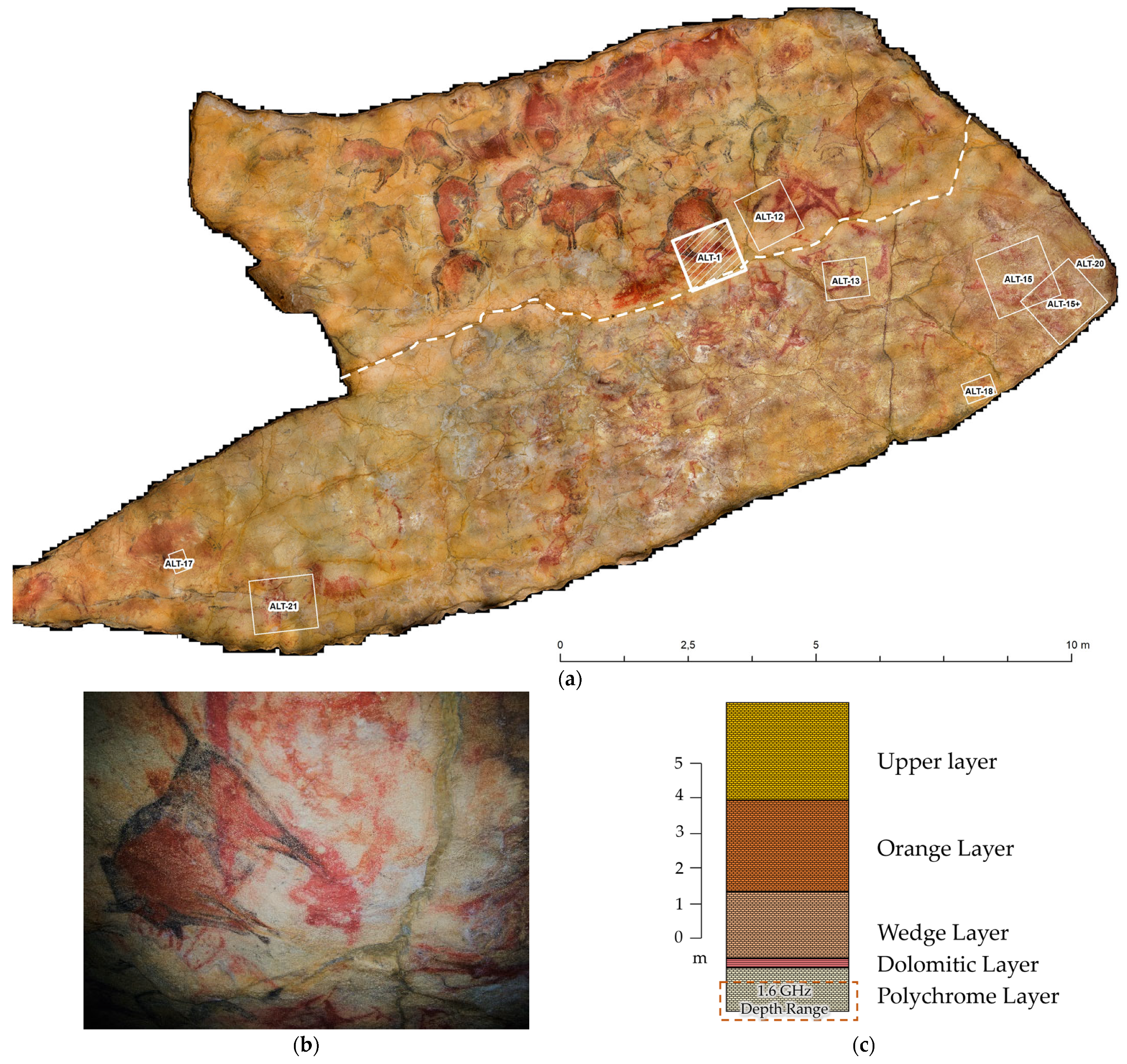
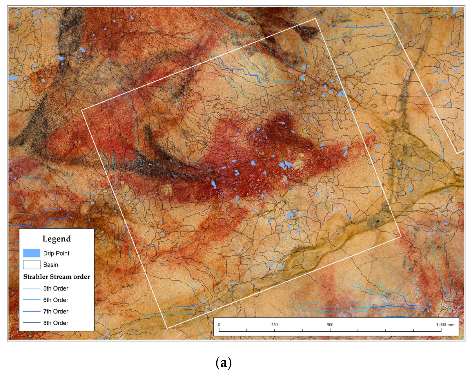
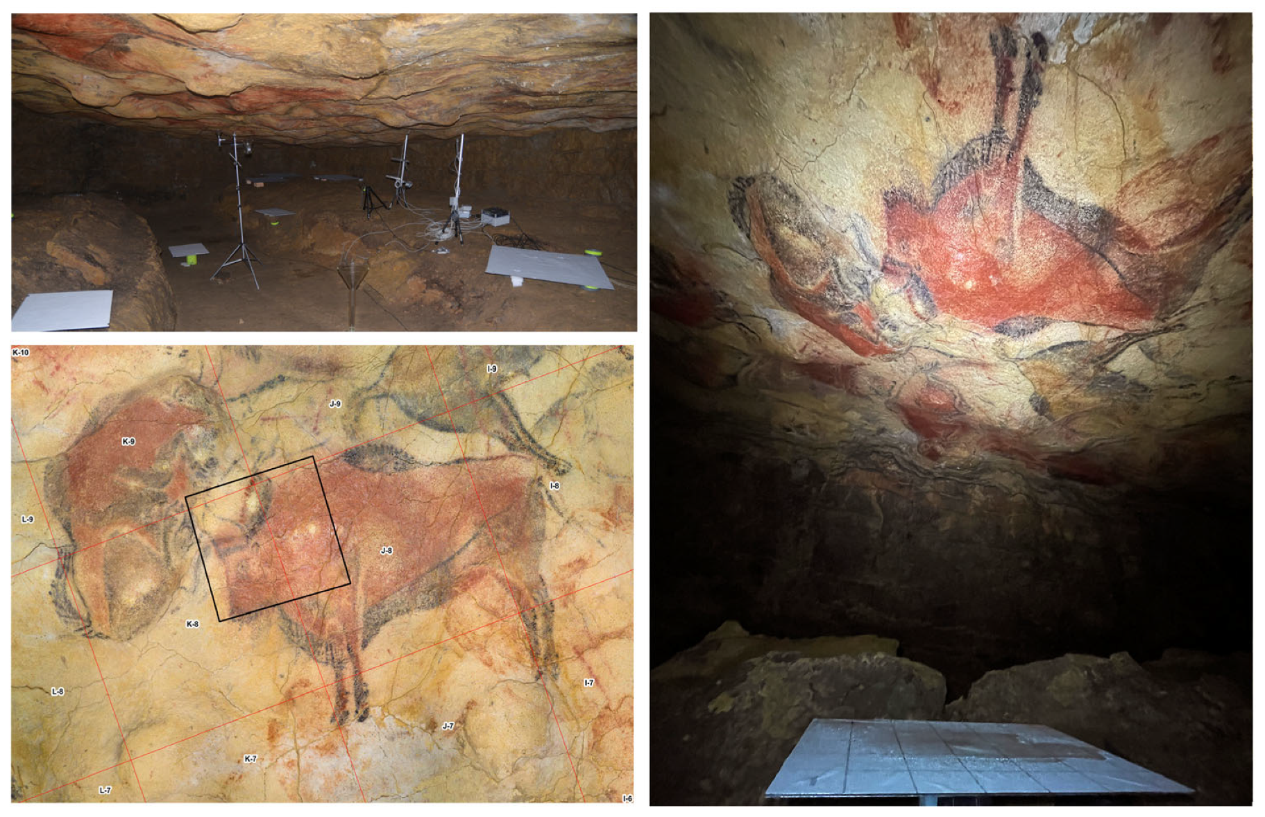
The proposed objective of the GPR technique is the high-resolution mapping of the water flow path in the Polychrome Layer from the Dolomitic Layer. The GPR data have allowed the estimation of discontinuities and moisture zones in the first 50 cm depth from the surface of the Ceiling. In this study, we refer to a control area ALT1 in the center of the Ceiling (Figure 2a). The ALT points depicted on the map represent sensitive areas where either pigment migration and carry-over processes or areas with bacterial growth have been detected. These locations undergo high-resolution microphotogrammetric monitoring to assess their evolution objectively. The control area under study is located on a large red clavicle placed near the legs of one of the large polychrome bison (Figure 2b). Claviforms are abstract signs dating from the Upper Palaeolithic period characterized by their elongated shape with a central bulge, although their precise meaning remains unclear; they are commonly in many caves, especially in the Cantabrian region, suggesting a cultural interaction between regional populations during that era.
The stratigraphy (Figure 2c) of the Polychrome Hall ceiling has been detailed in previous work [9,10,11]. The orange layer, characterized by ochre and orange-colored limestone slabs with intercalated layers of loams and clays, is situated between the fissured layer and the upper level. The fissured layer comprises tableted limestone benches showing distinct morphologies resulting from dissolution processes. Additionally, the dolomitic layer, distinguished by a high degree of dolomitization and ochre coloration transitioning to brown upon alteration, is separated from the Polychrome layer by a fine clayey loam intercalation. These clarifications aim to enhance the reader’s understanding of the stratigraphic composition. The geological layers directly influencing the processes affecting the ALT1 control area are the Polychrome Layer and the Dolomitic Layer [35,36,37]. The Polychrome Layer, a 60–70 cm thick limestone layer, holds particular significance as Palaeolithic paintings were executed on its basal surface, using load-bearing structures and hydroplastic deformation morphology. The Dolomitic Layer, with a thickness ranging from 10–25 cm, exhibits located disintegration processes. The Dolomitic Layer overlies the Polychrome Layer and acts as a protective barrier, providing a degree of impermeability due to its thin intercalation of marls and clays in contact with the Polychrome Layer. Therefore, the Dolomitic Layer safeguards against water infiltration at the Ceiling surface. These two layers provide crucial insights concerning the site.
The results obtained in the Polychrome Layer using the 1.6 GHz antenna and its 3D data integration have allowed:
  • Obtaining a higher-resolution response in the first centimeters of depth from the surface of the Ceiling, where the mentioned red claviform sign is located. This has been complemented with earlier 2D records obtained with the central antenna of 900 MHz frequency.
  • Mapping the spatial configuration of moisture flows present in the study area directly involved in the Polychrome Layer. For this purpose, preferential moisture pathways have been mapped, as well as monitoring of the surface water dynamics, and the main dripping points associated with the migration and detachment processes of pigment.
On the basis of these considerations, the main objective of this study is to provide valuable information that contributes to proposing reliable solutions to improve the conservation of the cave and its art.
Despite significant advances in remote sensing technologies, there are still problems when effectively applying these methodologies as basic tools for conservation in cave environments. Existing research on remote sensing has mainly focused on characterizing cave structures, with limited emphasis on correlating these findings with dynamics related to water infiltration and pigment migrations [40]. The existence of divergent hypotheses about the effectiveness of remote sensing in adopting specific conservation measures highlights the need for comprehensive and standardized methodologies [1]. Key publications in this field have highlighted the importance of remote sensing in obtaining useful basic information to implement measures aimed at safeguarding Cultural Heritage [41,42,43,44], emphasizing the need for interdisciplinary approaches that combine geophysical techniques with geospatial analysis. Controversies arise regarding the reliability and accuracy of remote sensing data, especially in complex cave environments where factors such as rock composition and moisture content vary significantly. As for moisture content, variations arise from different periods throughout the year, influenced by factors such as the access of infiltration water through fractures and fissures or changes in these water dynamics due to punctual variations in the order of moisture pockets or fillings, among others.
In this work, we show how remote sensing methodologies offer a valuable perspective, letting us understand the interaction between degradation agents (such as water/moisture) originating on the surface and, by infiltration, coming into contact with the paintings on the ceilings and walls of the Cave of Altamira. Taking advantage of the capabilities of remote sensing technologies, such as high-frequency GPR and photogrammetry, we aim to evaluate microclimatic environmental factors affecting the stability and integrity of the cave’s ecosystem.
In our study of the Cave of Altamira, our aim was to understand the complex interplay between climatic variations and anthropogenic activities. While our primary focus centered on assessing damage related to moisture and pigment migration, we recognized the significant influence of human interventions on the environmental dynamics within the cave. Anthropogenic activities, such as applying cement mortar to seal fractures and constructing artificial walls, have changed the moisture circulation and microclimate, resulting in notable changes in the ecosystem of the cave.
Historical changes, including the installation of entrance doors and the construction of corridors with artificial lighting, have disrupted the natural state of the cave. These interventions over the past century have transformed the cave of Altamira from an oligotrophic environment to one significantly influenced by external factors related to anthropogenic action. Looking ahead, our research aims to dig deeper into these relationships to develop more comprehensive conservation strategies for safeguarding this invaluable cultural heritage site.
The main conclusions of this study emphasize the importance of integrating remote sensing techniques into conservation practices to preserve Cultural Heritage sites such as the Cave of Altamira. Thanks to high-resolution three-dimensional studies and geospatial analysis, we have improved our understanding of the complex interaction between environmental factors and the degradation of prehistoric paintings. Our findings highlight the essential role of remote sensing in helping with preventive conservation strategies involving decision-making and, in parallel, contributing to the long-term sustainability of these invaluable cultural assets.

2. Materials and Methods

2.1. Study Site

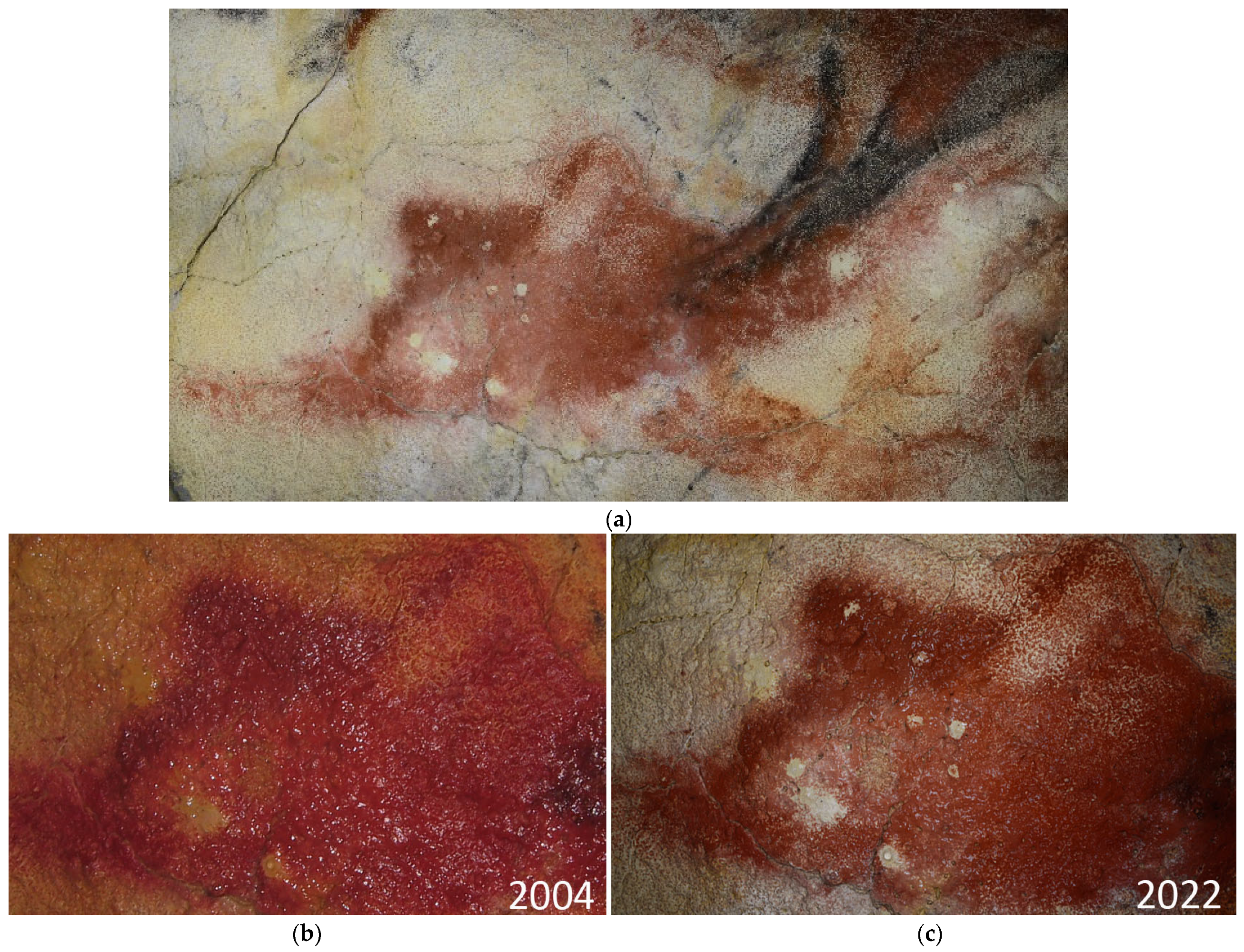
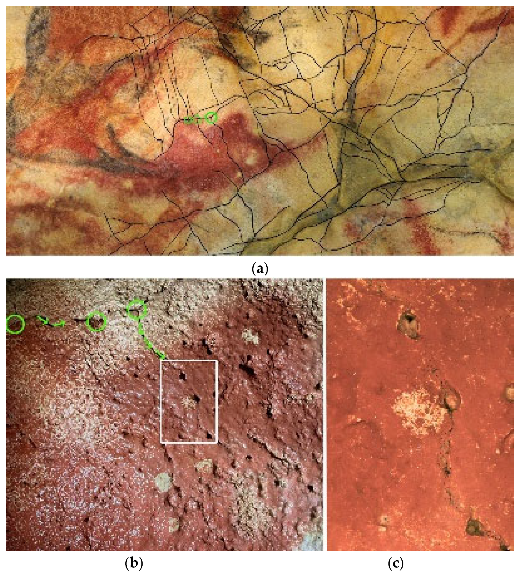
The study focused on the control zone designated as ALT1 located in the central part of the Polychrome Hall ceiling (Figure 3a). This zone covers an area of 1.2 m2 and is arranged around a large red claviform sign located under the hind legs of one of the large polychrome bison. The detail of the sign corresponding to our control area ALT1 affected by various processes of migration and pigment washing associated with drip spots is depicted in the images. In the left image (Figure 3b), the sign seems scarcely affected by migration processes and paint washing. However, the right image (Figure 3c) shows the same sign eighteen years later, exhibiting numerous drip spots that have occasionally washed away the paint. These images collectively illustrate the progression of pigment loss and degradation.
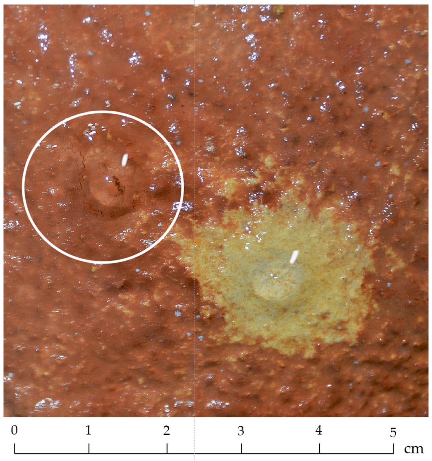
In recent years, ALT1 has been affected by multiple infiltrating water drips that have caused dragging of pigment, leading to migration processes and, ultimately, the deterioration of the painting. This research poses significant challenges aimed at improving the conservation of this area and, by extension, other areas of the Ceiling affected by these same deterioration processes associated with water infiltration and consequent pigment dragging [45].

2.2. General Workflow Diagram

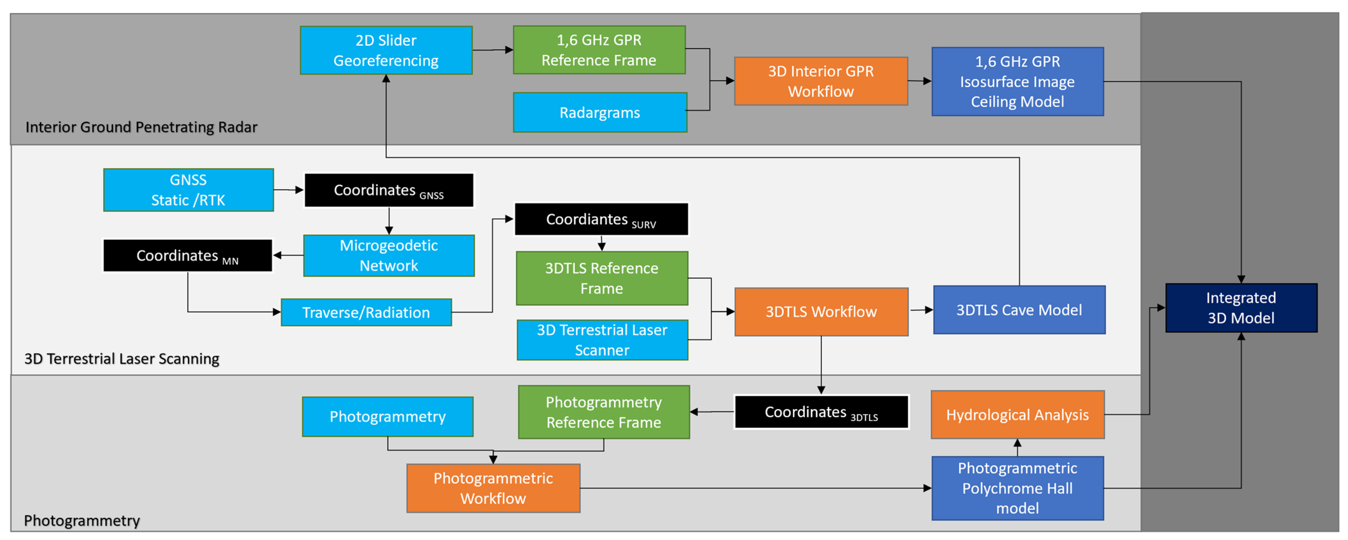
Integrating data into the model (Figure 4) begins with establishing a reference frame using the precision of the Global Navigation Satellite System (GNSS) [46,47]. At first, in 2013, Topcon Hyper II receivers [48] were used to establish a geodetic reference system aligned with the European Terrestrial Reference System 1989 (ETRS89). Evaluating observed phase changes, aided by Topcon Tools 8.2 software [49], yielded a reference frame with an average accuracy of 1.7 cm for determining the coordinates of exterior cave vertices by using the method described in [50].
To ensure an accurate cartographic model of the cave, precise 3DTLS methods were employed [42]. The process began from a closed traverse adjusted and compensated through the cave using a Topcon GPT-7503 (Topcon Corporation, Tokyo, Japan) total station [51]. Sixteen traverse stations were established, covering a total length of 430 m, with an angular closure error of 0.0218 g and a linear closure error of X = −0.001 m, Y = −0.005 m, Z = 0. A total of 66 checkerboards, distributed throughout the cave, served as reference points for the 3DTLS, ensuring precise georeferencing of scans. The field campaign, conducted in December 2013, used a Faro Focus X-130 (Faro Technologies Inc., Lake Mary, FL, USA) [52], requiring 300 scans. Calibrated spheres were employed as tie points, while traverse checkerboards served as references, achieving an adjustment accuracy of 2.7 mm for 95% of the points [53]. In a previous photogrammetry campaign conducted in 2014, the Polychrome Hall Ceiling was documented using a Hasselblad H4 D-200 MS (Gothenburg, Sweden) camera, achieving a minimum resolution of 16 pixels/mm2. The photogrammetric process involved detecting homologous points extracted from the 3DTLS point clouds, strategically placing eighty evenly distributed points throughout the hall, with half serving as control points for model validation. These images were collectively adjusted to generate a high-density point cloud containing approximately 11 billion points, which was then filtered and generalized to produce another point cloud containing around 3.5 billion points. From this refined dataset, a high-resolution 3D digital model of the Ceiling was generated, comprising approximately 200 million polygons. This model facilitated the creation of a 6 Gigapixel orthoimage and a simplified version with 4 million polygons, enabling accurate integration. Utilizing the geometric models, hydrology calculations were conducted to comprehend the dynamics of water movement across the overlying layer and Polychrome Ceiling surface, analyzing surface water flow patterns and identifying potential entry points for water infiltration towards the Polychrome Hall [35,36,37]. Finally, a dual-axis slider employing three 1.2 m sliders aimed to cover a 1 m2 control area (ALT-1), with precise positioning achieved through scanning and 5 cm equidistance interval profiling.

2.3. Remote Sensing Methods

2.3.1. Photogrammetry of the Polychrome Ceiling

The documentation of horizontal surfaces associated with gravitational issues poses challenges due to complexity and inaccessibility, prompting the use of advanced remote sensing techniques [53,54]. In 2014, a photogrammetry campaign was conducted to document the Polychrome Hall ceiling [55], complementing laser scanning with a sub-millimeter resolution. The Hasselblad H4 D-200 MS camera, chosen for its R-G-B color capture and geometric accuracy, used HC 3.5/35 and HC 4/28 lenses, capturing frames at 8176 × 6132 pixels resolution. At least 16 pixels/mm² was maintained, with two 4800 Kelvin-degree LED screens providing 980 lux illumination, diffused with Rosco Cinegel 3000 Tough Rolux plastic.
Photogrammetric support involved homologous point detection from the 3DTLS point clouds. Eighty evenly distributed points, half serving as controls, were placed throughout the Hall. These images were collectively adjusted to generate a high-density point cloud of approximately 11 billion points. Subsequent filtering and generalization produced a refined point cloud with around 3.5 billion points. From this dataset, a high-resolution 3D digital model was generated, boasting approximately 200 million polygons. This model helped with the creation of a 6 Gigapixel orthoimage and a simplified 4 million polygon version, ensuring seamless integration for the study of rock art and the associated processes of alteration. Once the geometric models were available, hydrological calculations were carried out, as understanding the dynamics of water flow through the overlying layer and the ceiling surface of the Polychrome Hall plays a fundamental role in understanding the active alteration processes associated with the ceiling surface paintings.
The data collected in 2014 maintain their relevance and reliability for our analysis, even considering potential changes in the cave’s condition. The photogrammetric campaign conducted in 2014 provided valuable insights into the cave’s micro-morphological particularities, particularly regarding pigment conditions and surface alterations. While minor changes may have occurred since then related to microcorrosion processes of the supporting rock, these are at the micron level and are very subtle changes. These are unlikely to significantly affect the integrity of the data or the accuracy of our analysis. Additionally, ongoing monitoring efforts, including annual high-resolution photogrammetry of key zones like ALT1, ensure that any changes are captured and accounted for in our assessments. So, we affirm that the data from 2014 remain a robust foundation for our hydrological calculations and the understanding of alteration processes within the cave.
The aim of integrating the geometric models with hydrological analyses was to gain insights into how water interacts with the internal structure of the Ceiling over time, revealing patterns of erosion, disintegration, concretion, and moisture infiltration, potentially revealing patterns.

2.3.2. GPR of ALT1 Control Area

The GPR technique consists of the propagation of short electromagnetic pulses (t ≤ 1 ns) in a medium. These pulses reflect when there are changes in the electromagnetic properties of the medium (magnetic permittivity, electrical conductivity, and dielectric permittivity). So, the characteristics of the GPR signal are strongly influenced by the electromagnetic properties of the medium and their contrasts with each other. The contributions of electrical conductivity and magnetic permeability to the recorded signal cannot be distinguished in typical GPR studies using frequencies between 8 MHz and 2.5 GHz [56,57]. In low-loss media, the dielectric permittivity (εr) can be estimated by the equation [58,59]:
ε r = c t 2 h 2  
where h is the depth of the layer, t is the two-way travel time (elapsed time) in the GPR profile, and c is the velocity of light (0.299 m/ns). The mean velocity (v) is derived from:
v = c ε r
The amplitude of a registered signal is a function of several factors: the amplitude of the transmitted signal, the geometrical dispersion (and thus the travel distance), the reflection coefficients between the interfaces (due to targets causing reflection and refraction of the signal), the signal scattering (due to small targets causing scattering), and the absorption of the medium.
The absorption of the medium is defined by the attenuation coefficient α. The attenuation coefficient is dependent on several factors (the angular frequency (ω), the electrical conductivity (σ), the dielectric permittivity (ε), and the magnetic permeability (μ)), as given in Equation (3) [60], with the average conductivity and the dielectric permittivity of the medium being key influences:
α = ω μ ε   1 2   1 + σ ω ε 2 1 1 2  
Since most of the GPR studies are carried out in non-magnetic media (low-loss media), in this, case Equation (3) simplifies to Equation (4) [61]:
σ ω ε                 α = σ 2 μ ε
Equations (3) and (4) show the dependence on the dielectric parameters of the media that depend on their physical properties, with the water content being one of the important factors. This attenuation coefficient α represents the amplitude behavior during the propagation of the electromagnetic wave through the medium as a result of energy absorption.
The reflection amplitudes at the two-material interface can be estimated using the reflection coefficient (R). GPR signal reflection amplitudes and intensities are proportional to the contrasts of the dielectric permittivities at the reflector boundaries and depend on the reflection coefficients. In non-magnetic media (low-loss media), expressions for the approximate electromagnetic impedance (Z) and reflection coefficient (R) for two media are given by [59,60,62]:
Z 1 = 1 ε r 1 ; Z 2 = 1 ε r 2 ;   R = ε r 1 ε r 2 ε r 1 + ε r 2   = Z 2 Z 1 Z 2 + Z 1  
where εr1 is the dielectric permittivity of the upper layer and εr2 is the dielectric permittivity of the lower layer; Z1 is the electromagnetic impedance of the upper layer and Z2 is the electromagnetic impedance of the lower layer.
This reflection coefficient equation implies that the greater the contrast between the two media, the higher the percentage of incident energy that will be reflected at the boundary/discontinuity of the reflector. If the moisture/water content in a medium is significant, this moisture/water content becomes an influential factor for the values of dielectric permittivities of materials/media, as the dielectric permittivity of water (81) is higher than that of any other geological material (3–40) [59,63].
Thus, a higher water content in the interior of the medium results in two effects on the amplitude of the electromagnetic wave:
  • The effect of attenuation on the amplitude is a derivative of the attenuation coefficient. The amplitude of the wave propagating through the materials/media decreases drastically as a function of the degree of moisture. Consequently, the wave is attenuated and the wave incident on the targets within the medium generates a low-amplitude anomaly in the radar records, and in some cases, the anomalies may not even be visible [22,64,65,66,67,68].
  • An additional effect on the amplitude is a function of the reflection coefficient. In the case of surface moisture in areas under dry material/medium, the contrast in dielectric permittivity between the wet and dry media is greater the higher the water content is, increasing the reflection coefficient. This means that the greater the contrast between the electromagnetic parameters of two materials/media that are in contact, the greater the percentage of incident energy that will be reflected at the boundary/discontinuity of the reflector. The strength (amplitude) of the reflected fields is proportional to the magnitude of the dielectric constant. Radar reflections of higher amplitude will occur mainly at interfaces within the same geological layer and at material/media interfaces that have significantly different electromagnetic properties. Thus, the anomaly due to the existence of moist areas has a higher amplitude in the reflection profile, as has been reported by different authors [20,37,60,68,69,70,71,72,73,74].
As shown in Figure 2c, the rock medium studied with the 1.6 GHz antenna has been limited to the limestone Polychrome Layer due to the depth of penetration achieved. The surface tension water and active drip points observed on the ceiling are evidence of internal moisture zones in this limestone layer. In the dry zones of the limestone, the relative dielectric permittivity is lower than in the moist zones [59,69]. The existence of water-affected (moister) zones within the dry limestone medium produces interfaces with different relative dielectric permittivities. In the dry zones, the relative dielectric permittivity is lower than in the water-affected (moister) zones. As a consequence, when the wave reaches these interfaces, part of the energy is reflected. According to expression (5), high-amplitude radar reflections are also generated at the interfaces of the water-affected (moister) and dry zones of the Polychrome Layer. It is relevant to notice that the existence of moisture in the interior of the limestone medium (Polychrome Layer) causes the limestone–water interface to have a higher dielectric contrast than the limestone–air interface and, consequently, a stronger reflection [69,70,75].
GPR signal penetration and detection resolution depend on the antenna frequency used. Higher-frequency antennas offer better detection resolution but also increase signal attenuation, which results in lower penetration into rocks [59]. The penetration depth at which the GPR technique can record discontinuities within a rock mass is strongly influenced by its electromagnetic parameters (dielectric permittivity, electrical conductivity, and magnetic permeability). Variations in the electromagnetic parameter values can indicate alterations in the rock and conductive minerals, porosity, joints, fractures, water content, and fillings within the discontinuities. In geological media, the attenuation factor increases as the conductivity of the medium increases. In addition, the propagation of electromagnetic waves in a rock mass is also affected by attenuation due to the degree of water saturation, water mineralization, distance, porosity variation, and the number of discontinuities [60,76,77,78,79]. The high-frequency antenna choice (>1 GHz) provides a higher resolution in detecting the dimensions and geometries of reflectors/elements in a medium, which may be associated with internal changes/discontinuities [58,80,81]. However, the penetration depth with these high-frequency antennas is lower than the 900 and 400 MHz central-frequency antennas used in earlier GPR campaigns. Due to the range in penetration depth of high-frequency antennas (>1 GHz), this survey was focused on the Polychrome Layer.
The comparison between antennas in GPR studies highlights a trade-off between resolution and penetration depth. The high-frequency antenna offers superior resolution, capable of detecting features as small as 2 cm, but its penetration depth is limited to 0.4 m. However, the low-frequency antenna provides a lower resolution but can penetrate up to 4.5 m, making it more suitable for deeper subsurface investigations [56,58,82,83,84,85,86]. The choice of antenna is closely related to the resolution of a specific conservation problem as accurately as possible: the washing of paint, which is directly linked to water accumulated in the first centimeters from the basal surface of the Ceiling. This justifies the use of a higher-frequency antenna (higher resolution and lower penetration), as shown in Table 1. Additionally, addressing deeper accumulations indirectly requires an antenna with greater penetration. Ultimately, the objective is to respond to a conservation need, balancing the requirement for resolution against the need for depth penetration to ensure optimal results in subsurface imaging and detection applications [56,58,82,83,84,85,86].
The digital processing of time-domain GPR data generally relies on the amplitude values of the signal for interpretation. Furthermore, the transformation of the GPR data into its instantaneous magnitude, phase, and frequency information requires additional processing of the GPR data. The Hilbert transform has been applied to complex rock masses to enhance the reflection and absorption contrasts of electromagnetic wave propagation. Thus, GPR attributes can reveal or highlight features or patterns that are not clear in standard amplitude data [86,87,88].
In this study, using Hilbert transform attributes in the interpretation of GPR data can help us to increase our knowledge of the internal structure of the Polychrome Layer by characterizing the electromagnetic response to the moisture zones within it.

2.3.3. GPR Data Acquisition

The high-resolution GPR survey was performed using an SIR 4000 system manufactured by Geophysical Survey Systems, Inc. (GSSI, Nashua, NH, USA). The GPR system was equipped with a 1.6 GHz central frequency antenna. The choice of a high-frequency antenna (>1 GHz) was intended to improve the resolution in detecting internal reflectors and changes/disruptions at a 50 cm depth in the Polychrome Hall ceiling. This antenna configuration provided depth penetration ranging from 0 cm to approximately 50–60 cm, depending on the medium and its electromagnetic properties, while maintaining a high-resolution capability [58,80].
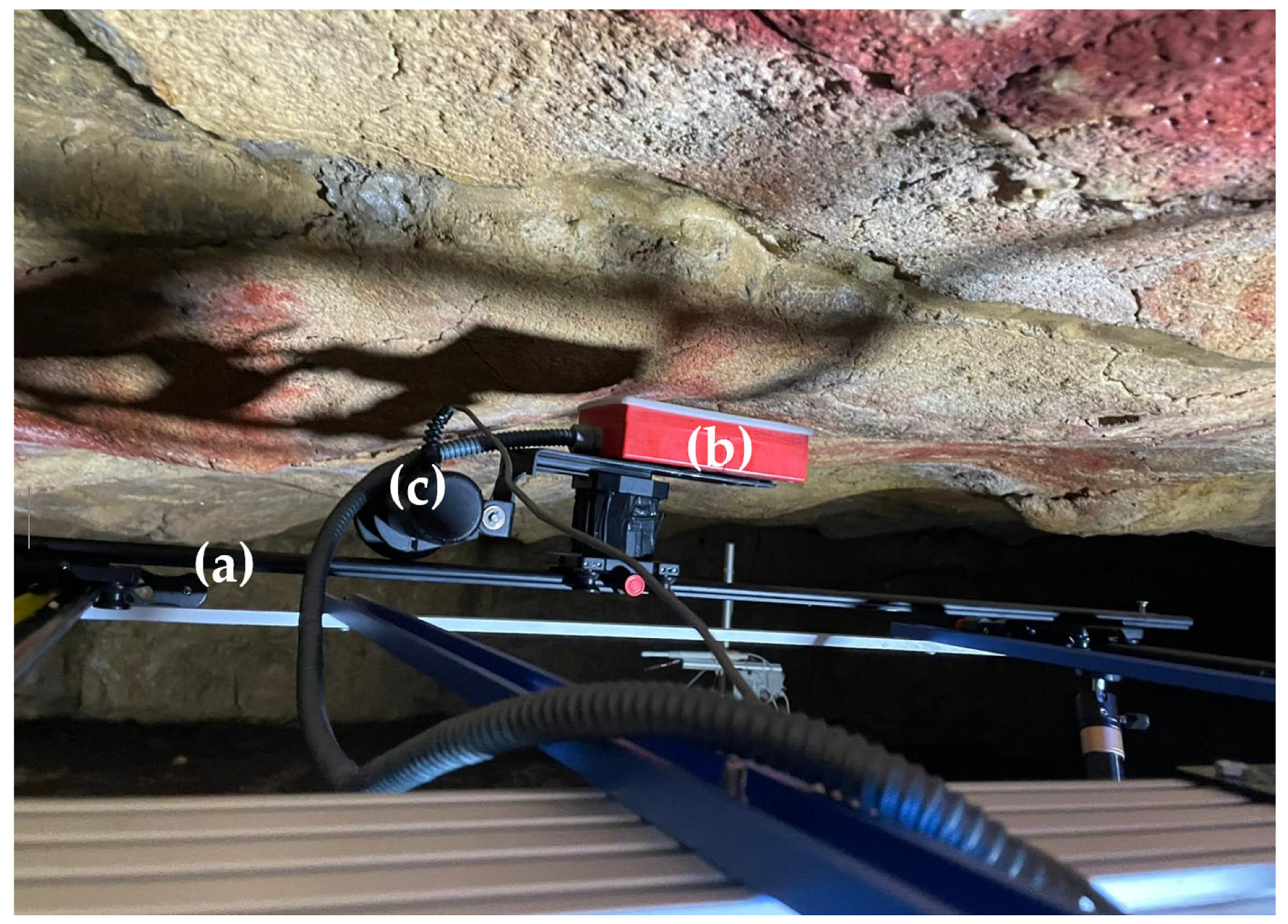
Due to the presence of Palaeolithic paintings on the Ceiling, the GPR data were collected with the air-coupled antenna on the Polychrome Hall Ceiling to avoid any contact between the antenna and the Ceiling that could cause damage to the cave paintings. It had to be assumed that the antenna height would affect the data recording process. To reduce this effect and consider the minimum allowable distance to the rock paintings on the Ceiling, data acquisition was performed at a height depending on the 1.6 GHz central-frequency antenna of 10 cm (Figure 5). This height ensured the maximum possible amount of energy transmitted to the rock mass and reduced the effects of coupling to the air to obtain accurate and high-quality GPR records [89,90]. This antenna configuration provided a penetration depth of up to approximately 50 cm into the Polychrome Layer, while maintaining a high-resolution capability [58,80,81].
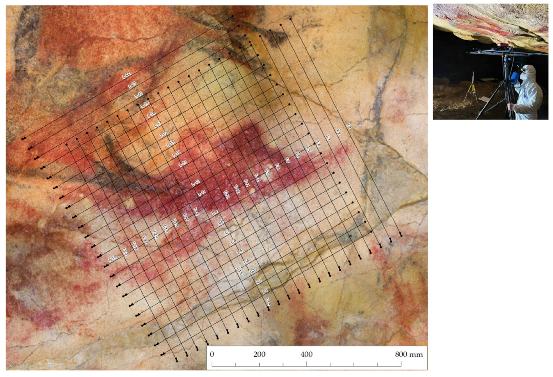
A 1 m-long slider was chosen due to operative limitations inside the cave, on which the 1.6 GHz antenna was placed, focusing on the Ceiling (Figure 5). An odometer wheel (encoder) was used to calculate trace-interval distance. Further, the reflection profiles were georeferenced through 3D scanning of the sliders where the antenna was fit.
The survey aimed to spatially map the internal distribution of moisture in ALT1 and its immediate surroundings. To achieve this, a 5 cm × 5 cm grid pattern was designed specifically for ALT1, including 23 longitudinal and 23 transverse profiles. These profiles were strategically laid out and numbered for the study’s purposes, as illustrated in Figure 6. Additionally, a square grid measuring 1 × 1 m was established, using equidistant orthogonal 2D lines spaced every 5 cm. This grid was centered on the ALT1 control point, as depicted in Figure 5, with the 2D lines oriented transversally and parallel to the central fracture of the Polychrome Hall ceiling. This approach helped with comprehensive data collection and analysis of moisture distribution within the designated area.

2.3.4. GPR Data Processing

The GPR wave mean velocity was determined by the hyperbolic fitting method on a set of hyperbolas recorded in different reflection profiles, resulting in a mean velocity value of 0.111 m/ns. The dielectric permittivity (ɛ) was calculated to be 7.2, according to Equation (2). To calculate the processed depths in the investigated polychromatic layer, this value was applied. This mean velocity was also used in the Kirchhoff migration for the 2D processing of the GPR data.
The raw field GPR dataset needs to have a post-acquisition processing procedure applied to it before generating amplitude maps and rendering 3D images with all reflection profiles on a grid. There are several techniques for post-acquisition processing of radar signals. In this study, a basic data-processing procedure and a Hilbert transform attribute (instantaneous magnitude) were applied to the raw dataset, using RADAN 7.6 software (Geophysical Survey Systems, Inc., GSSI, Nashua, NH, USA) [91]. The first step was 1D processing consisting of zero-time correction (time-zero adjustment). After this, the 2D processing was applied for the reflection profiles according to the following steps: (i) background removal filter; (ii) bandpass filter; (iii) linear amplitude gains; (v) Kirchhoff migration filter using the calculated average velocity (0.111 m/ns); (vi) a time-to-depth conversion performed based on a calculated velocity mean velocity of 0.111 m/ns for the limestone of the Polychrome Layer; (vii) Hilbert transform attribute: instantaneous magnitude. Next, each processed reflector profile was aligned within the grid to generate horizontal amplitude 3D maps and isosurface (isoattribute-surface) images that allowed us to pinpoint the presence of significant moisture/water zones. Several amplitude slice maps were created at different levels for mapping the subsurface up to depths of 36 cm. Amplitude depth-slice maps from the 3D model were used to identify moisture/water zones at a constant depth. Once the depth-slice maps had been generated, the highest amplitudes in all profiles within the grid were rendered in an isosurface image. This isosurface image was colored to show certain amplitude values (the highest ones) while others were made transparent in order to best represent only moisture/water zones and simplify locating moisture/water zones and their interpretation. This transparent visualization of the 3D GPR dataset was performed to reveal the main moisture/water zones in this studied volume of the Polychrome Layer.

2.4. Polychrome Ceiling Hydrology

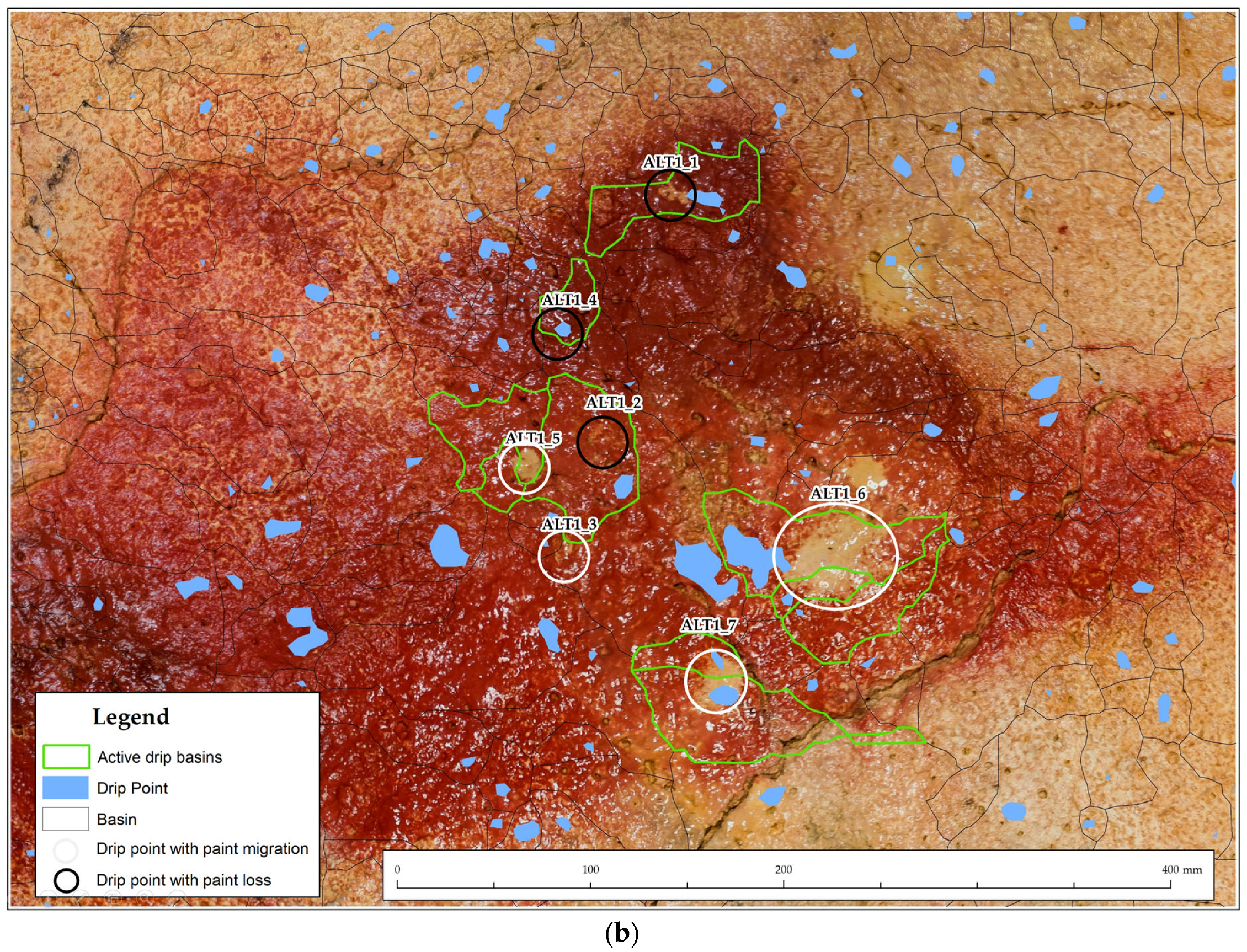
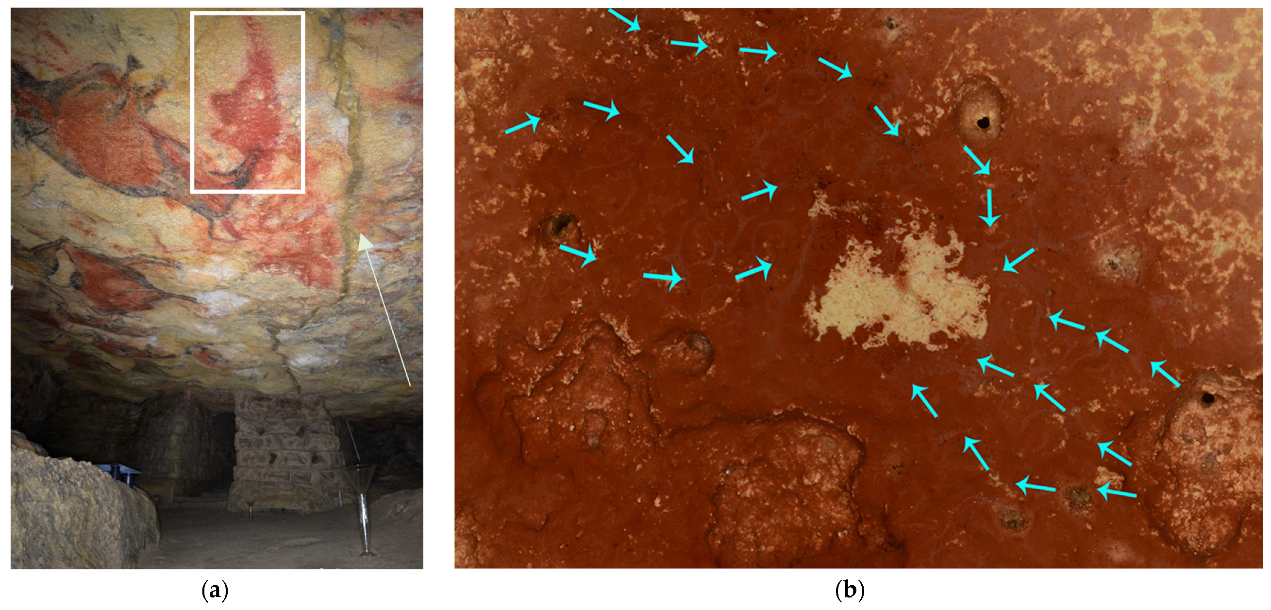
Modeling water movement within the cave’s interior poses a significant challenge, particularly in the Polychrome Hall ceiling where water primarily moves under the influence of surface tension. This phenomenon occurs as water infiltrates through the porous and fractured limestone rock, guided by capillary forces and the cohesive properties of water molecules [92,93,94]. GIS technologies play an important role in accurately modeling this process. Identifying the drip points involved that induce processes of erosion, flaking, disintegration, and washing by dissolution of some of the mineral parts, including the constituent pigments of the Altamira art (Figure 7), holds profound implications for cave conservation. Understanding the flow paths and points of ingress is essential for predicting the potential damage and degradation of rock paintings.
The workflow involves using a 3D high-resolution photogrammetric model to conduct a hydrological analysis [95] in QGIS [96], aimed at elucidating the sources and destinations of water within the area. Various analytical functions, including the Strahler method [97], are applied to accurately represent water flow dynamics over the Ceiling.
The Strahler method assigns numerical values to segments of a raster, reflecting branches in a linear network. It classifies streams based on their tributary counts, with an increase in stream order at intersections. The “Basin” function delineates drainage basins by identifying ridge lines that separate them, which is important for understanding spatial water distribution [98]. Using input flow direction raster data, the analysis identifies connected cells within the same basin. The “Flow Distance” analysis calculates horizontal or vertical downslope distances along flow paths to converging stream cells, helping with the computation of various flow distance metrics.
The workflow includes the addition of drip-point calculation, which concerns specific locations within the cave Ceiling where accumulated water reaches a critical saturation point and drips down and constitutes an important feature to map and understand. They can significantly affect rock art deterioration, cave formations, water quality, and ecological dynamics (Figure 8). By simulating water movement and saturation levels within the cave Ceiling, GIS aids in predicting the precise areas of dripping. Identifying these drip points is important for geological and hydrological research and conservation efforts. It allows for tracking potential erosion, calcification growth, and the transport of water chemistry and nutrients to the cave floor, influencing unique cave ecosystems. All this information allows the managers of the Cave of Altamira to make decisions to anticipate damage to reduce the deterioration of the cave and the paintings it houses.

3. Results

The results obtained with the 1.6 GHz antenna shown in Section 3.1 indicate the distribution of moisture in the internal part and for the first 36 cm from the surface of the Polychrome Hall ceiling in the ALT1 control zone. Hydrographic calculations based on a three-dimensional model reveal the dynamics of water flow on the Ceiling, aiding in understanding the active fissures involved in pigment drag processes, as well as related drip points (Section 3.2). Six relevant moisture zones with varying elevations and characteristics are observed. These zones are linked to surface microchannels and the large central fracture mapped in previous campaigns (2017 and 2018) as shown in Section 3.3. Despite encountering some issues with data acquisition using the antenna, such as noise interferences and depth limitations, the results allow for the interpretation of water and moisture access dynamics to the Ceiling surface. This information lays the groundwork for applying conservation strategies to minimize deteriorations related to infiltration water on the Polychrome Hall ceiling of the Cave of Altamira.

3.1. Moisture Mapping in ALT1

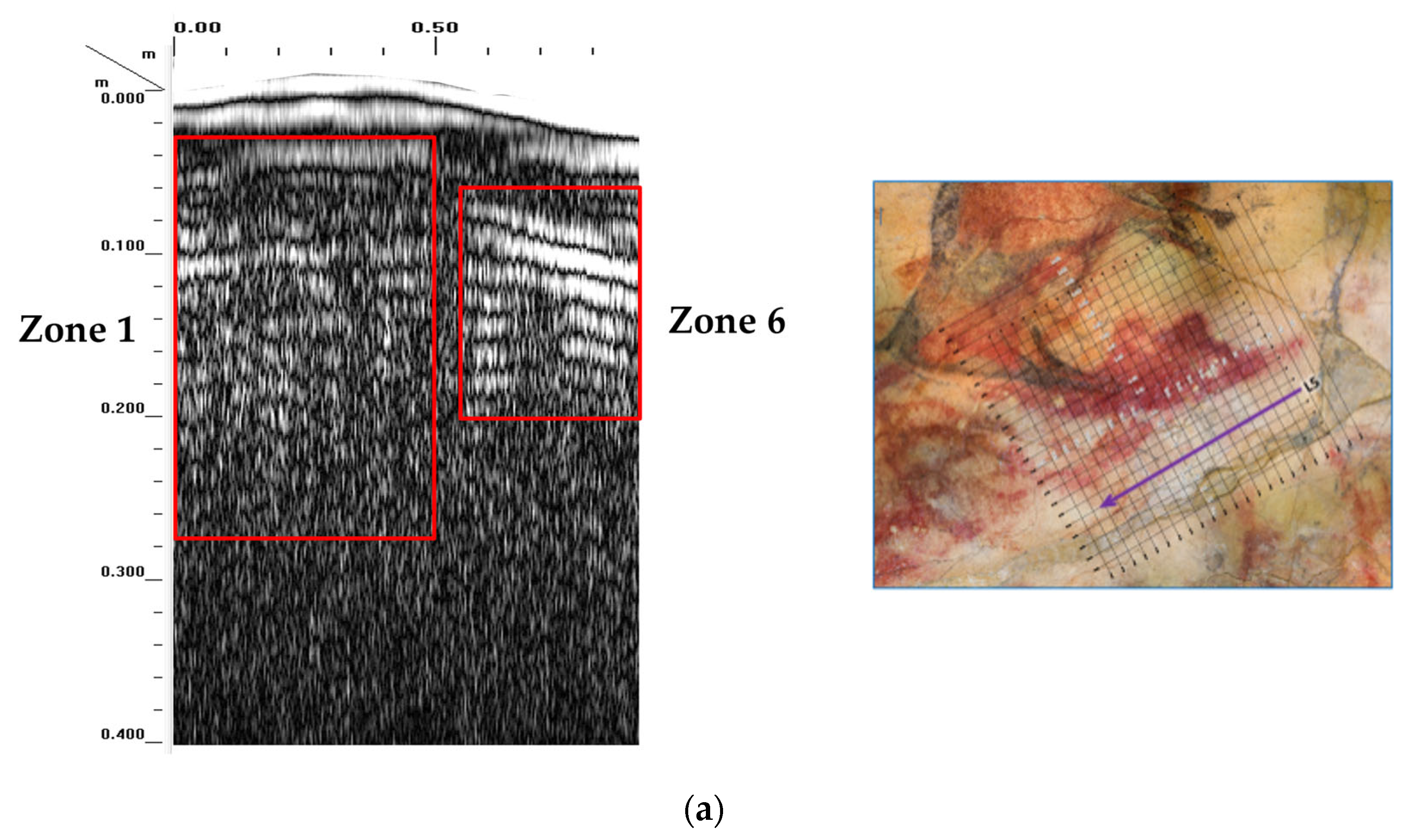
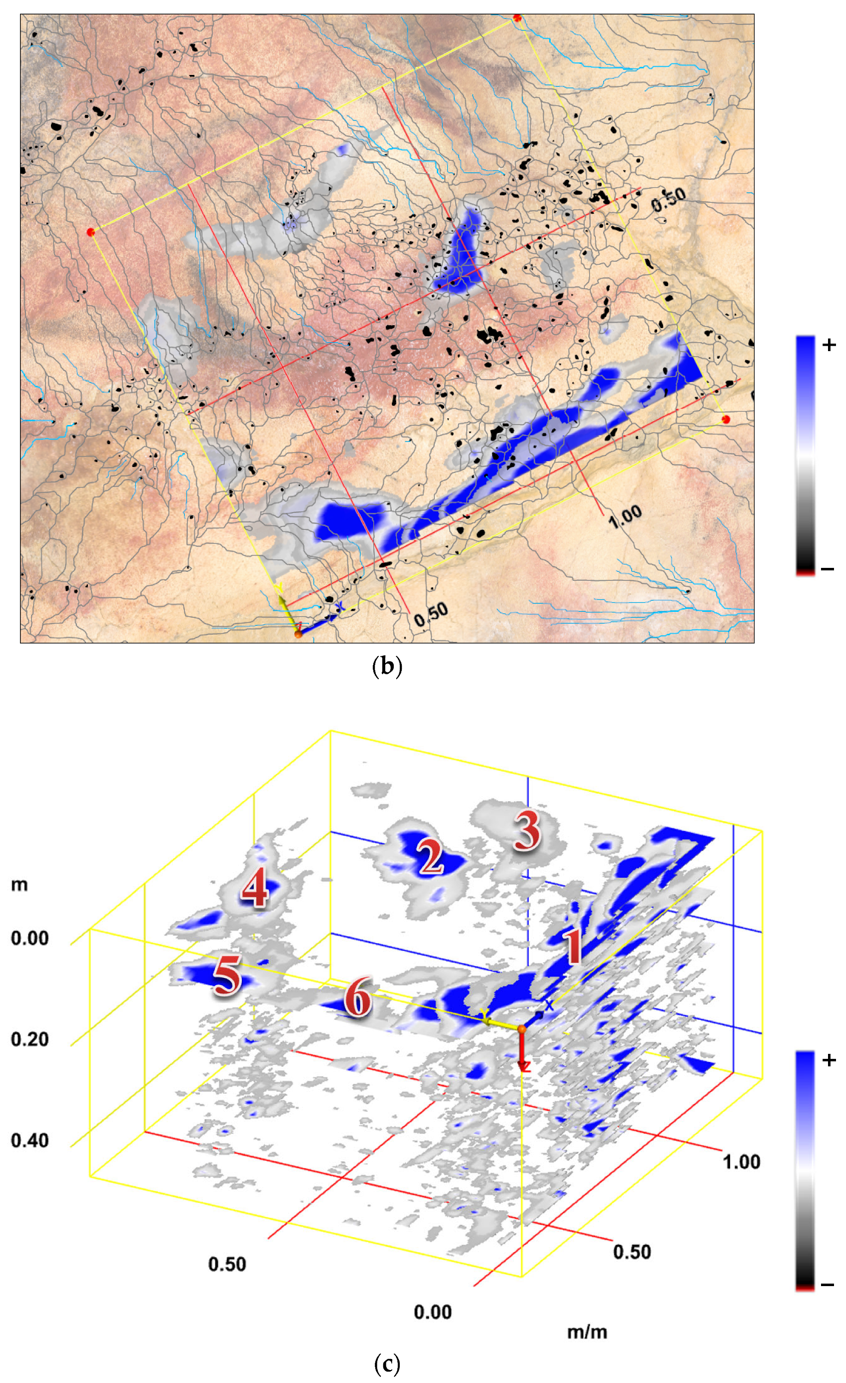
In the ALT1 control zone, after processing GPR data, six high-moisture zones were detected, each with different characteristics (Figure 9b,c):
  • Moisture Zone 1 is strongly associated with the geometry of the central fracture mapped in the 2017/2018 campaigns. This moisture accumulation is parallel to the central fracture and reaches a depth of 36 cm (Figure 9a). Moisture Zone 1 results from the moisture concentration in areas adjacent to the central fracture due to the dam effect generated by the injection of cement mortar applied over the entire development of this large fracture crossing the Ceiling from west to east (Figure 2a). The antenna information shows the existence of discontinuities in the mortar, indicating partial degradation, disintegration, or deterioration at certain points. Additionally, the antenna indicates that the depth of this injected filling from the early last century presents a variable thickness.
  • Moisture Zone 2 is closely associated with drip points ALT1_1, ALT1_2, and ALT1_4 as shown in Figure 7b, between 3 cm and 5 cm deep. Its highest moisture concentration is at a depth of 3 cm.
  • Moisture Zone 3 is between 2 cm and 12 cm deep. Its highest moisture concentration is at a depth of 2 cm.
  • Moisture Zone 4 is associated with the vertical fractures mapped in the 2017/2018 campaigns and projected into the belly of the large bison associated with our ALT1 control zone. It ranges from 2 cm to 36 cm deep.
  • Moisture Zone 5 is between 6 cm and 12 cm deep. Its highest moisture concentration is at a depth of 7 cm.
  • Moisture Zone 6 is between 6 cm and 19 cm deep. Its highest moisture concentration is at a depth of 6–7 cm (Figure 9a).
These described moisture zones correlate with both the large fractures (mapped in the 2017 and 2018 campaigns) that develop vertically from the first meters of the overlying layer towards the Ceiling surface and the small fissures or fractures observed on the surface, acting as small moisture inputs (Figure 10). All of this ultimately combines in the different surface microchannels leading to the respective drip points.

3.2. Hydrology of the Polychrome Ceiling

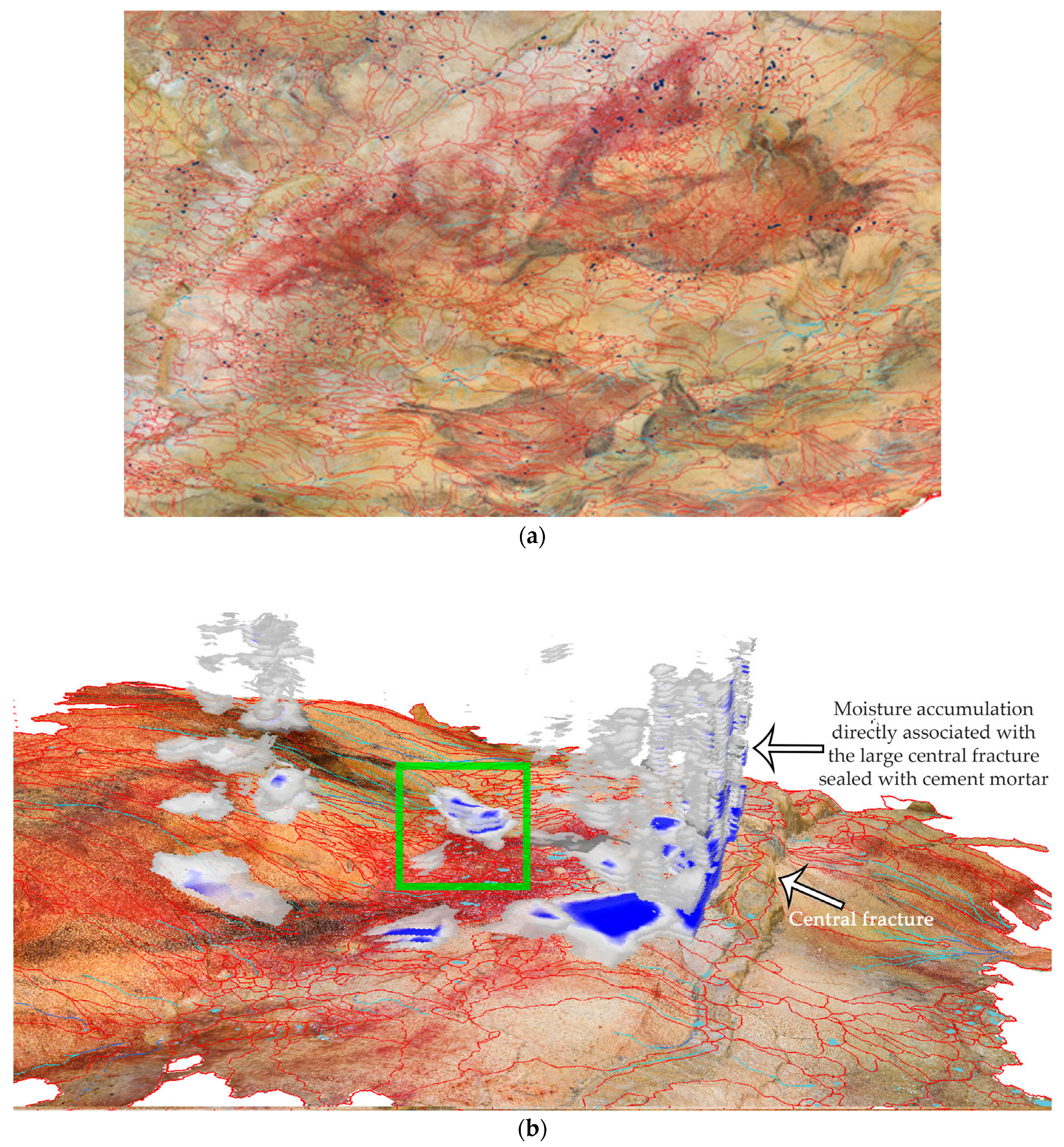
Hydrographic calculations have been carried out using a detailed 3D model with a ground sampling distance (GSD) of less than 200 microns to reveal critical geological characteristics. The main objective is to identify the contribution basins, streams, and drip points, providing information on the dynamics of water flow in the studied environment. The obtained basins constitute an important metric that allows an understanding of the extent and activity of the fissures. In parallel, channels are accurately mapped to discern the trajectory of water flow, including possible pathways for pigment drag and other potential deposits such as clays or limestone particles, in some cases related to microcorrosion processes induced by another significant alteration agent present in caves such as CO2 [99,100,101,102]. This high-resolution model helps to thoroughly examine the hydrographic network, contributing to a global understanding of the existing hydrogeological dynamics on the Polychrome Hall ceiling (Figure 11).
To ensure the accuracy and validity of hydrographic calculations, a rigorous validation process has been executed. The results are compared with real field observations or through orthoimages, thus verifying the accuracy of the calculated drip points. This verification step is essential to affirm the fidelity of the 3D model predictions, aligning virtual representations with real geological features. In this verification process, information obtained through the so-called “witnesses” located on the floor of the Polychrome Hall is also important (Figure 12). These witnesses, covering an area of 1 × 1 m, are made of rigid material formed from two thin aluminum sheets joined to a solid polyethylene core and lined with a 100% synthetic fabric made of high-density polyethylene fibers, which are lightweight, durable, breathable, and resistant to water, abrasion, and bacterial penetration. The witnesses are georeferenced, allowing the documentation of any dripping from a specific area of the Ceiling surface. Their information, combined with the aforementioned hydrological study, determines the origin of clay, limestone, and pigment drag deposits. This valuable information is transferred to a series of tables that inform us of the dynamics and periodicity of these events [103].
The importance of these hydrographic calculations goes beyond mere visualization as they provide valuable information about water distribution and pathways in the inner part of the Ceiling (see Figure 11). Drip points, indicating areas where water ultimately precipitates, are important indicators of the hydrological behavior of the environment. This detailed analysis not only improves the understanding of water access through active fissures and water channels but also sheds light on specific areas where water interacts with the cave floor, offering broader insight into the geological processes at play in the studied area.

3.3. The Central Fracture

The presence of a higher degree of superficial moisture, which is concentrated in the central part of the Polychrome Hall ceiling in the form of small laminar water flows on both sides of the large fracture sealed with cement, critically influences some of the pigment drag and washing processes involved in our ALT1 control zone (Figure 13). Geophysical prospecting studies conducted in the Cave of Altamira in recent years have revealed that the large central fracture has vertical development that, from a depth of 1.4 m relative to the exterior surface, penetrates, reaching the actual surface of the Polychrome Hall ceiling. On the other hand, the aforementioned injection with cement mortar acts partially as a ‘plug’, diverting water flows towards adjacent areas, precisely where our ALT1 control zone is located (Figure 11b).

3.4. Limitations and Challenges

The problems regarding data acquisition are derived, among other issues, from the difficulty in locating the areas of interest, as they are situated on the Ceiling, which obviously does not allow any contact of our antennas with its surface. On the other hand, the Ceiling surface is bathed in a thin but constant layer of water, which also conditions data collection. Additionally, there are significant conservation constraints related to both the length of stay and the use of materials inside the Polychrome Hall [1].
Noise interferences and signal attenuation have limited the depth penetration of data acquisition beyond the first 50 cm, making subsurface characterization difficult. The combined use of different antennas and the application of a novel methodology by using antennas from the exterior surface in combination with those applied from the interior of the Polychrome Hall has allowed us, after correlating all the data, to obtain more extensive and more precise information on internal fractures and the moisture involved.
The results reveal complex relationships between the distribution of moisture and its associated fractures and fissures and highlight how certain environmental factors decisively influence the conservation of this type of Cultural Heritage site.

4. Discussion

The results of our study shed light on the complex dynamics of moisture distribution in the Polychrome Hall of the Cave of Altamira. Thanks to the integration of high-resolution GPR data with previous campaigns and geospatial analysis, we have been able to better understand the underlying processes related to the dynamics of infiltrating water affecting the conservation of this Cultural Heritage.
The geophysical prospecting campaign with the 1.6 GHz antenna in the ALT1 control zone and up to the first 50 cm depth allowed us to conclude that the highest amount of internal moisture is found between 10 and 20 cm from the surface, with the least moisture load found at greater depths of above 30 cm. Additionally, the presence of this moisture is mainly related to two lateral contributions, one on the southern side, clearly associated with the large central fracture, and another on the northern side coming from a large fracture of similar development to the central one that even begins at a higher elevation and, discontinuously, reaches almost the same depth as the central one (Figure 10 and Figure 11b).
The greatest water percolation is located towards the northern side, taking as a reference the large central fracture that crosses the Ceiling from west to east. This direction of moisture flow could be explained by:
a) The dip of the strata of the Altamira karst itself.
b) The greater percolation of moisture in the western area of the studied quadrant is due to the sealing with cement mortar applied over this large fracture.

4.1. Interpretation of Results in Light of Previous Studies

Our observations are based on studies carried out in the Cave of Altamira, particularly those using GPR technology with variable frequencies. The use of a 1.6 GHz antenna allowed for improved resolution in detecting wet areas and structural characteristics in the upper layers of the cave Ceiling. A comparison with previous campaigns using lower frequencies helped to better understand subsurface conditions and temporal changes.

4.2. Implications for Conservation Strategies

The identification of different moisture zones, areas, and channels and the origin of deposits detached from the Ceiling, especially those of pigment and limestone and dolomite particles, provides important information as they speak of the activation of a series of deterioration processes associated with microclimatic variations. The correlation between moisture distribution and active drip points underscores the need to adopt proactive conservation measures to mitigate the potential damage caused to rock art by the access and circulation of this infiltrating water on the Ceiling surface.

4.3. Broad Context and Future Research Directions

Our results contribute to the broader discourse on the conservation of Cultural Heritage in cave environments, highlighting the importance of integrating remote sensing methodologies for effective conservation. Future research directions may include:
  • Further studying moisture dynamics and its correlation with seasonal variations to refine conservation strategies.
  • Continuous monitoring of structural stability to assess long-term changes and the effectiveness of possible conservation interventions.
Considering these lines of research would advance our understanding of the complex interactions that shape the preservation of such valuable Cultural Heritage, which in turn would help implement new and more effective preventive conservation strategies. Establishing sustainable practices based on knowledge of these active deterioration processes will enable the activation of new control and monitoring protocols. Ultimately, this will put us in a better position to understand the processes involved in the deterioration of rock art, allowing us to anticipate damage and foresee deterioration in top-tier Heritage Sites such as the Cave of Altamira.

5. Conclusions

Our study represents a significant advancement in understanding the deterioration factors involved in the conservation of art in the Cave of Altamira, especially in the Polychrome Hall. Leveraging advanced remote sensing techniques, particularly high-frequency Ground-Penetrating Radar (GPR), along with geospatial analysis, we have achieved a comprehensive characterization of moisture distribution, and the constraints affecting the structural stability of the Ceiling have been better understood.
The data obtained provide relevant insights into the factors influencing the degradation and conservation of the cave’s prehistoric paintings, elucidating the complex interaction between climatic influences, anthropogenic activities, and geological characteristics. By delineating moisture zones and identifying detachment areas, we have established a foundation for implementing new preventive conservation strategies aimed at mitigating risks and proposing measures to safeguard this invaluable Cultural Heritage.
This study underscores the importance of interdisciplinary collaboration among professionals from different fields to address the multiple challenges posed by the conservation of this type of Heritage. By integrating research for conservation purposes, we can develop holistic approaches focused on the long-term sustainability of these heritage sites.
The research has allowed us to determine the trajectory of water movement in the first 50 cm from the ceiling surface, enabling the identification of the main internal structural discontinuities involved in water access to areas where cave art is distributed. This study was repeated at different times of the year, allowing observations of variations in water behavior and movement within the ALT1 control zone located in the center of the Polychrome Hall ceiling.
Looking ahead, our work lays the groundwork for exciting avenues of research, such as continuous monitoring of the environmental dynamics involved in rock support and pigment detachment processes, the refinement of conservation strategies, and the exploration of innovative technologies for the non-invasive characterization of cave environments [104]. Additionally, our findings underscore the need for ongoing commitment to local communities and stakeholders to ensure effective management and protection of Cultural Heritage resources.
The conservation of the Cave of Altamira faces significant challenges, especially regarding deterioration processes related to its geological stability and the infiltration of water. To mitigate these threats posed by active deterioration processes, it is essential to develop effective conservation strategies that improve our understanding of the current conservation status of the cave.
The integration of geomatics remote sensing technologies, such as 3DTLS, UAVs, and GPR, has helped to rapidly, accurately, reliably, and non-invasively document complex elements such as fracture systems involved in the main access routes for water infiltration into the cave. We have correlated these fractures with several hydrographic basins dividing the surface of the Polychrome Hall ceiling, water streams, and drip points, inducing erosion, scaling, disaggregation, and dissolution processes affecting mineral components, including the pigments constituting Altamira art. With this knowledge, Cave of Altamira managers will be able to make proactive conservation decisions to prevent damage and reduce the risk of cave and painting deterioration [105].

Author Contributions

Conceptualization, V.B., F.G. and A.P.; methodology, V.B., F.G. and A.P.; software, V.B. and F.G.; validation, C.D.L.H., F.G. and A.P.; formal analysis, V.B., F.G. and A.P.; investigation, V.B., F.G. and A.P.; resources, V.B., C.D.L.H. and P.F.; data curation, V.B. and F.G.; writing—original draft preparation, V.B., F.G. and A.P.; writing—review and editing, V.B., F.G. and A.P.; visualization, V.B., F.G. and A.P.; supervision, V.B., C.D.L.H. and P.F.; project administration, V.B., C.D.L.H. and P.F.; funding acquisition, V.B., C.D.L.H. and P.F. All authors have read and agreed to the published version of the manuscript.

Funding

This research was funded by the Department of Innovation, Industry, Tourism, and Trade of the Regional Government of Cantabria in the context of aid to encourage industrial research and innovation in companies, project “SImulador Climático del Karst de cuevas de especial valor. (SICLIKA),” grant number 2016/INN/25.

Data Availability Statement

The research data supporting this publication are not publicly available. The data were collected by GIM Geomatics as part of research and conservation studies of the Cave. These data are kept in the Museo Nacional y Centro de Investigación de Altamira.

Acknowledgments

The authors of this work would like to thank the GIM Geomatics company for its support of the project and, especially, J. Herrera.

Conflicts of Interest

The authors declare no conflicts of interest.

References

  1. Ministerio de Cultura y Deporte; Universidad de Cantabria; CSIC, Universidad del País Vasco; de Guichen, G. Programa de Investigación Para la Conservación Preventiva y Régimen de Acceso de la Cueva de Altamira (2012–2014); Ministerio de Cultura y Deporte: Madrid, Spain, 2014; Volume II. [Google Scholar]
  2. Cuezva, S. Dinámica Microambiental de un Medio Kárstico Somero (Cueva de Altamira, Cantabria): Microclima, Geomicrobiología y Mecanismos de Interacción Cavidad-Exterior. Ph.D. Thesis, Universidad Complutense de Madrid, Madrid, Spain, 2008; p. 320. [Google Scholar]
  3. Villar, E.; Fernández, P.L.; Gutiérrez, I.; Quindós, L.S.; Soto, J. Influence of visitors on carbon dioxide concentrations in Altamira Cave. Cave Sci. 1986, 13, 21–24. [Google Scholar]
  4. Sánchez-Moral, S.; Cuezva, S.; García-Antón, E.; Fernández-Cortes, A.; Elez, J.; Benavente, D.; Cañaveras, J.C.; Jurado, V.; Rogerio-Candelera, M.A.; Saiz-Jiménez, Y.C. Microclimatic monitoring in Altamira cave: Two decades of scientific projects for its conservation. In The Conservation of Subterranean Cultural Heritage; Saiz-Jiménez, C., Ed.; CRC Press: London, UK, 2014; pp. 139–144. [Google Scholar]
  5. Hoyos, M.; Soler, V.; Cañaveras, J.C.; Sánchez-Moral, S.; Sanz-Rubio, E. Microclimatic characterization of a karstic cave: Human impact on microenvironmental parameters of a prehistoric rock art cave (Candamo Cave, northern Spain). Environ. Geol. 1998, 33, 231–242. [Google Scholar] [CrossRef]
  6. Ontañon, R.; Bayarri, V.; Herrera, J.; Gutierrez, R. The conservation of prehistoric caves in Cantabria, Spain. In The Conservation of Subterranean Cultural Heritage; CRC Press/Balkema: Boca Raton, FL, USA; Taylor & Francis Group: London, UK, 2014; ISBN 978-1-315-73997-7. [Google Scholar]
  7. Sánchez-Moral, S.; Cuezva, S.; Fernández Cortés, Á.; Janices, I.; Benavente, D.; Cañaveras, J.C.; González Grau, J.M.; Jurado, V.; Laiz Trobajo, L.; Portillo Guisado, M.D.; et al. Estudio Integral del Estado de Conservación de la Cueva de Altamira y su Arte Paleolítico (2007–2009). Perspectivas Futuras de Conservación; Monografías del Museo Nacional y Centro de Investigación de Altamira, No. 24; Ministerio de Educación, Cultura y Deporte: Madrid, Spain, 2014. [Google Scholar]
  8. Villar, E. Propagación de la onda térmica anual a través de discontinuidades de aire subterráneas. An. Física Ser. B 1986, 82, 132–142. [Google Scholar]
  9. Hoyos, M.; Bustillo, A.; García, A.; Martín, C.; Ortiz, R.; Y Suazo, C. Características Geológico-Kársticas de la Cueva de Altamira (Santillana del Mar, Santander); Informe Ministerio de Cultura: Madrid, Spain, 1981; 81p. [Google Scholar]
  10. Sánchez, M.A.; Foyo, A.; Tomillo, C.; Iriarte, E. Geological risk assessment of the Altamira Cave: A proposed Natural Risk Index and Safety Factor for the protection of prehistoriccaves. Eng. Geol. 2007, 94, 180–200. [Google Scholar] [CrossRef]
  11. Foyo, A.; Tomillo, C.; Sánchez, M.A.; Suarez, J.L. Esquema Geológico del Entorno de la Cueva de Altamira; Las-Heras, J.A., Ed.; Redescubrir Altamira, Turner: Madrid, Spain, 2002; pp. 273–286. [Google Scholar]
  12. Hoyos, M. Procesos de alteración de soporte y pintura en diferentes cuevas con arte rupestre del norte de España: Santimamiñe, Arenaza, Altamira y Llonín. In La Protección y Conservación del Arte Rupestre Paleolítico; Principado de Asturias: Oviedo, Spain, 1993; pp. 51–74. [Google Scholar]
  13. García-García, F.; Valls-Ayuso, A.; Benlloch-Marco, J.; Valcuende-Payá, M. An optimization of the work disruption by 3D cavity mapping using GPR: A new sewerage project in Torrente (Valencia, Spain). Constr. Build. Mater. 2017, 154, 1226–1233. [Google Scholar] [CrossRef]
  14. Lwaheidi, M.; Batayneh, A.; Ghrefat, H.; Zumlot, T. The use of ground penetrating radar for mapping rock stratigraphy and tectonics: Implications for geotechnical engineering. J. Earth Sci. 2014, 25, 895–900. [Google Scholar] [CrossRef]
  15. Endres, A.; Clement, W.; Rudolph, D. Ground Penetrating Radar Imaging of an Aquifer During a Pumping Test. Ground Water 2000, 38, 566–576. [Google Scholar] [CrossRef]
  16. Porsani, J.L.; Sauck, W.A.; Júnior, A.O.S. GPR for mapping fractures and as a guide for the extraction of ornamental granite from a quarry: A case study from southern Brazil. J. Appl. Geophys. 2006, 58, 177–187. [Google Scholar] [CrossRef]
  17. Van den Bril, K.; Grégoire, C.; Swennen, R.; Lambot, S. Ground-penetrating radar as a tool to detect rock hetero-geneities (channels, cemented layers and fractures) in the Luxembourg Sandstone Formation (Grand-Duchy of Luxem-bourg). Sedimentology 2007, 54, 949–967. [Google Scholar] [CrossRef]
  18. Reiss, S.; Reicherter, K.; Reuther, C.D. Visualization and characterization of active normal faults and associated sediments by high-resolution GPR. Geol. Soc. Lond. Spec. Publ. 2003, 211, 247–255. [Google Scholar] [CrossRef]
  19. Abbasi Baghbadorani, A.; Hole, J.; Baggett, J.; Ripepi, N. Radar Imaging of Fractures and Voids behind the Walls of an Underground Mine. Geophysics 2021, 86, 1–65. [Google Scholar] [CrossRef]
  20. Pipan, M.; Forte, E.; Guangyou, F.; Finetti, I. High resolution GPR imaging and joint characterization in limestone. Near Surf. Geophys. 2003, 1, 39–55. [Google Scholar] [CrossRef]
  21. De Oliveira, J.G., Jr.; de Medeiros, W.E.; de Santana, F.L.; Bezerra, F.H.R.; Cazarin, C.L. Enhancing stratigraphic, structural and dissolution features in GPR images of carbonate karst through data processing. Near Surf. Geophys. 2020, 18, 135–148. [Google Scholar] [CrossRef]
  22. Pueyo-Anchuela, O.; Pocoví Juan, A.; Soriano, M.A.; Casas-Sainz, A.M. Characterization of karst hazards from the per-spective of the doline triangle using GPR—Examples from Central Ebro Basin (Spain). Eng. Geol. 2009, 108, 225–236. [Google Scholar] [CrossRef]
  23. Mansour, K.; ABD El Zaher, M.; Hafiz, M.; Ebrahim, S.; Gomaa, M.; Salem, M. Detection for severe caves and sinkholes in non-clastic rock type using GPR technique. NRIAG J. Astron. Geophys. 2023, 12, 121–131. [Google Scholar] [CrossRef]
  24. Chalikakis, K.; Plagnes, V.; Guerin, R.; Valois, R.; Bosch, F.P. Contribution of geophysical methods to karst-system exploration: An overview. Hydrogeol. J. 2011, 19, 1169–1180. [Google Scholar] [CrossRef]
  25. Reis, J.A.; Castro, D.L.; Jesus, T.E.; Filho, F.P. Characterization of collapsed paleocave systems using GPR attributes. J. Appl. Geophys. 2014, 103, 43–56. [Google Scholar] [CrossRef]
  26. Gao, Q.; Wang, S.; Peng, T.; Peng, H.; Oliver, D.M. Evaluating the structure characteristics of epikarst at a typical peak cluster depression in Guizhou plateau area using ground penetrating radar attributes. Geomorphology 2020, 364, 107015. [Google Scholar] [CrossRef]
  27. Franseen, E.K.; Byrnes, A.P.; Xia, J.; Miller, R.D. Improving resolution and understanding controls on GPR response in carbonate strata: Implications for attribute analysis. Lead. Edge 2007, 26, 984–993. [Google Scholar] [CrossRef]
  28. Zhao, W.; Forte, E.; Pipan, M.; Tian, G. Ground penetrating radar (GPR) attribute analysis for archaeological prospection. J. Appl. Geophys. 2013, 97, 107–117. [Google Scholar] [CrossRef]
  29. Schmalz, B.; Lennartz, B.; Wachsmuth, D. Analyses of soil water content variations and GPR attribute distributions. J. Hydrol. 2002, 267, 217–226. [Google Scholar] [CrossRef]
  30. Persico, R.; Colica, E.; Zappatore, T.; Giardino, C.; D’Amico, S. Ground-Penetrating Radar and Photogrammetric Investigation on Prehistoric Tumuli at Parabita (Lecce, Italy) Performed with an Unconventional Use of the Position Markers. Remote Sens. 2022, 14, 1280. [Google Scholar] [CrossRef]
  31. Caldeira, B.; Oliveira, R.J.; Teixidó, T.; Borges, J.F.; Henriques, R.; Carneiro, A.; Peña, J.A. Studying the Construction of Floor Mosaics in the Roman Villa of Pisões (Portugal) Using Noninvasive Methods: High-Resolution 3D GPR and Photogrammetry. Remote Sens. 2019, 11, 1882. [Google Scholar] [CrossRef]
  32. Ercoli, M.; Brigante, R.; Radicioni, F.; Pauselli, C.; Mazzocca, M.; Centi, G.; Stoppini, A. Inside the polygonal walls of Amelia (Central Italy): A multidisciplinary data integration, encompassing geodetic monitoring and geophysical prospections. J. Appl. Geophys. 2016, 127, 31–44. [Google Scholar] [CrossRef]
  33. Cozzolino, M.; Di Meo, A.; Gentile, V. The contribution of indirect topographic surveys (photogrammetry and laser scanner) and GPR investigations in the study of the vulnerability of the Abbey of Santa Maria a Mare, Tremiti Islands (Italy). Ann. Geophys. 2019, 62, SE343. [Google Scholar] [CrossRef]
  34. Bayarri, V.; Prada, A.; García, F.; Díaz-González, L.M.; De Las Heras, C.; Castillo, E.; Fatás, P. Integration of Remote-Sensing Techniques for the Preventive Conservation of Paleolithic Cave Art in the Karst of the Cave of Altamira. Remote Sens. 2023, 15, 1087. [Google Scholar] [CrossRef]
  35. Bayarri, V.; Prada, A.; García, F. A Multimodal Research Approach to Assessing the Karst Structural Conditions of the Ceiling of a Cave with Palaeolithic Cave Art Paintings: Polychrome Hall at Cave of Altamira (Spain). Sensors 2023, 23, 9153. [Google Scholar] [CrossRef] [PubMed]
  36. Bayarri, V.; Prada, A.; García, F.; De Las Heras, C.; Fatás, P. A Multisensory Analysis of the Moisture Course of the Cave of Altamira (Spain): Implications for Its Conservation. Remote Sens. 2024, 16, 197. [Google Scholar] [CrossRef]
  37. Galone, L.; Colica, E.; D’Amico, S.; Cardona, D.; Portelli, P.; Fontanelli, F.; Borg, J.J. Integrated geophysical and geomatic studies at Ghar Dalam Cave, Malta’s oldest prehistoric site. In Proceedings of the International Conference on Metrology for Archaeology and Cultural Heritage (MetroArchaeo 2021), Milan, Italy, 20–22 October 2021. [Google Scholar] [CrossRef]
  38. Romano, G.; Capozzoli, L.; Abate, N.; De Girolamo, M.; Liso, I.S.; Patella, D.; Parise, M. An Integrated Geophysical and Unmanned Aerial Systems Surveys for Multi-Sensory, Multi-Scale and Multi-Resolution Cave Detection: The Gravaglione Site (Canale di Pirro Polje, Apulia). Remote Sens. 2023, 15, 3820. [Google Scholar] [CrossRef]
  39. Jia, L.; Meng, Y.; Li, L.; Yin, R. A multidisciplinary approach in cover-collapse sinkhole analyses in the mantle karst from Guangzhou City (SE China). Nat. Hazards 2021, 108, 1389–1410. [Google Scholar] [CrossRef]
  40. Lasheras, J.A.; Heras, C.D.L.; Prada, A.; Fatás, P.; Martínez, A.; González, M.D.L.C.Y.; Dohijo, E. La conservación de Altamira como parte de su gestión. In Proceedings of the XIX International Rock Art Conference IFRAO 2015: Symbols in the Landscape: Rock Art and Its Context, Cáceres, Spain, 31 August–4 September 2015; Collado, H., García, J.J., Eds.; Arkeos: Tomar, Portugal, 2015; pp. 2395–2414. [Google Scholar]
  41. Ministerio de Cultura y Deporte; Universidad de Cantabria; CSIC, Universidad del País Vasco; de Guichen, G. Programa de Investigación Para la Conservación Preventiva y Régimen de Acceso de la Cueva de Altamira (2012–2014); Ministerio de Cultura y Deporte: Madrid, Spain, 2014; Volume IV. [Google Scholar]
  42. Bayarri, V.; Sebastián, M.A.; Ripoll, S. Hyperspectral Imaging Techniques for the Study, Conservation and Management of Rock Art. Appl. Sci. 2019, 9, 5011. [Google Scholar] [CrossRef]
  43. Bayarri, V.; Castillo, E.; Ripoll, S.; Sebastián, M.A. Improved Application of Hyperspectral Analysis to Rock Art Panels from El Castillo Cave (Spain). Appl. Sci. 2021, 11, 1292. [Google Scholar] [CrossRef]
  44. Teira, L.; Bayarri, V.; Ontañón, R.; Castillo, E.; Arias, P. Geometric and radiometric recording of prehistoric graphic expression: The case of Peña Tu (Asturias, Spain). Archaeol. Anthr. Sci. 2024, 16, 32. [Google Scholar] [CrossRef]
  45. Lasheras, J.A.; Heras, C.D.L.; Prada, A.Y.; Dohijo, E. Altamira y su futuro. In Proceedings of the Actas Jornadas Técnicas La Conservación del Arte Rupestre: Sostenibilidad e Integración en el Paisaje, Salamanca, Spain, 15–17 October 2013; Consejería de Cultura y Turismo de la Junta de Castilla y León: Valladolid, Spain, 2015; pp. 85–102. [Google Scholar]
  46. Leick, A.; Rapoport, L.; Tatarnikov, D. GPS Satellite Surveying, 4th ed.; John Wiley & Sons: New York, NY, USA, 2015. [Google Scholar]
  47. Teunissen, P.; Khodabandeh, A. Review and principles of PPP-RTK methods. J. Geod. 2015, 89, 217–240. [Google Scholar] [CrossRef]
  48. TOPCON. Topcon Hyper II GNSS Receiver Specifications. Available online: https://topconcare.com/en/hardware/gnss-receivers/hiper-ii/specifications/ (accessed on 16 October 2023).
  49. TOPCON. Topcon Tools 8. Technical Datasheet. Available online: https://topconcare.com/en/software/office-applications/topcon-tools-8/ (accessed on 16 October 2023).
  50. Bayarri, V.; Castillo, E.; Ripoll, S.; Sebastián, M.A. Control of Laser Scanner Trilateration Networks for Accurate Georeferencing of Caves: Application to El Castillo Cave (Spain). Sustainability 2021, 13, 13526. [Google Scholar] [CrossRef]
  51. TOPCON. Topcon GPT. Available online: https://topconcare.com/en/hardware/optical/gpt-series-total-stations/ (accessed on 7 May 2024).
  52. FARO. FARO Laser Scanner Focus 3D X 130 Technical Datasheet. Available online: https://downloads.faro.com/index.php/s/XYSMR89BwyD5fqg?dir=undefined&openfile=41913 (accessed on 8 February 2023).
  53. Bayarri-Cayón, V.; Castillo, E. Caracterización geométrica de elementos complejos mediante la integración de diferentes técnicas geomáticas. Resultados obtenidos en diferentes cuevas de la Cornisa Cantábrica. In Proceedings of the VIII Semana Geomática Internacional, Barcelona, Spain, 3–5 March 2009. [Google Scholar]
  54. Bayarri, V.; Latova, J.; Castillo, E.; Lasheras, J.A.; De Las Heras, C.; Prada, A. Nueva documentación y estudio del arte empleando técnicas hiperespectrales en la Cueva de Altamira. In ARKEOS|Perspectivas em Diálogo, nº 37, Proceedings of XIX International Rock Art Conference IFRAO 2015: Symbols in the Landscape: Rock Art and its Context, Cáceres, Spain, 31 August–4 September 2015; Conference Proceedings; Instituto Terra e Memória: Tomar, Portugal, 2015; ISBN 978-84-9852-463-5. [Google Scholar]
  55. Bayarri-Cayón, V.; Latova, J.; Castillo, E.; Lasheras, J.A.; De Las Heras, C.; Prada, A. Nueva ortoimagen verdadera del Techo de Polícromos de la Cueva de Altamira. In ARKEOS|Perspectivas em Diálogo, nº 37, Proceedings of the XIX International Rock Art Conference IFRAO 2015: Symbols in the Landscape: Rock Art and its Context, Cáceres, Spain, 31 August–4 September 2015; Conference Proceedings; Instituto Terra e Memória: Tomar, Portugal, 2015; pp. 2308–2320. ISBN 978-84-9852-463-5. [Google Scholar]
  56. Pérez-Gracia, V.; García García, F.; Rodriguez Abad, I. GPR evaluation of the damage found in the reinforced concrete base of a block of flats: A case study. NDT E Int. 2008, 41, 341–353. [Google Scholar] [CrossRef]
  57. Schmalholz, J.; Stoffregen, H.; Kemna, A.; Yaramanci, U. Imaging of water content distributions inside a lysimeter using GPR tomography. Vadose Zone J. 2004, 3, 1106–1115. [Google Scholar] [CrossRef]
  58. Pérez Gracia, V.; Di Capua, D.; González-Drigo, R.; Pujades, L. Laboratory characterization of a GPR antenna for high-resolution testing: Radiation pattern and vertical resolution. NDT E Int. 2009, 42, 336–344. [Google Scholar] [CrossRef]
  59. Conyers, L.B. Ground-Penetrating Radar for Archaeology, 4th ed.; Rowman and Littlefield Publishers, Alta Mira Press: Lanham, MD, USA, 2023; p. 264. [Google Scholar]
  60. Jol, H.M. Ground Penetrating Radar Theory and Applications, 1st ed.; Elsevier Science: Amsterdam, The Nethrlands, 2009; p. 544. [Google Scholar]
  61. Reynolds, J.M. An Introduction to Applied and Environmental Geophysics, 2nd ed.; Wiley-Blackwell, John Wiley & Sons Ltd.: Oxford, UK, 2011; p. 710. [Google Scholar]
  62. Neal, A. Ground-Penetrating Radar and Its Use in Sedimentology: Principles, Problems and Progress. Earth-Sci. Rev. 2004, 66, 261–330. [Google Scholar] [CrossRef]
  63. Martínez-Garrido, M.I.; Fort, R.; Gómez-Heras, M.; Valles-Iriso, J.; Varas-Muriel, M.J. A comprehensive study for moisture control in cultural heritage using non-destructive techniques. J. Appl. Geophys. 2018, 155, 36–52. [Google Scholar] [CrossRef]
  64. Theune, U.; Rokosh, D.; Sacchi, M.D.; Schmitt, D.R. Mapping fractures with GPR: A case study from Turtle Mountain. Geophysics 2006, 71, B139–B150. [Google Scholar] [CrossRef]
  65. Leucci, G.; Masini, N.; Persico, R. Time–frequency analysis of GPR data to investigate the damage of monumental buildings. J. Geophys. Eng. 2012, 9, S81. [Google Scholar] [CrossRef]
  66. Kaplanvural, I.; Ozkap, K.; Peksen, E. Influence of water content investigation on GPR wave attenuation for early age concrete in natural air-drying condition. Constr. Build. Mater. 2021, 297, 123783. [Google Scholar] [CrossRef]
  67. Uriarte, J.A.; Damas Molla, L.; Sagarna, M.; Aranburu, A.; García, F.; Antiguedad, I.; Morales, T. Characterization of complex groundwater flows in the environment of singular buildings by combining hydrogeological and non-destructive geophysical (ground-penetrating radar) techniques: Punta Begona Galleries (Getxo, Spain). Hydrol. Process. 2020, 34, 1004–1015. [Google Scholar] [CrossRef]
  68. Conyers, L.B. Interpreting Ground-penetrating Radar for Archaeology, 1st ed.; Left Coast Press Inc.: Walnut Creek, CA, USA, 2012; p. 220. [Google Scholar]
  69. Lunt, I.A.; Hubbard, S.S.; Rubin, Y. Soil moisture content estimation using ground-penetrating radar reflection data. J. Hydrol. 2005, 307, 254–269. [Google Scholar] [CrossRef]
  70. Solla, M.; Lagüela, S.; Fernández, N.; Garrido, I. Assessing Rebar Corrosion through the Combination of Nondestructive GPR and IRT Methodologies. Remote Sens. 2019, 11, 1705. [Google Scholar] [CrossRef]
  71. Perez-Gracia, V.; Solla, M.; Fontul, S. Analysis of the GPR signal for moisture detection: Application to heritage buildings. Int. J. Archit. Herit. 2024, 18, 230–253. [Google Scholar] [CrossRef]
  72. Evans, R. Sustainable assessment of structures and materials using ground penetrating radar (GPR). In Contemporary Trends in the Regenerative and Sustainable Built Environment: Technical and Managerial Aspects; Nottingham Trent University: Nottingham, UK, 2015; pp. 77–87. [Google Scholar]
  73. Garrido, I.; Solla, M.; Lagüela, S.; Fernández, N. IRT and GPR Techniques for Moisture Detection and Characterisation in Buildings. Sensors 2020, 20, 6421. [Google Scholar] [CrossRef] [PubMed]
  74. Longoni, L.; Arosio, D.; Scaioni, M.; Papini, M.; Zanzi, L.; Roncella, R.; Brambilla, D. Surface and subsurface non-invasive investigations to improve the characterization of a fractured rock mass. J. Geophys. Eng. 2012, 9, 461–472. [Google Scholar] [CrossRef]
  75. Fechner, T.; Yaramanci, U. Influence of complex dielectric properties on the characteristics of radar reflections. Eur. J. Environ. Eng. Geophys. 1996, 1, 287–301. [Google Scholar]
  76. Zajícová, K.; Chuman, T. Application of ground penetrating radar methods in soil studies: A review. Geoderma 2019, 343, 116–129. [Google Scholar] [CrossRef]
  77. Huisman, J.A.; Hubbard, S.S.; Redman, J.D.; Annan, A.P. Measuring soil water content with ground penetrating radar: A review. Vadose Zone J. 2003, 2, 476–491. [Google Scholar] [CrossRef]
  78. Koyama, C.N.; Liu, H.; Takahashi, K.; Shimada, M.; Watanabe, M.; Khuut, T.; Sato, M. In-Situ Measurement of Soil Permittivity at Various Depths for the Calibration and Validation of Low-Frequency SAR Soil Moisture Models by Using GPR. Remote Sens. 2017, 9, 580. [Google Scholar] [CrossRef]
  79. Millard, S.G.; Shaari, A.J.H.; Bungey, J.H. Field pattern characteristics of GPR antennas. NDT E Int. 2002, 35, 473–482. [Google Scholar] [CrossRef]
  80. Oikonomopoulou, E.C.; Palieraki, V.A.; Sfikas, I.P.; Trezos, C.G. Reliability and limitations of GPR for identifying objects embedded in concrete–Experience from the lab. Case Stud. Constr. Mater. 2022, 16, e00898. [Google Scholar] [CrossRef]
  81. Bi, V.; Zhao, Y.; Shen, R.; Li, B.; Hu, S.; Ge, S. Multi-frequency GPR data fusion and its application in NDT. NDT E Int. 2020, 115, 102289. [Google Scholar] [CrossRef]
  82. Apel, D.B.; Dezelic, V. Evaluation of high frequency ground penetrating radar (GPR) in mapping strata of dolomite and limestone rocks for ripping technique. Int. J. Surf. Min. Reclam. Environ. 2005, 19, 260–275. [Google Scholar] [CrossRef]
  83. Tosti, F.; Bianchini, L.C.; Calvi, A.; Alani, A.M.; Benedetto, A. An investigation into the railway ballast dielectric properties using different GPR antennas and frequency systems. NDT E Int. 2018, 93, 131–140. [Google Scholar] [CrossRef]
  84. Rial, F.; Pereira, M.; Lorenzo, H.; Arias, P.; Novo, A. Resolution of GPR bowtie antennas: An experimental approach. J. Appl. Geophys. 2009, 67, 367–373. [Google Scholar] [CrossRef]
  85. Fang, L.; Yang, F.; Xu, M.; Liu, F. Research on Development 3D Ground Penetrating Radar Acquisition and Control Technology for Road Underground Diseases with Dual-Band Antenna Arrays. Sensors 2023, 23, 8301. [Google Scholar] [CrossRef] [PubMed]
  86. Sénéchal, P.; Perroud, H.; Sénéchal, G. Interpretation of reflection attributes in a 3-D GPR survey at Vallée d’Ossau, western Pyrenees, France. Geophysics 2000, 65, 1435–1445. [Google Scholar] [CrossRef]
  87. McClymont, A.F.; Green, A.G.; Streich, R.; Horstmeyer, H.; Tronicke, J.; Nobes, D.C.; Pettinga, J.R.; Campbell, J.K.; Lan-gridge, R.M. Visualization of active faults using geometric attributes of 3D GPR data: An example from the Alpine Fault Zone, New Zealand. Geophysics 2008, 73, 11–23. [Google Scholar] [CrossRef]
  88. Allroggen, N.; Heincke, B.; Koyan, P.; Wheeler, W.; Rønning, J. 3D GPR attribute classification: A case study from a paleokarst breccia pipe in the Billefjorden area on Spitsbergen, Svalbard. Geophysics 2020, 87, WB19–WB30. [Google Scholar] [CrossRef]
  89. Shweta, T.; Lakshi, R. Impact of GPR antenna height in estimating coal layer thickness using spatial smoothing techniques. IET Sci. Meas. Technol. 2020, 14, 906–912. [Google Scholar] [CrossRef]
  90. Lei, Y.; Jiang, B.; Su, G.; Zou, Y.; Qi, F.; Li, B.; Jia, F.; Tian, T.; Qu, Q. Application of Air-Coupled Ground Penetrating Radar Based on F-K Filtering and BP Migration in High-Speed Railway Tunnel Detection. Sensors 2023, 23, 4343. [Google Scholar] [CrossRef] [PubMed]
  91. Geophysical Survey Systems, Inc. GSSI. RADAN 7.6 Software. Available online: https://www.geophysical.com/software/ (accessed on 28 May 2024).
  92. Toomey, R.S. Geological Monitoring of Caves and Associated Landscapes. In Geological Monitoring; Young, R., Norby, L., Eds.; Geological Society of America: Boulder, CO, USA, 2009; pp. 27–46. [Google Scholar] [CrossRef]
  93. Kalhor, K.; Ghasemizadeh, R.; Rajic, L.; Alshawabkeh, A. Assessment of groundwater quality and remediation in karst aquifers: A review. Groundw. Sustain. Dev. 2019, 8, 104–121. [Google Scholar] [CrossRef] [PubMed]
  94. Beynen, P.E. Karst Management; Springer: Berlin/Heidelberg, Germany, 2011. [Google Scholar]
  95. Smith, J. Topographic Analysis in Hydrology. J. Hydrol. Sci. 2015, 60, 775–789. [Google Scholar]
  96. QGIS Development Team. QGIS Geographic Information System; Open Source Geospatial Foundation: Beaverton, OR, USA, 2022; Available online: http://qgis.osgeo.org (accessed on 27 July 2023).
  97. Strahler, A.N. Hypsometric (area-altitude) analysis of erosional topology. Geol. Soc. Am. Bull. 1952, 63, 1117–1142. [Google Scholar] [CrossRef]
  98. Horton, R.E. Erosional development of streams and their drainage basins: Hydrophysical approach to quantitative morphology. Geol. Soc. Am. Bull. 1945, 56, 275–370. [Google Scholar] [CrossRef]
  99. Sáez, M.; Benavente, D.; Cuezva, S.; Huc, M.; Fernández-Cortés, A.; Mialon, A.; Kerr, Y.; Sánchez-Moral, S.; Mangiarotti, S. Scenarios for the altamira cave CO2 concentration from 1950 to 2100. Sci. Rep. 2024, 14, 10359. [Google Scholar] [CrossRef] [PubMed]
  100. Nardino, M.; Prada-Freixedo, A.; Famulari, D.; Brilli, L.; Cavaliere, A.; Carotenuto, F.; Chieco, C.; Gioli, B.; Giordano, T.; Martelli, F.; et al. Intensive campaign on continuous isotopic sampling for environmental criticality in the Stalactites cave of Altamira karst. In Proceedings of the Science and Art IX, Science and Technology Applied to Heritage Conservation, Madrid, Spain, 17–19 October 2022; La Ciencia y el Arte IX; Ciencias y Tecnologías Aplicadas a la Conservación del Patrimonio. Ministerio de Cultura y Deporte: Madrid, Spain, 2023; pp. 159–170. [Google Scholar]
  101. Sainz, C.; Fábrega, J.; Rábago, D.; Celaya, S.; Fernandez, A.; Fuente, I.; Fernandez, E.; Quindos, J.; Arteche, J.L.; Quindos, L. Use of Radon and CO2 for the Identification and Analysis of Short-Term Fluctuations in the Ventilation of the Polychrome Room Inside the Altamira Cave. Int. J. Environ. Res. Public Health 2022, 19, 3662. [Google Scholar] [CrossRef] [PubMed]
  102. Hoyos, M.; Soler, V.; Sánchez-Moral, S.; Cañaveras, J.C.; Sanz-Rubio, E. Carbon Dioxide Fluxes in Karstic Caves (Altamira and Tito Bustillo Caves, Spain); International Geological Correlation Programme 379 Newsletter; IGCP: Paris, France, 1998; pp. 43–44. [Google Scholar]
  103. Prada, A. The cave of Altamira and its Preventive Conservation Plan. Ice Age Eur. Mag. 2019, 8–9. [Google Scholar]
  104. Valle, F.J.; Moya, J.S.; y Cendrero, A. Estudio de la roca soporte de las pinturas rupestres de la cueva de Altamira. Zephyrus 1978, XXVIII–XXIX, 5–15. [Google Scholar]
  105. Carrera, F. Estrategias para la protección:¿cómo gestionar el riesgo? In Proceedings of the Actas del I Encuentro Nacional de Arte Rupestre Investigación, Conservación, Gestión y Difusión, Madrid, Spain, 11–12 November 2020; pp. 171–182. [Google Scholar]
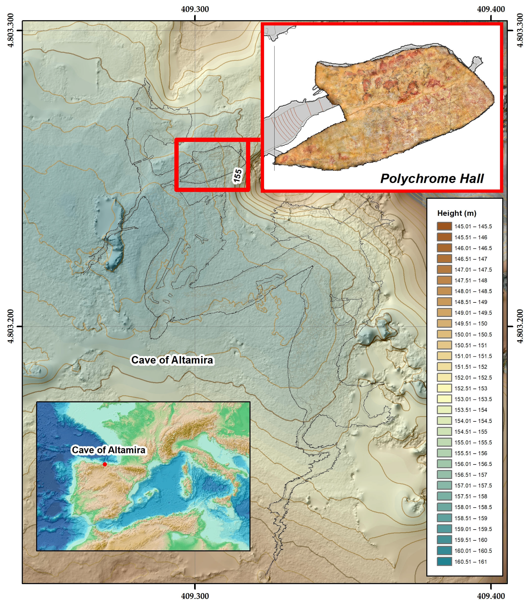
Figure 1. Location map of the Cave of Altamira: projection of the Cave of Altamira on the topographic surface, showing the Polychrome Hall and the orthoimage of its Ceiling.
Remotesensing 16 02099 g001
Figure 2. (a) Location of control area ALT1 in Polychrome Hall ceiling. The dashed white line indicates the position of the central fracture. (b) Picture of the general view of ALT1 study area. (c) Schematic stratigraphy of the Polychrome Hall ceiling according to [9,10,11], showing the depth range reached with the 1.6 GHz antenna in Polychrome Layer.
Remotesensing 16 02099 g002
Figure 3. (a) Control zone ALT1 and comparative pictures between (b) 2004 and (c) 2022 where migration and pigment dragging and pigment loss processes associated with drip points occur.
Remotesensing 16 02099 g003
Figure 4. General workflow scheme followed in this study.
Remotesensing 16 02099 g004
Figure 5. Photograph showing the device designed (a) in which the 1.6 GHz antenna was installed (b) with the odometer (c) maintaining a minimum distance in relation to the study area of the Polychrome Hall ceiling of 10 cm.
Remotesensing 16 02099 g005
Figure 6. Detail of the control area ALT1, with layout of the longitudinal and transverse profiles made in ALT1 and image of the field configuration.
Remotesensing 16 02099 g006
Figure 7. (a) Location of the ALT-1 active drip zone near the hind legs of the great bison figure. Drip points are indicated with blue polygons and streams with blue lines. The thicker the blue lines (streams), the higher the hierarchy in the ALT-1 active drip zone. (b) Active drip basins highlighted in green involved in the recorded pigment migrations in recent years. Black circles indicate areas of paint drop and loss and white circles indicate areas where pigment has been transported by the water film with no pigment fall recorded in recent years.
Remotesensing 16 02099 g007aRemotesensing 16 02099 g007b
Figure 8. Image showing the limestone rock stripped of paint due to the process of dragging and dripping of water. The white circle highlights a new drip that has already caused the loss of pigment adhesion to the supporting rock.
Remotesensing 16 02099 g008
Figure 9. (a) Reflection profile L5 (greyscale amplitudes) showing high-amplitude and strong reflections due to water, interpreted as the presence of moisture within the Polychrome Layer (highlighted in red rectangles: zones 1 and 6). (b) Areas of water/moisture: Superimposition of the sections of the first 36 cm. In blue the areas with higher presence and in white the areas with lower presence. (c) The 6 areas of high moisture mapped in the 3D isosurface model in ALT1 (highlighted with red numbers).
Remotesensing 16 02099 g009aRemotesensing 16 02099 g009b
Figure 10. (a) General view of the main surface fissures and fractures in the ALT-1 control area. (b) View of some of the small fissures or fractures that act as small contributions of moisture affecting, as highlighted in the box, the drip point ALT1_4. (c) Detail view of ALT1_4 control area.
Remotesensing 16 02099 g010
Figure 11. (a) Representation of hydrographic basins and active drip points over a wide surface of the Polychrome Hall ceiling. (b) 3D view showing the moisture distribution within the large central fracture and the control zone ALT1. It showcases the surface-level features like basins, streams, and drip points on the Ceiling area, with varying shades showing the degree of moisture accumulation. Lighter colors mean lower moisture accumulation, while blue indicates the highest accumulation of moisture. The green box highlights the internal moisture close to the Ceiling surface that is directly involved in the processes of paint carry-over, migration, and loss in the ALT1 control area.
Remotesensing 16 02099 g011
Figure 12. Location of the different witnesses located on the floor of the Polychrome Hall. Witness covering a series of drips located on the hump and head of one of the large polychrome bison.
Remotesensing 16 02099 g012
Figure 13. (a) Large central fracture sealed with cement mortar (indicated by the white arrow) and location of the nearby claviform signal (white box). (b) Drip point ALT1_1 and its associated main water inputs (blue arrows indicate the location and orientation of the marked water flows).
Remotesensing 16 02099 g013
Table 1. Comparison of parameters for the 400 MHz, 900 MHz, and 1.6 GHz antennas used on Polychrome Hall ceiling.
Frequency1.6 GHz900 MHz400 MHz
Frequency Range1.3–1.9 GHz600–1200 MHz250–600 MHz
Wavelength in Air (m)~0.1875~0.333~0.75
Wavelength (ε = 7.5) (m)~0.0684~0.1213~0.2732
Minimum Resolution (ε = 7.5) (m)~0.0342~0.0606~0.1366
Estimated Maximum Depth (ε = 7.5) N = 20 (m)~1.1 m~0.456 m1.026 m
Estimated Maximum Depth (ε = 7.5) N = 100 (m)~0.4 m~2.28 m~5.13 m
Vertical and Horizontal Resolution0.0342 m0.0606 m0.1366 m
Image Clarity (Entropy)0.8–1.00.5–0.80.2–0.5
Signal Attenuation High (50–70 dB) Moderate (30–50 dB) Low (20–30 dB)
Antenna Gain High (20–30 dB) Medium (10–20 dB) Low (0–10 dB)
Antenna Beamwidth 15° 25–30° 45–50°
Signal-to-Noise Ratio (SNR) 15 dB 12 dB 10 dB
Disclaimer/Publisher’s Note: The statements, opinions and data contained in all publications are solely those of the individual author(s) and contributor(s) and not of MDPI and/or the editor(s). MDPI and/or the editor(s) disclaim responsibility for any injury to people or property resulting from any ideas, methods, instructions or products referred to in the content.