Abstract
For synthetic aperture microwave radiometers, the problem of Radio Frequency Interference (RFI) is becoming more and more serious, which affects both the scientific retrieval of remote sensing data and the imaging quality of brightness temperature (BT) images. In the visibility data domain, the array factor synthesis algorithm is commonly employed to mitigate RFI sources and their Gibbs trailing. In the BT image domain, the CLEAN algorithm is typical applied to mitigate RFI sources and their Gibbs trailing. However, the array factor synthesis algorithm can result in anomalous BT points near the “zero trap” region, and the CLEAN algorithm will miss some BT points below a certain threshold. In this paper, a Bi-domain combined mitigation algorithm is proposed to mitigate RFI sources and their Gibbs trailing. Following initial mitigation in the visibility data domain, dual thresholds are applied to normalize anomalous BT points near the “zero trap” region, thereby enhancing imaging quality. The effectiveness of the Bi-domain combined mitigation algorithm is verified by using both measured data from SMOS L1A and simulated data. The experimental results demonstrate that the Bi-domain combined mitigation algorithm is superior to the array factor synthesis algorithm and the CLEAN algorithm in mitigating RFI sources and their Gibbs trailing.
1. Introduction
The L-band Interferometric Synthesis Aperture Radiometer system, with a Y-shaped antenna array, is widely used for Earth and ocean observations because of its high spatial resolution and wide field of view [1,2]. Two typical applications are the Microwave Imaging Radiometer using Aperture Synthesis (MIRAS) instrument carried by the Soil Moisture and Ocean Salinity (SMOS) satellite [3,4] launched by the European Space Agency and the payload interferometric microwave radiometer (IMR) onboard the Chinese Ocean Salinity Satellite [4,5]. The microwave radiation intensity of real objects will be submerged by RFI signals, thereby compromising or impeding the retrieval of geophysical parameters [6]. The impact of RFI has already been noted in the aforementioned two Earth observation applications, and it is anticipated that this impact will further exacerbate in the future. Hence, mitigating RFI in microwave radiation measurement applications is becoming increasingly urgent [7,8,9].
Several articles [10,11,12,13,14,15,16,17,18,19,20,21,22,23,24] have proposed solutions to mitigate RFI. In the visibility data domain, the array factor synthesis algorithm is commonly used to mitigate RFI, but it will produce anomalous BT points. In the BT image domain, the CLEAN algorithm and its derivative algorithms are commonly used RFI mitigation algorithms, but due to threshold settings, they may result in the omission of BT points below the threshold.
Based on this, this paper proposes a Bi-domain combined mitigation algorithm to mitigate RFI. This algorithm employs the array factor synthesis method in the visibility data domain for the first RFI mitigation, and then sets dual thresholds in the BT image domain to conduct a second mitigation for anomalous BT points appearing after the first RFI mitigation. In our experiments, both measured data and simulated data from SMOS L1A were utilized to validate the effectiveness of this algorithm. Simulation results indicate that the algorithm not only mitigates BT points below the threshold in the CLEAN algorithm but also resolves the issue of anomalous BT points near the “zero trap” region.
2. Basic Principles of Synthetic Aperture Radiometry
The basic unit of synthetic aperture radiometers is a binary interferometer, which makes multiple correlations between the output signals processed by the receiver (the output signals of two receiving channels of a baseline pair are directly correlated, which is called in-phase correlation; the correlation of one signal after a 90° phase shift is called orthogonal correlation; the combination of the two is a multiple correlation), and the visibility function covering different spatial frequencies from low to high could be obtained. Then, the image reconstruction of the BT distribution in the observation scene will be realized after error correction and inversion have been completed. The schematic diagram of its principle is shown in Figure 1.
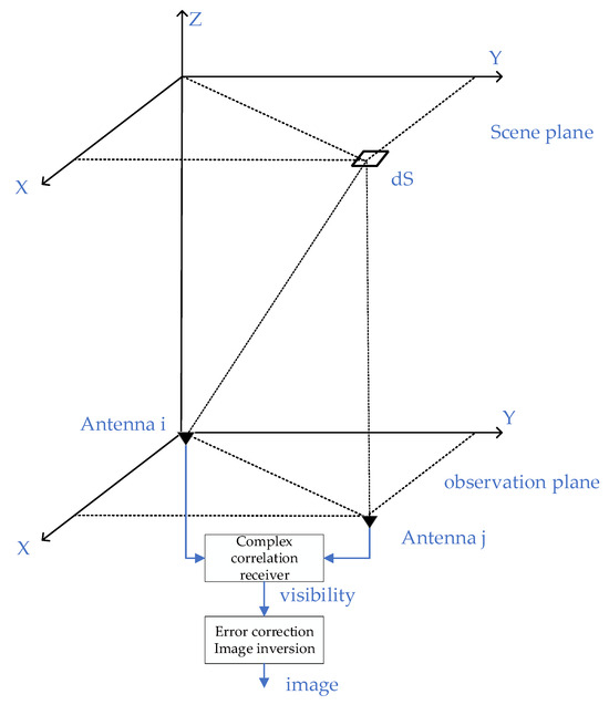
Figure 1.
A schematic diagram of the synthetic aperture interferometry imaging principle.
In particular, when the streak effect is ignored and the antenna pattern is consistent, the visibility function under the far field condition can be simplified as follows [25]:
where the BT distribution is defined as , and is the baseline coordinate of the antenna, , . That is, the visibility function obtained by the multiple correlation between the double antennas and the BT distribution is a standard Fourier transform.
The process of reconstructing the BT distribution of the original scene using the visibility function obtained by the operation from the baseline of the array antenna is called synthetic aperture imaging or inversion. According to the above equation, the BT distribution can be reversely obtained through the inverse Fourier transform of visibility function:
The inversion BT image can be derived from the above formula, but if there is RFI, the RFI source will produce interferences of varying degrees to the image. Generally, there will be a tailing phenomenon, also known as the Gibbs effect. The alleviation of the Gibbs phenomenon is a difficult problem in signal processing. Especially for the two-dimensional image domain, if the window function mitigation is directly added, the image resolution will be sacrificed, and the highest BT point cannot be eliminated. The same effect will be obtained by directly adding the window function to the visibility function. Therefore, we expect to introduce methods from the BT image domain and the visibility data domain to eliminate the highest BT point and its Gibbs effect without sacrificing resolution. In this paper, a Bi-domain combined mitigation algorithm is proposed to overcome the defects of the visibility data domain and the BT image domain mitigation algorithm.
3. The Bi-Domain Combined Mitigation Algorithm
3.1. The Establishment of the RFI Visibility Data Model
According to Equation (1), it is evident that the visibility function obtained through the double antenna cross-correlation technique can be Fourier-transformed using an estimated BT of the observed scene. Specifically, if the observed scene’s BT originates from a high-intensity point source at a specific location, , then the visibility function generated by this point source can be represented using the corresponding data model as follows:
According to Equation (3), an RFI point source traverses across various positions within the observed scene; its real and imaginary parts will exhibit periodic variations, manifesting interference fringes of brightness and darkness. Therefore, the antenna pair can be regarded as the fundamental binary interferometer. The Fourier relationship between the visibility data collected by the binary interferometer and the estimated BT of the observed scene suggests that the visibility data corresponding to the antenna pair can be viewed as samples of the estimated BT distribution in the spatial frequency domain ( domain).
3.2. The Establishment of the Visibility Data Model
Similarly, according to Equation (1), the visibility function corresponding to the scene can be represented as follows:
The visibility function with RFI can be represented as follows:
Li Jun and other related researchers proposed the array factor synthesis algorithm for mitigating RFI sources and their Gibbs trailing in the visibility data domain [15,16]. This algorithm adheres to the principle that the BT gain in the desired direction remains unchanged, and the gain at the “zero trap” region is set to the depth parameter of the nulls. However, anomalous BT points were produced near the “zero trap” region. The Bi-domain combined mitigation algorithm addresses this issue with improvements in this paper, as detailed in Section 3.3.
3.3. Bi-Domain Combined Mitigation Algorithm Overview
The core of the Bi-domain combined mitigation algorithm lies in the dual mitigation in both the visibility data domain and the BT image domain, weakening the adverse effects of RFI sources and their Gibbs trailing to restore the BT of the observed scene as much as possible. Next, a detailed analysis of the steps of the Bi-domain combined mitigation algorithm will be conducted.
Step 1. According to application requirements, select the appropriate size of the “zero trap” region and determine the appropriate null depth parameter .
It should be noted that the “zero trap” region is a constant, determined based on the positions of RFI points estimated in advance. In this paper, the RFI point and the six surrounding pixels are considered as the “zero trap” region. It is also worth noting that the choice of null depth is related to the power of interference: the greater the interference power, the deeper the required null. However, increasing the null depth also results in higher sidelobes. After comprehensive consideration, “zero” was selected as the null depth parameter.
Step 2. A certain desired direction of the inversion field of view is selected to solve the optimal weight vector . Taking the weight vector as the objective function, the quadratic programing symbolic math toolbox and MATLAB programing are used to effectively solve the optimal weight. The solution model is as follows:
where represents a binary norm of the optimal weight vector; represents a certain BT position of the field of view to be inversed; is the “zero trap” region required setting; and is the corresponding null depth parameter or null level. The equality constraint is to determine the BT gain of the equivalent array factor of the desired direction, while the inequality constraint aims to adjust the characteristic parameters, such as the “zero trap” region and null depth, so as to minimize final output RFI interference and brightness temperature noise power ratio (minimum dry noise ratio).
It should be noted that the desired direction refers to all areas within the field of view, excluding the “zero trap” region. By scanning these areas as desired directions, the entire inverted BT image can be obtained.
Step 3. The weighted summation of the obtained weight vector and the visibility function are used to obtain scene BT estimates for this desired direction .
where is the corresponding equivalent array factor; the sum of includes all the directions of the field of view; and the visibility data were obtained according to Section 3.1 and Section 3.2.
Step 4. The observation direction is constantly changed until the observation direction traverses the entire field of view (it is important to note that the observation direction should avoid the “zero trap” region to prevent conflicts that could affect the inversion results), and the optimal weight vector corresponding to each observation point in the field of view is determined while updating the observation direction. The inversion BT estimation for the entire field of view is obtained through the weighted summation of the weight vector and visibility function. Additionally, anomalous BT points may arise around the “zero trap” region.
Step 5. Find the peak value in the BT scenario ; it is presumed that values exceeding 350 K are regarded as RFI points. The peak point is then compared with the threshold of 350 K to ascertain whether it qualifies as an RFI point. If so, record the amplitude and position information of the RFI point . n represents the NTH RFI point, k represents the KTH cycle, and T represents the BT of the peak point.
Compute the mean BT of N pixel points surrounding the peak point, excluding the peak point .
Step 6. Compute the equivalent array factor for the position corresponding to the peak point .
where ; and represent the minimum sampling intervals along the and axes, respectively.
Step 7. Initialize the step factor using the average BT of the entire scene:
where represents the BT value of the BT estimation image, that is, the BT value obtained from Equation (7); denotes the total mean BT of the BT estimation image; and signifies the BT value of the anomalous points in the BT.
Step 8. The initialized step factor is used to mitigate the BT point. Following the mitigation process, the BT point, the average BT value, and the step factor will be updated in real time. This adaptive processing mechanism enables dynamic adjustments based on the evolving data, enhancing mitigation outcomes.
If , repeat Step 8 until the conditions are not met; then, repeat Step 5 until all the peak points are below the threshold of 350 K, where is a user-defined constant.
The aforementioned content delineates the pertinent theoretical framework of the Bi-domain combined mitigation algorithm. The program flowchart of the algorithm is illustrated in Figure 2 below.
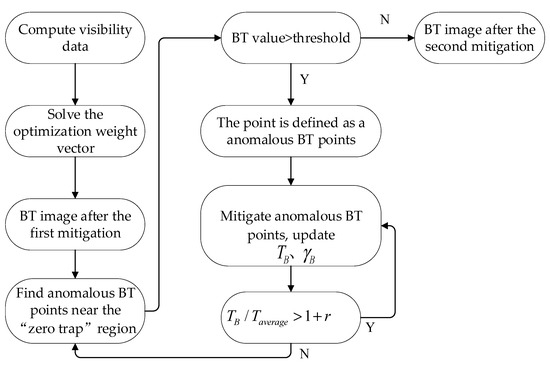
Figure 2.
The flowchart of the Bi-domain combined mitigation algorithm.
4. Data Simulation
In this section, the RFI mitigation algorithm introduced in Section 3 is simulated and analyzed. SMOS data from actual measurements are used to further confirm the effectiveness of the proposed algorithm, and the performance of this algorithm applied to SMOS satellite RFI interference mitigation is evaluated. The MIRAS payload on the SMOS satellite operates in the L band (1.404–1.423 GHz), with a center frequency of 1.4135 GHz. It adopts a Y-shaped array consisting of 69 antenna array elements distributed on three arms with an angle of 120°, and the antenna spacing is 0.875. Its U–V distribution is depicted in Figure 3a. All data points constitute a six-pointed star, which is not convenient for the periodic continuation of the Fourier transform during BT inversions. Therefore, it is considered to supplement the six-pointed star into a hexagon on the basis of it and fill in zeros where there are no data. In this manner, a set of points covering the entire U–V plane can be obtained through periodic continuation of the Fourier transform. Additionally, if zeros are continued to be filled in the outer ring of this hexagon, the resulting BT image will be smoother than the original image, while maintaining the same image resolution, as depicted in Figure 3b. The aforementioned zero-filling method ultimately presented the BT image of a hexagon, which is also the zero-filling method adopted in the simulation of this section.
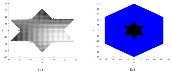
Figure 3.
U–V distribution of an antenna array of MIRAS carried by the SMOS satellite: (a) U–V distribution; (b) U–V distribution after zero-filling.
4.1. SMOS Data Introduction
ESA data are classified according to the processing stages of the signal processor, which are primarily divided into four levels, namely L1 data, L2 data, L3 data, and L4 data. L1 data consist of the elementary scientific data and are subdivided into three types: L1a, L1b, and L1c. L1a data are the visibility sampling data obtained between each antenna receiver prior to the applications of image reconstruction and full polarization, which can be used for simulation tests of the visibility data domain algorithm. L1b data are the output of SMOS observation and measurement after image reconstruction. They are composed of the Fourier component of the BT (also known as the apparent BT of the antenna interface) in the polarization reference coordinate frame of the antenna, making it suitable for simulation tests of the BT image domain. L1c data represent multi-incidence angle BT data at the top of the atmosphere, with each pixel stored in an equal-area grid system, providing information on each pixel. Users can also view the average BT at an incidence angle of 42.5° before downloading at the same time. Level L2 data comprise soil moisture and sea salinity data after processing; level L3 data contain daily sea wind speed data; and level L4 data include sea ice thickness data. This paper utilizes L1a data for validation analysis.
As SMOS no longer discloses the visibility sampling data, obtaining a significant amount of data for performance comparison and verification is unfeasible. The visibility data domain mitigation algorithm utilizing array factor synthesis may be affected, to some extent, by the lack of sampled measured data. Nevertheless, the visibility data belong to the original sampling data, and direct processing of the original visibility data will reduce systematic and environmental errors caused by the visibility function during the inversion process of BT image, as well as alleviate the Gibbs oscillation phenomenon induced by the truncation effect of the Fourier imaging. Inversely, it is easy to obtain the data in the BT image domain when it is in the open state, facilitating the visual assessment of RFI mitigation through the BT image domain data and enhancing the verification in terms of intuition and convenience. However, the data represent the Fourier spectrum component of the BT image reconstructed through L1a data inversion, external source correction, and error mitigation processing. It is important to note that the data provided by the government have not undergone processing by the standard external correction source, potentially being influenced by external factors such as the physical temperature of the receiver.
4.2. Simulation Verification of Simulation Data
Since obtaining real SMOS visibility data before and after the RFI source is closed is not feasible, quantitative analysis can only be conducted using simulation data. Qualitative analysis is conducted on the measured SMOS data of RFI pollution in the next section. This section will utilize simulation data to compare and analyze the array factor synthesis algorithm, the CLEAN algorithm, and the Bi-domain combined mitigation algorithm, and the specific data are utilized to assess the RFI mitigation’s effectiveness. This section outlines the land scene and the sea–land interface scene.
Figure 4 selects a land scene as the observation background, designed as a hexagonal field of view with simulated BT values of 290 K across the entire field of view. Different intensity RFI sources are added at the position (−0.4,0) within the field of view, with the Fourier imaging results depicted in Figure 4a,b. Figure 4a shows the BT distribution after adding a 2000 K RFI source to the land scene, and Figure 4b shows the BT distribution after adding a 5000 K RFI source. It is evident from these figures that the RFI sources and their Gibbs trailing significantly degrade the performance of the inversion images. Figure 4c,d illustrate the imaging results after applying the array factor synthesis algorithm for RFI mitigation. Figure 4e,f depict the imaging results after applying the CLEAN algorithm for RFI mitigation. Figure 4g,h show the imaging results after applying the Bi-domain combined mitigation algorithm for RFI mitigation.
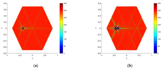
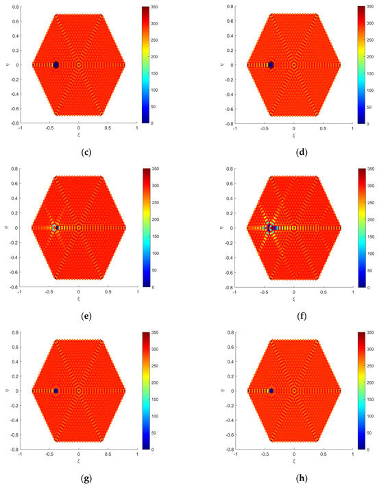
Figure 4.
Simulation data verification diagram in the land scene: (a) dirty image with a 2000 K RFI; (b) dirty image with a 5000 K RFI; (c) clean (a) applying the array factor synthesis algorithm; (d) clean (b) applying the array factor synthesis algorithm; (e) clean (a) applying the CLEAN algorithm; (f) clean (b) applying the CLEAN algorithm; (g) clean (a) applying the Bi-domain combined mitigation algorithm; (h) clean (b) applying the Bi-domain combined mitigation algorithm.
Figure 5 selects a sea–land interface scene as the observation background, designed as a hexagonal field of view, with position set to 290 K and position set to 120 K. Different intensity RFI sources are added at the position (−0.4,0) within the field of view, with the Fourier imaging results depicted in Figure 5a,b. Figure 5a shows the BT distribution after adding a 2000 K RFI source to the land scene, and Figure 5b shows the BT distribution after adding a 5000 K RFI source. It is evident from these figures that the RFI sources and their Gibbs trailing significantly degrade the performance of the inversion images. Figure 5c,d illustrate the imaging results after applying the array factor synthesis algorithm for RFI mitigation. Figure 5e,f depict the imaging results after applying the CLEAN algorithm for RFI mitigation. Figure 5g,h show the imaging results after applying the Bi-domain combined mitigation algorithm for RFI mitigation.
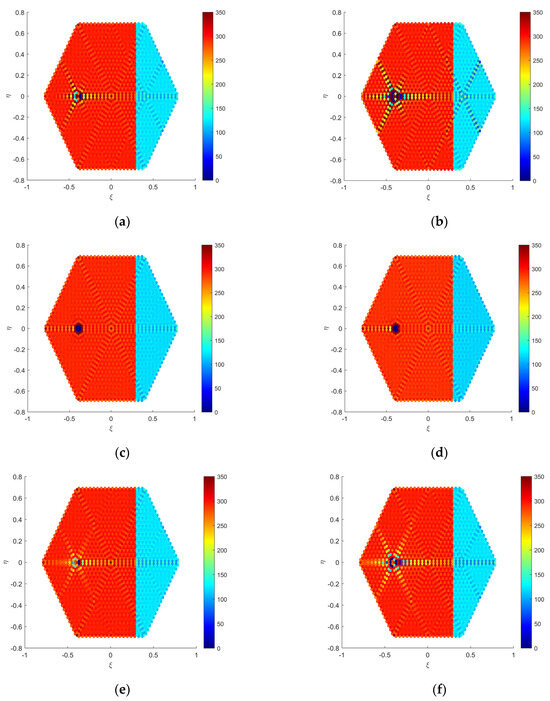
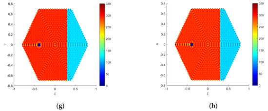
Figure 5.
Simulation data verification diagram in the sea–land interface scene: (a) dirty image with a 2000 K RFI; (b) dirty image with a 5000 K RFI; (c) clean (a) applying the array factor synthesis algorithm; (d) clean (b) applying the array factor synthesis algorithm; (e) clean (a) applying the CLEAN algorithm; (f) clean (b) applying the CLEAN algorithm; (g) clean (a) applying the Bi-domain combined mitigation algorithm; (h) clean (b) applying the Bi-domain combined mitigation algorithm.
To quantitatively assess the RFI mitigation efficacy of the Bi-domain combined mitigation algorithm, the Fourier imaging outcomes devoid of interference serve as the benchmark for comparison. The root mean square error between the RFI mitigation outcomes under interference conditions and the corresponding standard imaging results under ideal condition is defined as the interference residual. This is formulated as follows:
where represents the Fourier imaging result without added interference, serving as the reference standard for comparing interference mitigation performance. denotes the imaging results obtained through various mitigation algorithms after adding RFI, and N is the number of discrete pixels in the inversion imaging. Table 1 shows the quantitative calculation results of three algorithms.

Table 1.
The evaluation metrics of three algorithms in different scenes. (a) The evaluation metrics of three algorithms in the land scene. (b) The evaluation metrics of three algorithms in the sea–land interface scene.
This section verifies the rationality and effectiveness of the Bi-domain combined mitigation algorithm for mitigating RFI sources and their Gibbs trailing, and quantitatively assesses the mitigation performance of the algorithm in a simulated scene. The simulation results of two scenes with different intensities of RFI sources show that the Bi-domain combined mitigation algorithm not only outperforms the CLEAN algorithm but also effectively mitigates anomalous BT points caused the array factor synthesis algorithm, thereby enhancing image quality. The computed root mean square error further substantiates this conclusion. The “zero trap” region generated by the Bi-domain combined mitigation algorithm is a blank area, which can be adaptively filled with BT values based on the chosen scene in practical applications.
4.3. Simulation Verification of SMOS Actual Data
In this section, measured SMOS data are utilized to qualitatively assess the effectiveness of the Bi-domain combined mitigation algorithm. The unique identifier for this dataset is 199282533. The Fourier imaging result of the snapshot data is depicted in Figure 6a, revealing the significant degradation in inversion image performance due to the RFI source and its Gibbs trailing. Figure 6b illustrates the imaging result after applying the array factor synthesis algorithm for RFI mitigation. Figure 6c depicts the imaging result after applying the CLEAN algorithm for RFI mitigation. Figure 6d shows the imaging result after applying the Bi-domain combined mitigation algorithm for RFI mitigation. Figure 6e presents the BT distribution image obtained by subtracting Figure 6d from Figure 6b, demonstrating the mitigation advantages of the Bi-domain combined mitigation algorithm over the array factor synthesis algorithm. Figure 6f displays the BT distribution image obtained by subtracting Figure 6d from Figure 6c, illustrating the mitigation advantages of the Bi-domain combined mitigation algorithm over the CLEAN algorithm.
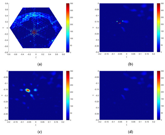
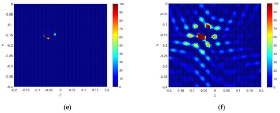
Figure 6.
SMOS actual data (ID199282533): (a) dirty imaging; (b) clean (a) applying the array factor synthesis algorithm; (c) clean (a) applying the CLEAN algorithm; (d) clean (a) applying the Bi-domain combined mitigation algorithm; (e) the difference between (b) and (d); (f) the difference between (c) and (d).
The unique identifier for this dataset is 199282415. The Fourier imaging result of the snapshot data is depicted in Figure 7a, revealing the significant degradation in inversion image performance due to the RFI source and its Gibbs trailing. Figure 7b illustrates the imaging result after applying the array factor synthesis algorithm for RFI mitigation. Figure 7c depicts the imaging result after applying the CLEAN algorithm for RFI mitigation. Figure 7d shows the imaging result after applying the Bi-domain combined mitigation algorithm for RFI mitigation. Figure 7e presents the BT distribution image obtained by subtracting Figure 7d from Figure 7b, demonstrating the mitigation advantages of the Bi-domain combined mitigation algorithm over the array factor synthesis algorithm. Figure 7f displays the BT distribution image obtained by subtracting Figure 7d from Figure 7c, illustrating the mitigation advantages of the Bi-domain combined mitigation algorithm over the CLEAN algorithm.
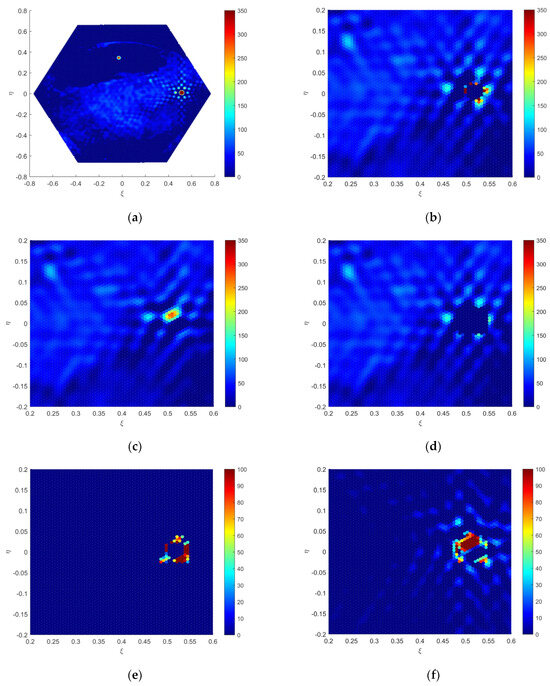
Figure 7.
SMOS actual data (ID199282415): (a) dirty imaging; (b) clean (a) applying the array factor synthesis algorithm; (c) clean (a) applying the CLEAN algorithm; (d) clean (a) applying the Bi-domain combined mitigation algorithm; (e) the difference between (b) and (d); (f) the difference between (c) and (d).
Through the imaging analysis, it is observed that the array factor synthesis algorithm can effectively mitigate the RFI source and its Gibbs trailing. However, it may result in anomalous BT points near the “zero trap” region. The CLEAN algorithm fails to mitigate BT points below a certain threshold. The Bi-domain combined mitigation algorithm initially mitigates the Gibbs effect in the visibility data domain using the array factor synthesis algorithm. Finally, by defining a threshold to mitigate anomalous BT points near the “zero trap” region, it compensates for the shortcomings of the array factor synthesis algorithm and the CLEAN algorithm, effectively mitigating the RFI source and its trailing. These results indicate that the proposed algorithm in this paper can mitigate anomalous BT points near the “zero trap” region caused by the array factor synthesis algorithm, thereby enhancing the imaging performance.
In this section, the rationality of employing the Bi-domain combined algorithm to mitigate the RFI and its trailing is verified, and the performance of this algorithm in SMOS RFI source mitigation is qualitatively assessed based on measured SMOS data. Consequently, the algorithm proposed in this paper can be directly applied to the SMOS system. It is important to note that the algorithm described in this paper necessitates the calculation of the inverse BT corresponding to each pixel to determine the optimal weight vector, thereby increasing the computational complexity to a certain extent.
5. Conclusions
This paper proposes a Bi-domain combined mitigation algorithm originating from the visibility data domain. The visibility data domain mitigation algorithms process raw data to fundamentally alleviate RFI sources and their Gibbs trailing, achieving superior mitigation effects compared to those in the BT image domain. However, traditional visibility data domain mitigation algorithms tend to produce anomalous BT points near the “zero trap” region. To address this question, the proposed algorithm in this paper introduces a threshold for a secondary mitigation of these anomalous points, which enhances the mitigation effect and improves image quality. The numerical results validate the effectiveness of this algorithm and imply the prospect of mitigating RFI sources and their Gibbs trailing. The disadvantage of this algorithm is that it results in a large computational burden. Future work will aim to develop a low-complexity algorithmic implementation. Moreover, this paper only discusses a single-point source. Mitigation algorithms for multiple RFI sources can also be explored in the future.
Author Contributions
Conceptualization, J.Z.; methodology, H.L. and L.Z.; software, H.L.; validation, H.L. and H.D.; data curation, H.L. and H.D.; writing—original draft preparation, H.L.; writing—review and editing, J.Z., H.L., Y.L., L.Z. and H.D.; project administration, J.Z.; funding acquisition, Y.L. All authors have read and agreed to the published version of the manuscript.
Funding
This research was supported by the Laboratory Stability Support Program (HTKJ2022KL504015).
Institutional Review Board Statement
Not applicable.
Informed Consent Statement
Not applicable.
Data Availability Statement
SMOS snapshot data were downloaded from the ESA accessed on 18 August 2013. (https://smos-diss.eo.esa.int/oads/access/collection).
Acknowledgments
We would like to thank Xian Institute of Space Radio Technology, Xi’an, China, for its contribution in providing the data.
Conflicts of Interest
The authors declare no conflicts of interest.
References
- Martàn-Neira, M.; LeVine, D.M.; Kerr, Y.; Skou, N.; Peichl, M.; Camps, A.; Corbella, I.; Hallikainen, M.; Font, J.; Wu, J.; et al. Microwave interferometric radiometry in remote sensing: An invited historical review. Radio Sci. 2014, 49, 415–449. [Google Scholar] [CrossRef]
- Le Vine, D.M.; Swift, C.T. Synthetic aperture radiometers for microwave remote sensing from space. In Proceedings of the 1996 International Geoscience and Remote Sensing Symposium (IGARSS’96), Lincoln, NE, USA, 27–31 May 1996; Volume 3, pp. 1547–1549. [Google Scholar]
- Kerr, Y.H.; Waldteufel, P.; Wigneron, J.-P.; Delwart, S.; Cabot, F.; Boutin, J.; Escorihuela, M.-J.; Font, J.; Reul, N.; Gruhier, C.; et al. The SMOS Mission: New Tool for Monitoring Key Elements of the Global Water Cycle. Proc. IEEE 2010, 98, 666–687. [Google Scholar] [CrossRef]
- Font, J.; Camps, A.; Borges, A.; Martín-Neira, M.; Boutin, J.; Reul, N.; Kerr, Y.H.; Hahne, A.; Mecklenburg, S. SMOS: The Challenging Sea Surface Salinity Measurement From Space. Proc. IEEE 2010, 98, 649–665. [Google Scholar] [CrossRef]
- Li, Y.; Yin, X.; Zhou, W.; Lin, M.; Liu, H.; Li, Y. Performance Simulation of the Payload IMR and MICAP Onboard the Chinese Ocean Salinity Satellite. IEEE Trans. Geosci. Remote Sens. 2021, 60, 5301916. [Google Scholar] [CrossRef]
- Njoku, E.G.; Ashcroft, P.; Chan, T.K.; Li, L. Global survey and statistics of radio-frequency interference in AMSR-E land observations. IEEE Trans. Geosci. Remote Sens. 2005, 43, 938–947. [Google Scholar] [CrossRef]
- Camps, A.; Vall-Llossera, M.; Duffo, N.; Zapata, M.; Corbella, I.; Torres, F.; Barrena, V. Sun effects in 2-D aperture synthesis radiometry imaging and their cancelation. IEEE Trans. Geosci. Remote Sens. 2004, 42, 1161–1167. [Google Scholar] [CrossRef]
- Corbella, I.; Martin-Neira, M.; Oliva, R.; Torres, F.; Duffo, N. Reduction of Secondary Lobes in Aperture Synthesis Radiometry. IEEE Geosci. Remote Sens. Lett. 2012, 9, 977–979. [Google Scholar] [CrossRef]
- Soldo, Y.; Khazaal, A.; Cabot, F.; Richaume, P.; Anterrieu, E.; Kerr, Y.H. Mitigation of RFIS for SMOS: A Distributed Approach. IEEE Trans. Geosci. Remote Sens. 2014, 52, 7470–7479. [Google Scholar] [CrossRef]
- Camps, A.; Gourrion, J.; Tarongi, J.M.; Llossera, M.V.; Gutierrez, A.; Barbosa, J.; Castro, R. Radio-Frequency interference detection and mitigation algorithms for synthetic Aperture Radiometers. Algorithms 2011, 4, 155–182. [Google Scholar] [CrossRef]
- Castro, R.; Gutierrez, A.; Barbosa, J. A First Set of Techniques to Detect Radio Frequency Interferences and Mitigate Their Impact on SMOS Data. IEEE Trans. Geosci. Remote Sens. 2012, 50, 1440–1447. [Google Scholar]
- Camps, A.; Park, H.; Gonzalez-Gambau, V. An imaging algorithm for synthetic aperture interferometric radiometers with built-in RFI mitigation. In Proceedings of the 2014 13th Specialist Meeting on Microwave Radiometry and Remote Sensing of the Environment (MicroRad), Pasadena, CA, USA, 24–27 March 2014; pp. 39–43. [Google Scholar]
- Park, H.; González-Gambau, V.; Camps, A.; Vall-Llossera, M. Improved MUSIC-Based SMOS RFI Source Detection and Geolocation Algorithm. IEEE Trans. Geosci. Remote Sens. 2016, 54, 1311–1322. [Google Scholar] [CrossRef]
- Peng, X.; Hu, F.; He, F.; Wu, L.; Li, J.; Zhu, D.; Liao, Z.; Qian, C. RFI mitigation of SMOS image based on CLEAN algorithm. In Proceedings of the 2016 IEEE International Geoscience and Remote Sensing Symposium (IGARSS), Beijing, China, 10–15 July 2016; pp. 816–819. [Google Scholar]
- Li, J.; Hu, F.; He, F.; Wu, L.; Peng, X. SMOS RFI mitigation using array factor synthesis of synthetic aperture interferometric radiometry. In Proceedings of the 2016 IEEE International Geoscience and Remote Sensing Symposium (IGARSS), Beijing, China, 10–15 July 2016; pp. 820–823. [Google Scholar]
- Li, J.; Hu, F.; He, F.; Wu, L.; Peng, X.; Zhu, D. An Imaging Method with Array Factor Synthesis in Synthetic Aperture Interferometric Radiometers. IEEE Geosci. Remote Sens. Lett. 2016, 13, 87–91. [Google Scholar]
- Hu, F.; Peng, X.; He, F.; Wu, L.; Li, J.; Cheng, Y.; Zhu, D. RFI Mitigation in Aperture Synthesis Radiometers Using a Modified CLEAN Algorithm. IEEE Geosci. Remote Sens. Lett. 2017, 14, 13–17. [Google Scholar] [CrossRef]
- Park, H.; Camps, A.; Vall-Llossera, M.; Gonzalez-Gambau, V. Strong RFI Impact Mitigation in the Synthetic Aperture Interferometric Radiometer. In Proceedings of the 2018 IEEE 15th Specialist Meeting on Microwave Radiometry and Remote Sensing of the Environment (MicroRad), Cambridge, MA, USA, 27–30 March 2018; pp. 1–4. [Google Scholar]
- Venkitasubramony, A.; Dai, E.; Gasiewski, A.; Stachura, M.; Elston, J. RFI Detection and Mitigation in an sUAS Based L Band Correlation Radiometer for Soil Moisture Measurements. In Proceedings of the 2019 RFI Workshop—Coexisting with Radio Frequency Interference (RFI), Toulouse, France, 23–26 September 2019; pp. 1–4. [Google Scholar]
- Buch, K.D. RFI Excision in Radiometers: A Radio Astronomy Perspective. In Proceedings of the IGARSS 2019—2019 IEEE International Geoscience and Remote Sensing Symposium, Yokohama, Japan, 28 July–2 August 2019; pp. 4535–4538. [Google Scholar]
- Jin, R.; Li, Q.; Liu, H. A Subspace Algorithm to Mitigate Energy Unknown RFI for Synthetic Aperture Interferometric Radiometer. IEEE Trans. Geosci. Remote Sens. 2020, 58, 227–237. [Google Scholar] [CrossRef]
- Lu, H.; Li, Y.; Yu, R.; Jin, A.; Lv, R.; Li, H.; Li, Q.; Zhu, D. An RFI Detection and Mitigation Algorithm for an L-Band Phased Array Radiometer. IEEE Geosci. Remote Sens. Lett. 2020, 17, 779–783. [Google Scholar] [CrossRef]
- Querol, J.; Camps, A.; Perez, A.; Oliva, R.; Onrubia, R.; Ramirez-Martinez, J.I.; Zurita, A.; Suess, M.; Martin-Neira, M. A Pre-Correlation RFI Mitigation Algorithm for L-Band Interferometric Radiometers. In Proceedings of the 2021 IEEE International Geoscience and Remote Sensing Symposium IGARSS, Brussels, Belgium, 11–16 July 2021; pp. 1819–1822. [Google Scholar]
- Li, Y.; Zhang, W.; Zhang, J.; Zhang, L. Improved CLEAN Algorithm for RFI Mitigation of Aperture Synthesis Radiometer Images. IEEE Geosci. Remote Sens. Lett. 2022, 19, 4018105. [Google Scholar] [CrossRef]
- Corbella, I.; Duffo, N.; Vall-Llossera, M.; Camps, A.; Torres, F. The visibility function in interferometric aperture synthesis radiometry. IEEE Trans. Geosci. Remote Sens. 2004, 42, 1677–1682. [Google Scholar] [CrossRef]
Disclaimer/Publisher’s Note: The statements, opinions and data contained in all publications are solely those of the individual author(s) and contributor(s) and not of MDPI and/or the editor(s). MDPI and/or the editor(s) disclaim responsibility for any injury to people or property resulting from any ideas, methods, instructions or products referred to in the content. |
© 2024 by the authors. Licensee MDPI, Basel, Switzerland. This article is an open access article distributed under the terms and conditions of the Creative Commons Attribution (CC BY) license (https://creativecommons.org/licenses/by/4.0/).