1. Introduction
Two-dimensional (2-D) radar is the earliest radar system, produced with the Second World War, which can provide the slant range and azimuth measurements of air targets. After years of development, 2-D radar technology has matured. Because of its small equipment, low cost, simplicity and reliability, it is still widely used in battlefield surveillance. However, due to the wide elevation dimension beam, the 2-D radar has poor resolution in the elevation dimension. In other words, it cannot effectively measure the elevation of air targets. Without elevation measurement, it is impossible to accurately locate the target, which will affect the intelligence quality. However, the high localization accuracy of the target is significant in modern warfare. Therefore, the target three-dimensional localization for 2-D radar is one of the difficult problems to be solved urgently.
Currently, three classes of methods have been proposed to achieve 2-D radar elevation estimation. The first method is that 2-D radar usually needs to be fused with other sensor data to provide accurate elevation information. Take Height Finder Radar (HFR) aided 2-D radar as an example. Due to the advanced development and maturity of 2-D radar technology, the utilization of 2-D radar for target azimuth and range measurement, along with the HFR for precise height measurement, offers significant technical advantages including high accuracy, robust anti-interference capability, and easy implementation, which has been widely used in the air defense system. However, equipping the radar with dedicated sensors not only increases the cost of the radar but also complicates the measurement process and increases the processing of intelligence data. Therefore, the real-time performance of this method is poor, and it is not conducive to the maneuverability of the radar position. Secondly, a single 2-D radar can estimate the target height by using the Doppler history of the target over several scans, since the rate of the Doppler frequency changes depends on the target height. In Ref. [
1], the changing rate of the radial velocity is estimated by Radon transform, and it is used to calculate the target height with the estimated radial velocity and the target measurements of 2-D radar. However, target echoes over multiple scans are used here, and it is assumed that the target position and velocity remain unchanged during these scanning intervals. Therefore, the method is not suitable for high-speed moving or maneuvering targets. In addition, there is a certain delay in obtaining the target height information. Thirdly, with the continuous development of radar networking technology in recent years, it has become a new way to estimate the target elevation by using the redundant information of the radar network consisting of multiple 2-D radar stations. The target elevation or altitude can be estimated by using the single point tracking initialization algorithm with the range and azimuth measurements of the target obtained in multiple 2-D radars [
2,
3]. The measurements from multiple observation angles need to be combined and fused; therefore, the estimation accuracy depends on the number and the distribution of multiple 2-D radar stations. However, high-precision spatial–temporal registration is the premise of networking, and the cooperative estimation in the fusion center will also inevitably bring time delay. Moreover, in the electronic countermeasure scene, the conditions required for radar cooperation in networking are difficult to meet, and even if they are met, networking is always at risk of being destroyed.
Based on the analysis of available methods, the target three-dimensional localization algorithm for 2-D radar with low cost and low delay is still worthy of further study. The Reconfigurable Intelligent Surface (RIS), which has been widely used in the field of wireless communication, provides the possibility for developing a novel three-dimensional localization method for 2-D radar based on its characteristic of reconstructing signal propagation. The RIS is a planar array consisting of many low-cost passive or active reflecting elements, which are each capable of independently controlling controllable amplitude and/or phase changes in the incident signal. As a nearly passive low-cost planar structure, the RIS can be easily deployed to realize smart radio environments [
4,
5]. Compared with the dedicated altimeter radar or the construction of multi-station radar networking, the RIS has low power consumption and low cost. It can not only move at any time by Unmanned Aerial Vehicle (UAV) but also change the propagation direction of electromagnetic waves through phase shifts. Then, the radar can receive the target echo signal, and it does not require data transmission of fusion information, which will improve the real-time performance. In addition, it is easier to achieve high-precision alignment for the RIS-assisted radar system.
At the earliest time, the RIS was used in the field of wireless communication. It can realize directional transmission and the reception of wireless signals by dynamically adjusting the phase and amplitude of its surface elements, improving the transmission efficiency of signals and the overall performance of the network [
6]. In addition, the RIS is used to adaptively adjust the propagation path and phase of signals according to the real-time changes of wireless channels, thus effectively resisting multipath fading and interference and reducing the bit error rate [
7]. In Ref. [
8], the transmission rate has been improved by using the RIS to realize the real-time adjustment and optimization of wireless signals. The RIS-assisted channel estimation technology can improve the accuracy and efficiency of channel estimation by using its dynamic control ability on wireless signals [
9,
10,
11]. In Ref. [
12], the RIS was used as a measuring device to monitor and feedback the propagation characteristics and path loss of wireless signals in real time, which provides an important basis for the design and optimization of wireless communication systems. The RIS has also been widely used in mobile networks and intelligent transportation [
13,
14], since it can dynamically adjust and control wireless signals to achieve the accurate localization of users. In addition, the RIS has been successfully applied to dual-function radar communication systems [
15,
16], which can realize radar detection and communication functions at the same time. In the radar mode, the RIS is used to control the propagation direction of electromagnetic waves and improve the performance of the radar system. In the communication mode, the RIS is used to realize the transmission and reception of signals and improve the performance of the communication system [
17,
18,
19,
20].
The excellent characteristics of the RIS in changing the propagation direction of electromagnetic waves should be able to provide additional receiving channels for the radar, which is a research direction with great application prospects. The RIS has been applied to radar systems, which helps the radar improve its performance in many ways. Buzzi and Grossi incorporated the radar system with the RIS technique to improve the target detection performance [
21,
22,
23]. Then, the RIS-assisted MIMO radar [
24,
25] and the multi-target detection application [
26] are considered, in which the detection performance is improved by jointly optimizing both radar waveforms and the RIS phase shifts. The author in [
27] introduced the RISs to extend the radar surveillance in non-line-of-sight (N-LOS) scenarios. In addition, the RIS has been used to improve the accuracy of target measurement by controlling the propagation direction of electromagnetic waves. By analyzing the received electromagnetic wave signal, the position of the target can be determined, and its accurate tracking can be realized [
28,
29]. In Ref. [
30], the parameters of the target, such as size and shape, were estimated by analyzing the received electromagnetic wave signal in the RIS-assisted radar.
Inspired by the excellent application of RISs in radar measurement, this paper introduces one or more RISs in the wide receiving beam of the 2-D radar to realize the three-dimensional localization of the target. In the RIS-assisted 2-D radar system, the redundant target measurements in the RIS-assisted channels are used to estimate the three-dimensional coordinates of the target with the radar measurements by solving a least square problem with the convex optimization method. The Cramer–Rao Lower Bound (CRLB) is derived to measure the localization accuracy [
31], and the effectiveness of the proposed method is verified by the simulation results.
The rest of the paper is organized as follows. In
Section 2, the constructed signal model of RIS-assisted 2-D radar is presented. In
Section 3, the three-dimensional localization algorithm is proposed based on the radar measurements, and its CRLB is derived to measure the target localization accuracy. In
Section 4, the simulation analysis of the RIS-assisted 2-D radar localization algorithm is studied. The conclusion is given in
Section 5.
2. System Model
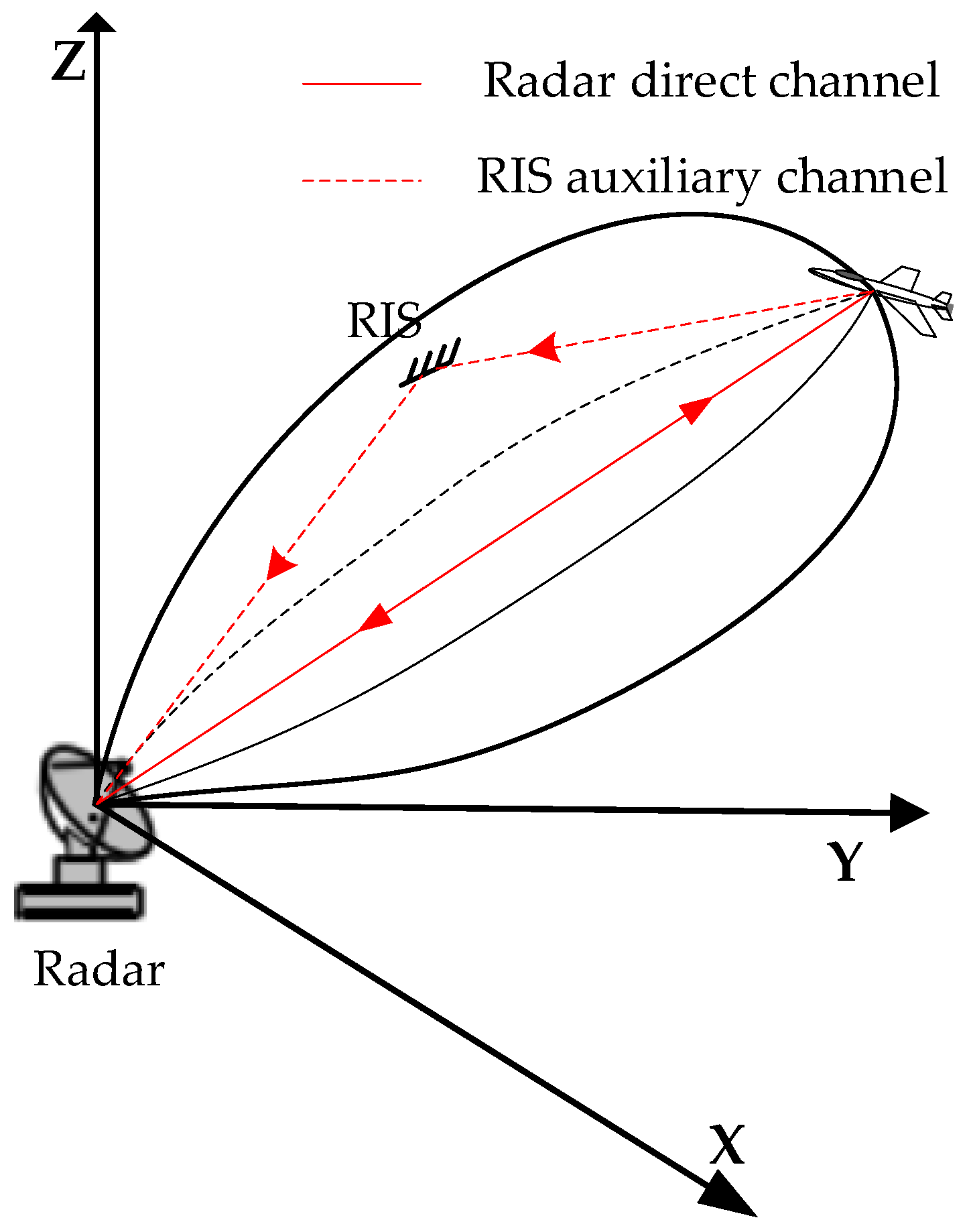
The target three-dimensional localization with the RIS-assisted 2-D radar is considered. As shown in
Figure 1, a single RIS-assisted 2-D radar is given as an example, which is built with a single-station 2-D radar and an RIS. The 2-D radar can only measure the distance from the target to the radar and the azimuth of the target relative to the radar, but it cannot measure the elevation of the target. The detection beam of 2-D radar is usually narrow in the azimuth dimension to achieve high azimuth resolution but wide in elevation dimension to receive the target echoes from different elevations. Taking advantage of the wide beam in the elevation dimension, several UAVs carrying RISs are set in the receiving beam to form multiple auxiliary measurement channels. Hence, an RIS-assisted 2-D radar is constructed to realize target three-dimensional localization.
The RISs are mounted on the UAVs and stay in the radar detection beam when the radar is scanning the beam. Different from the conventional radar beam scanning for target detection, the spatial scanning in the RIS-assisted 2-D radar system is accomplished by the joint scanning of the radar beam and the RIS receiving beam. When the radar scans the area of interest, the receiving beam of the RIS should scan all the area covered by the radar beam, and the transmitting beam of the RIS should be always pointed at the radar. Therefore, the radar can receive the target direct echo and the target echo signal reflected by the RISs. The radar transmitting beam points to the detection target, and the received target echo signal includes two parts. The first one is the radar direct receiving channel—the echo from the target directly to the radar, which is called the “radar direct channel”. The other one is the RIS-assisted receiving channel—the echo signal from the target to the RIS and then reflected from the RIS to the radar receiving channel, which is called the “RIS auxiliary channel”. In the RIS-assisted 2-D radar, the received and reflected beams of the RIS should be controlled by adjusting the phases of the RIS reflectors. The received beam of the RIS should point to the detected target, and the reflected beam of the RIS should point to the radar. In addition, to ensure enough observation angle difference in different measurement channels, the distribution of RISs is relatively dispersed, and the observation angle is different from that of the radar direct channel.
Suppose that there are K targets in the detection beam of 2-D radar. The locations of the radar are , and the coordinate of the k-th target is . M auxiliary RISs carried by the UAVs follow the scanning beam of the 2-D radar. The locations of the m-th RIS are , . Since the RISs need to communicate with the 2-D radar, they are usually much closer to the radar than the target. The arrival time of one target in different channels is close on the time axis, forming a time series. In the scenario of sparse multi-targets, it is assumed that the time series of different targets do not overlap on the time axis.
The target echo
received by the radar is divided into the direct channel echo
and the auxiliary channel echo
:
In the radar direct channel, the target echo
can be written as
where
is the amplitude of the
k-th target.
is the radar transmitted signal.
refers to the time delay.
represents the distance from the
k-th target to the radar.
is the speed of light, and
m/s.
is the channel noise following the Gaussian distribution.
For the 2-D radar, the range and azimuth angle of the
k-th target can be measured, which are assumed as
and
,
where
The measurement noise
and
obey the normal distribution with zero mean, i.e.,
,
.
and
represent the range and azimuth measurement errors of the 2-D radar, which is determined by the Signal-to-Noise Ratio (SNR) of the
k-th target in the target echo
,
where
B is the bandwidth, and
is the 3 dB beam width in the azimuth dimension.
In the
m-th auxiliary channel, the target echo
is
is the Gaussian noise, which is independent from
.
is the echo of the
k-th target is received in the
m-th auxiliary channel,
where
is the amplitude of the
k-th target of the
m-th RIS.
and
are the target phase vectors of the target-RIS and the RIS-radar channels, respectively.
L is the number of sub-
-sized surface element of the RIS.
is the adjustable phase matrix of the
m-th RIS.
refers to the time delay of the
k-th target in the
m-th RIS-assisted auxiliary channel.
stands for the matrix transpose.
represents a diagonal matrix with the elements of the vector as its diagonal elements.
Based on the maximum SNR criterion, the phase matrix
for the under-test resolution cell should be set as
Clearly, , and the phase of the l-th element in the m-th RIS is , .
Since the distances between the radar and the RISs are known, the measured range sum
in the
m-th auxiliary channel represents the total range from the radar to the
k-th target and then to the
m-th RIS, which can be written as
where
represents the distance from the
k-th target to the
m-th RIS,
The measurement noise
, and
where
represents the SNR of the
k-th target in the
m-th auxiliary channel. According to the relative position relationship between the RIS and the 2-D radar,
can be expressed with the SNR of the direct channel
,
.
represents the distance from the
m-th RIS to radar.
As shown in (1), the target echo in the direct channel and all the auxiliary channels are added in the target echo in the 2-D radar. One target will appear M + 1 times in the radar echo, resulting in M + 1 measurements under the assumption that the detection probability is 1. By designing a specific coding sequence for each RIS, which can be identified in the radar echo, the target measurements in different channels can be identified. Therefore, for each target to be localized, its measurements in M + 1 channels can be obtained, and they are combined to realize the three-dimensional target localization.
3. Three-Dimensional Target Localization
3.1. Localization Method
In this section, the measurements and in the direct channel and , m = 1, 2, …, M in the auxiliary channels are combined to estimate the three-dimensional location of the k-th target.
It is assumed that the estimated location of the
k-th target is represented as
. According to (3) and (11), the range measurements
in the direct channel and
in the auxiliary channels are the sum of their true values and measurement errors. Based on the criterion of Minimum Mean Square Error (MMSE), the estimation of the target location
can be established as a least squares problem,
where
The relationships between the distance , and the target location are given in (5) and (12).
Considering the azimuth
of the
k-th target in the direct channel, the following constraints can be obtained,
where
is determined by the azimuth error
in (7). With the confidence interval set as 99.7%,
.
Although the target pitch is not known in 2-D radar, its sine and cosine values must be less than 1. Therefore, the upper limit of the X-axis and Y-axis coordinates of the target can be obtained as shown in (17) and (18),
where
is also determined by the range error of 2-D radar. Herein,
. The
and
in (17) and (18) are considered to make the upper limit as large as possible, and the probability of the X-axis and Y-axis coordinates of the
k-th target exceeding the set upper limit is extremely small.
There is certain restriction on the flying height of aircrafts; it is reasonably assumed that the height of aircraft
is usually less than 20 km,
Therefore, the target three-dimensional localization can be formulated as the following optimization problem,
where
represents the three-dimensional detection space where the target may exist.
The optimization problem in (20) is convex, which will be proved, and then the convex optimization method is used to find its minimum value.
Firstly, it is proved that the optimization function is convex. Since and are both square roots of Euclidean distance, they are both convex functions about . As shown in (15), is the sum of several square terms, and each square term is a convex function. Therefore, is also a convex function.
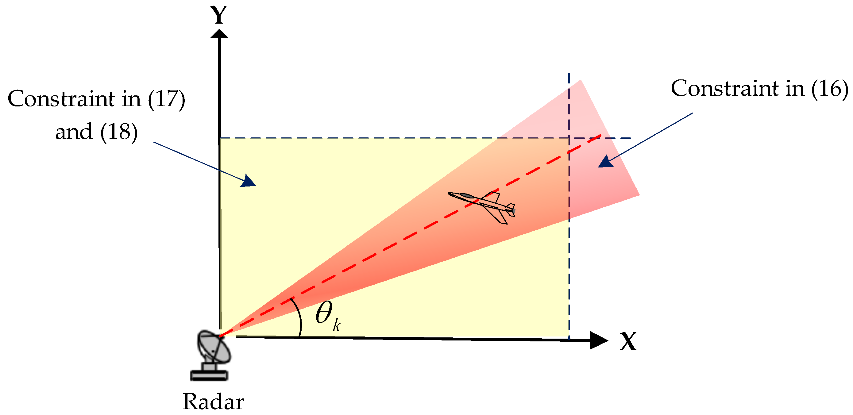
Then, it is proved that the constraint set is a convex set. As shown in
Figure 2, the constraint (16) depicts that the
k-th target is located in a fan-shaped area where the measured azimuth angle
is the central angle and the incremental angle around
is
. In addition, the constraint in (17) and (18) represents a rectangular area, which is also a convex set. Therefore, the overlapping area of these two convex sets is still a convex set, as shown by the shaded area in
Figure 2.
Since the optimization problem (20) for localization is convex, the convex optimization method is available to find its optimal solution, and the three-dimensional localization of the targets can be obtained in the RIS-assisted 2-D radar.
The methods to solve convex functions include the gradient descent method, conjugate gradient method, Newton method, quasi-Newton method, interior point method and simplex method. There are also some special libraries and toolkits, such as CVXPY, MOSEK, Gurobi, SCIP and MATLAB optimization toolkits, which can be used to solve convex optimization problems. For the analysis of computational complexity, the interior point method is taken as an example, which is a classical algorithm for solving convex optimization problems. The computational complexity of the interior point method is usually O(N3), where N is the number of unknowns. The target localization problem in this paper is a small-scale problem, N = 3, and therefore, this complexity is completely acceptable.
3.2. CRLB
The CRLB is widely used in signal detection and estimation to provide a lower bound for the variance of any unbiased parameter estimator. In this section, the CRLB is derived to measure the target localization accuracy for the proposed localization algorithm. Its Mean Square Error (MSE) or Root Mean Square Error (RMSE) can be compared with the CRLB, and the performance gap between the algorithm and the best performance will be known.
It is assumed that
M RISs are used to assist the 2-D radar. Let the position of the
k-th target be
. The measurement in the direct channel and the auxiliary channels for the
k-th target can be written as
The
k-th target measurement equation can be expressed as
where
Thus, the likelihood function of vector
can be expressed as
Let
where
represents the
i-th element in
, and
represents the
i-th element in
.
The likelihood function satisfies the regularity condition for each argument, i.e.,
For each unbiased estimate of the variance of
, there exists a lower bound, which can be expressed as
This lower bound is referred to as the CRLB lower bound of the unbiased estimator, where
is the Fisher information matrix with the dimension as
, and each element of the matrix is defined,
where
,
,
. Since it is complicated to directly differentiate
with respect to
, the Fisher matrix of
is firstly obtained,
According to the chain rule, the Fisher information matrix
can be derived as
where
and
The lower bound
of
can be obtained by inverting
,
Among them, the main diagonal element of
is the CRLB on the
X-axis,
Y-axis and Z-axis, respectively, and the CRLB of the localization accuracy of the whole system can be obtained as
The CRLB is a theoretical limit to measure the estimation accuracy, which gives the minimum possible value of the estimation error considering all possible observations and target parameter estimation methods. This is a very important performance metric because it reveals the optimal performance that can be achieved by the estimation problem with the given observations.
For the RIS-assisted 2-D radar to locate targets, by studying the CRLB of the localization system, a more comprehensive understanding of the system performance in practice can be obtained. In addition, the CRLB helps to deeply understand the advantages of this method to further optimize the system design and improve the overall performance of the RIS-assisted 2-D radar system.
4. Simulation Analysis
The target localization algorithm is simulated with an RIS-assisted 2-D radar, and the localization accuracy is measured by the Geometric Dilution of Precision (GDOP) [
32,
33], which is an index to measure the geometric accuracy of the localization system and represents the localization accuracy of the target in different directions. The smaller the target localization error, the lower the GDOP and the higher the localization accuracy. The fmincon function in the optimization toolbox of the MATLAB is used to solve the proposed convex optimization problem in (20).
Firstly, a 2-D radar assisted by three RISs is simulated to indicate the feasibility and effectiveness of the localization algorithm, and the estimated GDOP versus the target SNR is simulated and compared with the derived CRLB in (38). Secondly, the localization GDOP and the CRLB of the target at different positions are covered. Thirdly, in the case of different RIS numbers and station layouts, the localization algorithm is simulated to demonstrate the influence of the RIS number and station layout on the GDOP. Fourthly, the localization results in a multi-target scenario are given. Finally, the influence of the site errors of the RISs is considered.
4.1. Localization Accuracy Simulation
A 2-D radar assisted by three RISs carried by UAVs are considered. The 2-D radar is located at [0, 0, 0] km. The location of the target to be located is [24, 48, 12] km. The locations of three RISs are [1.34, 2.68, 0.1] km, [1.34, 2.68, 1.3] km and [1.34, 2.68, 2.5] km. The azimuth angles of the targets and RISs are almost the same to ensure that RISs and targets are always in the beam of 2-D radar. The radar has a bandwidth of 5 MHz and a beam width of .
Since the localization accuracy depends on the radar measurement error, which is determined by the SNR of the received target echoes, the first target is selected as a reference, and it is assumed that its SNR in the direct channel is set to change from 5 to 30 dB. The target SNR in the auxiliary channels can be deduced according to the basic radar equation.
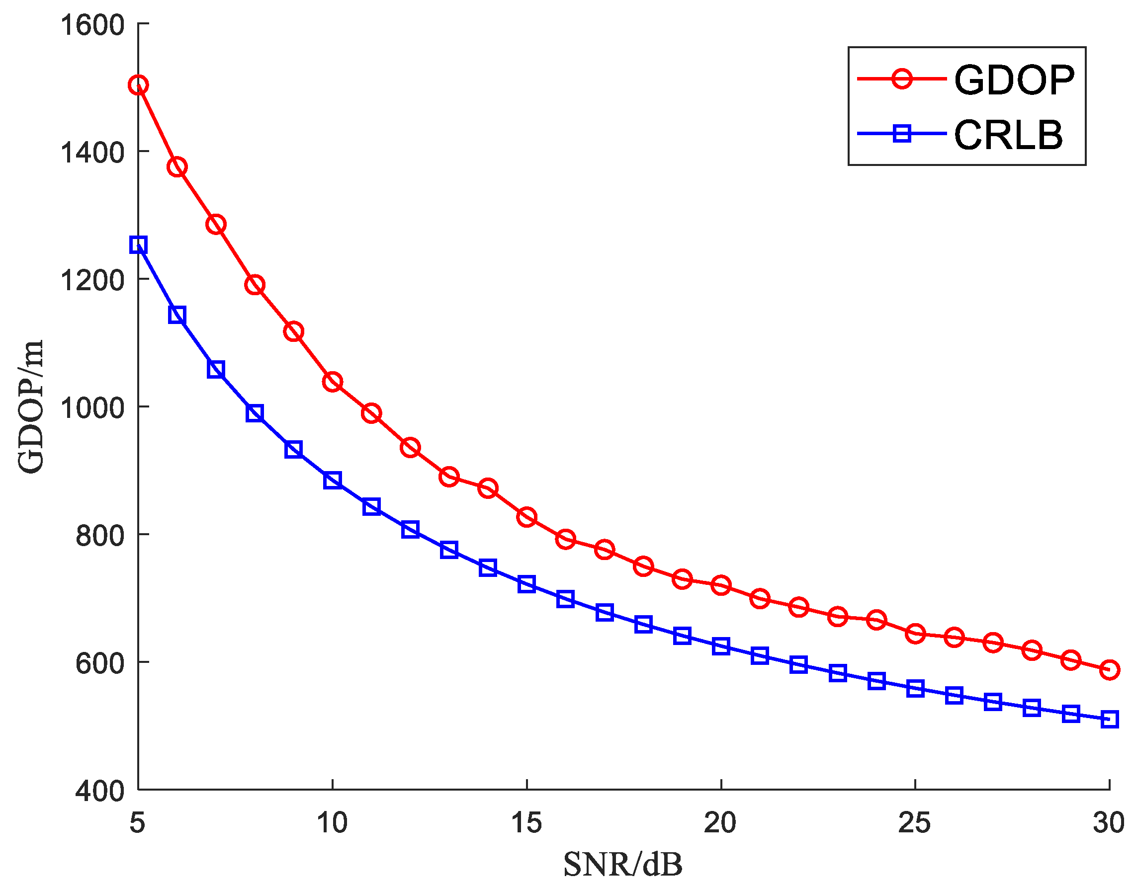
As shown in
Figure 3, the estimated GDOP by averaging 5000 Monto Carlo simulation results is reported, in which the CRLB for different values of the SNR is also calculated and plotted.
It can be seen from
Figure 3 that the proposed algorithm can achieve effective target localization in the RIS-assisted 2-D radar, and the GDOP is lower than 800 m when the target SNR is higher than 13 dB. In addition, the localization accuracy becomes higher with the increase of the target SNR, since the larger SNR will improve the target measurement accuracy in direct and auxiliary channels, thus improving the target localization accuracy of the proposed RIS-assisted radar system. Compared with the calculated CRLB, the estimated GDOP is slightly higher and closer to the CRLB, and their difference becomes smaller with the increase of SNR. It is indicated that the accuracy of the radar localization system is closer to the best possible accuracy.
4.2. Influence of Target Location on Localization Accuracy
Since the target location affects the localization accuracy, the GDOP for different target locations is simulated in the single target scenario. The height of the target is fixed at 9 km, and the X-axis and Y-axis of the target change from 20 to 80 km in steps of 4 km. The remainder of the simulation parameters of the RIS-assisted 2-D radar are the same as in
Section 4.1.
When the target is located at [20, 40, 9] km, the SNR of the direct channel is 30 dB, and the coordinates of the RISs are [1.34, 2.68, 0.1] km, [1.34, 2.68, 0.8] km and [1.34, 2.68, 1.5] km respectively. For the other target locations, the target SNR can be calculated by proportional calculation. To ensure that three assisted RISs always stay in the radar detection beam, they are mounted on the UAVs and move with the scanning beam. The relative locations of the target and the RISs with the 2-D radar remain unchanged.
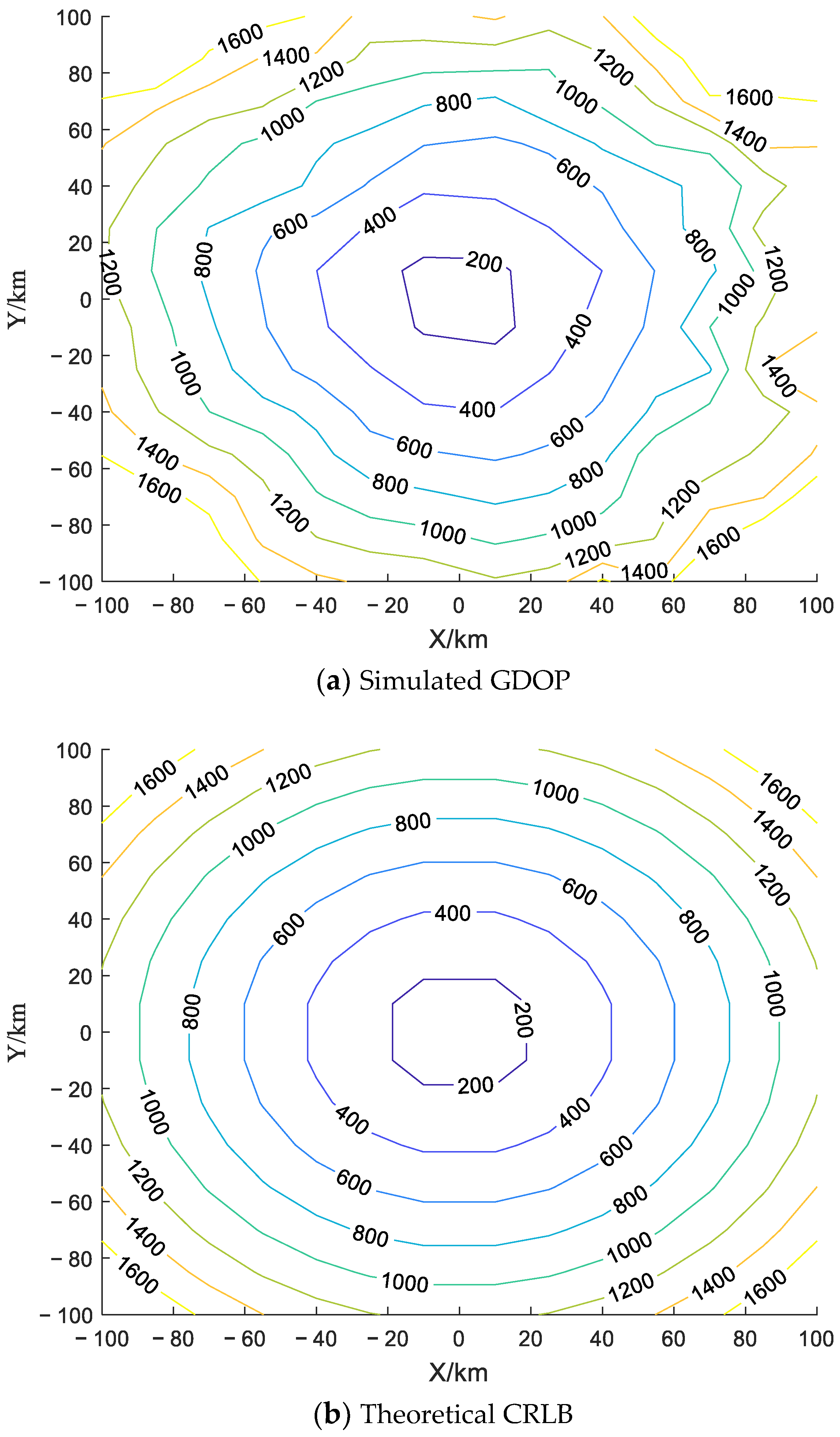
For each target located in the detection area of
km, the estimated GDOP are obtained by Monto Carlo simulation with 5000 run times. The simulation results are given in
Figure 4a. The derived CRLB in (38) is also calculated in
Figure 4b as the theoretical estimation accuracy limit, and the differences between the simulated GDOP and the CRLB are shown in
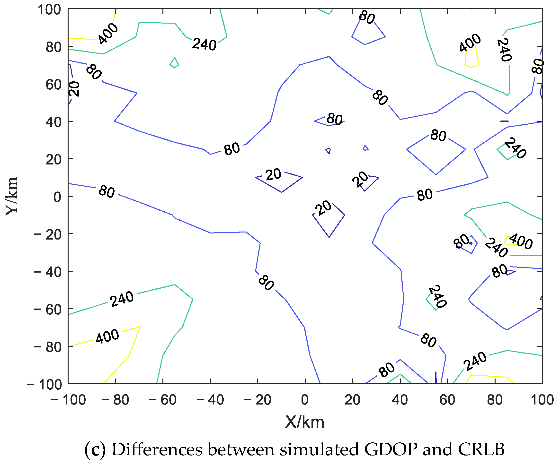
Figure 4c.
As shown in
Figure 4a,b, the closer the target is to the radar, the smaller the GDOP is. It is indicated that the localization accuracy becomes lower when the target becomes further away from the 2-D radar. When the distance between the target and the radar increases, the target SNR will become lower, resulting in the deterioration of target localization estimation accuracy. In addition, the differences between the simulated GDOP and the CRLB, shown in
Figure 4c, become smaller when the target becomes closer to the radar. The simulation result is consistent with the conclusion of
Figure 3.
4.3. Influence of the Number and Station Layout of RISs on Localization Accuracy
Firstly, the influence of the number of RISs on the localization accuracy is discussed. A 2-D radar located at [0, 0, 0] km is assisted by several RISs to locate one target with its location as [20, 40, 9] km. Up to four RISs are used here, and their locations are [1.34, 2.68, 0.1] km, [1.34, 2.68, 1.3] km, [1.34, 2.68, 2.5] km and [1.34, 2.68, 3.7] km. When the first
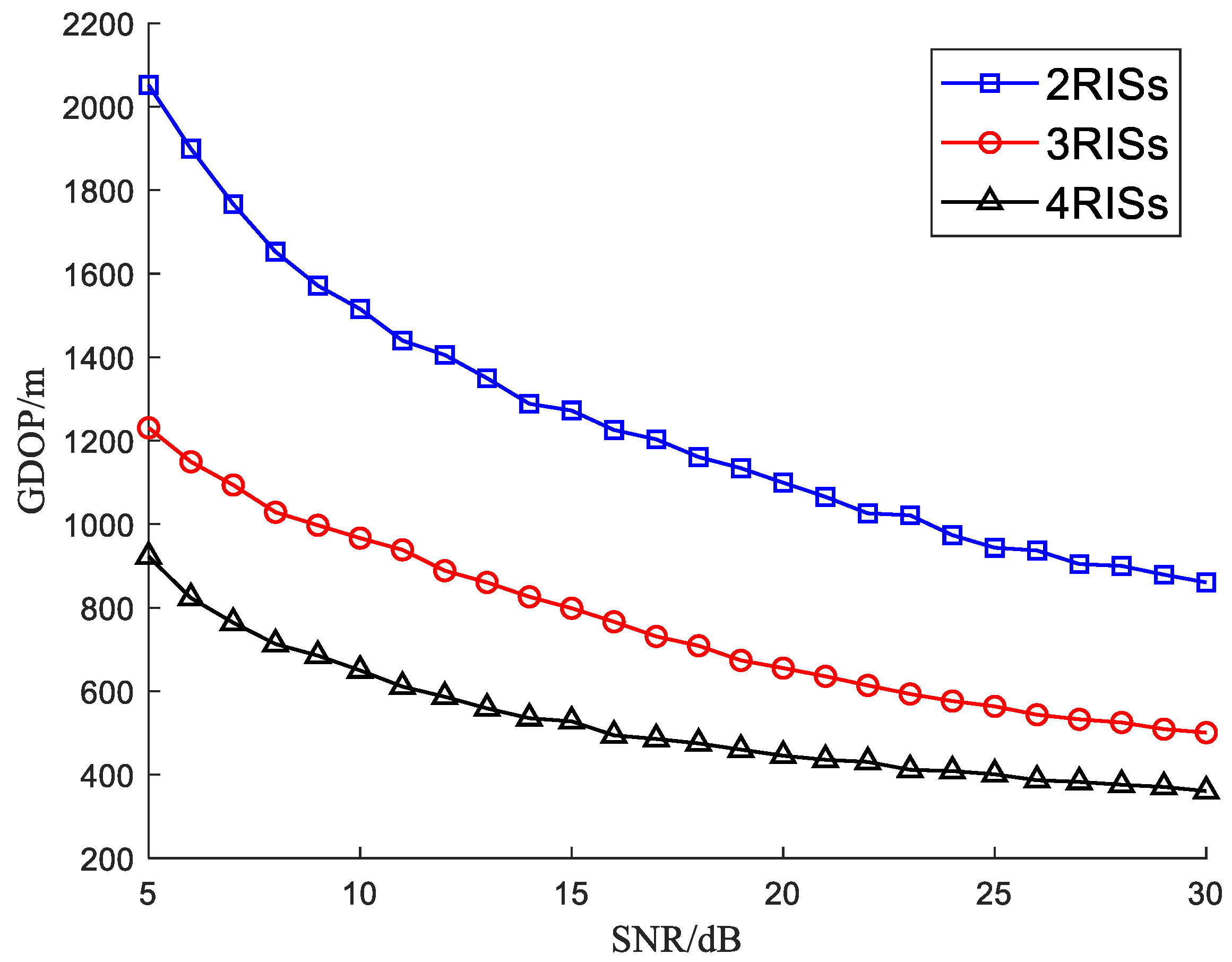
RISs are used to assist the 2-D radar, the localization accuracy can be simulated as shown in
Figure 5, where three curves give the simulated GDOP with different numbers of RISs as
. The GDOP is obtained with 5000 Monte Carlo simulation experiments.
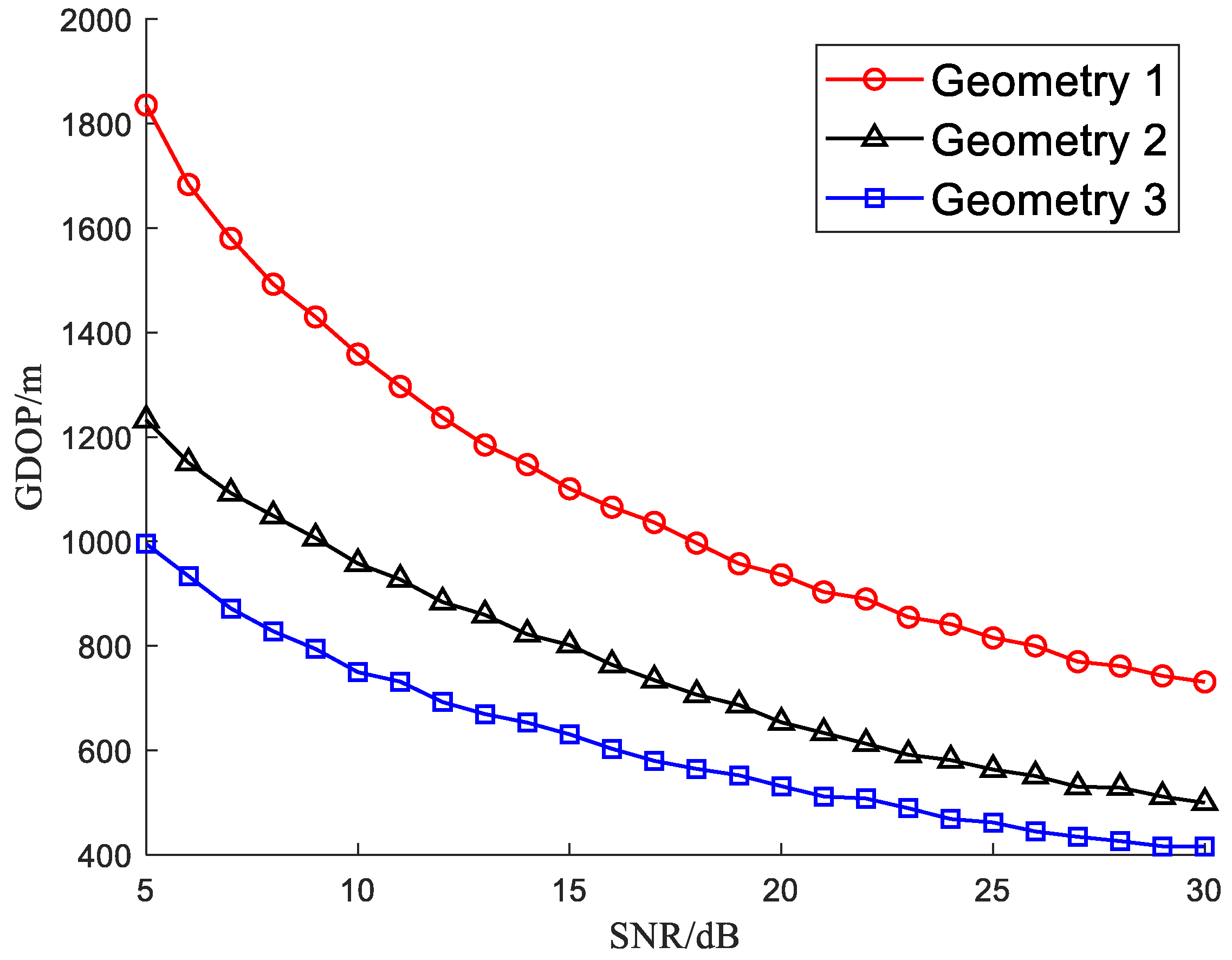
In addition to the number of RISs, the station layout of RISs will also have an impact on the target localization accuracy. In the simulation scene of locating the target at [20, 40, 9] km, three RISs are applied to assist the 2-D radar, and three different station layouts of the RISs are considered. Under different geometry conditions, the GDOP is statistically obtained and compared. The station locations of the RISs are as follows.
Geometry 1: [1.34, 2.68, 0.1] km, [1.34, 2.68, 0.8] km and [1.34, 2.68, 1.5] km;
Geometry 2: [1.34, 2.68, 0.1] km, [1.34, 2.68, 1.3] km and [1.34, 2.68, 2.5] km;
Geometry 3: [1.34, 2.68, 0.1] km, [1.34, 2.68, 1.8] km and [1.34, 2.68, 3.5] km.
In the above three geometry conditions, the baseline of the RISs becomes longer in the pitch dimension.
Figure 6 depicts the simulated GDOP varying with the SNR under three geometry conditions.
By comparing three curves in
Figure 5, it is shown that the GDOP is lower with more assisted RISs. The localization accuracy is improved with the increase of RISs, since more redundant measurements in the auxiliary channels are used for target localization. As shown in
Figure 6, the GDOP in Geometry 3 with the longest baseline is lowest. The localization accuracy of the proposed RIS-assisted 2-D radar becomes higher with the longer baseline of three RISs. The baseline influences the localization accuracy by its effect on the difference in the observation perspective of the target in the pitch dimension. The perspective difference becomes larger with a longer baseline, which will enlarge the observability of the target location and improve the target localization accuracy.
In this study, detailed Monte Carlo simulations are conducted to investigate the effect of the number and the station layout of RISs on the localization accuracy in the RIS-assisted 2-D radar. Simulation results show that increasing the number and the baseline of the assisted RISs can improve the localization accuracy, especially in low SNR conditions. The conclusions are important for optimizing the design of the radar system to improve its localization performance. It is shown that the localization accuracy of the proposed RIS-assisted 2-D radar can be significantly improved by properly configuring the number and location of RISs.
4.4. Target Localization in Multi-Target Scenario
The multi-target localization capability of the proposed RIS-assisted 2-D radar is considered. The 2-D radar located at [0, 0, 0] km is assisted by three RISs to locate four sparse targets in one scanning beam. The locations of the targets are [20, 40, 9] km, [18, 36, 7] km, [24, 48, 12] km and [16, 32, 10] km, and the locations of the RISs are set as [1.34, 2.68, 0.1] km, [1.34, 2.68, 1.3] km and [1.34, 2.68, 2.5] km, respectively.
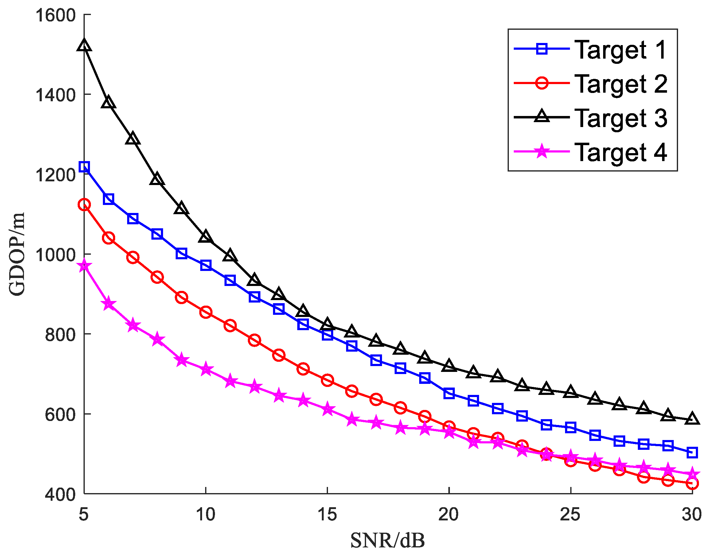
For the first target located at [20, 40, 9] km, its SNR in the direct channel is changing from 5 to 30 dB with a step as 1 dB. Its SNR in the auxiliary channels can be calculated. In addition, it is assumed that the Radar Cross-Sections (RCSs) of the four targets are the same. Then, the SNR of the other targets in the direct channel and the auxiliary channels can be obtained by scaling according to the measured distance information. To obtain reliable simulation results, 5000 Monte Carlo simulation experiments have been carried out, and the simulated GDOP varying with the SNR for each target is given in
Figure 7.
As shown in
Figure 7, the proposed RIS-assisted 2-D radar target position estimation algorithm can obtain acceptable localization accuracy for each target, and the localization accuracy becomes higher with the increasing of the target SNR. For these four targets, target 4 has the highest localization accuracy, which is followed by target 2, target 1 and target 3. This is related to their distances to the 2-D radar, since the distances determine the target SNR. Target 4 is closest to the radar, it has the highest target SNR and the highest localization accuracy, while target 3 is the farthest away from the radar station; it has the lowest SNR and the worst localization accuracy. This is consistent with the analysis of the influence of the SNR on the localization accuracy in
Section 4.1.
4.5. Target Localization with RISs Site Errors
The target localization depends on the accurate location of the RISs. When the site errors of the RISs exist, the target localization accuracy will be reduced to a certain extent. The GDOP with the RISs site errors is simulated in the same single target scenario in
Section 4.2. All the simulation parameters of the targets and the RIS-assisted 2-D radar are the same.
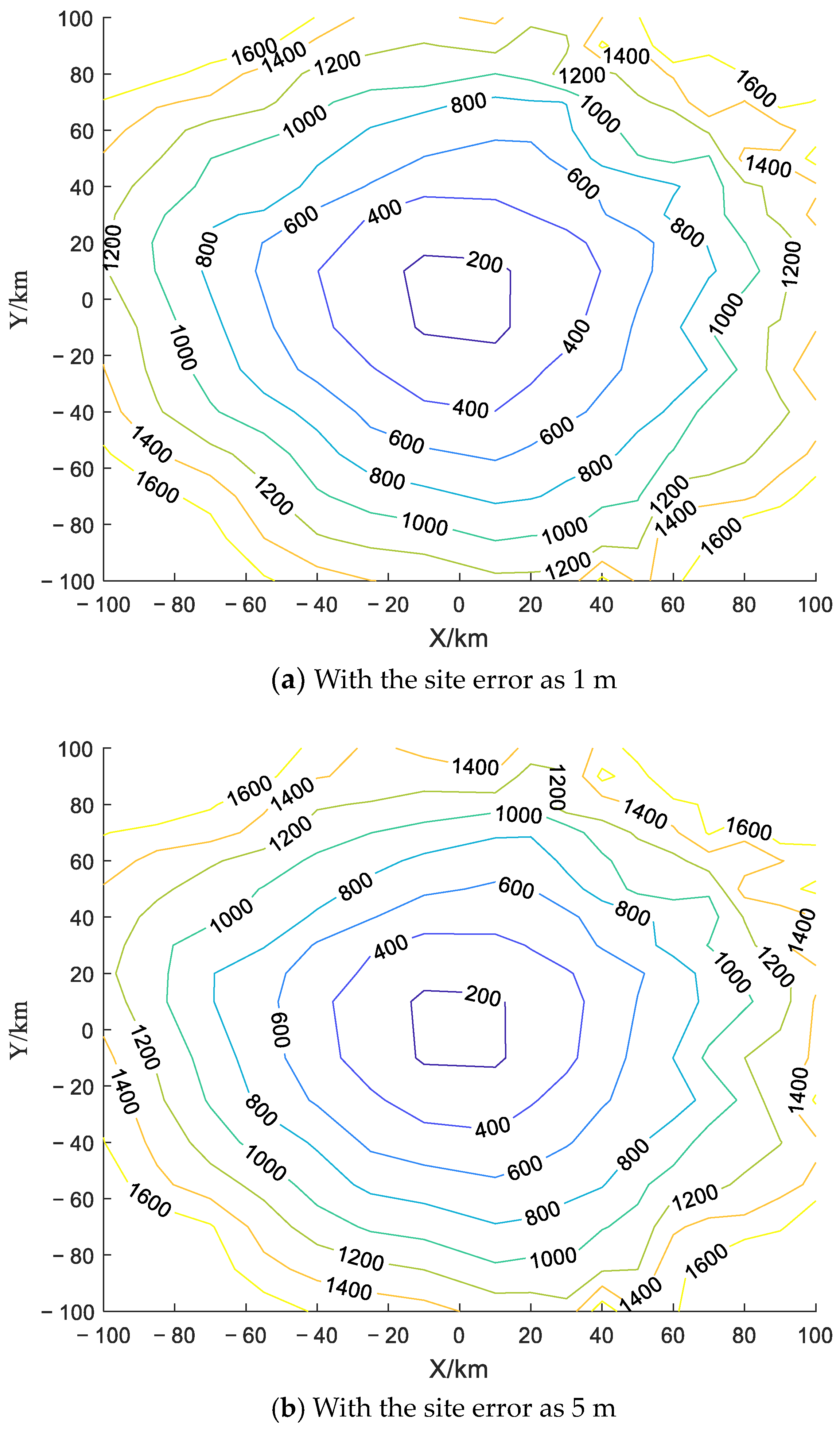
A normally distributed site error is added to the position of the RISs, and it is assumed that the errors of the x-axis, y-axis and z-axis of each RIS meet the independent co-distribution. With the site error as 1 m and 5 m, the simulated GDOP in the detection area of
km is given in
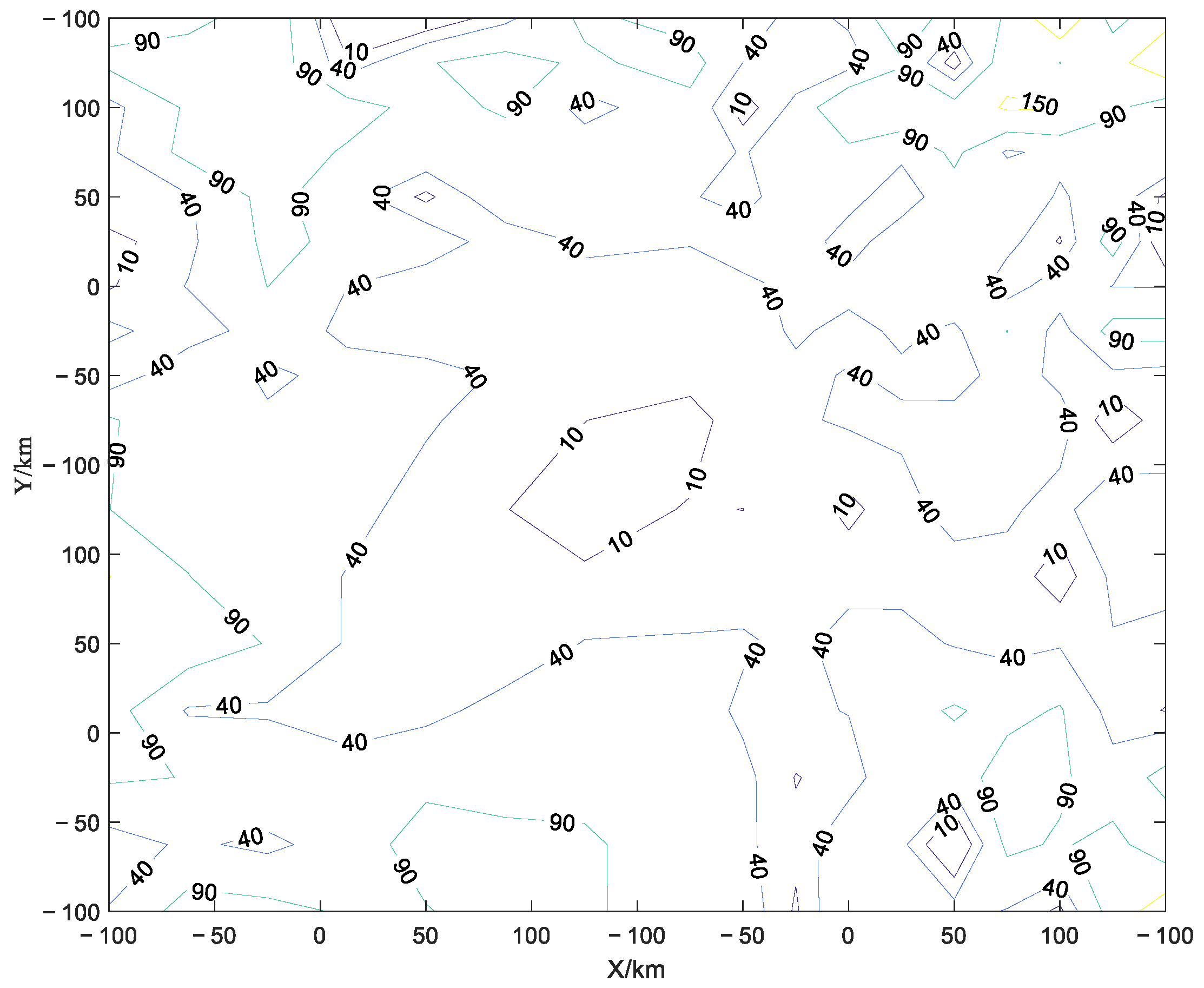
Figure 8. To reflect the effect of the site error, the difference of the GDOP with the site error as 5 m and 1 m is shown in
Figure 9.
Compared with
Figure 4a, the target localization accuracy reduces with the site errors of the RISs. And it is shown in
Figure 9 that the difference between the GDOP is always greater than zero, which indicates that the GDOP becomes higher with the increase in the site error. Therefore, the decline of the localization accuracy becomes more serious with the increase in the site error. This is because the target localization model in the proposed method does not consider the randomness of the site error, leading to the mismatch of the algorithm model.
