Abstract
The real-time tracking of moving objects has extensive applications in various domains. Existing tracking methods typically utilize video image processing, but their performance is limited due to the high information throughput and computational requirements associated with processing continuous images. Additionally, imaging in certain spectral bands can be costly. This paper proposes a non-imaging real-time three-dimensional tracking technique for distant moving targets using single-pixel LiDAR. This novel approach involves compressing scene information from three-dimensional to one-dimensional space using spatial encoding modulation and then obtaining this information through single-pixel detection. A LiDAR system is constructed based on this method, where the peak position of the detected full-path one-dimensional echo signal is used to obtain the target distance, while the peak intensity is used to obtain the azimuth and pitch information of the moving target. The entire process requires minimal data collection and a low computational load, making it feasible for the real-time three-dimensional tracking of single or multiple moving targets. Outdoor experiments confirmed the efficacy of the proposed technology, achieving a distance accuracy of 0.45 m and an azimuth and pitch angle accuracy of approximately 0.03° in localizing and tracking a flying target at a distance of 3 km.
1. Introduction
The real-time tracking of moving objects is widely applicable in various fields such as biomedical science [1,2,3], security surveillance [4,5], and remote sensing [6,7,8]. In the realm of optical detection methods, the use of active detection LiDAR in tracking moving targets has garnered increasing attention from researchers [9,10]. LiDAR measures the target distance, denoted as the ToF (Time-of-Flight), by emitting light pulses and measuring the time taken for the pulse echo to return [11,12]. Through point/line scanning or flash methods, LiDAR systems can obtain information on the complete three-dimensional nature of targets within the field of view, including the azimuth and elevation [13,14,15,16,17,18].
Scanning LiDAR systems that use controlled points or line sources for non-global scene scanning may miss targets in tracking scenarios with moving objects [13,14,15,16]. On the other hand, flash LiDAR, which uses a broad light source to illuminate the entire scene and a Single Avalanche Photodiode (SAPD) array to acquire information, is a detection method suitable for the real-time tracking of moving targets [17,18]. Flash LiDAR that employs a wide-divergence-angle laser illuminates the entire scene at once due to the significant attenuation of echo energy with increasing distance and the dispersal of energy across various pixels in the SAPD array, resulting in a relatively shorter detection range. Additionally, SAPD arrays are costly, and the need to completely detect three-dimensional information for every pixel in the full path results in a high data volume, requiring considerable data transmission, storage, and processing capabilities [17,18]. Table 1 summarizes the advantages and disadvantages of traditional LiDAR detection methods.

Table 1.
Pros and cons of current LiDAR systems in tracking moving targets.
The novel single-pixel imaging LiDAR [8,19] used in this study integrates Time-of-Flight (ToF) methods and single-pixel imaging theory to spatially encode the entire scene, achieving global detection with a single-pixel detector and long-range detection capabilities. This model offers a relatively simple architecture and low data flow, as well as promising prospects for practical applications [20,21,22].
Traditional approaches for tracking moving targets often involve image sequence processing [23,24,25]. However, the speed of single-pixel imaging is relatively slow. Consequently, using image-based positioning is not ideal. Standard Compressed Sensing (CS) formulations and solvers were utilized in [26] to achieve resolutions of up to 256 × 256 pixels within a practical acquisition time of 3 s. The single-pixel three-dimensional imaging system constructed in [27] achieved a 128 × 128 resolution in 3D imaging. In that study, the authors used a comprehensive Hadamard set consisting of 16,384 patterns and their inverses as structured illumination. The illumination time for each pattern was set to 2.66 ms, corresponding to 20 laser pulses. The imaging results were satisfactory, but the entire process of data acquisition and image processing consumed a significant amount of time, approximately 130 s.
The detection frame rate is a crucial metric in real-time tracking applications for moving targets [28,29,30,31,32]. The low imaging efficiency of current single-pixel LiDAR systems makes it challenging to achieve high detection frame rates through continuous image processing. Furthermore, continuous image processing involves extracting effective position feature information from redundant information in the images, necessitating substantial computational and informational throughput.
Given these challenges, we propose obtaining the positional information of targets without relying on images. Single-pixel imaging technology was previously used in some studies to directly extract useful information [33,34,35].
Therefore, researchers have attempted methods that do not require imaging, instead directly utilizing single-pixel detection to obtain target positions. For example, Shi et al. [36] designed a series of modulation patterns using Hadamard matrices to modulate spatial information based on the principle that one-dimensional projection curves contain edge and positional information. This method directly obtained the one-dimensional projection curve of the target scene, achieving a localization frame rate (frequency of position acquisition per second) of approximately 177 Hz using a DMD (digital micromirror device) with a modulation frequency of 22.2 kHz. Zhang et al. [37] utilized six Fourier basis patterns to illuminate a moving target and collected the resulting light signal with a single-pixel detector. This method enabled the direct detection and tracking of the object without image reconstruction using a computationally efficient detection and tracking algorithm. Zha et al. [38] designed a centroid positioning method based on image geometric moment theory using three geometric moment encoding patterns to modulate the target scene. This method directly extracted geometric moments to obtain the target centroid, achieving a localization frame rate of 7.4 kHz using a DMD with the highest modulation frequency of 22.2 kHz.
However, these methods [36,37,38] are limited to two-dimensional spatial localization and have only been validated in laboratory settings. To date, no studies have reported active LiDAR three-dimensional tracking or localization of distant moving targets in complex outdoor scenes.
This study proposes a method for the three-dimensional tracking of distant moving targets and establishes a non-imaging single-pixel detection LiDAR system. The key contribution of this study is its first-time utilization of non-imaging single-pixel LiDAR to achieve the three-dimensional localization of small outdoor targets at long distances. This LiDAR system does not acquire redundant three-dimensional image data of the target but instead extracts feature information relevant to the target’s position to achieve tracking. This method does not rely on traditional imaging techniques for tracking, thereby reducing the data throughput and computational requirements. This system utilizes spatial encoding compression modulation to compress the spatial information of the scene from three dimensions to one and a single-pixel detector to obtain the compressed one-dimensionally encoded information. Our system utilizes a single-pixel detector and differs from flash LiDAR, which instead relies on an SAPD array for image acquisition. However, the data output from a single-pixel detector is relatively small. Additionally, the detection energy is concentrated and does not need to be dispersed across multiple pixels. Compared with flash LiDAR, this method offers certain advantages in detection range. The proposed system also employs a global detection method, which differs from scanning LiDAR in offering a low probability of missed detections when studying moving targets. The second section of this paper introduces the system structure and detection principles of the proposed LiDAR. The third section presents the experimental results and analysis of localizing and tracking a target 3 km away using this LiDAR system. Finally, we conclude this study with a summary and future outlook.
2. Materials and Methods
2.1. Design of Single-Pixel LiDAR
The proposed single-pixel LiDAR system architecture is illustrated in Figure 1a. In this system, a pulsed laser emitting light at a wavelength of 1064 nm illuminates the target scene. A Cassegrain telescope then collects the echoed signals, and a digital micromirror device (DMD) is employed to spatially encode and modulate the echoed signals. The DMD used in the system has a maximum modulation frequency of 22.2 kHz. This DMD is a digitally controllable micro-mirror array with over one million individually controllable units, each capable of orienting the micro-mirror at +12° or −12°. By loading different patterns, the echoed signals from the target scene undergo various encoding modulations. The DMD utilized in the system has a resolution of 1920 × 1080 pixels. The effective modulation area of our modulation pattern occupies a square region measuring 1072 × 1072 pixels, located precisely at the center of the target surface. The modulated signal is split into two paths, with one part reflected by micro mirrors oriented at +12° and the other by micro mirrors oriented at −12°. The single-pixel detector employed in this system is an avalanche photodiode (APD). One of the split reflections is measured via the APD for the echo intensity, while the other is directed to a charge-coupled device (CCD) for monitoring. The analog signal of the APD’s output intensity is converted to a digital signal with a 1 GS/s digitizer and processed in real time with a computer. The complete experimental specifications are detailed in Table 2.

Figure 1.
Structure and optical path diagram of the LiDAR system. (a) The system features three main components: the laser system, a Schmidt–Cassegrain telescope, and a dual-channel optical reception system. (b) Schematic diagram of the system’s optical path. The light emitted by the laser system illuminates the object under measurement, and the returned light, collected by the telescope, is projected onto the DMD. After modulation with the DMD, one path is directed to the APD to obtain the total intensity, while the other path is received and imaged using the CCD.

Table 2.
LiDAR system specifications.
2.2. Non-Imaging Three-Dimensional Localization Method for Moving Targets
2.2.1. Model for Detection and Tracking of Moving Targets in Single-Pixel Lidar
First, we assume that the three-dimensional scene containing the target is represented as f(x,y,z), where the target is in motion at a specific time t. This relationship can be expressed as follows:
where x, y, z are spatial coordinates; x0, y0, z0 are the initial spatial coordinates of the target; and , , represent the target’s velocities in three directions.
A single-pixel LiDAR system, as depicted in Figure 1, is utilized for target detection. Here, we assume that the pulse waveform of the emitted laser is . Considering the linear relationship between the depth information z and the signal’s return time , , the functional expression for the target scene can be equivalently written as . At time t, the encoded pattern loaded onto the spatial light modulator is denoted as Sn, and the one-dimensional echo signal obtained with the APD detector can be expressed as follows [39,40]:
This is a laser intensity transmission function, where represents the optical transmission efficiency of the emission system, is the optical reception system efficiency, and is the laser pulse transmittance in the atmosphere ( in the equation arises from the laser signal’s dual traversal of the atmospheric environment: once during its emission and another during its return after reflection). In addition, c is the speed of light, * denotes the convolution operation (the return intensity of the laser irradiating the target space can be obtained through convolution of the emission signal with the reflectivity function of the target space), D is the x, y cross-section of the detection field, is the modulation matrix loaded by the DMD, and includes background light noise and detector noise. During detection, a differential measurement technique is employed to eliminate noise [41]. Specifically, we apply Hadamard modulation patterns, where each modulation pattern is applied twice (positive and negative) on the DMD to obtain the corresponding intensities In+ and In−. Then, subtracting those values yields the corresponding reflectance intensity. The background noise is subtracted after two measurements, effectively reducing its impact on the results.
2.2.2. Model for Detecting and Tracking Moving Targets in Single-Pixel Lidar
Next, a series of modulation patterns are employed to modulate the target scene, and a series of detection intensities are obtained using a single-pixel detector. In this section, we introduce the composition of the relevant modulation patterns and explain how to extract the three-dimensional information of the target from the reflected signal.
In Formula (2), Sn(x,y) represents the modulation matrix loaded by the spatial light modulator. The single-pixel non-imaging detection method proposed in [36] utilizes specific modulation patterns to directly obtain the one-dimensional projection curves of a scene. Figure 2a illustrates the projection curves for a two-dimensional slice of the 3D scene. As shown in Figure 2b, the modulation patterns used to directly obtain the projection curve are generated via a Hadamard matrix. This generation process involves using each row and column of the Hadamard matrix to construct a modulation pattern. For instance, the first row of the Hadamard matrix Sx,1 is used to construct the modulation pattern S′x,1(x,y), and the first column S1,y is used to construct the modulation pattern S′y,1(x,y). Specifically, each row of S′x,1(x,y) is equal to Sx,1, and each column of S′y,1(x,y) is equal to S1,y.
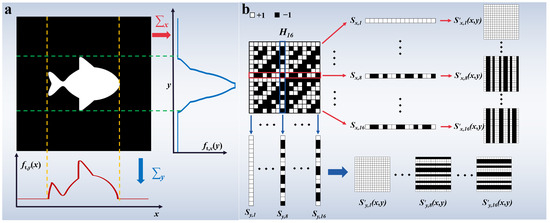
Figure 2.
The principle of projection curve measurement. (a) The projection curves of a slice image of the 3D scene. (b) The generation process of modulation patterns, where each row and column of the Hadamard matrix is utilized to construct a modulation pattern. For example, the first row of the Hadamard matrix Sx,1 is used to construct the modulation pattern S′x,1(x,y), and the first column S1,y is used to construct the modulation pattern S′y,1(x,y). The specific construction method involves setting each row of S′x,1(x,y) equal to Sx,1 and each column of S′y,1(x,y) equal to S1,y.
The echo signals of the target scene can be modulated using the aforementioned modulation patterns, S′x,n(x,y) and S′y,n(x,y). The modulation duration is t, ensuring coverage of the entire path of the echo signal. The echo signals obtained from the target scene are denoted as In,x, In,y. Since the depth z of each slice image in a 3D scene is linearly related to the echo time , the projection curve of the slice images at various depths can be written as , . The corresponding equation is as follows:
Figure 3 provides an overview of the process for calculating the scene’s projection curves. When detecting and tracking moving targets within the scene, a laser pulse is emitted towards the target scene, and the reflected echo signal is detected using an APD. A high-speed digitizer is then used to digitally sample the analog signal from the APD, and the position of the peak value in the echo signal is detected. The real-time distance information of the moving target is obtained based on the position of the peak value in the echo signal, and the azimuth and pitch information of the target is calculated using Formula (3) based on the intensity of the peak value. The azimuth angle refers to the angle between the line from the observation point to the observed target and the forward direction from the observation point. The pitch angle refers to the angle between the line from the observation point to the observed target and the horizontal plane. Ultimately, this method achieves the real-time three-dimensional positioning of moving targets.
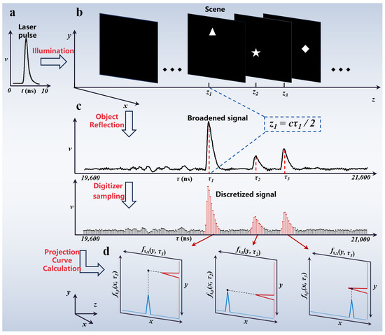
Figure 3.
Overview of the detection and processing process; (a) time waveform of the system-emitted pulse laser; (b) drones distributed at different distances in the scene; (c) echo signal received by the detector, with discrete sampling of the signal. The distance information of the target can be calculated based on the time corresponding to the peak value, and the azimuth and pitch information of the target can be calculated based on the peak value; (d) projection curves of the target scene calculated using the intensity of the peak signal. The maximum point of the projection curve corresponds to the position of the target in the field of view.
To detect and track distant targets in three dimensions when the targets typically occupy a relatively small portion of the field of view, the maximum point of the projection curve can be directly used as the target position. The three-dimensional positional information, xm, ym, zm, of the target is given as follows:
where x, y, z are spatial coordinates; and m represents the index of targets when there are multiple targets at different depths within the field of view. The term fmax is defined as a function that seeks the maximum point on a curve. In the above equation, fmax is used to locate the coordinates with the maximum value of the projection curve, thereby determining the position of the target in the field of view. When describing the three-dimensional positions of distant objects, it is common to use the azimuth angle, elevation angle, and distance relative to the observation point. These three parameters correspond, respectively, to the x, y, and z axes of the three-dimensional coordinate system.
3. Results
This section presents the experimental results of the proposed single-pixel LiDAR system for the three-dimensional tracking of small moving drones at a distance of 3 km. A schematic diagram of the experimental system is illustrated in Figure 4a. To assess the multi-target positioning capabilities of the LiDAR system, three DJI Phantom 4 drones were simultaneously flown. As shown in Figure 4b, the drones had a wheelbase of 0.35 m and height of 0.3 m. The drones flew within the field of view, and the LiDAR system was used for the three-dimensional measurements, as depicted in Figure 4a, where SYS represents our LiDAR system. The APD output signal is connected to a DAS (data acquisition system), which converts the analog signal into a digital signal. The data are then transmitted to a computer, where real-time processing of the data is performed using algorithms to obtain the three-dimensional information of the targets, including the distance, azimuth, and pitch angle. Next, the image signal from the CCD camera is directly connected to the computer for display. The laser operates with a repetition frequency of 400 Hz, and the DMD modulation frequency is synchronized with the laser. As described in the Materials and Methods, 16 modulation patterns were used to obtain the horizontal projection curve, and 16 modulation patterns were used to obtain the vertical projection curve. Each pattern was modulated twice—positively and negatively. Therefore, this system obtains the target’s position after every 64 modulations and measurements.
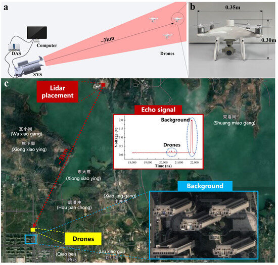
Figure 4.
Schematic diagram of the experimental system. (a) The design of the experimental system, where the LiDAR system detects drones in the field of view. The APD output analog signal is discretely collected by the DAS and transmitted to the computer for processing. The image captured by the CCD camera is then transmitted in real time to the computer for display. (b) The drones used in the experiment, with a drone height of 0.3 m and width of 0.35 m. (c) The placement of the LiDAR system and the area of the drones’ flight, with a building complex behind the drones, represented in the LiDAR detection signal as a larger echo intensity.
The quantity of objects in the scene is determined by the number of peaks in the return signal, as depicted in Figure 4c (Echo signal). In this scenario, four objects were present: three with relatively weaker return signals and one building exhibiting a very strong return signal. Notably, the return signal from the building presented distinctive features, with the signal intensity reaching the saturation level of the detector.
Algorithm 1 presents pseudo code for the signal processing and three-dimensional target position calculation process. Data processing entails three main parts. The first part calculates the distance using the Time-of-Flight (ToF) method, where the echo signals are accumulated within one modulation period, and the peak position is searched within the accumulated signal, where c1 and c2 are, respectively, the left and right widths of the peak integration region. The function find_peakposition(data) then returns a vector with the local maxima (peaks) of the input data. A local peak is a data sample larger than its two neighboring samples. The vector contains the positions of all peaks, with its length corresponding to the quantity of peaks identified. This number of peaks directly correlates with the quantity of objects present in the scene. The second part calculates the projection curve based on Equations (3) and (4) and integrates the intensity around the peak region to obtain Ix,n(τm) and Iy,n(τm). Here, the left and right widths of the region are denoted as c1 and c2. Next, we substitute Ix,n(τm) and Iy,n(τm) into Equations (3) and (4) to calculate the projection curve. The third part extracts three-dimensional information based on Equations (5) and (6).
| Algorithm 1: Pseudo code for processing and three-dimensional target positioning. |
| Top ranging: τm = find_peakposition(Sum_Im) return τm Projection curve: Ix,n(τm)←sum(Ix,n(τm−c1:τm+c2)) Iy,n(τm)←sum(Iy,n(τm−c1:τm+c2)) *1 return ft,x(y,τm), ft,y(x,τm) 3D positioning: zm = ctm/2 (xm, ym) = fmax[ft,x(y,zm), ft,y(x,zm)] return xm, ym, zm |
The system conducts peak detection for each echo signal corresponding to a modulation pattern during operation of the system. Assuming n peaks are found, the system directly computes the target distance using Equation (6) based on the peak positions. Around each identified peak, a neighborhood of hundreds of values is summed and temporarily stored. The system executes 32 iterations of modulation and echo signal processing, totaling 0.08 s. After acquiring n × 32 summed values, Equations (3) and (4) are applied to derive the projection curve of the target scene at each peak position. By locating the maximum value position on the projection curve, the system obtains target positional information. Notably, our system operates on an i7 3770 CPU without a GPU configuration. Thus, data computations must be performed in real time on the CPU, indicating that our system can achieve real-time target tracking under a minimal computational load. The experimental results and materials, including raw data and code, are provided in the Supplementary Materials.
3.1. Distance Accuracy
To assess the ranging capabilities of the LiDAR system, we flew a DJI Phantom 4 RTK drone. The drone is manufactured by DJI, based in Shenzhen, China. The drone began its flight at the LiDAR system’s position and, after flying to approximately 3000 m from the takeoff point, continued its flight, which involved changes in distance. The LiDAR system was used to measure the drone’s flight, and the ensuing measurement data were compared with those from the actual drone flight recorded using the DJI Phantom 4. The recorded distance values from the Phantom 4 are considered here as the ground truth. A comparison between the LiDAR system’s measured distance values (represented by the blue dashed line) and the recorded drone distances (represented by the red dashed line) is shown in Figure 5. Here, the x-axis represents time. Table 3 compares the distances recorded by the drone and those measured using the LiDAR system. The drone flight data were recorded every 100 ms, and the LiDAR system requires 160 ms for one distance detection. Thus, Table 3 presents a comparison of values at the moments of coincidence, representing the values recorded in the flight records and the values obtained from the LiDAR system. The system’s average distance positioning absolute error was 0.45 m. This error may be attributable to temporal errors caused by jitter in the laser emitter’s emission time or measurement delays.
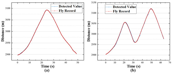
Figure 5.
Distance detection results; (a,b) two flight trajectories, with the x-axis representing time and the y-axis representing distance. The blue dashed line represents the system’s measured distance values, while the red dashed line represents the recorded drone distances.

Table 3.
The distance measurement results of LiDAR system for a distant target.
3.2. Angular Positioning Accuracy
To test the angular positioning accuracy of the LiDAR system, we launched a DJI Phantom 4 RTK drone. The drone was launched from the LiDAR position and flew to a distance of 3 km from the LiDAR. The drone’s flight involved changes in altitude, which were measured with the LiDAR system. The measurement data were saved, and the flight record was obtained from the drone’s controller. The drone’s angular position in the LiDAR system was calculated using the drone’s flight record, including the distance d and height h from the takeoff point. We calculated the pitch angle of the drone relative to the LiDAR system using the following formula:
where h is the drone’s height from the takeoff point, d is the distance between the LiDAR system and the drone, and is the fixed pitch angle of the LiDAR system.
A comparison between the LiDAR system’s measured data and the actual drone data is shown in Figure 6. Figure 6a,b illustrate two flight trajectories, where the x-axis represents time, and the y-axis represents the drone’s pitch angle relative to the LiDAR system. The black dashed line represents the true pitch angle obtained based on the drone’s flight record, while the red dashed line represents the drone’s position measured with the LiDAR system.
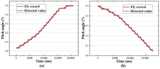
Figure 6.
Single-target positioning measurement results; (a,b) two flight trajectories, with the x-axis representing time and the y-axis representing the pitch position of the drone in the field of view. The black dashed line represents the true pitch position obtained from the drone’s flight record, while the red dashed line represents the pitch position measured with the LiDAR system.
Figure 6 shows that the LiDAR system accurately measured the pitch position of the drone in the field of view. The stepped appearance in the measurement values is attributed to the system’s measurement precision. The system’s field of view angle is 0.5° × 0.5°, and the spatial modulation pattern resolution is 16 × 16, resulting in an angular positioning resolution of approximately 0.03°.
Table 4 presents a segment of angle detection data aimed at a distant target, corresponding to Figure 6a. The accuracy of the system’s angular positioning depends on the resolution of the modulation matrix. Increasing the angular positioning accuracy requires more modulations, which, in turn, decreases the system’s positioning frequency. For example, using a spatial modulation pattern with a resolution of 32 × 32, the system’s angular resolution would be precise to 1/32 of the field of view. However, the positioning frequency would be halved compared to the current frequency.

Table 4.
The angular measurement results of LiDAR system for the distant target.
3.3. Single-Target 3D Tracking
To assess the system’s three-dimensional tracking and positioning capabilities, the system was used to detect and track the target, a DJI Phantom 4 RTK drone under nighttime conditions, with the environment shown in Figure 4c. The drone was positioned approximately 3 km away from the test point, with buildings located in the back of the flight area. Figure 7a presents the 3D target position obtained with the LiDAR system at a particular moment, calculated based on the echo signal and projection curve. The horizontal position of the target within the field of view is represented on the x-axis using the azimuth angle, and the vertical position is represented on the y-axis using the pitch angle. The distance to the target was 2998.7 m. Figure 7b shows the scene image obtained using the CCD camera, with red dots representing the light emitted by the drone and blue circles composed of dashed lines identifying the lights from the buildings located in the back. In the Supplementary Materials, Video S1 demonstrates the real-time tracking process. Here, we present four windows: the accumulated signal, 3D presentation, 2D presentation, and image captured by the CCD. In the fourth window, the image obtained using the CCD demonstrates that the background light on the buildings remained fixed as the drone moved within the field of view. Figure 7c illustrates the planned trajectory of the drone’s movement, and Figure 7d three-dimensionally depicts the continuous motion trajectory of the drone obtained using the LiDAR system.
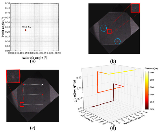
Figure 7.
Three-dimensional tracking results of a single target at 3 km: (a) the target position obtained at a certain moment during the measurement process; (b) image from the CCD at that moment; (c) the approximate flight trajectory of the drone moving in the horizontal, vertical, and longitudinal directions; (d) the continuous three-dimensional drone flight trajectory obtained with the LiDAR system. To make the distance changes more distinguishable with a three-dimensional trajectory, the color of the trajectory lines changes gradually with distance.
Figure 7a clearly shows the object’s position in the field of view, with an azimuth angle of approximately 0.16°, a pitch angle of about 0.22°, and a target distance of 2998.7 m. Figure 7b shows the image obtained with the CCD camera at the same moment, in which the bright spot within the red box represents the drone, whose position corresponded well with that in Figure 7a. Comparing Figure 7c with Figure 7d shows that the drone followed the path and that the LiDAR detected the drone’s trajectory consistent with that path.
3.4. Multi-Target 3D Tracking
To assess the system’s capabilities in multi-target three-dimensional tracking, we conducted simultaneous tests with three drones in the same environment, as described in Section 3.3. The results obtained with the LiDAR system are illustrated in Figure 8. Figure 8a1 shows the three-dimensional information of the targets calculated with the LiDAR system using the echo signals. The x-axis represents the azimuth angle of the targets in the field of view, and the y-axis represents the pitch angle. The distances of the targets are marked on the graph as 2990.90 m, 3027.95 m, and 3050.35 m. The color bar, which transitions from red to black, corresponds to the distances from near to far. Figure 8b1 shows the image obtained with the CCD camera, with the red dots indicating lights emitted by the drones. Comparing Figure 8a1 with Figure 8b1 shows that the three target positions obtained using the LiDAR system corresponded one-to-one with the images obtained via the CCD camera. Figure 8a1–f1,a2–f2 sequentially present multiple detection frames during the tracking process with the LiDAR system. The three-dimensional information of the targets is provided in Figure 8a1–f1, while the images obtained with the CCD camera are presented in Figure 8a2–f2. In Figure 8a2–f2, yellow spots represent lights emitted from buildings behind the flying area. These lights are attributed to the relatively low altitude of the drones, which ranged from 30 to 80 m, and the nighttime testing conditions.
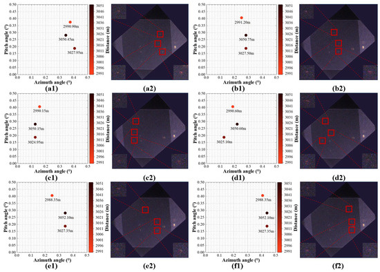
Figure 8.
Results of LiDAR multi-target tracking. (a1–f1) Sequential display of multiple detection frames during the tracking process, showing the three-dimensional information of the drones obtained with the LiDAR system. The x-axis represents the horizontal position of the targets in the field of view using the azimuth angle in degrees, and the y-axis represents the vertical position using the pitch angle in degrees. Distances are marked on the graph, assisted by a color bar. (a2–f2) Sequential display of multiple detection frames during the tracking process, showing the images obtained via the CCD camera, with drone positions highlighted using red boxes.
Figure 9a–d illustrate the three-dimensional motion trajectories of four groups of targets with different trajectories within the field of view, as detected by the LiDAR system. In these segments, multiple targets within the field of view are distributed at different distances. These targets primarily exhibit motion in the azimuth and elevation within their respective distance slices. The three axes represent the horizontal position, pitch position, and distance of the targets. The azimuth angle is used for horizontal position and pitch angle for the pitch position, with the distance measured in meters. The LiDAR system successfully captured the three-dimensional trajectories of the targets at different distances. The distances for each moving object are annotated in Figure 9. For example, object 1 was located at 3259 m, object 2 was located at 3507 m, and object 3 was located at 3656 m (Figure 9a).
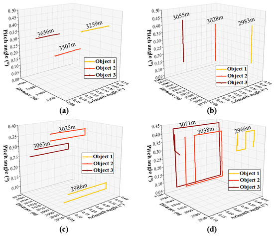
Figure 9.
Results of LiDAR system’s multi-target three-dimensional detection. (a–d) The three-dimensional motion trajectories of multiple targets within the field of view. The three axes represent the horizontal position, pitch position, and distance of the targets. The azimuth angle is used for the horizontal position and pitch angle for the pitch position; the distance is in meters.
In the Supplementary Materials, Video S2 demonstrates the LiDAR system’s three-dimensional tracking of the targets. Here, we present four windows: the accumulated signal, 3D presentation, 2D presentation, and image captured by the CCD. The accumulated signal in the first windows shows all the echo signals accumulated during a single localization period, while the 3D presentation displays the three-dimensional tracking trajectory of the target. Next, the 2D presentation primarily shows the target’s movement in the horizontal and vertical directions, providing an intuitive comparison with the fourth window, the image captured by the CCD.
4. Discussion
In this research, we developed a real-time three-dimensional tracking system for moving objects using a single-pixel LiDAR and a corresponding localization and tracking method. This system demonstrated the ability to engage in the real-time three-dimensional tracking of moving targets. Through experiments, we validated the effectiveness of the LiDAR system in detecting moving targets at a distance of three kilometers in real-world scenarios, with a target distance positioning error of 0.45 m and angular positioning accuracy exceeding 0.03 degrees.
In terms of technology, this method differs from that of traditional LiDAR systems. Unlike point scanning/line scanning LiDAR systems, this single-pixel LiDAR system employs a global detection approach, which avoids the issue of missed detections during the tracking of moving objects. Compared to flash LiDAR, our single-pixel LiDAR system utilizes a single-pixel detector. The data output from a single-pixel detector are relatively small. Additionally, the detection energy is concentrated and does not require dispersal across multiple pixels. Our proposed LiDAR system has unique application value in real-time detection and tracking at long distances.
Currently, our LiDAR system is limited by the output frequency of the laser, resulting in lower positioning resolution and frame rates. Increasing the laser output frequency will enhance the LiDAR system’s detection frame rate. For instance, when the laser output frequency is increased to match the modulation rate of the spatial light modulator at 22.2 kHz, under a 16 × 16 angular resolution, the maximum positioning frame rate can reach approximately 347 Hz. With an angular resolution of 64 × 64, the angular positioning accuracy is higher than 0.008 degrees, and the positioning frame rate can reach 86 Hz. Increasing the resolution of the spatial coding modulation pattern to achieve higher angular resolution comes at the cost of a reduced detection frame rate. Dynamic adjustments to positioning frame rates and resolutions can be made based on the requirements of different usage scenarios.
5. Conclusions
In this paper, we presented the principles of our non-imaging single-pixel LiDAR system and experimentally validated its ability to three-dimensionally localize small targets at long distances. The key contribution of our research is the first-time utilization of non-imaging single-pixel LiDAR to achieve the three-dimensional localization of small outdoor targets at long distances.
However, there are several aspects of this system that could be improved in future work. For instance, the current system operates with a laser repetition frequency of 400 Hz. Utilizing a laser with a higher repetition frequency could result in faster localization. Additionally, redesigning the optical path to incorporate two digital micromirror devices (DMDs) at the receiver end for modulation in different directions could enable the simultaneous acquisition of projection curves in both the horizontal and vertical directions, thereby significantly enhancing the localization speed. Addressing the issue of low angular localization accuracy could involve using modulation patterns with higher resolution to more precisely determine the target’s position within the field of view.
In our future work, further explorations could focus on this system’s resilience to disturbances and its ability to distinguish between different objects. For instance, incorporating pattern recognition methods to integrate signal characteristics with continuously obtained positional data could facilitate the classification and assessment of targets within the field of view. This approach could significantly enhance the practicality of this system.
Supplementary Materials
The following supporting information can be downloaded at: https://zenodo.org/doi/10.5281/zenodo.10723036 (accessed on 28 February 2024).
Author Contributions
Conceptualization, Z.G., D.S. and Y.W.; data curation, Z.G. and D.S.; formal analysis, Z.G., D.S. and Z.H.; investigation, Z.G., D.S., Z.H., R.J., Z.L. and H.C.; methodology, Z.G. and D.S.; project administration, Z.G. and D.S.; resources, Z.G. and D.S.; software, Z.G. and D.S.; supervision, Z.G., D.S. and Y.W.; validation, Z.G., D.S., Z.H., R.J., Z.L. and H.C.; visualization, Z.G. and D.S.; writing—original draft, Z.G. and D.S.; writing—review and editing, Z.G. and D.S. All authors have read and agreed to the published version of the manuscript.
Funding
The Youth Innovation Promotion Association of the Chinese Academy of Sciences, Chinese Academy of Sciences (No. 2020438); the Open Project of Advanced Laser Technology Laboratory of Anhui Province, Anhui Provincial Department of Science and Technology (No. AHL2021KF03); the Anhui International Joint Research Center for Ancient Architecture Intellisencing and Multi-Dimensional Modeling, Anhui Provincial Department of Science and Technology (No. GJZZX2022KF02); the HFIPS Director’s Fund, Hefei Institutes of Physical Science (grant No. YZJJ202404-CX and YZJJ202303-TS); and the Anhui Provincial Key Research and Development Project, Anhui Provincial Department of Science and Technology (No. 202304a05020053).
Data Availability Statement
The raw data collected during the experiment and all process code can be accessed from https://zenodo.org/doi/10.5281/zenodo.10723036 (accessed on 28 February 2024).
Conflicts of Interest
The authors declare no conflicts of interest.
References
- Greenberg, J.; Krishnamurthy, K.; Brady, D. Compressive single-pixel snapshot X-ray diffraction imaging. Opt. Lett. 2014, 39, 111–114. [Google Scholar] [CrossRef] [PubMed]
- Lochocki, B.; Gambín, A.; Manzanera, S.; Irles, E.; Tajahuerce, E.; Lancis, J.; Artal, P. Single pixel camera ophthalmoscope. Optica 2016, 3, 1056–1059. [Google Scholar] [CrossRef]
- Dutta, R.; Manzanera, S.; Gambín-Regadera, A.; Irles, E.; Tajahuerce, E.; Lancis, J.; Artal, P. Single-pixel imaging of the retina through scattering media. Biomed. Opt. Express 2019, 10, 4159–4167. [Google Scholar] [CrossRef] [PubMed]
- Gibson, G.M.; Sun, B.; Edgar, M.P.; Phillips, D.B.; Hempler, N.; Maker, G.T.; Malcolm, G.P.; Padgett, M.J. Real-time imaging of methane gas leaks using a single-pixel camera. Opt. Express 2017, 25, 2998–3005. [Google Scholar] [CrossRef] [PubMed]
- Nutt, K.J.; Hempler, N.; Maker, G.T.; Malcolm, G.P.; Padgett, M.J.; Gibson, G.M. Developing a portable gas imaging camera using highly tunable active-illumination and computer vision. Opt. Express 2020, 28, 18566–18576. [Google Scholar] [CrossRef] [PubMed]
- Ma, J. Single-pixel remote sensing. IEEE Geosci. Remote Sens. Lett. 2009, 6, 199–203. [Google Scholar]
- Yu, W.-K.; Liu, X.-F.; Yao, X.-R.; Wang, C.; Zhai, Y.; Zhai, G.-J. Complementary compressive imaging for the telescopic system. Sci. Rep. 2014, 4, 5834. [Google Scholar] [CrossRef]
- Gong, W.; Zhao, C.; Yu, H.; Chen, M.; Xu, W.; Han, S. Three-dimensional ghost imaging lidar via sparsity constraint. Sci. Rep. 2016, 6, 26133. [Google Scholar] [CrossRef]
- Sun, Y.; Wang, C.; Wang, Z.; Liao, J. Efficient algorithm for tracking the single target applied to optical-phased-array LiDAR. Appl. Opt. 2021, 60, 10843–10848. [Google Scholar] [CrossRef]
- Li, Z.; Liu, B.; Wang, H.; Yi, H.; Chen, Z. Advancement on target ranging and tracking by single-point photon counting lidar. Opt. Express 2022, 30, 29907–29922. [Google Scholar] [CrossRef]
- Dickey, J.O.; Bender, P.L.; Faller, J.E.; Newhall, X.X.; Ricklefs, R.L.; Ries, J.G.; Shelus, P.J.; Veillet, C.; Whipple, A.L.; Wiant, J.R.; et al. Lunar Laser Ranging: A Continuing Legacy of the Apollo Program. Science 1994, 265, 482–490. [Google Scholar] [CrossRef] [PubMed]
- Lee, J.; Kim, Y.-J.; Lee, K.; Lee, S.; Kim, S.-W. Time-of-flight measurement with femtosecond light pulses. Nat. Photonics 2010, 4, 716–720. [Google Scholar] [CrossRef]
- Yoneda, K.; Tehrani, H.; Ogawa, T.; Hukuyama, N.; Mita, S. Lidar scan feature for localization with highly precise 3-D map. In Proceedings of the 2014 IEEE Intelligent Vehicles Symposium Proceedings, Dearborn, MI, USA, 8–11 June 2014; pp. 1345–1350. [Google Scholar]
- Zeng, S. A tracking system of multiple LiDAR sensors using scan point matching. IEEE Trans. Veh. Technol. 2013, 62, 2413–2420. [Google Scholar] [CrossRef]
- Gu, S.; Zhang, Y.; Yang, J.; Kong, H. Lidar-based urban road detection by histograms of normalized inverse depths and line scanning. In Proceedings of the 2017 European Conference on Mobile Robots (ECMR), Paris, France, 6–8 September 2017; pp. 1–6. [Google Scholar]
- Hu, X.; Ye, L. A fast and simple method of building detection from LiDAR data based on scan line analysis. ISPRS Ann. Photogramm. Remote Sens. Spat. Inf. Sci. 2013, 2, 7–13. [Google Scholar] [CrossRef]
- Tian, Z.; Yang, G.; Zhang, Y.; Cui, Z.; Bi, Z. A range-gated imaging flash Lidar based on the adjacent frame difference method. Opt. Lasers Eng. 2021, 141, 106558. [Google Scholar] [CrossRef]
- Zhou, G.; Yang, J.; Li, X.; Yang, X. Advances of flash LiDAR development onboard UAV. Int. Arch. Photogramm. Remote Sens. Spat. Inf. Sci. 2012, 39, 193–198. [Google Scholar] [CrossRef]
- Radwell, N.; Johnson, S.D.; Edgar, M.P.; Higham, C.F.; Murray-Smith, R.; Padgett, M.J. Deep learning optimized single-pixel LiDAR. Appl. Phys. Lett. 2019, 115, 231101. [Google Scholar] [CrossRef]
- Zang, Z.; Li, Z.; Luo, Y.; Han, Y.; Li, H.; Liu, X.; Fu, H. Ultrafast parallel single-pixel LiDAR with all-optical spectro-temporal encoding. APL Photonics 2022, 7, 046102. [Google Scholar] [CrossRef]
- Wang, Z.; Zhao, W.; Zhai, A.; He, P.; Wang, D. DQN based single-pixel imaging. Opt. Express 2021, 29, 15463–15477. [Google Scholar] [CrossRef]
- Sun, S.; Zhao, W.; Zhai, A.; Wang, D. DCT single-pixel detecting for wavefront measurement. Opt. Laser Technol. 2023, 163, 109326. [Google Scholar] [CrossRef]
- Hosseinpoor, H.; Samadzadegan, F.; DadrasJavan, F. Pricise target geolocation and tracking based on UAV video imagery. Int. Arch. Photogramm. Remote Sens. Spat. Inf. Sci. 2016, 41, 243–249. [Google Scholar] [CrossRef]
- Yang, X.; Shi, J.; Zhou, Y.; Wang, C.; Hu, Y.; Zhang, X.; Wei, S. Ground moving target tracking and refocusing using shadow in video-SAR. Remote Sens. 2020, 12, 3083. [Google Scholar] [CrossRef]
- Benfold, B.; Reid, I. Stable multi-target tracking in real-time surveillance video. In Proceedings of the CVPR 2011, Colorado Springs, CO, USA, 20–25 June 2011; pp. 3457–3464. [Google Scholar]
- Howland, G.A.; Lum, D.J.; Ware, M.R.; Howell, J.C. Photon counting compressive depth mapping. Opt. Express 2013, 21, 23822–23837. [Google Scholar] [CrossRef] [PubMed]
- Sun, M.-J.; Edgar, M.P.; Gibson, G.M.; Sun, B.; Radwell, N.; Lamb, R.; Padgett, M.J. Single-pixel three-dimensional imaging with time-based depth resolution. Nat. Commun. 2016, 7, 12010. [Google Scholar] [CrossRef]
- Sun, S.; Hu, H.-K.; Xu, Y.-K.; Li, Y.-G.; Lin, H.-Z.; Liu, W.-T. Simultaneously tracking and imaging a moving object under photon crisis. Phys. Rev. Appl. 2022, 17, 024050. [Google Scholar] [CrossRef]
- Sun, S.; Gu, J.-H.; Lin, H.-Z.; Jiang, L.; Liu, W.-T. Gradual ghost imaging of moving objects by tracking based on cross correlation. Opt. Lett. 2019, 44, 5594–5597. [Google Scholar] [CrossRef] [PubMed]
- Hu, H.-K.; Sun, S.; Lin, H.-Z.; Jiang, L.; Liu, W.-T. Denoising ghost imaging under a small sampling rate via deep learning for tracking and imaging moving objects. Opt. Express 2020, 28, 37284–37293. [Google Scholar] [CrossRef]
- Jiang, W.; Yin, Y.; Jiao, J.; Zhao, X.; Sun, B. 2,000,000 fps 2D and 3D imaging of periodic or reproducible scenes with single-pixel detectors. Photonics Res. 2022, 10, 2157–2164. [Google Scholar] [CrossRef]
- Ma, M.; Wang, C.; Jia, Y.; Guan, Q.; Liang, W.; Chen, C.; Zhong, X.; Deng, H. Rotationally synchronized single-pixel imaging for a fast-rotating object. Appl. Phys. Lett. 2023, 123, 081108. [Google Scholar] [CrossRef]
- Yan, R.; Li, D.; Zhan, X.; Chang, X.; Yan, J.; Guo, P.; Bian, L. Sparse single-pixel imaging via optimization in nonuniform sampling sparsity. Opt. Lett. 2023, 48, 6255–6258. [Google Scholar] [CrossRef]
- Cui, H.; Cao, J.; Hao, Q.; Zhou, D.; Zhang, H.; Lin, L.; Zhang, Y. Improving the quality of panoramic ghost imaging via rotation and scaling invariances. Opt. Laser Technol. 2023, 160, 109102. [Google Scholar] [CrossRef]
- Ma, M.; Liang, W.; Zhong, X.; Deng, H.; Shi, D.; Wang, Y.; Xia, M. Direct noise-resistant edge detection with edge-sensitive single-pixel imaging modulation. Intell. Comput. 2023, 2, 0050. [Google Scholar] [CrossRef]
- Shi, D.; Yin, K.; Huang, J.; Yuan, K.; Zhu, W.; Xie, C.; Liu, D.; Wang, Y. Fast tracking of moving objects using single-pixel imaging. Opt. Commun. 2019, 440, 155–162. [Google Scholar] [CrossRef]
- Zhang, Z.; Ye, J.; Deng, Q.; Zhong, J. Image-free real-time detection and tracking of fast moving object using a single-pixel detector. Opt. Express 2019, 27, 35394–35401. [Google Scholar] [CrossRef]
- Zha, L.; Shi, D.; Huang, J.; Yuan, K.; Meng, W.; Yang, W.; Jiang, R.; Chen, Y.; Wang, Y. Single-pixel tracking of fast-moving object using geometric moment detection. Opt. Express 2021, 29, 30327–30336. [Google Scholar] [CrossRef] [PubMed]
- Hong, Y.; Li, Y.; Dai, C.; Ye, J.T.; Huang, X.; Xu, F. Image-free target identification using a single-point single-photon LiDAR. Opt. Express 2023, 31, 30390–30401. [Google Scholar] [CrossRef] [PubMed]
- Wei, F.; Xianfeng, H.; Fan, Z.; Deren, L. Intensity Correction of Terrestrial Laser Scanning Data by Estimating Laser Transmission Function. IEEE Trans. Geosci. Remote Sens. 2015, 53, 942–951. [Google Scholar] [CrossRef]
- Jauregui-Sánchez, Y.; Clemente, P.; Latorre-Carmona, P.; Tajahuerce, E.; Lancis, J. Signal-to-noise ratio of single-pixel cameras based on photodiodes. Appl. Opt. 2018, 57, B67–B73. [Google Scholar] [CrossRef]
Disclaimer/Publisher’s Note: The statements, opinions and data contained in all publications are solely those of the individual author(s) and contributor(s) and not of MDPI and/or the editor(s). MDPI and/or the editor(s) disclaim responsibility for any injury to people or property resulting from any ideas, methods, instructions or products referred to in the content. |
© 2024 by the authors. Licensee MDPI, Basel, Switzerland. This article is an open access article distributed under the terms and conditions of the Creative Commons Attribution (CC BY) license (https://creativecommons.org/licenses/by/4.0/).