Abstract
In this paper, a matching method for altimeter and transponder signals in Sub-optimal Maximum Likelihood Estimate (SMLE) tracking mode is proposed. In the in-orbit calibration of the altimeter in SMLE tracking mode using the reconstructive transponder, it is necessary to separate the forwarding signal from the ground echo signal. At the same time, the fluctuations in the received signal of the altimeter, which are caused by the forwarding signal of the transponder, can be eliminated. The transponder generates a bias when measuring the arrival time of the transmitting signal from the altimeter and embeds this bias in both the transponder-recorded data and the altimeter-recorded data. Therefore, the two sets of data have one-to-one correspondence, and they are superimposed using the sliding sum method. Moreover, the distance between the altimeter and the transponder is a parabolic geometric relationship, and the outliers are eliminated by the fitting error minimization decision, and the transponder signal is separated from the ground echo. The final altimeter transmitting–receiving signal path is obtained. Furthermore, the principles underlying this method can be used for any transponder that can adjust the response signal delay during calibration.
1. Introduction
Transponder is a ground-based auxiliary device for satellite radar altimetry that receives satellite altimeter signals and returns them to the altimeter after amplification [1]. Currently, the calibrations of satellite altimeter using the bent-pipe transponder are operationally run internationally in Crete [2,3,4] and Svalbard [5]. The bent-pipe transponder consists of an antenna, an amplifier, a connector and a microwave delay device. It receives an altimeter signal and subsequently transmits the amplified original signal. Notably, it lacks the capability to assign distinct delays to various forwarding signals. Therefore, this limitation results in no fluctuations being added to the altimeter signal during calibration. Unlike the bent-pipe transponder, the reconstructive transponder [6,7,8] delays the forwarding signals through more complex signal processing. Specifically, digital delay and frequency modulation of the de-chirp signal are two features that allow the reconstructive transponder to assign different delays to different forwarding signals in the calibration. The reconstructive transponder adds arbitrary timing biases and output frequency biases to control the delay of each response signal. Fluctuations will be introduced in the altimeter observation distance due to the non-ideal nature of the transponder signal processing. Therefore, to eliminate the effects of fluctuations, the altimeter’s and the transponder’s signals must be matched. Also, subsequent algorithms for estimating altimeter ultrastable oscillator (USO) drift [9] using reconstructive transponder require strict data matching.
Wan and Wang et al. of the Key Laboratory of Microwave Remote Sensing, National Space Science Center, Chinese Academy of Sciences, carried out in-orbit calibration studies on the reconstructive transponder of HY-2A [10,11]. In the data processing part of the study, Wan et al. present a method for matching satellite radar altimeter data and transponder data generated during in situ calibration [12]. The correspondence between the two types of data is established by performing second-order finite difference on the transponder-recorded data as well as the altimeter-recorded data. These studies were based on switching the altimeter from tracking mode to search mode [13]. In this mode, the ground echo and transponder forwarding signal are separated by setting the altimeter signal’s transmitting–receiving interval and the transponder’s delay. This completely avoids the land surface echo into the altimeter tracking window; at this time, the forwarding signal can be easily distinguished after matched filtering. As shown in Figure 1a, the frequency point at the maximum peak represents the echo signal. As well as Wang et al.’s subsequent calibration work on HY-2B [14,15], studies were conducted with the altimeter in search mode.
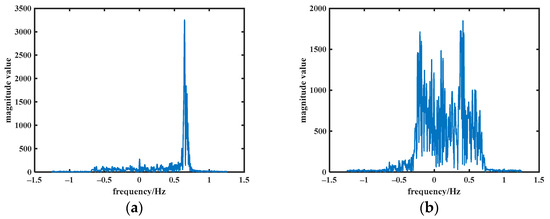
Figure 1.
Echo signal magnitude–frequency plot in altimeter (a) search mode and (b) tracking mode.
We wanted to reduce the complexity of the altimeter’s operation by performing in-orbit calibrations in tracking mode. Calculating and calibrating the altimeter-recorded I/Q data makes the calibration results more intuitive and accurate. This requires that the transponder needs to be deployed offshore, resulting in land echoes and the forwarding signals from the transponder appearing in the altimeter tracking window at the same time, as shown in Figure 1b. So, unlike the signal matching in altimeter search mode of Wan et al., at this point, the transponder forwarding signal needs to be separated from other strong scatterer echoes. There is no existing solution, to our knowledge, to match the altimeter observations and transponder observations in the calibration of altimeter tracking mode. This paper gives a method to separate the surface echoes from the transponder forwarding signals and concurrently accomplish the matching of the altimeter data with the transponder data in tracking mode.
2. Background
2.1. Altimeter
The HY-2 series satellite radar altimeter normally operates in tracking mode and measures sea surface height in a pulse-limited manner. The echo waveform data are obtained by transmitting a Linear Frequency Modulation (LFM) signal and tracking the received sea surface echo, and then the sea surface height is extracted after pulse compression and retracking techniques. A model-compatible tracker [16] is used in the altimeter for the tracking of echoes. In this tracker model, a parallel tracking algorithm of SMLE and Offset Centre of Gravity (OCOG) is used and data fusion processing is performed to achieve the goal of sea–land compatible tracking. Figure 2 shows a diagram of the altimeter echo signal with the two tracking algorithms. The power spectrogram of the ground echoes influences the selection of the locations for subsequent experiments. If the experiment is conducted at a location with an echo power spectrogram like that in Figure 2a, there will be no way to know whether the transponder forwarding signals enter the altimeter tracking window when carrying out the experiment, and it will not be possible to distinguish the transponder forwarding signal.
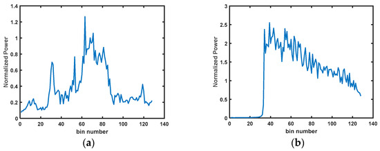
Figure 2.
Power spectrum of altimeter echo signal in (a) OCOG and (b) SMLE.
Previously, altimeters were required to switch their operating mode to search mode for in-orbit calibrations. This mode provides a tracking altitude setting function, which allows calibrations to be performed inland. The time interval between transmitting and receiving is sufficiently large to remove the echo signal from the Earth’s surface, but the transponder’s signal can be sent into the altimeter range window by properly presetting the signal run-time delay.
Table 1 shows a comparison of the characteristics of the altimeter in two modes of the altimeter. In the two modes, the altimeter uses an LFM signal with a time width of and a bandwidth of . A burst is formed by the combination of 12 Ku-band pulses and 4 C-band pulses. is the time interval between adjacent altimeter transmission operations, and is the time interval between the altimeter transmitting operation and the corresponding receiving operation. In search mode, both and are constants. However, they are constantly changing based on the tracking height in tracking mode, as shown in Figure 3.

Figure 3.
Schematic diagram of altimeter transmitting–receiving signals [18] in (a) search mode and (b) tracking mode.

Table 1.
Comparison of HY-2 altimeter tracking mode and search mode characteristics [17].
Table 1.
Comparison of HY-2 altimeter tracking mode and search mode characteristics [17].
| Characteristics | Tracking Mode | Search Mode |
|---|---|---|
| Length of tracking window/m | 120 | 240 |
| Ground command switching | No | Yes |
| Preset tracking height | No | Yes |
2.2. Transponder
Conventional bent-pipe transponders consist of an antenna, an amplifier, a microwave delay device and the necessary connecting devices, and thus do not have the capability to set different retransmission delays for different signals. The reconstructive transponder can compensate for this shortcoming. Under this system, delay, amplification and forwarding are no longer realized in only the Radio Frequency (RF) stage, but the RF signal is first de-chirped, down-converted, amplified, filtered, demodulated, etc., to generate the I/Q signals of the baseband and processed digitally. The delay is accomplished in the computer control unit, which improves the flexibility and accuracy. The working principle is shown in Figure 4.
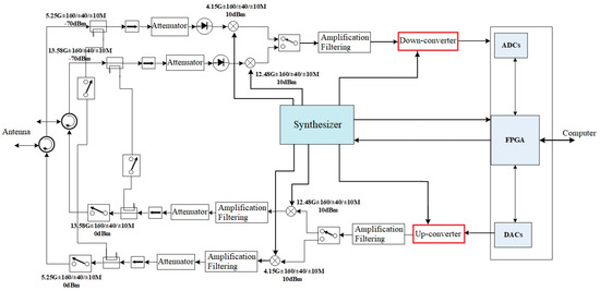
Figure 4.
Block diagram of the reconstructive transponder [15].
Furthermore, the transponder tracks the altimeter signal by means of an α-β tracking loop filter [19], whose output is accompanied by a noise of random character, and the transponder subsequently processes the fluctuations introduced by this noise to transform them from frequency errors to time errors. Therefore, there are fluctuations in the received signal data of the altimeter. However, the data from the transponder also record this fluctuation value. So, it is possible to compensate for the fluctuations in the altimeter-received data by finding a one-to-one correspondence between the fluctuations in the altimeter-received signal data and the data recorded by the transponder.
The traditional altimeter in-orbit calibration experiment needs to be switched to the search mode. At this time, the altimeter signal will be given a fixed transmitting–receiving interval, as in Figure 3a. To achieve the effect of separating the ground signal from the transponder’s forwarding signal, the signal delay value that should be assigned to the transponder is then determined based on the height of the satellite in transit of the orbit forecast. However, in the altimeter tracking mode, the transmitting–receiving interval of the altimeter signal is determined according to the tracking state of the altimeter itself, and is therefore variable, as shown in Figure 3b.
Therefore, different operations must be performed on the transponder according to the timing variations of the altimeter. To guarantee that the forwarding signal appears in the trailing edge of the sea surface echo signal, the transponder setting the delay time of the forwarding signal must also make sure that the forwarding signal enters the altimeter’s tracking window and does not affect the rising edge of the sea surface echo signal, which is the altimeter’s tracking point and determines the transmitting–receiving intervals of the altimeter signals. In practice, to achieve the above purpose, the transponder will forward the signal delay by adding a pulse time width, resulting in the first pulse being empty, and the transponder starts forwarding the signal from the second pulse.
3. Principle and Algorithm
Figure 5 illustrates the link between the transponder and satellite positions. From Figure 5 and [12], when the position of the transponder, the satellite orbit, velocity and altitude are determined, according to the cosine theorem, the distance between the transponder and the satellite altimeter is a parabolic function with time as the variable. The equation is given by (1):
where is a constant.
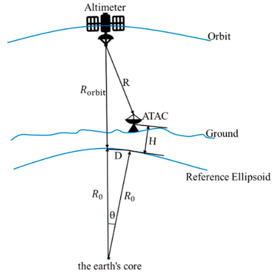
Figure 5.
Plot of the position of the transponder and the satellite ( is the height of the transponder relative to the Earth’s reference ellipsoid; is the Earth’s radius; is the relative distance between the altimeter and transponder; is the altimeter’s flight height relative to the reference ellipsoid; is the surface distance from the transponder to the satellite’s nadir; is the geocentric tensor angle corresponding to the distance from ; and is the satellite’s velocity along the orbit).
In order to control timing deviations introduced by the fixed size of the clock pulses, the transponder employs a two-stage time measurement mechanism [17]. The first level of the time measurement is realized by clock pulse counting, and the second level of the time measurement is realized by frequency measurement and modulation. Therefore, the LFM signal generated by the Direct Digital Frequency Synthesizer (DDS) is modulated with a certain frequency bias. The value of the frequency bias is equal to the signal frequency after de-chirping of the received signal. This frequency bias is the fluctuation introduced in the distance of the altimeter observation by the transponder forwarding the signal. A schematic of the geometric position of the transmitting and receiving signals when the altimeter is observing the target is given in Figure 6.
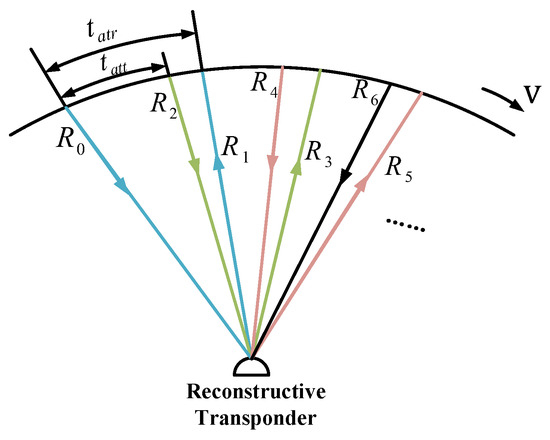
Figure 6.
Schematic of the geometric position of the transmitting and receiving signals when the altimeter is observing the target.
is the distance from the altimeter-transmitted signal to the transponder. is the distance at which the altimeter receives the signal forwarded by the transponder. The altimeter transmits signals at time , and the signals reach the transponder at time . The following equation can be defined:
where is the speed of light, .
Both the transponder and the altimeter use an LFM signal with a time width of and a bandwidth of . The frequency modulation rate can be expressed as follows:
Frequency deviation can be derived by performing FFT calculation on the transponder-recorded signal data. Combined with (3), is
Since both the altimeter and the transponder use de-chirping to process the LFM signal, then the altimeter receives signals at time , which can be expressed as
where is the delay set by the transponder and is constant in each experiment.
Hence, the equation for the transponder forwarding signal received by the altimeter is as follows:
where is carrier frequency.
So, only by finding the correspondence between (4) and (6), the fluctuating value introduced in the altimeter observation distance can be eliminated. Also, from (1), the altimeter observation distance after eliminating the fluctuations approximates a parabolic shape.
And the expression for other objects’ echoes on the ground received by the altimeter is as follows:
where is the distance between the altimeter and objects. Due to the unpredictable nature of , the other objects’ echoes will display randomness after overlaid correction is applied. In this way, the transponder forwarding signal can be separated from the clutter.
The specific implementation of the algorithm is given by the block diagram shown in Figure 7. The acquired altimeter signals and transponder signals are converted to the frequency domain by FFT processing. We looked in advance at the amplitude–frequency figures of the sea surface echoes around the experimental site. The threshold can be set to the maximum of the amplitude of the sea surface echoes. The frequency values corresponding to amplitudes greater than the set threshold in the frequency domain of the altimeter signal can be intercepted (the frequency values corresponding to the echo signal should be included in the intercepted data) and converted into distances. The signal path values acquired by the altimeter are combined with the distance fluctuation values generated by the transponder, following a chronological sequence corresponding to the transponder’s stored data. Subsequently, the data are recorded and represented graphically as a scatter plot.
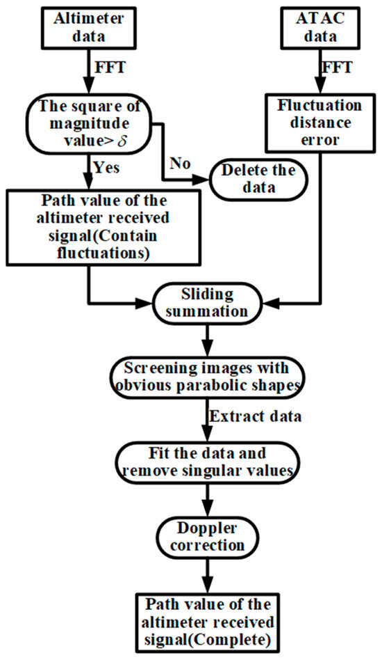
Figure 7.
Flowchart of the matching method between the altimeter-received data and the transponder data.
Each output dataset is evaluated discriminatively. Outliers are removed from the data before performing fitting operations. Finally, the calculation of root mean square error (RMSE) is utilized as the criterion for decision-making. The dataset corresponding to the minimum RMSE is output. Subsequent fitting is required to remove singularity values by narrowing the difference between the fitted curve and the true parabola until a smooth parabola is obtained.
4. Experiment and Results
In-orbit calibration transponders should be deployed at locations where the power spectral pattern of the echo signal approximates the Brownian model [20], as shown in Figure 2b. If the power spectrum of the echo signal near the calibration point is cluttered, as shown in Figure 2a, the transponder forwarding signal will be flooded. It will be impossible to judge whether the transponder forwarding signal enters the altimeter tracking window during the experiment; the subsequent data processing will not be able to separate the forwarding signal, and the uncertainty will increase. Consequently, we investigated the state of the altimeter’s echo signals within a 40 km radius of the coasts of numerous islands along China’s coastline. Furthermore, it should be noted that the transponder is stored in Beijing. A remote experimental site will result in longer travel times, which raises the possibility of equipment damage. Finally, three experimental locations were selected for the calibration of the HY-2B (37.4106101075°N, 122.6583330748°E), HY-2C (37.4426472243°N, 121.7561883854°E) and HY-2D (37.6858872379°N, 120.2710782643°E) satellites, respectively.
Take the data obtained from the in-orbit calibration experiment on 6 March 2023, for HY-2B (Pass No. 181); 25 August 2023, for HY-2C (Pass No. 114); and 8 March 2023, for HY-2D (Pass No. 166) as examples. The red line segment in Figure 8 indicates the transponder forwarding the signal into the receiving window of the altimeter. The altimeter flight distance is given in the figure from the time the transponder forwards the signal into the tracking window until the altimeter lost lock.

Figure 8.
Location of the HY-2B/C/D in-orbit calibration experiment.
During the flight phase of the satellite in the red part of Figure 8, the power spectrum of the echo signal received by the altimeter is shown in Figure 9. The signals in the red part in the figure are the forwarding echoes from the transponder. From Figure 9, the power of the transponder forwarding signal is higher than the power of the point sea surface echo under the satellite, but it does not destroy the ocean surface echo that obeys the Brown model. Therefore, the point target signal generated by the transponder is easier to recognize in the echo power spectrum under SMLE tracking mode.
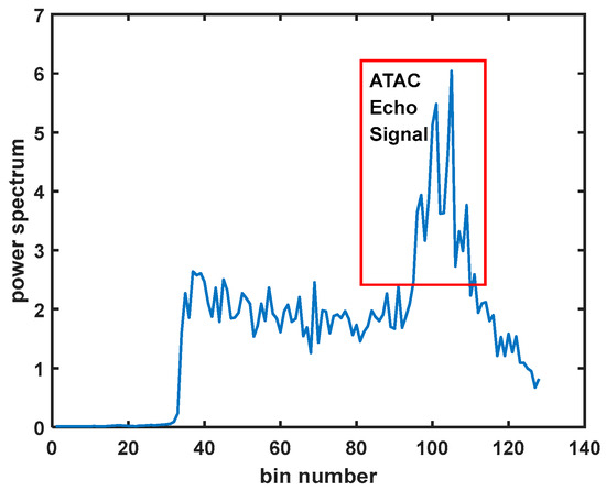
Figure 9.
Power spectrum of altimeter echo signal.
The raw I/Q data of the echo signal received in the red region of the altimeter flight in Figure 8 were processed. A threshold discrimination was set for the frequency domain signal amplitude by time–frequency variation, as shown in Figure 10. Data signals with amplitude values greater than were computed to obtain the altimeter’s transmitting–receiving two-way path values (including fluctuations).
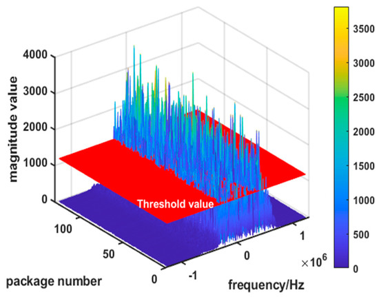
Figure 10.
Magnitude–frequency plot of altimeter baseband signal threshold settings.
The transponder is required to establish a tracking state to the on-board radar altimeter during the initial phase of the calibration experiment. The transponder does not send signals to the altimeter during this period; it only receives signals from the altimeter. Only after the tracking state has been successfully established and stabilized does it start transmitting signals to the altimeter. Consequently, the number of forwarding signals received by the altimeter is less than the number of signals received by the transponder. As a result, the length of the data recorded by the transponder is kept constant during subsequent processing, and the received signal path of the altimeter and the distance fluctuation data recorded by the transponder are added up in chronological order while sliding.
A schematic of the signal two-way distance of HY-2B/C/D before and after eliminating the distance fluctuations is given in Figure 11. As can be seen in Figure 11a,d,g and Figure 11b,e,h, the parabolic shape of the packet in the latter is more continuous and very distinct, which is consistent with the distance model between the altimeter and the transponder in (1). Figure 11b,e,h show that the matching is completed, while the distance fluctuation introduced by the forwarding signals due to the transponder is eliminated.
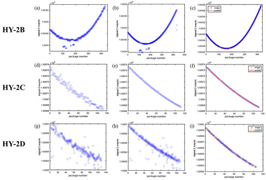
Figure 11.
Two-way path of altimeter’s transmitting–receiving signal (a,d,g) before matching, (b,e,h) after matching and after clutter removal (c,f,i).
The data extracted after the threshold setting in Figure 10 contain not only the transponder forwarding signal but also the high Radar Cross Section (RCS) targets on the ground. Thus, although the fluctuations in the altimeter echo signals introduced by the transponder forwarding signals have been eliminated in the data processing process described above, there will still be uncanceled ground echoes. As shown in Figure 11b,e,h, in addition to the data points forming a parabola, there are many data points scattered in the figure. Therefore, it is necessary to separate the ground echoes from the transponder forwarding signals by fitting and eliminating singular values. A schematic diagram of the bi-directional path of the HY-2B/C/D altimeter transmitting–receiving signal after separating from the ground echoes is given in Figure 11c,f,i. At this point, the compensation of the altimeter observation distance parabola is completed. This operation eliminates the fluctuations in the signal distance parabola due to the transponder forwarding the signal.
We achieved consistent results in multiple experiments conducted in March and August 2023 utilizing this approach. The RMSE is used to measure the difference between the matched altimeter and transponder identified by the proposed method as shown in Table 2. The corresponding visualization picture is shown in Figure 12. By combining Figure 12 and Table 2, it is evident that the RMSE of the altimeter observation distance is substantially decreased after transponder distance adjustment.

Table 2.
Comparison of RMSE before and after altimeter signal range compensation.
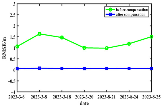
Figure 12.
RMSE of parabolic fluctuations in altimeter distance before and after compensation for successive experiments.
The RMSE before matching was bigger and the range of numerical fluctuation was greater due to the influence of ground echoes and the distance fluctuations caused by the transponder forwarding signal. On the contrary, the RMSE after matching was reduced from meters to centimeters, and the results of several experiments were stabilized at about 0.0623 m.
After removing outliers from Wan’s results [12], the calculated RMSE is roughly around 0.0895 m. Unlike Wan’s approach, our method exhibits smaller RMSE variations across numerous experiments. And there are individual unreliable matches in his results. So, combined with Table 2, it is proven that the signal matching method proposed in this paper is feasible and effective. Accurate data support was provided for the subsequent calculation of altimeter clock bias.
5. Conclusions
When the altimeter is calibrated in the SMLE tracking mode, the transponder is deployed along the coastline, and it is inevitable that ground clutter will enter the tracking window of the altimeter. Therefore, this paper gives a method to separate the transponder forwarding signal from the ground echo signal. This method can eliminate the distance fluctuation introduced by the transponder forwarding signal in the received signal of the altimeter while processing, so the calibration accuracy can be improved. The signal ranging error is decreased from the meter level to the centimeter level. We achieved consistent results in multiple experiments conducted in March and August 2023 utilizing this approach. The RMSEs after matching several experiments are stabilized at about 0.0623 m. So, the signal matching method is feasible and effective. Moreover, the scheme in this paper only relies on the altimeter observation distance and the transponder observation distance without relying on the corresponding time code, so interference of the time-scale bias in the altimeter data and the transponder data can be avoided. Moreover, the fundamental ideas that form the basis of this technology can be applied to any transponder capable of modifying the delay in its response signal during the calibration. It has established a foundation for later ground-based construction of a permanent station.
Author Contributions
Conceptualization, Q.F. and W.G.; methodology, Q.F. and W.G.; software, T.W.; validation, Q.F., W.G. and C.W.; formal analysis, W.G., C.W., P.L. and Y.Z.; investigation, Q.F., S.H. and S.Y.; resources, H.P., C.M., B.M. and Y.Z.; data curation, Q.F., S.H., S.Y. and Y.Z.; writing—original draft preparation, Q.F.; writing—review and editing, Q.F., W.G., C.W. and S.H.; visualization, Q.F. and T.W.; supervision, H.P., C.M. and B.M.; project administration, W.G. and C.W.; funding acquisition, W.G. and C.W. All authors have read and agreed to the published version of the manuscript.
Funding
This research is based on the “Twelfth Five-Year Plan” Ocean Observing Satellite Ground System Project—Development of Reconstructive Transponder for Radar Altimeter—and supported by the National Development and Reform Commission; the funding number is Y8C01FAC00.
Data Availability Statement
Data are contained within the article.
Acknowledgments
The authors thank the National Satellite Ocean Applications Service (NSOAS) for providing HY-2D altimeter level 0 data support.
Conflicts of Interest
The authors declare no conflicts of interest.
References
- Pesec, P.; Sünkel, H.; Windholz, N. The Use of Transponders in Altimetry. In Gravity and Geoid: Joint Symposium of the International Gravity Commission and the International Geoid Commission; Sünkel, H., Marson, I., Eds.; Springer: Berlin/Heidelberg, Germany, 1995; Volume 113, pp. 394–400. [Google Scholar]
- Mertikas, S.P.; Donlon, C.; Mavrocordatos, C.; Piretzidis, D.; Kokolakis, C.; Cullen, R.; Matsakis, D.; Borde, F.; Fornari, M.; Boy, F.; et al. Performance evaluation of the CDN1 altimetry Cal/Val transponder to internal and external constituents of uncertainty. Adv. Space Res. 2022, 70, 2458–2479. [Google Scholar] [CrossRef]
- Mertikas, S.P.; Donlon, C.; Kokolakis, C.; Piretzidis, D.; Cullen, R.; Féménias, P.; Fornari, M.; Frantzis, X.; Tripolitsiotis, A.; Bouffard, J.; et al. The ESA Permanent Facility for Altimetry Calibration in Crete: Advanced Services and the Latest Cal/Val Results. Remote Sens. 2024, 16, 223. [Google Scholar] [CrossRef]
- Mertikas, S.P.; Donlon, C.; Féménias, P.; Mavrocordatos, C.; Galanakis, D.; Tripolitsiotis, A.; Frantzis, X.; Tziavos, I.N.; Vergos, G.; Guinle, T. Fifteen Years of Cal/Val Service to Reference Altimetry Missions: Calibration of Satellite Altimetry at the Permanent Facilities in Gavdos and Crete, Greece. Remote Sens. 2018, 10, 1557. [Google Scholar] [CrossRef]
- Garcia-Mondéjar, A.; Fornari, M.; Bouffard, J.; Féménias, P.; Roca, M. CryoSat-2 range, datation and interferometer calibration with Svalbard transponder. Adv. Space Res. 2018, 62, 1589–1609. [Google Scholar] [CrossRef]
- Guo, W.; Gong, X.-Y.; Xu, X.-Y.; Liu, H.-G.; Xu, C.-D.; Du, Y.-H. A transponder system dedicating for the on-orbit calibration of China’s new-generation satellite altimeter and scatterometer. In Proceedings of the 2011 IEEE CIE International Conference on Radar, Chengdu, China, 24–27 October 2011; pp. 22–25. [Google Scholar]
- Wang, C.; Guo, W.; Zhao, F.; Wan, J.; Xu, K. Development of the reconstructive transponder for in-orbit calibration of HY-2 altimeter. In Proceedings of the 2015 IEEE International Geoscience and Remote Sensing Symposium (IGARSS), Milan, Italy, 26–31 July 2015; pp. 3645–3648. [Google Scholar]
- Xu, X.-Y.; Guo, W.; Liu, H.-G.; Shi, L.-W.; Lin, W.-M.; Du, Y.-H. Design of the interface of a calibration transponder and an altimeter/scatterometer. In Proceedings of the 2011 IEEE International Geoscience and Remote Sensing Symposium, Vancouver, BC, Canada, 24–29 July 2011; pp. 953–956. [Google Scholar]
- Wan, J.; Guo, W.; Zhao, F.; Wang, C.; Liu, P. HY-2A Radar Altimeter Ultrastable Oscillator Drift Estimation Using Reconstructive Transponder with Its Validation by Multimission Cross Calibration. IEEE Trans. Geosci. Remote Sens. 2015, 53, 5229–5236. [Google Scholar] [CrossRef]
- Wang, C.; Guo, W.; Zhao, F.; Wan, J.; Liu, P.; Lin, M.; Peng, H.; Xu, C. Development of the Reconstructive Transponder for In-Orbit Calibration of HY-2A Altimeter. IEEE J. Sel. Top. Appl. Earth Obs. Remote Sens. 2016, 9, 2709–2719. [Google Scholar] [CrossRef]
- Wan, J.; Guo, W.; Zhao, F.; Wang, C. Echo signal quality analysis during HY-2A radar altimeter calibration campaign using reconstructive transponder. In Proceedings of the 2015 IEEE International Geoscience and Remote Sensing Symposium (IGARSS), Milan, Italy, 26–31 July 2015; pp. 3652–3654. [Google Scholar]
- Wan, J.; Guo, W.; Wang, C.; Zhao, F. A Matching Method for Establishing Correspondence between Satellite Radar Altimeter Data and Transponder Data Generated during Calibration. IEEE Geosci. Remote Sens. Lett. 2014, 11, 2145–2149. [Google Scholar]
- Xu, K.; Liu, P.; Tang, Y.; Yu, X. The improved design for HY-2B radar altimeter. In Proceedings of the 2017 IEEE International Geoscience and Remote Sensing Symposium (IGARSS), Fort Worth, TX, USA, 23–28 July 2017; pp. 534–537. [Google Scholar]
- Wang, C.; Guo, W.; Liu, P.; Wang, T.; Cui, H. In-Orbit Calibration and Validation of HY-2B Altimeter using an Improved Transponder. In Proceedings of the IGARSS 2020—2020 IEEE International Geoscience and Remote Sensing Symposium, Waikoloa, HI, USA, 26 September–2 October 2020; pp. 5819–5822. [Google Scholar]
- Wang, C.; Guo, W.; Liu, P.; Wang, T. Development and Integration Test of an Improved Transponder for Hy–2B Altimeter. In Proceedings of the IGARSS 2020—2020 IEEE International Geoscience and Remote Sensing Symposium, Waikoloa, HI, USA, 26 September–2 October 2020; pp. 5862–5865. [Google Scholar]
- Xu, K.; Jiang, J.; Liu, H. A new tracker for ocean-land compatible radar altimeter. In Proceedings of the 2007 IEEE International Geoscience and Remote Sensing Symposium, Barcelona, Spain, 23–28 July 2007; pp. 3825–3828. [Google Scholar]
- Wan, J. Study on HY-2 Altimeter System Delay In-Orbit Absolute Calibration Using Reconstructive Transponder. Ph.D. Thesis, The University of Chinese Academy of Sciences and National Space Science Center, Chinese Academy of Sciences, Beijing, China, 2015. [Google Scholar]
- Cui, H.; Guo, W.; Wang, C.; Wang, T. In Orbit Test of Clock Frequency Deviation of HY-2B Satellite Radar Altimeter based on Transponder. Remote Sens. Technol. Appl. 2021, 36, 581–586. [Google Scholar]
- Kalata, P.R. α-β target tracking systems: A survey. In Proceedings of the 1992 American Control Conference, Chicago, IL, USA, 24–26 June 1992; pp. 832–836. [Google Scholar]
- Brown, G. The average impulse response of a rough surface and its applications. IEEE J. Ocean. Eng. 1977, 2, 67–74. [Google Scholar] [CrossRef]
Disclaimer/Publisher’s Note: The statements, opinions and data contained in all publications are solely those of the individual author(s) and contributor(s) and not of MDPI and/or the editor(s). MDPI and/or the editor(s) disclaim responsibility for any injury to people or property resulting from any ideas, methods, instructions or products referred to in the content. |
© 2024 by the authors. Licensee MDPI, Basel, Switzerland. This article is an open access article distributed under the terms and conditions of the Creative Commons Attribution (CC BY) license (https://creativecommons.org/licenses/by/4.0/).