Abstract
This paper evaluates the Arable Mark 2 sensor, an automated and low-cost radiometer, for its potential to retrieve surface reflectance data and validate orbital sensors such as the Landsat-8 (L8) Operational Land Imager (OLI) Level 2 product. While orbital sensors are widely used for monitoring solar radiation changes, managing natural resources, and understanding climatic trends, atmospheric effects can make it challenging to obtain accurate measurements. Equipped with multiple sensors, including long-wave and short-wave radiometers, the Arable Mark 2 sensor can measure upwelling and downwelling irradiance to calculate surface reflectance. To assess the accuracy and consistency of the Arable Mark 2 sensor, the study performed a cross-calibration using a ground truth measurement collected with the Analytical Spectral Device (ASD) as the reference point. Additionally, a spectral band adjustment factor (SBAF) was applied across the calibrated Arable surface reflectance to compare it against the orbital sensor. An automated library aided in calculating SBAF for the days with unavailable hyperspectral data. The study found that the Arable Mark 2 sensor can provide accurate surface reflectance data that can be used for orbital sensor validation. The Arable sensor was successfully calibrated against the ASD FieldSpec with an average difference of less than 1/10 reflectance unit (reflectance unit = 0.01) for the blue, green, yellow, and red bands. The red-edge and NIR-1 bands showed an average difference of less than 1/2 reflectance units, while the NIR-2 band had an average difference of less than 1/10 reflectance unit of calibration accuracy. The calibrated Arable surface reflectance data was then compared against orbital sensor surface reflectance data, and the results showed good agreement between the two datasets. The study concludes that the low-cost and automated nature of the Arable Mark 2 sensor makes it a promising tool for surface reflectance retrieval and orbital sensor validation.
1. Introduction
Orbital sensors extensively have been used to monitor the long-term trends and changes in solar radiation in a variety of applications such as solar energy, space weather, climate, and agriculture. By measuring these changes in solar radiation orbital sensors can aid to manage Earth’s natural resources, understand climatic trends, and can even act as a precursor to natural disasters such as droughts, floods, and wildfires. Orbital sensors measure these changes from solar radiation incident at the Earth’s atmosphere by measuring the radiation reflected or emitted at various wavelengths. The atmosphere’s constituent particles may scatter or absorb the radiation passing through the atmosphere such as aerosols, ash, etc. or by gases such as water vapor, carbon dioxide, and ozone, etc. The orbital sensors measure radiation using a two-dimensional array of pixels in a digital image with an intensity value known as its Digital Number (DN). The first step before using any remotely sensed data in quantitative studies is to convert the pixel values into physically meaningful units (e.g., top-of-atmosphere (TOA) radiance or reflectance), which is done through a process known as radiometric calibration. The second step is the atmospheric correction. Atmospheric correction is a process in which the TOA reflectance received by sensors is converted to surface reflectance (removes the scattering and absorption effects from the atmosphere) [1,2,3,4].
Historically, radiometric calibration was focused on the TOA reflectance, which included atmospheric effects. TOA reflectance can be used to gather the information for several applications, but it is generally less reliable and less accurate because it includes the effects of the atmosphere. The atmosphere can scatter and absorb incoming radiation, which can make it difficult to interpret the data and obtain accurate measurements. Additionally, the atmosphere can vary greatly depending on factors such as weather and season, which can introduce uncertainty and make it difficult to compare measurements over time. Various researchers have computed atmospheric corrections to adjust for the atmospheric effects, however, this has resulted in notable discrepancies in the estimated reflectance values for identical targets because of the different methods they used to calculate atmospheric correction. Therefore, the current scientific community has deviated from TOA reflectance towards surface reflectance (SR). There are several challenges when working with the calibration and validation of surface reflectance of orbital sensors, such as infrequent data, high cost of equipment, and heavy use of human resources. However, modern state-of-the-art technologies are working their abilities to mitigate these challenges. One example of this is the Arable platform’s Arable Mark 2 sensor, which is a prime discussion throughout the study.
Arable is a data analytical company in the field of agriculture that helps achieve economic stability, to reduce environmental footprints, and to aid in making agricultural operational decisions. The Arable Mark 2 Sensor was deployed as an instrument of calculating crop yield and to aid in supply chain decisions. Agricultural benefits aside, the Arable Mark 2 sensor is equipped with a rugged design to endure all weather conditions, global cellular connectivity, and sensors that measure climate data streams. In addition, the solar powered sensor is also equipped with an acoustic disdrometer for precipitation measurements, long-wave, and short-wave radiometers to measure upwelling and downwelling irradiance, spectrometer for six bands, and equipped with GPS facilities [5]. Although the Arable Mark 2 Sensor is equipped with numerous data collection sensors, this study primarily focuses on the long-wave radiometer/infrared temperature sensor, and shortwave radiometer/spectrometer to collect upwelling and downwelling irradiance [6,7].
By using upwelling and downwelling radiation () measurements to surface reflectance, this data can then be utilized for validating and calibrating the measurements obtained from orbital sensors. Orbital Sensors are calibrated on the ground before launch but, because of rigorous space conditions, calibration drift can occur. There are two ways of countering this problem: having on-orbit calibration systems or using in situ methods for orbital sensor validation. On-orbit calibration can be a costly method, creating an enormous demand for orbital sensor validation using in situ measurements. RedCalNet, Aeonet, and Fluxnet are all networks of ground-based sensors that collect in situ measurements of environmental variables such as radiation, temperature, and humidity. These networks can be used to validate and calibrate measurements obtained from orbital sensors. While these in situ measurement sites provide valuable data for validating SR data, they can be expensive to operate and maintain. Therefore, absolute radiometric calibration can be a cumbersome process; however, state-of-the-art technologies from the Arable platform overcomes this difficulty because of its low-cost and the automated nature of the sensor which allows level 2 product validation without people on the field. Low-cost devices like Arable can provide complementary data and help to fill in gaps in validation efforts. However, it’s important to note that there may be some differences in the accuracy and precision of measurements obtained from low-cost devices compared to more expensive instruments deployed at sites like RadCalNet.
Within the context, the objective of this paper is to evaluate an automated, low-cost in situ measurement radiometer (Arable Mark 2 sensor) to provide accurate Surface Reflectance data consistently over time. In addition, the assessment of the potential of this surface reflectance retrieval to be used for Orbital Sensor’s validation Landsat-8 Operational Land Imager Level 2 product is also performed.
In order to compare the Arable Mark 2 surface reflectance (SR) with the orbital sensor SR product, a cross-calibration was performed using a ground truth measurement collected with the Analytical Spectral Device (ASD). The ASD is considered as the gold standard for measuring surface reflectance, making it a reliable reference point for the cross-calibration process. The surface reflectance (SR) of the Arable Mark 2 after calibration was compared with the orbital sensor SR product, using a Spectral Band Adjustment Factor (SBAF) to adjust the spectral response of the sensors [8]. However, the calculation of the SBAF correction requires hyperspectral data, which is not available for every orbital sensor overpass. To overcome this limitation, an automated hyperspectral profile is created using multispectral Arable data. The SBAF is then calculated with the aid of the automated hyperspectral profile. The results demonstrate that the use of an automated hyperspectral profile is effective in addressing the issue of unavailability of hyperspectral data for the calculation of the SBAF correction. The findings also highlight the importance of uncertainty analysis in assessing the comparability of SR products from different sensors. Overall, the study provides insights into the challenges and potential solutions for cross-calibration of SR products from different sensors, which has significant implications for remote sensing applications.
The paper is organized into several sections. Section 2 provides detailed information about the study area, which includes Brookings, SD and Arlington, SD, as well as information about the Arable, Analytical Spectral Device (ASD), and Landsat Operational Land Imager (OLI) sensors. Section 3 outlines the methodology used in the study. Section 5 and Section 6 present the results of the study and draw conclusions based on the findings.
2. Materials
2.1. Study Areas
The Arable sensors evaluated in this study are located in three sites (see Figure 1). These sites were chosen mainly because of the different vegetation cover types on each site. Therefore, the sensors cover a range of reflectance measurements from corn, soybean, grass, to alfalfa land cover types, which maintains the uniformity in each region of interest of the site. In addition, these sites are located close to South Dakota State University (base of operation) which helps to collect ASD reflectance during satellite overpasses swiftly and also helps to carry out bi-weekly sensor maintenance. There are 4 sensors in the Arlington site, 3 sensors in the North Airport site, and 2 sensors in the Research Park site, which are illustrated by Figure 1, respectively. For more information about the site locations, refer Table 1.
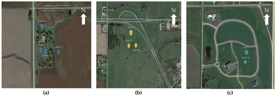
Figure 1.
Google Earth Images of the locations of the selected sites with sensor IDs: (a) 4 Sensors Deployed at Arlington Site with Grass and Corn/Soybean Land Coverage; (b) 3 Sensors deployed in North Airport Site with Grass Land Coverage; (c) 2 sensors deployed in Research Park with Alfalfa Land Coverage.

Table 1.
Ground Truth Site’s Information for the L8 OLI L2 C2 product validation.
2.2. Arable Mark 2 Sensor
The Arable sensor system is simple to deploy and employ in-the-field (see Figure 2a–c) to gain data in real time and communicate it to the user through on-board satellite links. The sensor’s comprehensive set of measurements includes data related to the (a) climate (temperature, precipitation, pressure, humidity, etc.); (b) plant (normalized difference vegetation index, chlorophyll index, crop water deficit, leaf wetness, etc.); and (c) soil and irrigation (soil moisture, soil salinity, soil temperature, etc.) [5]. Currently, the system does not directly provide surface reflectance data, which measures the fraction of incoming solar radiation reflected from the surface. Surface reflectance information is especially valuable—it is used to generate the majority of global land products from Earth Observation sensors. Surface reflectance data from Arable, however, can be derived using the upwelling and down-welling radiation () measurements according to Equation (1) [9].
where, is band specific Arable Mark 2 surface reflectance; is band specific upwelling irradiance, is band specific downwelling irradiance.
Arable data is accessible through an application program interface (API) and can be managed by users or teams for data processing and analytics. The API allows users or teams to access Arable data in mainly three-time categories: 5 min, hourly, and daily data. Throughout this research, 5 min arable irradiance data were accessed in Coordinated Universal Time (UTC) for the calculation of surface reflectance [10] and to analyze the reliability against the ASD FieldSpec SR and orbital sensor SR.
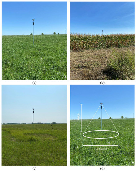
Figure 2.
Arable Mark 2 sensors deployed sites and sensor’s target area: (a) Research Park; (b) Arlington; (c) North Airport sites; (d) Target area of sensor (Adapted from Ref. [11].)
Arable data are limited to a circular target area with a diameter of twice the sensor pole’s mounted height (see Figure 2d). Pole’s mounted height will be determined according to the crop height. Technically, the pole extends up to 2–3′ higher than the maximum crop height; however, for the purpose of this study, in order to get a larger range, all the sensors were mounted at a height of approximately 8–10′ [12]. The radiometric range of the arable sensor extends up to 1200 W/m2 with an accuracy of +/−10%. Furthermore, the dependency of temperature and relative humidity accuracy ranges between +/−0.8 °C and +/−5%, respectively. In addition, the cosine response of the sensor is limited to +/−25% for the angle of incidence from 0 degrees to 75 degrees. The Arable sensor has 7 bands comprising blue, green, yellow, red, red-edge, Near Infrared (NIR)-1, and NIR-2 ranging from 420 nm to 965 nm [13].
2.3. ASD FieldSpec
ASD’s FieldSpec Pro hyperspectral spectroradiometer was used to measure the surface reflectance for the comparison of the Arable Mark 2 sensor. The FieldSpec ASD was operated manually, and the user avoided casting operator’s shadow on the measurement area by holding the collection unit vertically toward the ground (approximately 1.3 m high). The FieldSpec ASD was carried around the area using a backpack device and was set up to average 10 spectra per sample. SR measurements are taken with the handheld hyperspectral spectrometer (ASD) to cover the approximate range of the circular target area of the Arable sensor using a fiber optic probe to retrieve spectral signatures of the region of interest [14]. The hyperspectral spectrometer is limited to a 1.4 nm resolution from 350 to 1000 nm wavelength, and 10 nm resolution for the 1000–2500 nm wavelength. The output is then sampled at 1 nm intervals using a data analysis software throughout the whole spectral range [15,16,17,18,19].
The collection of SR measurement from ASD is done in 2 parts; namely, to add to the existing hyperspectral profile library (SR of the whole site) and to collect data to calibrate the Arable Sensor. Figure 3 indicate an example of the method SR measurements collected using ASD for the hyperspectral profile. All measurements are taken in +/−15 min interval during the satellite overpass. Initially, 10-sample of spectra are taken from the reference panel (white panel) to optimize the sensor. Next, measurements are taken along the rows, with each row comprising approximately 50 samples per row. For each time the operator returns to the starting line, another 10 samples of spectra are taken against the reference panel (i.e., After each even number of rows, a reference panel measurement will be taken). This process is repeated for all 8 rows and data collection is terminated with a final reference panel measurement. The same process is followed for all the sites and the area of measurement will change depending on the size of the ROI. Additionally, the measurements around the Arable sensors are also used to add to the existing library of hyperspectral profile measurements to aid surface reflectance validation of orbital sensor with respect to Arable Mark 2 Sensor.
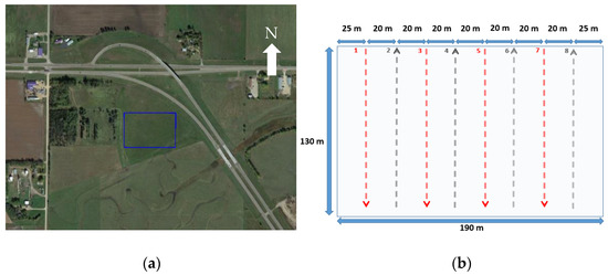
Figure 3.
Area of Interest of North Airport Site for ASD and method of SR acquisition using ASD in the region of interest: (a) Aerial view of North Airport Site ROI; (b) Illustration of the method of collecting data with an ASD FieldSpec.
2.4. Landsat L8 OLI Multispectral Surface Reflectance
On 11 February 2013, the Landsat 8 satellite, which is equipped with the OLI and Thermal Infrared Sensor (TIRS) instruments, was launched into orbit. This sun-synchronous satellite, which is situated at a height of 705 km, completes one orbit every 16 days [20]. The L8 OLI is comprised of 9 bands: namely, coastal aerosol, blue, green, red, near infrared (NIR), short-wave infrared 1 (SWIR 1), short-wave infrared 2 (SWIR 2), panchromatic, and cirrus. In addition, L8 satellite includes 2 thermal bands namely, TIRS 1, TIRS 2. Bands 1 through 7 and Band 9 of the OLI’s nine spectral bands have a spatial resolution of 30 m. Panchromatic Band 8 has a 15 m resolution. Landsat 8′s scene size is roughly 170 km north–south by 183 km east–west with a 185 km swath width. A push broom configuration, 12-bit radiometric resolution, and over 7000 detectors in each of the multispectral bands are features of the OLI sensor [2,3].
Landsat products consists of multispectral imaging data derived from DN values are delivered as a metadata file with rescaling coefficients. The data is then rescaled using the provided coefficients to generate TOA reflectance or surface reflectance to obtain the level 1 product. Succeeding Level 1 product, Landsat products offer multispectral imaging data corrected against atmospheric scattering and absorption effects to obtain the level 2 products [21,22,23,24,25]. In addition, Landsat multispectral imaging data sets consist of collection sets. Landsat collection 2 supersedes collection 1 released in 2017, with superior radiometric calibration qualities of the sensor and geometric accuracy [26,27,28]. For this study, Landsat 8 (L8) Operational Land Imager (OLI) Level 2 (L2) Collection 2 (C2) will be used for SR validation using the low-cost radiometer. Refer Table 1 for information about the site’s location, land cover type, number of overpasses per period, and ROI size.
The Arable Mark 2 sensor cannot be used to directly validate L8 OLI satellite because the relative spectral response (RSR) does not align between the instruments; in addition, the Arable Mark 2 sensor does not contain any SWIR band channels. Therefore, as a work around method, SBAF corrected hyperspectral measurements can be used to compare against any satellite. This research uses an approach of finding the closest hyperspectral measurements collected by the ASD for a certain time of the day to be compared against an Arable data set of the same time of the day. Here, an existing library from 2002–2022 of hyperspectral profile measurements collected through the ASD is used for the comparison [29,30].
3. Methodology
The aim of this research paper is to evaluate the Arable sensor and validate orbital sensors against it. However, there are several obstacles that must be overcome prior to any evaluations or validations. To evaluate the Arable sensor, it is necessary to assess the validity of the sensor and filter out erroneous data. The validity of the Arable sensor is determined by cross-calibrating it against the ASD Field Spec, which is considered the gold standard for measuring surface reflectance. During the cross-calibration process, inaccurate data caused by sensor alignment issues, unclean sensor surfaces, and cloud cover are filtered out.
In contrast, when validating orbital sensors using the Arable sensor, it is necessary to correct for differences in spectral responses between the two sensors. The Arable surface reflectance must be corrected using Spectral Band Adjustment Factor (SBAF) to bring it in line with the relative spectral response of the orbital sensor before making comparisons. Calculating the SBAF requires hyperspectral data, and since the Arable data is multi-spectral, an automated approach is introduced to find the most similar hyperspectral measurement in a library of surface reflectance taken through the ASD. The most similar hyperspectral measurement is then used to calculate the SBAF correction, which is applied to the Arable’s multispectral surface reflectance to align it with the relative spectral response of the orbital sensor’s multispectral surface reflectance.
Overall, the methodology for this research includes cross-calibrating Arable SR with ASD, filtering and calibrating Arable SR, finding the most similar hyperspectral SR to the given multispectral SR using an automated process, calculating the SBAF correction using the found hyperspectral SR, applying the SBAF correction to the Arable’s multispectral SR to align it with the relative spectral response of the orbital sensor’s multispectral SR, and finally, validating orbital sensor’s SR product with Arable SR [29,30].
3.1. Arable Mark 2 Radiometric Calibration with ASD FieldSpec
This section entails the methods used to assess the validity of the Arable sensor by comparing it against the ASD Field Spec. Figure 4 goes over the general flow of work to evaluate the SR of the Arable Sensor. There are four main steps to this process: (1) calculating cross-calibration gain; (2) fitting gain as a function of solar zenith angle for normalization; (3) normalizing for the solar zenith angle; and finally (4) calibrating arable reflectance.
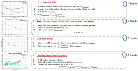
Figure 4.
Area General Flow Chart for Evaluating the SR of Arable Mark 2.
The first step for this process is to calculate the cross-calibration gain between simulated arable SR from an ASD and averaged Arable SR. Radiometric cross calibration plays a pivotal role in maintaining the accuracy and consistency of remote sensing data. This approach entails calibrating a sensor against a well-calibrated ground truth radiometer. To initiate the cross-calibration process, hyperspectral in situ data were weighted in accordance with the Spectral Response Function (SRF) of the Arable sensor to get simulated Arable SR from ASD [8]. To ensure accurate cross-calibration, it is essential to filter the arable data that is obtained through the arable API to only retain the measurements that were captured while the ASD was used to take measurements in the vicinity of the arable. Next, the Arable measurements are averaged over a 15 min interval to compare with the Simulated Arable from ASD through the cross-calibration method. Equation (2) will be used to calculate simulated Arable from ASD and Equation (3) is the ratio between simulated Arable SR from ASD and average Arable SR used as a cross calibration gain [4].
where, is simulated Arable SR from ASD; is the hyperspectral reflectance profile (in situ surface or TOA reflectance); and SRF is the Spectral Response Function [unitless].
where is the simulated Arable SR from ASD; is the Arable SR.
As requirements of cross calibration both the Arable sensor and the ASD FieldSpec should acquire the same ground target reflectance, with the same spectral bands, acquisition time, and illumination viewing geometry [31]. Here, both sensors acquire the same target and at the same acquisition time and thus viewing and solar geometry. Furthermore, by simulating the Arable SR from the ASD both sensors will have the same relative spectral response. However, in addition to the above corrections the cosine diffuser used on the top of the Arable for downwelling irradiance has an angular dependency that must be corrected for as well [32]. The next step for the process will determine the relationship between the cross-calibration gain vs. solar zenith angle, to analyze a potential linear association between the two variables. Next, using the data points, a line of best fit (predicted gain) is plotted in the cross-calibration gain vs. solar zenith angle graph. The linear fit equation is illustrated below by Equation (4). The gradient and the intercept for the linear equation are shown by Equations (5) and (6), respectively. Solar zenith angles were acquired from the time and date the ASD measurements were taken with the location’s longitudes and latitudes incorporated into the solar position algorithm for solar radiation applications [33].
where, is the solar zenith angles; is the predicted gain values ().
where, is the slope of the linear fit; are the solar zenith angles; is the observed gain values (); is the intercept of the linear fit; is the number of observations.
To ensure that the data is comparable and consistent for sensor angular effects, the third step in our research process involves correcting the data to a single selected solar zenith angle value. We accomplish this by using Equation (7) to normalize the reference gain to the selected solar zenith angle. This normalization process generates a normalized gain value that can be plotted against the zenith angle. The resulting plotted values form a flat line with a slope of 1, indicating that all normalized values are directly proportional to the gain value at the reference zenith angle. This observation reinforces that the solar zenith angles are dependent on the gain and shows a near perfect transmission. Therefore, by using the data points in the predicted linear fit, solar zenith angle corrected gain values could be obtained.
Before calibrating the Arable SR (step 4), it is necessary to first filter out any erroneous data points that may be impacted by sensor alignment, unclean sensor surfaces, and cloud cover. The following process is utilized for this filtration step (Figure 5):
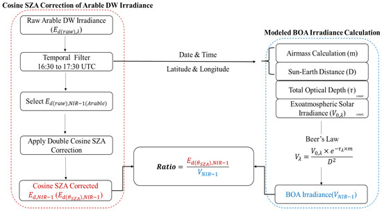
Figure 5.
Flowchart for filtering arable data sets.
It is necessary to analyze downwelling irradiance in order to understand atmospheric changes. Therefore, erroneous data can be identified from disturbances in the atmosphere or due to sensor inaccuracies of detecting downwelling irradiance. This filtration process uses the modeled bottom of the atmosphere (BOA) downwelling irradiance as a reference point to compare against cosine/solar zenith angle corrected Arable downwelling irradiance. The ratio of Arable and BOA irradiance is taken to identify potential erroneous data for a given time period. The objective of this filter is to identify a threshold ratio to sift through large and potentially irrelevant datasets by ensuring it only contains quality information.
To process the raw Arable dataset, only 5 min irradiance data within the timeframe of 16:30 to 17:30 UTC are imported from the Arable API. The airmass and sun earth distance are then calculated using mathematical algorithms [34], respectively, based on the Arable data’s date, time, latitude, and longitude. These values are substituted into Beer’s law (Equation (8)) to determine an approximate bottom of atmosphere (BOA) irradiance. An average “clear” total optical depth is used along with constant exo-atmospheric solar irradiance in the Beer’s law equation [35,36].
where, is the BOA irradiance, proportional to the solar irradiance for the wavelength ; is the exoatmosheric solar irradiance wavelength ; is the Sun–Earth distance factor in astronomical units; is the relative optical airmass; and is average “clear sky” total optical depth for the wavelength based on the Aerosol Robotic Network (AERONET) for the region the Arable is located.
The Aerosol Robotic Network level 1.5 data from 2020 to 2023 indicates that the total optical depth shows minimal variability at 870 nm, rendering it less susceptible to variations arising from aerosol, ozone, and other mixed gases. To investigate this phenomenon, we analyzed the NIR-1 band of the Arable sensor, which covers the wavelength range of 780–900 nm and includes the 870 nm wavelength. Therefore, we focused only on the temporal filtered downwelling (DW) irradiance in the NIR-1 band. Additionally, the Total Optical Depth (TOD) and exo-atmospheric irradiance are both relatively constant at 870 nm due to several factors. This particular wavelength is located in a spectral region where the Earth’s atmosphere is relatively transparent to incoming solar radiation [37]. The atmospheric constituents that absorb or scatter radiation at this wavelength, such as nitrogen, oxygen, carbon dioxide, water vapor, and aerosol are relatively constant. Furthermore, a double cosine correction is applied to the DW irradiance of the NIR-1 band. This correction compensates for the dependence on the angle of incidence, as well as the height of the pole, the sensor’s position on the pole and the cosine properties of the fuse receptor [32].
The next step involves calculating the ratio between the cosine solar zenith angle corrected DW irradiance and BOA irradiance (Equation (9)). A threshold is then applied to filter out clear days by analyzing the trends of the ratio vs. time plot. The filtered ratios are used to determine the corresponding dates, which are used for radiometric calibration of the Arable dataset in the final step of the process.
where, is cosine solar zenith angle corrected DW irradiance from NIR-1 band; is modeled BOA irradiance from NIR-1 band.
In the final step of the process, the Arable dataset is calibrated using radiometric techniques and compared to the ASD dataset. For the dates recorded in the previous filtration process, raw Arable irradiance data is imported again from the Arable API and is converted to SR using Equation (1). Next, the solar zenith angles for a specific date and time are calculated using the sun position algorithm for solar radiation applications [24] and taking into account the Arable sensor’s location (Longitude, Latitude, Altitude). Using the respective solar zenith angles, the gradient and intercept obtained in the linear fit equation from the second step the corresponding predicted gain for each and every wavelength can be found. Finally, to obtain the calibrated Arable reflectance, the predicted gain is multiplied by the newly calculated Arable SR corresponding to the solar zenith angle. Equation (10) provides additional details on how this calculation is performed.
Finally, in order to confirm the distinction between the calibrated Arable SR and the ASD, Equation (11) is employed for evaluating both sensors.
3.2. Deriving Multispectral Arable Data into Hyperspectral Data and SBAF Correction
This research paper explores the use of calibrated Arable data to verify the accuracy of OLI sensor surface reflectance data. However, direct validation is not possible due to variations in spectral bands, so the study employs the spectral band adjustment factor (SBAF) to compensate for these differences [8]. To generate the necessary hyperspectral profile for SBAF calculation, a reference hyperspectral library was created from in situ measurements conducted by SDSU over 20 years. This section describes the methodology involved in creating an automated approach to identify the optimal hyperspectral profile for daily arable reflectance information against other hyperspectral profiles. Once the appropriate hyperspectral profile is identified, the SBAF is calculated using this profile and applied to calibrated Arable SR to validate it against the orbital sensor’s SR product.
Figure 6 illustrates the step-by-step methodology that demonstrates the effectiveness of using an automated approach with a hyperspectral library to validate remote sensing data against ground truth measurements. To begin the process, the calibrated Arable is temporally filtered based on the selected orbital sensor’s overpass time and dates. On the other hand, ASD SR from the hyperspectral library is converted to simulated Arable SR using Equation (2) to bring both Arable and ASD to the same spectral domain. Next, using the temporally filtered Arable SR and simulated Arable SR, the ratio is calculated for each spectral band to determine the spectral offset. Next, the average ratio is obtained by averaging ratios across the bands per day is to radiometrically rescale to the same numerical range. The normalized ASD can then be calculated by multiplying the average ratios by the simulated ASD from Arable. This brings the ASD measurements to the same level as the Arable reflectance. Once normalized ASD measurements are obtained, the mean square error (MSE) is calculated across all bands using Equation (12). Finally, the measurement with the least MSE is selected as the closest forecast to Arable reflectance.
where, n is the number of bands Arable sensor; is calibrated Arable SR; is simulated SR.
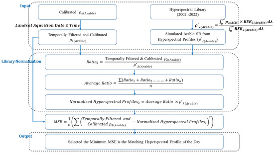
Figure 6.
Flowchart for deriving multispectral Arable data into hyperspectral data.
After determining the closest hyperspectral forecast to the Arable reflectance, the SBAF correction can be determined using Equation (13) [8].
where, is the simulated reflectance for the L8-OLI; is the simulated reflectance for the Arable Mark 2; is the hyperspectral profile of the surface (ASD); is the relative spectral response of the L8-OLI; is the relative spectral response of the Arable Mark 2.
To further explore the usefulness of the Arable sensor and extend its spectral range of coverage to sensors with bands such as the Coastal Aerosol (CA), NIR, SWIR-1, and SWIR-2 bands of the Landsat sensors were also determined. While the Arable and Landsat for these bands have no (or limited) direct spectral overlap, an SBAF anchored via the underlying hyperspectral curves that did cover these longer and shorter wavelengths were calculated and used with the Blue, NIR-1, NIR-2, and Red bands, respectively (see Figure 7). The selection of the respective spectral bands to the Arable bands was based on results that exhibit the least surface reflectance difference between them. Therefore, their respective SBAF corrections were calculated as demonstrated by Equations (14)–(17).
where, , , and are the simulated SR for L8-OLI from CA, NIR, SWIR-1 and SWIR-2 bands, respectively; , , and are the simulated SR for the Arable Mark 2 from Blue, NIR-2 and Red bands, respectively; , , are calibrated Arable SR for Blue, NIR-2 and Red bands, respectively.
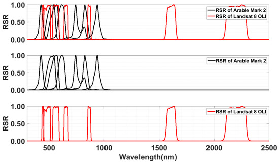
Figure 7.
Relative Spectral Responses (RSR) of Arable Mark 2 SR and L8 OLI.
3.3. Surface Reflectance Validation of Landsat 8 with Respect to Arable Mark 2 Sensor
After the SBAF calculation is completed, it is multiplied by the desired Arable measurement to enable comparison with the orbital sensor surface reflectance. The comparison is carried out by taking the difference between the orbital sensor SR and the SBAF-corrected and calibrated Arable surface reflectance and plotting it in a surface reflectance vs. time graph. Here, orbital sensor (L8 OLI) surface reflectance is calculated using the equation provided by the U.S. Geological Survey (USGS) [38].
where, , corresponds to OLI L2 SR product corresponding to band ; is the digital number (pixel value) of OLI L2 product corresponding to band ; is the multiplicative scale-factor and is the additive scale factor used to convert to SR at band .
In order to remove outliers or data points that can potentially distort results, clouds and shadows were removed from the study after the surface reflectance of the orbital sensor was calculated. This was done using the Landsat 8 Level 2 Collection 2 Band Quality Assessment (BQA) data. Each L8 image was checked for the presence of clouds, shadows, and snow using the relevant Quality Assurance (QA) band information. A bit-packed combination of dilated cloud, cirrus, normal cloud, cloud shadow, snow, cloud confidence, cloud shadow confidence, snow/ice confidence and cirrus confidence is represented as an integer number in the QA band. The Level-2 QA band pixel values had to be transformed into 16-bit binary form in order to be used properly. Through the implementation of bitwise cloud filtering from the QA band of the surface reflectance product, an image of L8 that was free of clouds, shadows, and snow was obtained [39].
Finally, for the purpose of validating the distinction between the calibrated and SBAF corrected Arable sensor’s SR and the orbital sensor (L8 OLI L2) SR, Equation (19) is utilized. The equation is expressed as:
4. Uncertainty Analysis
In order to establish the reliability of a measured value, it is imperative to conduct a quantitative assessment of the associated uncertainty. This evaluation requires consideration of uncertainties stemming from various factors. Notably, the uncertainty arising from radiometric calibration and validation is crucial in determining the reliability of calibration results. Therefore, it is of importance to emphasize the significance of reporting uncertainties in order to instill confidence in measured values.
4.1. Uncertanties in Arable Mark 2 Radiometric Calibration
Four sources of uncertainty have been identified during the process of Arable Mark 2 Radiometric Calibration with ASD FieldSpec. The gain calculation uncertainty divides into 2 parts of uncertainty from Arable Surface reflectance and uncertainty from ASD instrument at field conditions. The other two uncertainty calculations are from the final linear fit calculated from the predicted gain and the uncertainty from solar zenith angles. However, this uncertainty from the solar zenith angle calculation contains only an insignificant value; therefore, it was disregarded in the uncertainty analysis [24]. Finally, all the uncertainties are added using the ISO-Guide to the Expression of Uncertainty in Measurement (GUM) method to calculate the total uncertainty of the Arable Mark 2 Radiometric Calibration with ASD FieldSpec process [40].
The most common experiment performed to collect statistical uncertainty is performing the repeatability of the measurements. Repeatability measures the variation in successive measurements of the same variable taken under the same conditions in a short period of time. The percentage of uncertainty associated with the Arable repeatability measurement of SR is calculated using Equation (20). Here, the standard deviation (SD) and averaged Arable is calculated from the 3 measurements taken 5 min apart from a 15 min interval. Finally, the average is taken across all the ratios of SD of Arable is to average Arable SR expressed as a percentage.
The repeatability percent uncertainty from the ASD at field condition is calculated using Equation (21) illustrated below. The SD and average of 10 sample of spectra is substituted to the equations and averaged across all the ratios of SD and the average reflectance expressed as a percentage. In order to determine the uncertainty of the ASD instrument under field conditions, we followed a similar approach to the Arable uncertainty calculation. Specifically, we conducted three white panel measurements at 5 min intervals to mimic the Arable measurement protocol. This allowed us to accurately calculate the uncertainty of the ASD instrument in field conditions. In addition, since these measurements are taken at field conditions the instrument noise and atmospheric effects over the short interval will also be included in the uncertainty of the ASD instrument.
Within the field of statistics, the standard error serves as a means of evaluating the extent of variability present in measurements. In the context of the present research, the uncertainty associated with the second step of the methodology (see Section 3.1) was approximated through the standard error, as delineated in Equation (22). Moreover, in order to determine the percentage of uncertainty of the final linear fit based on predicted gain values, the average of the ratios between the standard error of the linear fit and the average gain was calculated, as expressed in Equation (23).
where : total sample size; : actual value of response variable (); : predicted value of response variable (; : actual value of predictor variable; : mean value of predictor variable.
The objective of combining uncertainties of Arable Mark 2 radiometric calibration is to evaluate the overall level of uncertainty resulting from a variety of sources of uncertainty components. In the present study, the final combined uncertainty was assessed via the ISO-GUM method. The statistical independence of the uncertainty components was assumed, as outlined in Equation (24). This approach enables an analysis of the concordance between ASD and Arable.
4.2. Uncertanties in the Automated Process for Deriving Multispectral Arable Data into Hyperspectral Data
The rationale for determining the uncertainty of the automated process is to ascertain the level of uncertainty associated with obtaining a hyperspectral measurement from the hyperspectral library through an Arable measurement. The uncertainty for the hyperspectral measurements in the automated process was calculated by randomly selecting simulated Arable SR values based on ASD measurements, with three measurements taken per year and the coefficient of variation calculated. The uncertainty of the calibrated Arable reflectance (as detailed in Section 4.1) was then combined with these values using Equation (25) to obtain the total uncertainty.
4.3. Uncertanties in Validation of Landsat 8 with Respect to Arable Mark 2 Sensor
In order to determine the reliability and accuracy of how well the orbital sensor validates against the Arable Mark 2 sensor, the computation of the overall uncertainty of validating each and every wavelength of orbital sensor (L8 OLI) is important. This is determined by incorporating the uncertainties of the calibrated Arable SR, SBAF correction, and Landsat 8 Operational Land Imager (OLI) SR, using Equation (26). In particular, the uncertainty associated with the calibrated Arable SR remains unchanged from the value employed in Section 4.1. Additionally, the uncertainty related to SBAF correction is computed based on Equation (27) below. Lastly, the temporal uncertainty of the orbital sensor (L8 OLI) SR is determined by utilizing the L8 OLI Level 1 temporal uncertainty [41].
where, : simulated L8 OLI SR; : simulated Arable SR; is the standard deviation of simulated L8 OLI SR; is the standard deviation of simulated Arable SR.
5. Results and Discussion
5.1. Arable Mark 2 Radiometric Calibration with ASD FieldSpec
As discussed in Section 3.1, after correcting the cross calibration gain to the sensor’s angular effects, our goal is to calibrate the Arable SR. However, due to large and potentially irrelevant datasets (unclear days, sensor inaccuracies) the quality of the calibration can decrease. Therefore, in order to quality control the data, irrelevant data points must be filtered out to find reliable days. For this, it is necessary to analyze downwelling irradiance in order to understand atmospheric changes. Here, Figure 8a shows the ratio of Arable raw downwelling irradiance and BOA irradiance data. Here, as discussed in the methodology Section 3.1 (Arable data set filtering step), Arable raw downwelling irradiance and BOA irradiance data ranges between 780 nm to 900 nm. After the filtering out erroneous data due to unclear days, Arable data can be cross calibrated against the ASD FieldSpec. Figure 8b shows the calibrated Arable reflectance before and after it is cross calibrated against the ASD FieldSpec.
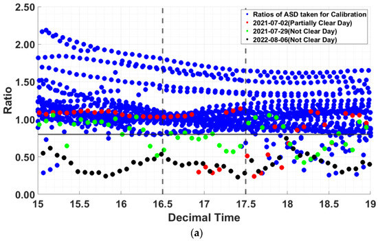
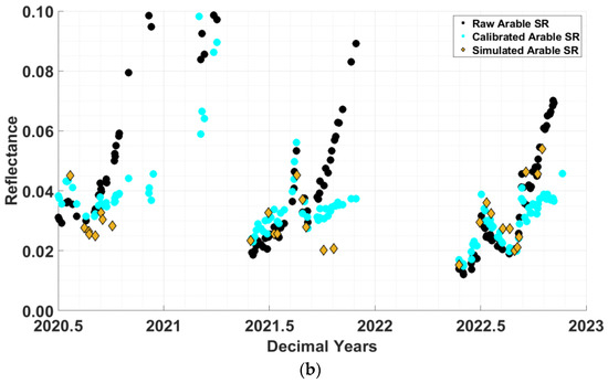
Figure 8.
Arable Radiometric Calibration with ASD FieldSpec (a) Raw Arable filtration for data impacted by unaligned sensors, unclean sensors, affected by cloud cover in the north airport site; (b) reflectance vs. time graph depicting Arable reflectance, calibrated Arable reflectance, and simulated Arable reflectance for a sensor located in the north airport site.
In order to provide a comprehensive explanation of the filtration process of the Arable SR data, the analysis only considers times between 16.5 to 17.5 UTC, which is when most satellite sensor overpass. A threshold value of 0.8 was used during this time period, and all the ratios were expected to lie above this threshold if the weather was clear. The filter used in the study was tested by plotting a few bad days on the same plot, and it was observed that the filter was successful in removing the points corresponding to cloudy days. The Aerosol Optical Depth (AOD) values obtained from the AERONET website and orbital sensor (L8 OLI) images were used to determine the presence of clouds. Moreover, the 0.8 value of threshold was determined using a trial-and-error approach according to the results of the plots for all sites which encompassed values conservatively. Additionally, it was observed that the SZA correction applied twice for arable DW irradiance measurements led to higher ratio values for the last 4 upper ratio lines (Figure 8a) in October due to the low SZA. This increase in ratio values was attributed to the increased intensity of sunlight as the sun moves closer to the zenith (winter months). In the filtration process, there is an exception where data collected during the Arable SR calibration on a clear day may be categorized as unclear due to the swift movement of clouds, which can change the clarity of the day. In Figure 8a, unclear days are indicated by the colors red, green, and black. Figure 8b displays the raw, calibrated, and simulated Arable data on the same graph. The calibrated Arable data appears to closely follow the trend of the simulated Arable data from ASD in contrast to the not calibrated Arable data. Notably, the spike in reflectance is attributed to the previously discussed increase in sun intensity during the winter months.
With the data now filtered, an analysis is performed to the average of the good data as seen in Figure 9 which presents the mean of the calibrated Arable data’s difference in surface reflectance compared to the raw Arable data against banded ASD. Here, the difference comparisons between ASD FieldSpec and the Arable sensors are analyzed band wise. Arable sensors are treated as a single platform across all sites to gain insight into the overall calibration performance of the sensors. These results demonstrate that the Arable instruments were successfully calibrated for the blue, green, yellow, and red bands with an average difference of less than 1/10 reflectance unit (reflectance unit = 0.01) with respect to ASD. Moreover, we can calibrate the red-edge and NIR-1 bands with an average difference of less than 1/2 reflectance units, with the NIR-2 band experiencing an average difference of less than 1/10 reflectance unit of calibration accuracy. Initially, raw Arable SR ranged from ½–1 reflectance unit in blue, green, yellow, red band and red-edge, NIR-1, NIR-2 showed values closer to 1 reflectance unit. Refer Table 2 for precise mean values before and after calibration.
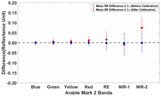
Figure 9.
Mean plot for the difference of calibrated Arable SR compared to the raw Arable SR against banded ASD.

Table 2.
Mean values for the difference of calibrated Arable surface reflectance compared to the raw Arable surface reflectance against simulated arable surface reflectance.
5.2. Deriving Multispectral Arable Data into Hyperspectral Data and SBAF Correction
In the context of multispectral Arable SR data, the primary objective is to convert it into hyperspectral data by identifying the most suitable match for the simulated arable reflectance (estimated from ASD around Arable) shape compared to the arable reflectance observed on a specific day. Figure 10 illustrates the hyperspectral surface reflectance vs. wavelength graph. The black color line represents the hyperspectral profile acquired with ASD on 16 August 2020 near the Grass A sensor(C003969) in the North Airport site; simultaneously, the red color is the hyperspectral surface reflectance on 11 October 2015 from 3M vegetation Brookings site selected as the best-fit from the automated library process (discussed in Section 3.2). This hyperspectral reflectance profile was then used for the SBAF estimation (see Section 3.2 latter). In some cases, the best-fit automated profile will give the actual hyperspectral profile acquired. Similarly, the same process will be applied to other days to obtain the best fit hyperspectral profile.
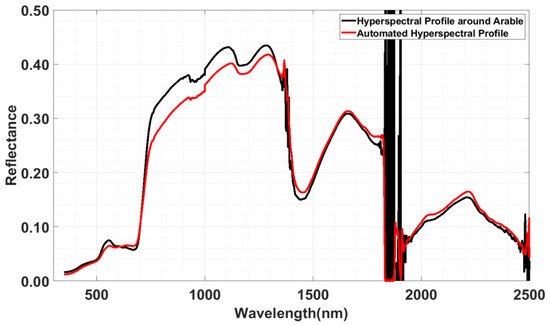
Figure 10.
Original hyperspectral profile/automated hyperspectral profile vs. wavelength plot.
5.3. Surface Reflectance Validation of Landsat 8 with Respect to Arable Mark 2 Sensor
For the final analysis of the surface reflectance difference between L8 OLI images and Arable sensors, a total of 41 L8 OLI images were selected from path and rows P029R029 and P030R029, covering the period of 2020 to 2022. The selection of these images was based on cloud/snow filtration for L8 OLI SR products and arable data filtration (see Section 3.1 and Section 3.3). Next, the Arable Mark 2 sensor and the orbital sensor (L8 OLI) have been compared extensively. Similar to the discussion in Section 5.1 where the ASD FieldSpec and Arable sensor were compared, the Arable sensors have been treated as a unified platform across all sites to evaluate the sensor’s overall calibration performance. The surface reflectance and their differences (L8 OLI and calibrated and SBAF corrected Arable) were plotted for the coastal aerosol, green, and SWIR-1 bands, as shown in Figure 11, Figure 12 and Figure 13, respectively. Notably, the SWIR-1 band exhibited higher variation (scattering data), which can be attributed to the usage of simulated Arable SR from the NIR-2 band to calculate SBAF for the SWIR-1 band, as the Arable sensor does not contain any SWIR bands in its relative spectral responses. Consequently, significant variations were observed after applying SBAFs to Arable reflectance, owing to the significantly distant RSRs between SWIR-1 and NIR-2.
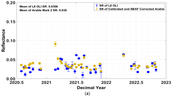
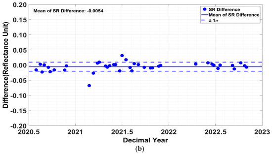
Figure 11.
Surface reflectance and its difference plotted in SR vs. time plot (a) Surface reflectance time series of CA band (b) Surface reflectance difference time series of CA band.
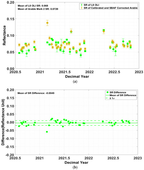
Figure 12.
Surface reflectance and its difference plotted in SR vs. time plot (a) Surface reflectance time series of green band (b) Surface reflectance difference time series of green band.
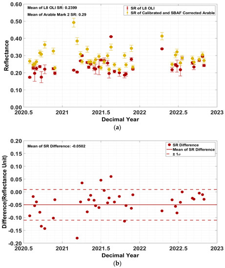
Figure 13.
Surface reflectance and its difference plotted in SR vs. time plot (a) Surface reflectance time series of SWIR-1 band (b) Surface reflectance difference time series of SWIR-1 band.
Figure 14 shows the mean SR difference between calibrated and SBAF corrected Arable SR and their standard deviations for each spectral band. Despite the Arable not having the spectral information to fully cover the CA band, the use of the SBAF and the Arable’s Blue band was extended and used validate to the CA within less than one reflectance unit. The average difference for validation using the blue, green, and red bands was less than half a reflectance unit. In the case of the NIR-2 channel and SWIR-2, we were able to validate those bands with an average difference of less than 3 reflectance units. On the other hand, the SWIR-1 channel was validated with an average difference of about 5 reflectance units in relation to the calibrated and SBAF corrected Arable SR. Refer Table 3 for precise mean values.
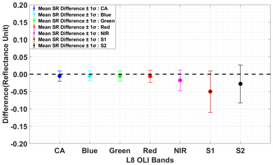
Figure 14.
Mean surface reflectance difference across all L8 OLI bands.

Table 3.
Mean and values for the difference of calibrated and SBAF corrected Arable surface reflectance compared to the L8 OLI surface reflectance.
5.4. Uncertanties in Arable Radiometric Calibration and Landsat Surface Reflectance Validation
The Arable Mark 2 Radiometric Calibration with respect to the ASD FieldSpec process underwent an uncertainty analysis using the ISO-Guide to the Expression of Uncertainty in Measurement (GUM) method [40]. This approach was used to calculate the total uncertainty, which ranged from 1% to 2% across all spectral bands (refer to Section 4.1). The Red band exhibited the lowest uncertainty of 0.83% for calibrating Arable SR, while the NIR-1 band had the highest uncertainty of 2.2%. Table 4 provides further details on these findings.

Table 4.
Total uncertainty for the Arable Mark 2 radiometric calibration.
The ISO-GUM technique was again utilized to determine the overall uncertainty level in the automated process by merging the calibrated Arable surface reflectance and simulated Arable from ASD uncertainties (refer to Section 4.2). The uncertainty of finding the best matched hyperspectral profile for Arable SR ranged from 3% to 5%, and Table 5 contains additional information.

Table 5.
Total uncertainty for the automated process.
Finally, the ISO-GUM technique was applied once more to determine the overall uncertainty level in the validation of orbital sensor (L8 OLI) surface reflectance. This involved merging the calibrated Arable surface reflectance, SBAF correction, and Landsat 8 Operational Land Imager (OLI) SR total uncertainties (refer to Section 4.3). The temporal uncertainty range for L8 OLI was found to be between 1% and 1.8% [29], while the SBAF uncertainty range was between 5% and 7.3%. More information can be found in Table 6.

Table 6.
Total uncertainty for the L8 OLI radiometric validation.
6. Conclusions
In conclusion, the study successfully filtered and calibrated Arable radiometric data using ASD FieldSpec measurements. The calibrated Arable data closely followed the trend of the simulated ASD data, with an average difference of less than 1/10 reflectance unit (reflectance unit = 0.01) for blue, green, yellow, and red bands and with an average difference of less than 1/2 reflectance units for the red-edge and NIR-1 bands. Here, the application of the ISO-GUM method in the Arable Mark 2 Radiometric Calibration with ASD FieldSpec process enabled us to determine the total uncertainty involved in the calibration process. The results indicate an average total uncertainty ranging between 1% to 2% for all spectral bands. These findings provide important information for validating the accuracy and reliability of Arable Mark 2 Radiometric Calibration with ASD FieldSpec process for calibrating arable surface reflectance. The minimum uncertainty was found to be 0.83% from the Red band, while the maximum was observed in the NIR-1 band with a value of 2.2%.
Subsequently, the study compared the surface reflectance differences between orbital sensor and calibrated and SBAF corrected Arable data. The SWIR-1 band exhibited higher variation, owing to the significantly distant RSRs between SWIR-1 and NIR-2. Despite this, we were able to validate the CA, Blue, Green, Red, NIR, and SWIR-2 channels with minimal average differences of less than 2 reflectance units. Uncertainties were computed and analyzed, and the average total uncertainty ranged between 5% to 7.21% for all spectral bands, with the minimum uncertainty in the Red band and the maximum in the NIR-1 band. This study highlights the potential of using Arable data for hyperspectral analysis and its comparison with Landsat 8 OLI images.
Therefore, the study validated the accuracy of the Arable sensor in estimating surface reflectance by comparing it with the orbital sensor data and demonstrated that the Arable sensor can be used to complement and enhance the information obtained from satellite imagery. Overall, this study highlights the potential of the automated low-cost in situ measurement radiometer (Arable Mark 2 sensor) in enhancing and validating satellite-derived surface reflectance data.
Author Contributions
Conceptualization, D.S.P. and L.L.; methodology, D.S.P., L.L. and C.T.P.; software, D.S.P. and L.L.; validation, D.S.P.; formal analysis, D.S.P., L.L. and C.T.P.; writing—original draft preparation, D.S.P.; writing—review and editing, D.S.P., L.L. and C.T.P. All authors have read and agreed to the published version of the manuscript.
Funding
USGS EROS (grant number USGS SA2000371).
Data Availability Statement
Not applicable.
Acknowledgments
Words cannot express my gratitude to Larry Leigh and Cibele Teixeira Pinto for direction and helpful recommendations. I am also thankful to Pedro Oliveira and Aaron David for helping in the fieldwork. Thanks should also go to Morakot Kaewmanee and Dennis Helder for the encouragement given to get success in this research. I am also grateful to my family and Thiwanka Liyanage, as well as Arable Lab team and to all of the colleagues of the Image Processing Laboratory for their ongoing assistance and support.
Conflicts of Interest
The authors declare no conflict of interest.
References
- Hall, D.K.; Riggs, G.A.; Salomonson, V.V. Development of methods for mapping global snow cover using moderate resolution imaging spectroradiometer data. Remote Sens. Environ. 1995, 54, 127–140. [Google Scholar] [CrossRef]
- Markham, B.L.; Helder, D.L. Forty-year calibrated record of earth-reflected radiance from Landsat: A review. Remote Sens. Environ. 2012, 122, 30–40. [Google Scholar] [CrossRef]
- Roy, D.P.; Wulder, M.A.; Loveland, T.R.; Woodcock, C.E.; Allen, R.G.; Anderson, M.C.; Helder, D.; Irons, J.R.; Johnson, D.M.; Kennedy, R. Landsat-8: Science and product vision for terrestrial global change research. Remote Sens. Environ. 2014, 145, 154–172. [Google Scholar] [CrossRef]
- Teixeira Pinto, C.; Jing, X.; Leigh, L. Evaluation analysis of Landsat level-1 and level-2 data products using in situ measurements. Remote Sens. 2020, 12, 2597. [Google Scholar] [CrossRef]
- Arable Mark 2 Core Measurements. Available online: https://www.arable.com/wp-content/uploads/2021/10/Arable-Mark-2-Core-Measurements-Accuracy-Whitepaper-21_01.pdf (accessed on 14 March 2023).
- Decision Agriculture. Available online: https://www.arable.com/ (accessed on 14 March 2023).
- Arable. Available online: https://www.arable.com/company/ (accessed on 15 March 2023).
- Pinto, C.T. Uncertainty Evaluation for in-Flight Radiometric Calibration of Earth Observation Sensors. Ph.D. Thesis, Instituto Nacional de Pesquisas Espaciais, San Jose dos Campos, Brazil, 2016. [Google Scholar]
- ARABLE MARK 2 MEASUREMENTS. Available online: https://www.arable.com/wp-content/uploads/2021/10/Arable-Mark-2-Measurements-21_05.pdf (accessed on 30 March 2023).
- Arable Developer. Available online: https://developer.arable.com/guide/data.html (accessed on 15 March 2023).
- Arable Mark Agricultural Sensor. Available online: https://byronclee.com/arable-mark (accessed on 30 March 2023).
- Arable Mark Installation Guide. Available online: https://assets.ctfassets.net/uzs63p7awoht/q7nR9cf80Seea2wm8uwq6/6de68cb66a8f529a757b70f36186a906/Arable_Mark_Installation_Guide.pdf (accessed on 15 March 2023).
- Arable Mark 2 Product Specifications. Available online: https://www.arable.com/wp-content/uploads/2021/10/Arable-Mark-2-w_-Solar-Product-Specifications-20_10.pdf (accessed on 15 March 2023).
- Pinto, C.; Ponzoni, F.; Castro, R.; Leigh, L.; Mishra, N.; Aaron, D.; Helder, D. First in-flight radiometric calibration of MUX and WFI on-board CBERS-4. Remote Sens. 2016, 8, 405. [Google Scholar] [CrossRef]
- Anderson, N.; Biggar, S.F.; Burkhart, C.J.; Thome, K.J.; Mavko, M. Bidirectional calibration results for the cleaning of Spectralon reference panels. In Proceedings of the Earth Observing Systems VII; Society of Photo Optical: Bellingham, WA, USA, 2002; pp. 201–210. [Google Scholar]
- Helder, D.; Thome, K.; Aaron, D.; Leigh, L.; Czapla-Myers, J.; Leisso, N.; Biggar, S.; Anderson, N. Recent surface reflectance measurement campaigns with emphasis on best practices, SI traceability and uncertainty estimation. Metrologia 2012, 49, S21. [Google Scholar] [CrossRef]
- Jackson, R.D.; Moran, M.S.; Slater, P.N.; Biggar, S.F. Field calibration of reference reflectance panels. Remote Sens. Environ. 1987, 22, 145–158. [Google Scholar] [CrossRef]
- Biggar, S.F.; Thome, K.J.; Wisniewski, W. Vicarious radiometric calibration of EO-1 sensors by reference to high-reflectance ground targets. IEEE Trans. Geosci. Remote Sens. 2003, 41, 1174–1179. [Google Scholar] [CrossRef]
- Thome, K. Absolute radiometric calibration of Landsat 7 ETM+ using the reflectance-based method. Remote Sens. Environ. 2001, 78, 27–38. [Google Scholar] [CrossRef]
- U.S. Geological Survey. Landsat 8. Available online: https://www.usgs.gov/landsat-missions/landsat-8 (accessed on 15 March 2023).
- Vermote, E.; Justice, C.; Claverie, M.; Franch, B. Preliminary analysis of the performance of the Landsat 8/OLI land surface reflectance product. Remote Sens. Environ. 2016, 185, 46–56. [Google Scholar] [CrossRef] [PubMed]
- Vermote, E.F.; Tanré, D.; Deuze, J.L.; Herman, M.; Morcette, J.-J. Second simulation of the satellite signal in the solar spectrum, 6S: An overview. IEEE Trans. Geosci. Remote Sens. 1997, 35, 675–686. [Google Scholar] [CrossRef]
- Masek, J.G.; Vermote, E.F.; Saleous, N.E.; Wolfe, R.; Hall, F.G.; Huemmrich, K.F.; Gao, F.; Kutler, J.; Lim, T.-K. A Landsat surface reflectance dataset for North America, 1990–2000. IEEE Geosci. Remote Sens. Lett. 2006, 3, 68–72. [Google Scholar] [CrossRef]
- Masek, J.; Vermote, E.; Saleous, N.; Wolfe, R.; Hall, F.; Huemmrich, K.; Gao, F.; Kutler, J.; Lim, T. LEDAPS Landsat Calibration, Reflectance, Atmospheric Correction Preprocessing Code; ORNL DAAC: Oak Ridge, TN, USA, 2012. [Google Scholar]
- Vermote, E.; Roger, J.-C.; Franch, B.; Skakun, S. LaSRC (Land Surface Reflectance Code): Overview, application and validation using MODIS, VIIRS, LANDSAT and Sentinel 2 data’s. In Proceedings of the IGARSS 2018-2018 IEEE International Geoscience and Remote Sensing Symposium, Valencia, Spain, 22–27 July 2018; pp. 8173–8176. [Google Scholar]
- U.S. Geological Survey. March 6, 2017—Landsat 8 Collection 1 Data Available. Available online: https://www.usgs.gov/landsat-missions/march-6-2017-landsat-8-collection-1-data-available (accessed on 15 March 2023).
- U.S. Geological Survey. Landsat Collection 2 Level-2 Science Products. Available online: https://www.usgs.gov/land-resources/nli/landsat/landsat-collection-2-level-2-science-products (accessed on 15 March 2023).
- Landsat Collection 1 vs. Collection 2 Summary. Available online: https://d9-wret.s3.us-west-2.amazonaws.com/assets/palladium/production/s3fs-public/atoms/files/Landsat-C1vsC2-2021-0430-LMWS.pdf (accessed on 15 March 2023).
- Chander, G.; Mishra, N.; Helder, D.L.; Aaron, D.B.; Angal, A.; Choi, T.; Xiong, X.; Doelling, D.R. Applications of spectral band adjustment factors (SBAF) for cross-calibration. IEEE Trans. Geosci. Remote Sens. 2012, 51, 1267–1281. [Google Scholar] [CrossRef]
- Chander, G.; Mishra, N.; Helder, D.L.; Aaron, D.; Choi, T.; Angal, A.; Xiong, X. Use of EO-1 Hyperion data to calculate spectral band adjustment factors (SBAF) between the L7 ETM+ and Terra MODIS sensors. In Proceedings of the 2010 IEEE International Geoscience and Remote Sensing Symposium, Honolulu, HI, USA, 25–30 July 2010; pp. 1667–1670. [Google Scholar]
- Gorroño, J.; Banks, A.C.; Fox, N.P.; Underwood, C. Radiometric inter-sensor cross-calibration uncertainty using a traceable high accuracy reference hyperspectral imager. ISPRS J. Photogramm. Remote Sens. 2017, 130, 393–417. [Google Scholar] [CrossRef]
- Habte, A.M.; Andreas, A.M.; Sengupta, M.; Narasappa, R.; Hoke, A.F.; Gotseff, P.; Thiagarajan, R.; Wolf, A.; Carranza, L.; Watts, D. Low-Cost Multiparameter Device for Solar Resource Applications; National Renewable Energy Lab. (NREL): Golden, CO, USA, 2019. [Google Scholar]
- Reda, I.; Andreas, A. Solar position algorithm for solar radiation applications. Sol. Energy 2004, 76, 577–589. [Google Scholar] [CrossRef]
- Osterwald, C.; Emery, K. Spectroradiometric sun photometry. J. Atmos. Ocean. Technol. 2000, 17, 1171–1188. [Google Scholar] [CrossRef]
- Aerosol Robotic Network (AERONET). Available online: https://aeronet.gsfc.nasa.gov/ (accessed on 15 March 2023).
- Berk, A.; Anderson, G.P.; Acharya, P.K.; Shettle, E.P. MODTRAN® 5.2.1 User’s Manual. Available online: https://citeseerx.ist.psu.edu/viewdoc/download?doi=10.1.1.458.1743&rep=rep1&type=pdf (accessed on 15 March 2023).
- Hanslmeier, A. The Sun and Space Weather; Springer: Dordrecht, The Netherlands, 2010. [Google Scholar]
- Landsat, U. Landsat 8–9 Calibration and Validation (Cal/Val) Algorithm Description Document (ADD); United States Geological Society: Sioux Falls, SD, USA, 2021. [Google Scholar]
- USGS. Landsat 8–9 Operational Land Imager (OLI)-Thermal Infrared Sensor (TIRS) Collection 2 Level 2 (L2) Data Format Control Book (DFCB); U.S. Geological Survey: Reston, VA, USA, 2020. [Google Scholar]
- Teixeira Pinto, C. Vicarious Calibration Reflectance-Based Approach Cross-Calibration Method Evaluation of Uncertainties. Ph.D. Thesis, Utah Sate University, Logan, UT, USA, 2018. [Google Scholar]
- Helder, D.; Doelling, D.; Bhatt, R.; Choi, T.; Barsi, J. Calibrating geosynchronous and polar orbiting satellites: Sharing best practices. Remote Sens. 2020, 12, 2786. [Google Scholar] [CrossRef]
Disclaimer/Publisher’s Note: The statements, opinions and data contained in all publications are solely those of the individual author(s) and contributor(s) and not of MDPI and/or the editor(s). MDPI and/or the editor(s) disclaim responsibility for any injury to people or property resulting from any ideas, methods, instructions or products referred to in the content. |
© 2023 by the authors. Licensee MDPI, Basel, Switzerland. This article is an open access article distributed under the terms and conditions of the Creative Commons Attribution (CC BY) license (https://creativecommons.org/licenses/by/4.0/).