Abstract
Forest structural parameters are key indicators for forest growth assessment, and play a critical role in forest resources monitoring and ecosystem management. Terrestrial laser scanning (TLS) can obtain three-dimensional (3D) forest structures with ultra-high precision without destruction, whereas some shortcomings such as non-portability and cost-consuming can limit the quick and broad acquisition of forest structure. Structure from motion (SfM) and backpack laser scanning (BLS) technology have the advantages of low-cost and high-portability while obtaining 3D structure information of forests. In this study, the high-overlapped images and the BLS point cloud, combined with the point cloud registration and individual tree segmentation to extract the forest structural parameters and compared with the TLS for assessing the accuracy and efficiency of low-cost SfM and portable BLS point clouds. Three plots with different forest structural complexity (coniferous, broadleaf and mixed plot) in the northern subtropical forests were selected. Firstly, portable photography camera, BLS and TLS were used to acquire 3D SfM and LiDAR point clouds, and spatial co-registration of different-sourced point cloud datasets were carried out based on the understory markers. Secondly, the point clouds of individual tree trunk and crown were segmented by the comparative shortest-path algorithm (CSP), and then the height and position of individual tree were extracted based on the tree crown point cloud. Thirdly, the trunk diameter at different heights were calculated by point cloud slices using the density-based spatial clustering of applications with noise (DBSCAN) algorithm, and combined with the stem curve of individual tree which was constructed using four Taper equations to estimate the individual tree volume. Finally, the extraction accuracy of forest structural parameters based on SfM and BLS point clouds were verified and comprehensively compared with field-measured and TLS data. The results showed that: (1) the individual tree segmentation based on SfM and BLS point clouds all performed quite well, among which the segmentation accuracy (F) of SfM point cloud was 0.80 and the BLS point cloud was 0.85; and (2) the accuracy of DBH and tree height extraction based on the SfM and BLS point clouds in comparison with the field-measured data were relatively high. The root mean square error (RMSE) of DBH and tree height extraction based on SfM point cloud were 2.15 cm and 4.08 m, and the RMSE of DBH and tree height extraction based on BLS point cloud were 2.06 cm and 1.63 m. This study shows that with the adopted image capture method, terrestrial SfM photogrammetry can be applied quite well in extracting DBH.
1. Introduction
Forests play a critical role in mitigating global climate change and providing ecological service functions [1]. Rapid, accurate and non-destructive acquisition of forest structural parameters provides an important methodological basis for forest resources monitoring, growth assessment and carbon sink research [2]. Traditionally, the acquisition of forest structural parameters mainly relies on field surveys [3], which are laborious, inefficient and destructive; moreover, the rapid development of remote sensing technology can meet these application needs [4,5,6]. However, traditional optical remote sensing has some limitations, such as the difficulty of direct measurement of vertical structure of forests [7], the problem of saturation for optical signal and the data quality being easily affected by bad weather [8,9].
Light detection and ranging (LiDAR) is an active remote sensing technology that emits laser pulses and records pulse return signals which can penetrate the forest canopy [10,11,12,13,14]. It not only effectively alleviates the problem of optical remote sensing being easy to “saturate”, but also obtains high-precision forest canopy structure and understory topography information [15], which has many applications in forest structural parameter extraction, ecological function analysis and climate change research [16]. The point cloud of terrestrial laser scanning (TLS) has an ultra-high point density, it can accurately detect the 3D structure and topographic information of forest vegetation (especially understory vegetation) through the bottom-up data acquisition approach [17]. It has been widely used in the quantitative estimation of forest structural parameters, such as tree position, DBH, tree height, volume, etc. [18]. Previous studies have shown that TLS can obtain forest structural parameters with high accuracy, such as Ma et al., who used TLS point cloud for DBH, tree height and volume estimation, and the results showed that the accuracy of DBH, tree height, and volume were 98%, 96% and 96%, respectively [19]. However, the cost of TLS data acquisition and processing is relatively high [20], although the scanning time of a single station is short, the low portability of the equipment and the way of setting up of multiple stations to obtain the complete 3D structural information of the forest limit its efficiency [21]. Moreover, for structurally complex forest, more encrypted station setting is required, and the station matching and denoising may also affect its application efficiency.
Backpack laser scanning (BLS) is a light mobile platform LiDAR that has developed rapidly in recent years, and realizes the rapid and continuous acquisition of 3D LiDAR point cloud data in the forest by artificially carrying LiDAR sensors [21]. Compared with TLS, BLS has the advantages of flexibility, efficiency and automatic mapping [22], and provides a new technical mean for high-precision acquisition of single tree position and DBH. Su et al. used BLS data combined with density clustering and segmentation algorithm based on trunk point cloud to achieve accurate identification of single tree positions (overall accuracy F > 0.90). Oveland et al. used TLS and BLS in southeastern Norway to acquire the DBH of Norwegian spruce and Scots pine, and the results showed that BLS can effectively obtain the point cloud information of single tree trunks and achieve accurate extraction of DBH (average deviation = 0.9 cm) [23]. Liang installed a satellite navigation system and a laser scanner on a rigid floor and wore the body to form a simple BLS. The collected data detected the trunk with an 82.6% accuracy, and the DBH estimated RMSE was 5.06 cm. However, providing complete and accurate 3D structural data under complex forest conditions remains a major challenge for BLS [16]. The high cost and big data storage of BLS, as well as the loss of GPS positioning signals under the forest, were the main factors limiting its large-scale application. Most of the previous studies were based on the planted forests with a simple structure; the extraction of forest structural parameters (location, DBH, tree height, etc.) in the forest stand with different complexity was not fully compared.
In recent years, the rapid development of terrestrial photogrammetry technology has provided new options for remote sensing data-sources, thereby greatly reducing the application cost [24,25,26,27,28]. Terrestrial photogrammetry based on the Structure from Motion (SfM) algorithm is becoming a low-cost, easy-to-operate, high-precision forest resource survey approach, and therefore, the use of consumer digital cameras is currently being proposed as an alternative to LiDAR technology [29]. Only a few studies have explored the effect of structural parameters (such as DBH and tree location) extraction based on SfM point cloud in natural forests [30,31,32,33,34,35]. Liang et al. applied SfM point cloud to extract trunk position and DBH, and the results showed that the position and DBH accuracy of individual tree was 88.2% and 90.4% [16]. Dandois et al. observed that the quality of SfM point clouds of vegetation, including the accuracy of canopy height measurements, point cloud density, and the degree to which points penetrate the canopy, was affected by the amount of photographic overlap and the contrast of images. The study suggested that the quality of SfM 3D-RGB point clouds is strongly influenced by interactions between the content of images and the behavior of the SfM algorithms [36]. Livia et al. evaluated the accuracy of SfM point clouds in four forest plots in Austria and Slovakia, the tree detection rate was between 69% and 98%, and the bias of the extracted DBH was 1.13 cm. [37]. Mokroš used a vertical camera orientation, stop-and-go shooting mode, and a path leading around the plot with two diagonal paths through the plot. This method had the highest rate of tree detection (81%) [38]. Zhao used the SfM point cloud combined with the “surround rotation shooting” method to obtain a high-density SfM point cloud, and realized high-precision extraction of DBH (the deviation of the measured value was 2 cm) [39]. Liu used Hough transformation algorithm to extract the single-wood factor of the ground scanning data, and compared and analyzed the accuracy difference of the data obtained by the two different scanning methods. It was found that the scanning data of multiple stations can replace the actual situation better than the scanning data of single stations, and the extraction data accuracy is higher.
However, the accuracy and efficiency of SfM point cloud and terrestrial LiDAR (TLS, BLS) point cloud in the extraction of forest structural parameters have not been fully investigated, and the performance comparison of SfM point cloud and BLS point cloud extraction of forest structural parameters of different complexity have been seldom considered. In this study, TLS was used as the benchmark, highly overlapping images and BLS data taken on the ground were used, combined with SfM 3D point cloud reconstruction, point cloud matching, DBH and stem shape extraction. The accuracy and efficiency of low-cost SfM and portable BLS point clouds in forest structural parameter extraction were explored [40,41,42,43]. The detailed objectives of this study were as follows: (1) to analyze the performance and accuracy of SfM and BLS in the extraction of forest structural parameters using field measurements and TLS data; and (2) to investigate the influence of forest complexity on the accuracy of forest structural parameters extraction using SfM and BLS point clouds. We aim to use comparative analysis to understand whether SfM can be applied well to forest surveys, and whether we can use the more convenient and cheap tools in the forest survey.
2. Materials and Methods
2.1. Study Area
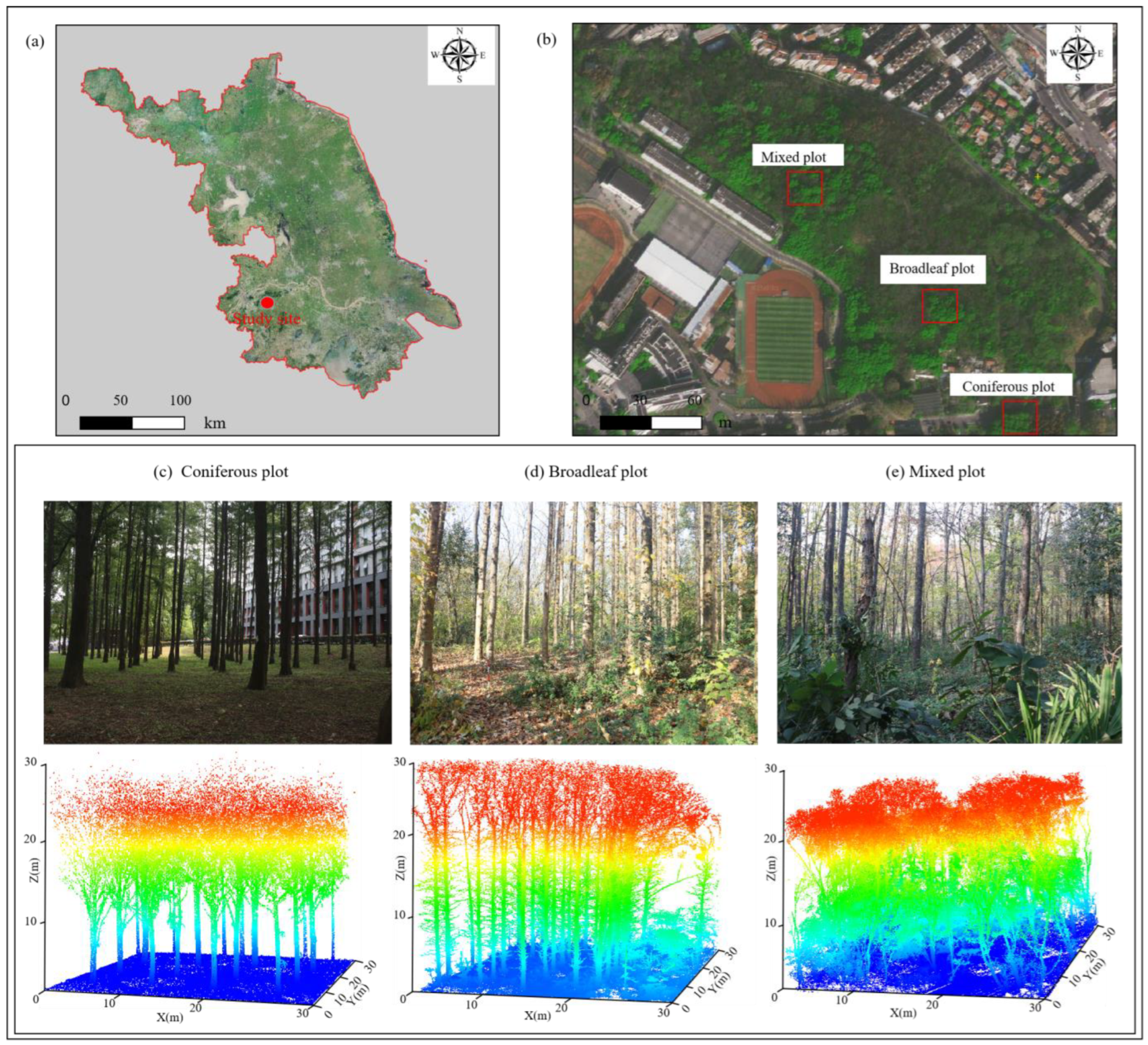
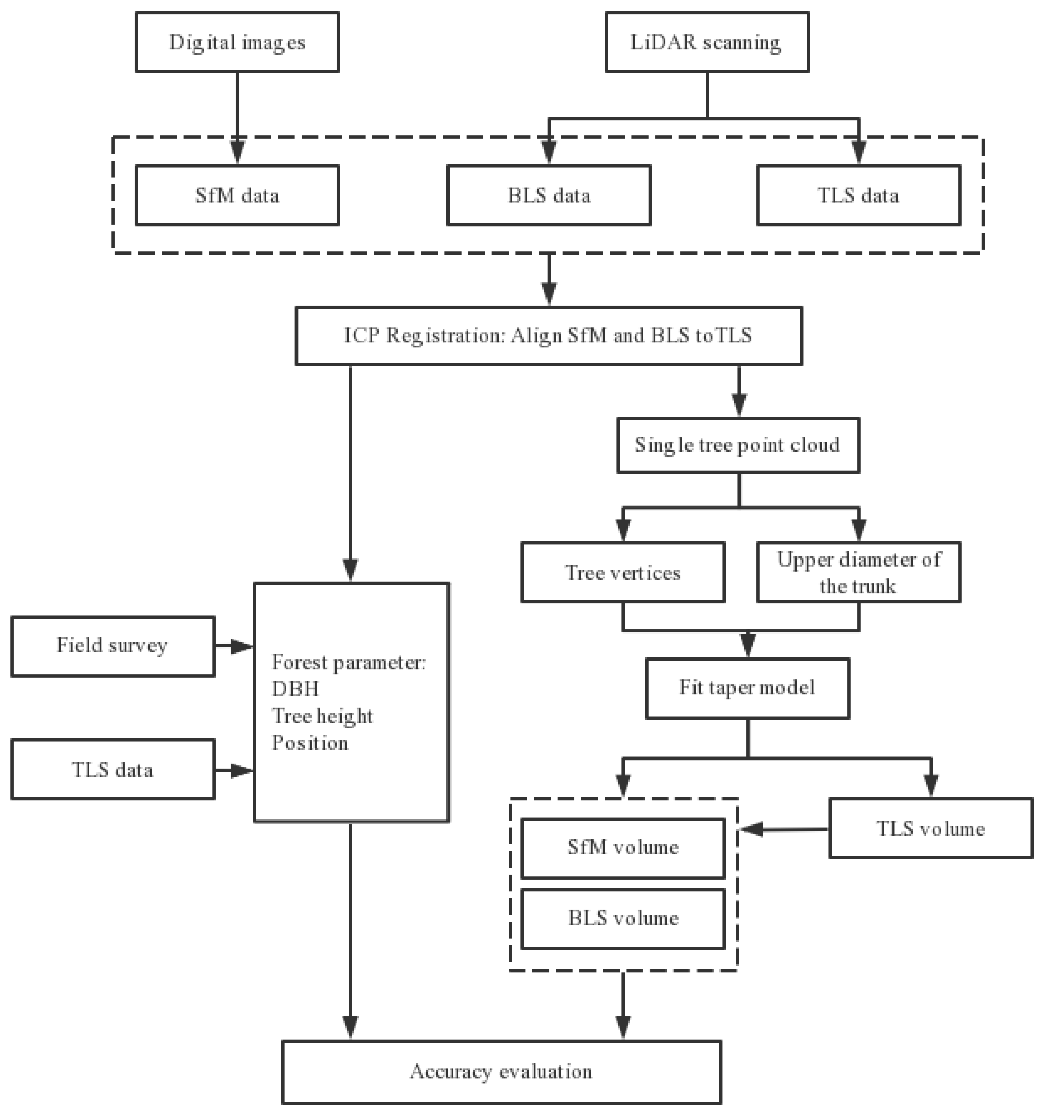
The research area was located in the Arboretum of Nanjing Forestry University, Jiangsu province (118°81′E, 32°01′N), with an elevation of approximately 20~30 m and a total area of approximately 252 ha. The climate was a subtropical humid monsoon climate, with an annual temperature difference of about 20 °C and an average annual precipitation of approximately 1106 mm. The dominant tree species include Taxodium distichum, Liriodendron chinensis, Masson pine, Ulmus pumila, etc. In this study, considering the status of visibility situation, understory vegetation and stand density information, the 3 sample plots (30 m × 30 m), including 1 coniferous plot, 1 broadleaf plot and 1 mixed plot (Figure 1), were divided into 3 categories, respectively: simple, medium and complex. The plant density of simple plot was generally lower than 600/ha, and the understory vegetation was sparse and the visibility was the best. The plant density of medium samples was approximately 1000/ha, and the understory vegetation was medium, the visibility was relatively better. The plant density of the mixed plot was high approximately 2000/ha and the understory vegetation was dense, the visibility was the worst. The technical route of the study is presented in Figure 2.
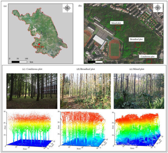
Figure 1.
(a) The location of the study site in Jiangsu province. (b) Rhe location of the three plots in the study site. (c–e) Plot photos and the 3D display of the TLS point clouds.
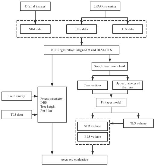
Figure 2.
Technical route describing the data collection, processing and analysis used for SfM, BLS and TLS. Acronyms: SfM, Structure from Motion; BLS, Backpack Laser Scanning; TLS, Terrestrial Laser Scanning; ICP, Iterative Closest Point.
2.2. Data Acquisition
2.2.1. Field Survey
The field survey was conducted from 5 November to 14 November 2021, and mainly investigated the tree structural information (location, DBH, tree height, crown width, etc.) of the plot. The 4 corners and the center position of the plot were obtained by teal-time kinematic (RTK), and the accuracy was higher than 0.5 m [44]. The direction and slope of the plot were measured by a compass instrument. In each plot, the species, spatial position (X and Y coordinates: by calculating its distance and horizontal angle relative to the center of the plot) with the DBH of ≥5 cm were recorded, and structural parameters such as DBH, tree height and crown width were measured. The DBH was measured using a diameter tap, and the tree height was obtained by Vertex IV ultrasonic altimeter. The structural parameters of the four main tree species in the three forest types were summarized in Table 1.

Table 1.
Summary of the structural parameters of individual trees in three sample plots.
2.2.2. LiDAR Data
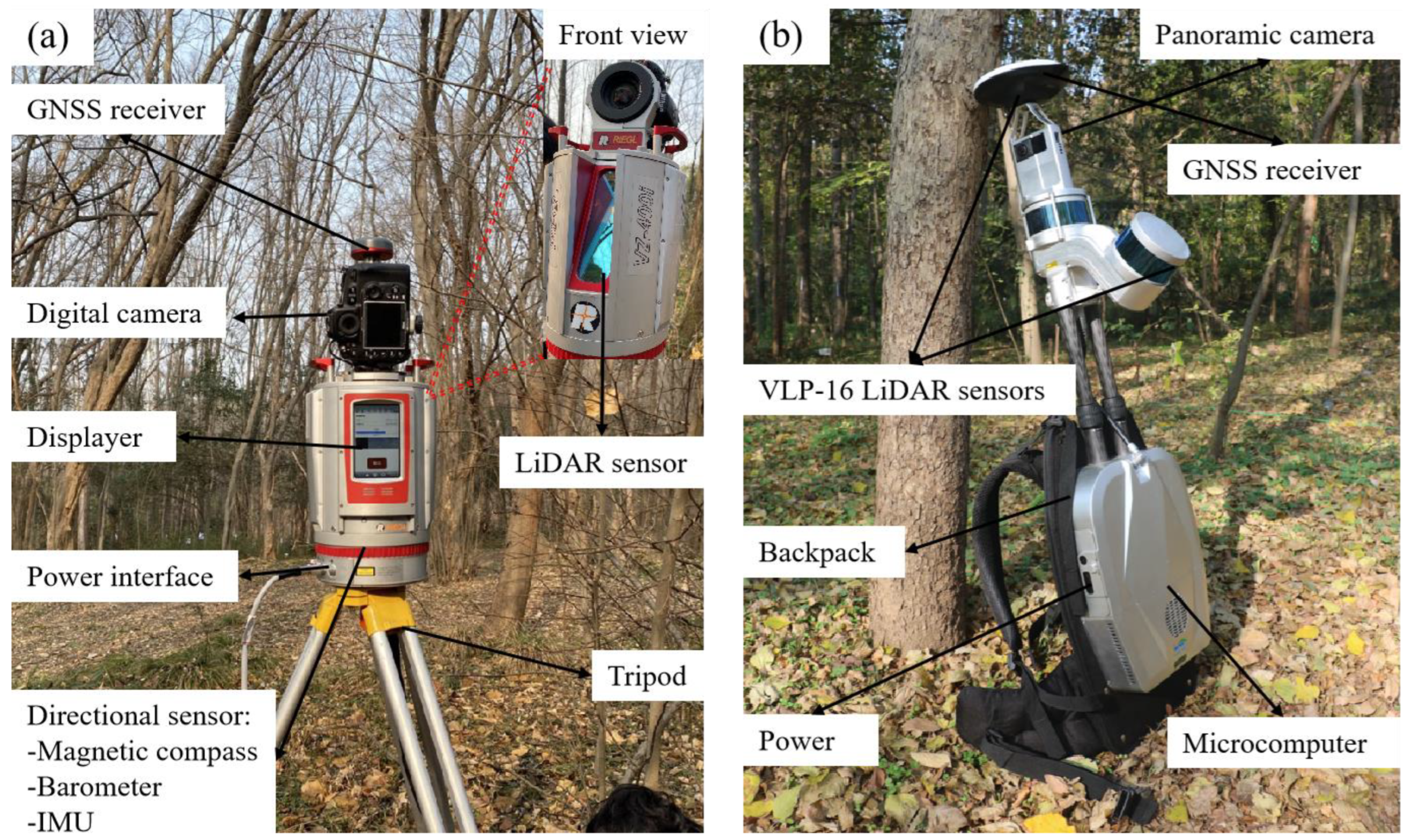
The TLS data were acquired by RIGEL VZ-400i terrestrial laser scanner (Figure 3). The point clouds were acquired by multi-station scanning with a scanning angle resolution was 0.08° and a multi-station stitching accuracy was 5 mm (Table 2). The scanning was completed in November 2021, and each plot was scanned using “#” style with 12 stations (4 stations are set up near the center of the plot, and 8 stations are set up at each edge of the plot, and the scanning sequence is shown in the discussion. Prior to scanning, the reflectance targets were wrapped around the tree trunk at the height of the breast. The targets were made of PVC material with a special coating on the surface, which can be recognized by the terrestrial 3D laser scanner. When scanning worked, the weather was sunny and breezy [45]. The scanned data were preprocessed such as stitching, denoising, normalization, and individual tree segmentation to obtain the point cloud data of each scanning project.
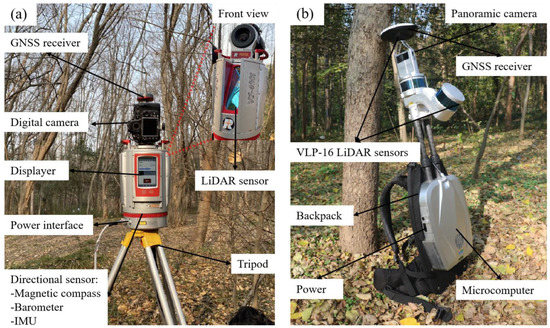
Figure 3.
LiDAR equipment. (a) Terrestrial laser scanning; digital camera collected true color photos to help generate colored point clouds, directional sensors such as extracted LiDAR, IMU, magnetic compass and barometer are responsible for collected laser data to generate point clouds; GNSS was used to receive satellite signals. (b) Backpack laser scanning; two VLP LiDAR sensors are responsible for collected laser data, and a panoramic camera recorded conditions during acquisition and generating color point clouds.

Table 2.
Comparison of TLS and BLS parameters.
The BLS data were acquired using a LiBackpack DGC50 device (GreenValley Technology Co., Ltd. (Beijing, China)), which had LiDAR sensors in both horizontal and vertical directions (Figure 3). The point cloud was collected on 15 November 2021, and the route used in the study was high overlap route. In order to facilitate the orientation in the more complex forest, a white target ball was erected at each of the four corners of the plot. LiBackpack DGC50 integrates SLAM algorithm (Simultaneous Localization and Mapping), and point cloud data can be obtained directly after field data collection.
2.2.3. Image Data Acquisition
The image data were shot with the Canon EOS 760D DSLR Camera, which had 24.2 million pixels and was equipped with an 18–135 mm zoom lens. The camera shooting parameters were set to: aperture F4.1, shutter speed 1/100 s and ISO fixed at 200. The study took three different photo acquisition routes and maintained an 80% overlap of every 2 adjacent consecutive photographs. Three photo acquisition routes were used in each plot. The first was “S” style, with the camera always due directly south and following the “S” shape from the corner point of the plot. The second was the “Circle” style, first walked along the “large circle” around the plot to shooting, and the camera direction was aimed at the center of the plot; after the “Big circle” shooting was completed, walked along the “Small circle” inside the plot, and the camera shoots radially from the circle outward. The third was a “Spiral Line” style, which took a larger circle along the edge of the plot, always aiming the camera at the center of the plot and gradually shrinking the circle around the plot from the outside to the inside.
SfM identified the feature points of trees from the captured images, determines the feature points of different images, obtained the 3D position of the point and the camera position corresponding to the images. First, binary descriptors in Hamming space are used to match images that correspond between key points (detected common features). Then, the matched key points and the images position and orientation recorded in the UAS were used for beam-method block adjustment to calculate the camera’s precise exterior orientation parameters for each image. Finally, according to the internal and external parameters of the camera and the coordinates of the 3D control point measured on site, the 3D coordinates matching the key points were calculated [46,47].
2.3. Point Cloud Data Registration
First, coarse registration is conducted, i.e., roughly matching the two sets of data into a coordinate system in preparation for fine registration. Using the reference data (TLS) and the registered data to calculate the coordinate transformation matrix between the two data by selecting control points (where the same position in the two sets of data), and making the coordinate correction of the data. When more than three pairs of selected points, the corresponding transformation matrix is generated and coarse registration is completed.
Then, registering the reference point cloud and the point cloud, the ICP (Iterative Closest Points) algorithm is used [48]. Assuming the two 3D point sets X1 and X2, the registration steps of the ICP method are as follows:
- Each point in X2 is the corresponding close point in X1;
- The rigid body transformation that minimize the average distance of the above corresponding points, and obtains the translation and rotation parameters;
- Use the translation and rotation parameters obtained in the previous step for X2 to obtain a new set of transformation points;
- If the average distance between the new transformed point set and the reference point set is less than a given threshold, the iterative calculation is stopped, otherwise the new set of transformed point is iterated as the new X2 until the requirement of the objective function is reached. In this study, BLS and SfM point clouds were coarsely registered by rotational translation matrices based on TLS point cloud data [19]. Point cloud rotation, translation and zoom factors were calculated by randomly selected 20 control points in TLS, BLS and SfM point clouds [21]. After coarse registration, they are fine registered using the ICP algorithm.
2.4. Individual Tree Segmentation
In this study, the density-based spatial clustering of applications with noise (DBSCAN) algorithm was used for the identification and segmentation of individual tree trunks, and the comparative shortest-path algorithm (CSP) was used to segment the canopy [48]. The DBSCAN algorithm used the minimum number of clustering points (MinPts) and radius of neighborhood (Eps) parameters to achieve clustering without the number of classes. When the trunk was detected, the point cloud with a height of 1.2~1.4 m was used as the input data, MinPts was set to 100, and the Eps (usually between 0.1 and 0.3 m) was adjusted according to the sample plots situation; after that, the cloud computing center of gravity of the trunk point at a height of 1.2~1.4 m was extracted, and the average distance from the center of gravity to each point of the trunk was the trunk radius, so as to calculate the DBH value. By combining algorithms that split individual trunks and crowns from point clouds, trunks can be successfully segmented without missing crown details. After the point cloud data was divided into single trees, the point cloud will be classified into different single trees, the point clouds in the same single tree will have the same ID information, and the highest point of each single tree point cloud collection will be regarded as the apex of the tree (the highest point of the single tree was also regarded as the tree vertex in field measurement). The average distance from the apex of all point clouds that are split into the same single tree was used as the crown radius of the tree. With the apex of the tree as the center of the circle, the relative vertical height value of the points where the center of the circle was located from the ground was the tree height information of the individual tree [49].
2.5. Trunk Taper Model Construction and Single Timber Volume Calculation
The Taper equation represented the equation in which the diameter of the trunk changes with height. The Taper equation can well describe the change trend of trunk shape, and had also become the basic method for studying the amount of wood produced by trees. After the Taper model was evaluated, the best Taper equation was integrated and the corresponding volume equation was obtained. Four Taper equations were selected as alternative models in the equations shown in (2)–(5). In order to unify the form of the Taper equation and facilitate the calculation of the individual tree product, Taper equation form was uniformly converted. The specific form is:
Using the extracted tree height, DBH and trunk diameter (trunk diameter above 1.3 m) and other structural parameters fitted with the following five alternative Taper equations. By comparing the fitted error and accuracy, the most accurate Taper equation model was selected to use.
where D was the chest diameter, H was the tree height, h was the height of the trunk somewhere, and d was the diameter of the trunk from the ground height, h, a0, a1, a2, and a3 represent the parameters.
After the evaluation of five Taper models, the optimal Taper model of different equipment of each tree species is selected, and the parameters obtained by regression analysis are substituted into the optimal trunk Taper model, and the corresponding volumetric model is obtained by integrating them, and the integral expression of the model is as follows:
where V represented Volume, K = π/40,000 (fixed integral and unit conversion coefficient), f (h, H, D) is a function of the diameter at different heights of the trunk. Using the general expression of the standing timber volume model obtained by two tree species, enter the two variables of tree height and DBH, and calculate the corresponding standing timber volume.
2.6. Accuracy Evaluation
The accuracy evaluation of individual tree segmentation was based on the existence of real trees within the canopy width of the detected tree vertex, and the detection of real tree points within the radius of the canopy was considered to be accurate [47]. The three indicators reflecting the effect of individual tree segmentation were detection rate (r), correct detection rate (p) and overall accuracy (F). After the individual tree segmentation, the following three indicators were used to evaluate the accuracy of the individual tree segmentation:
where r represented the tree detection rate, p represented the tree detection accuracy and F represented the overall accuracy taking both omission and accurate detection into consideration. The higher the number, the more accurate it is. Nt was the number of tree tops detected and presented on the plot, Nc was the number of tree tops detected but not actually presented and No was the number of tree tops that were not detected but actually existed—and additionally, the corresponding calculation of three evaluation indicators.
The coefficient of determination (R2), root mean square error (RMSE) and relative root mean square error (rRMSE) were used to evaluate the extracted parameters such as DBH, tree height and volume, and the formulas were:
where represented observed forest structural attributes for the i tree; is the estimated forest structural attributes for the i tree; n represented the number of trees; and was the observed mean value.
3. Results and Analysis
3.1. Individual Tree Segmentation
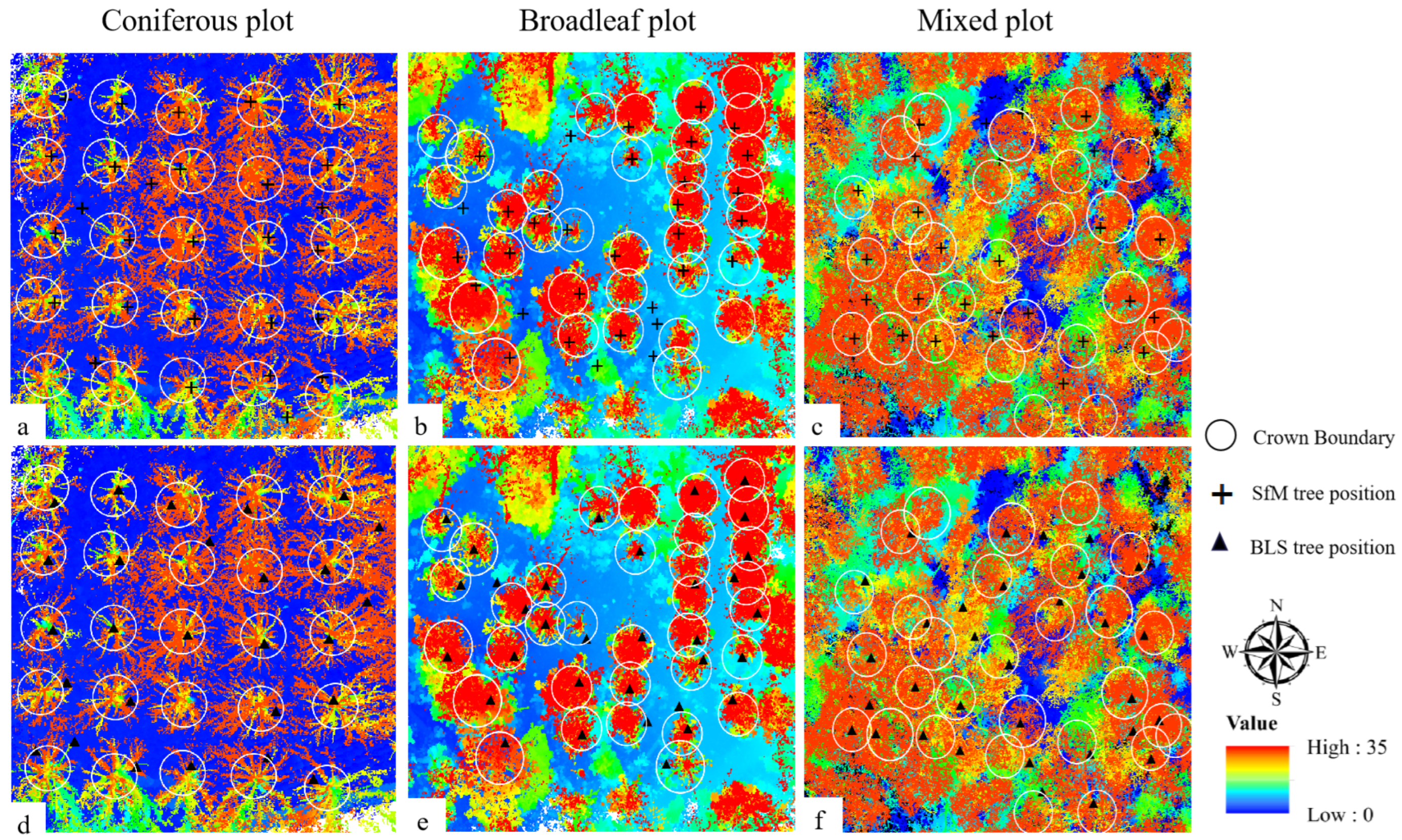
The individual tree segmentation based on the CSP algorithm performed well (SfM average F = 0.80, BLS average F = 0.85). Figure 4 is a tree position map of SfM and BLS after individual tree segmentation, where the white circle is the position measured by TLS, the cross-filament mark is the position measured by SfM and the triangle mark is the position measured by BLS—that is, when the mark falls within the white circle, recorded as Nt, when there is no mark in the white circle, recorded as No, and when the mark is present alone, recorded as Nc. Table 3 is calculated according to Formulas (7)–(9). The SfM point cloud had the highest overall accuracy in the Coniferous plot (F = 0.87) and the lowest overall accuracy in the Mixed plot (F = 0.75). The BLS point cloud had the highest overall accuracy in Broadleaf plot (F = 0.93) and the lowest overall accuracy in Mixed plot (F = 0.77). The forest stands of mixed forests were complex, and there were many tall shrubs and fallen trees, which were easy to affect the segmentation accuracy. Compared with BLS, the accuracy of SfM was lower than that of BLS.
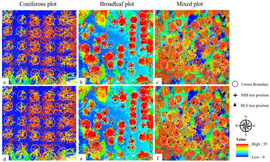
Figure 4.
SfM and BLS individual tree segmentation results in the three sites (30 × 30 m2) (The crown boundary represents the position of the tree that is actually measured). (a–c) Individual Tree Segmentation of the SfM data; (d–f) Individual Tree Segmentation of the BLS data.

Table 3.
The accuracy assessments for the individual tree segmentation algorithms of BLS and SfM.
3.2. Analysis of DBH and Tree Height Extraction
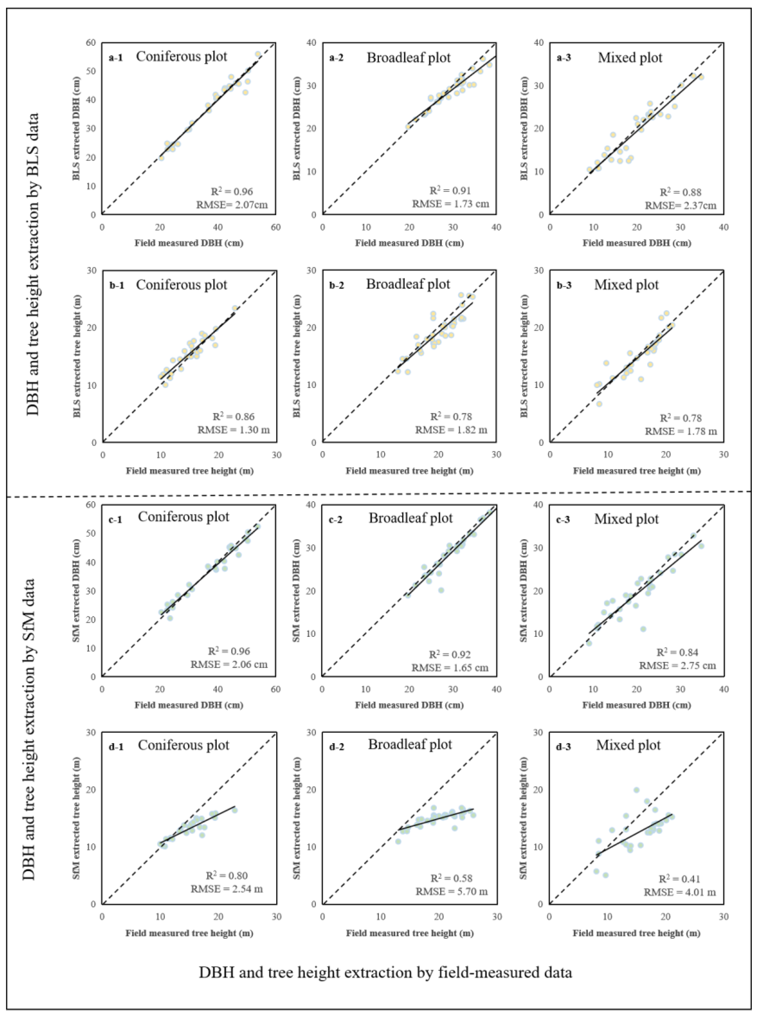
In the comparison with the field-measured data, the DBH accuracy extracted by BLS and SfM were high (BLS R2 = 0.92, SfM R2 = 0.91). In the Coniferous plot, the R2 of DBH extraction of BLS and SfM point clouds were 0.96, and RMSE were 2.07 cm and 2.06 cm. In Broadleaf plot, DBH extraction of SfM were better than BLS, with R2 = 0.92, RMSE = 1.65 cm. In Mixed plot, DBH extraction of BLS were better than SfM with R2 = 0.88 and RMSE = 2.37 cm. In the comparison with the field-measured data (Table 4), the average accuracy of the tree height extracted by BLS was higher than the SfM data (BLS R2 = 0.81, SfM R2 = 0.60). In Coniferous plot, Broadleaf plot and Mixed plot, the R2 and RMSE of tree heights extracted by BLS were higher than that extracted by SfM data (Figure 5). BLS data were best in Coniferous plot with R2 = 0.86, RMSE = 1.30 m.

Table 4.
Accuracy assessment of DBH and tree height extraction between using BLS, SfM data and using field-measured data.
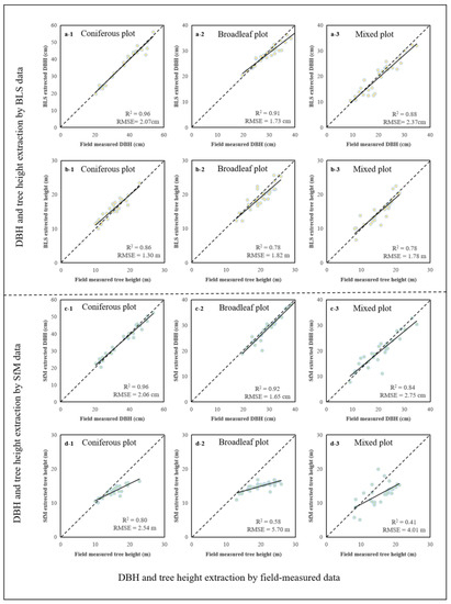
Figure 5.
Scatter plots of the DBH and tree height comparison between using BLS, SfM data and using the field-measured data. (a-1–a-3) validation results of BLS data extracted the DBH; (b-1–b-3) validation results of BLS data extracted the tree height; (c-1–c-3) validation results of SfM data extracted the DBH; and (d-1–d-3) validation results of SfM data extracted the tree height.
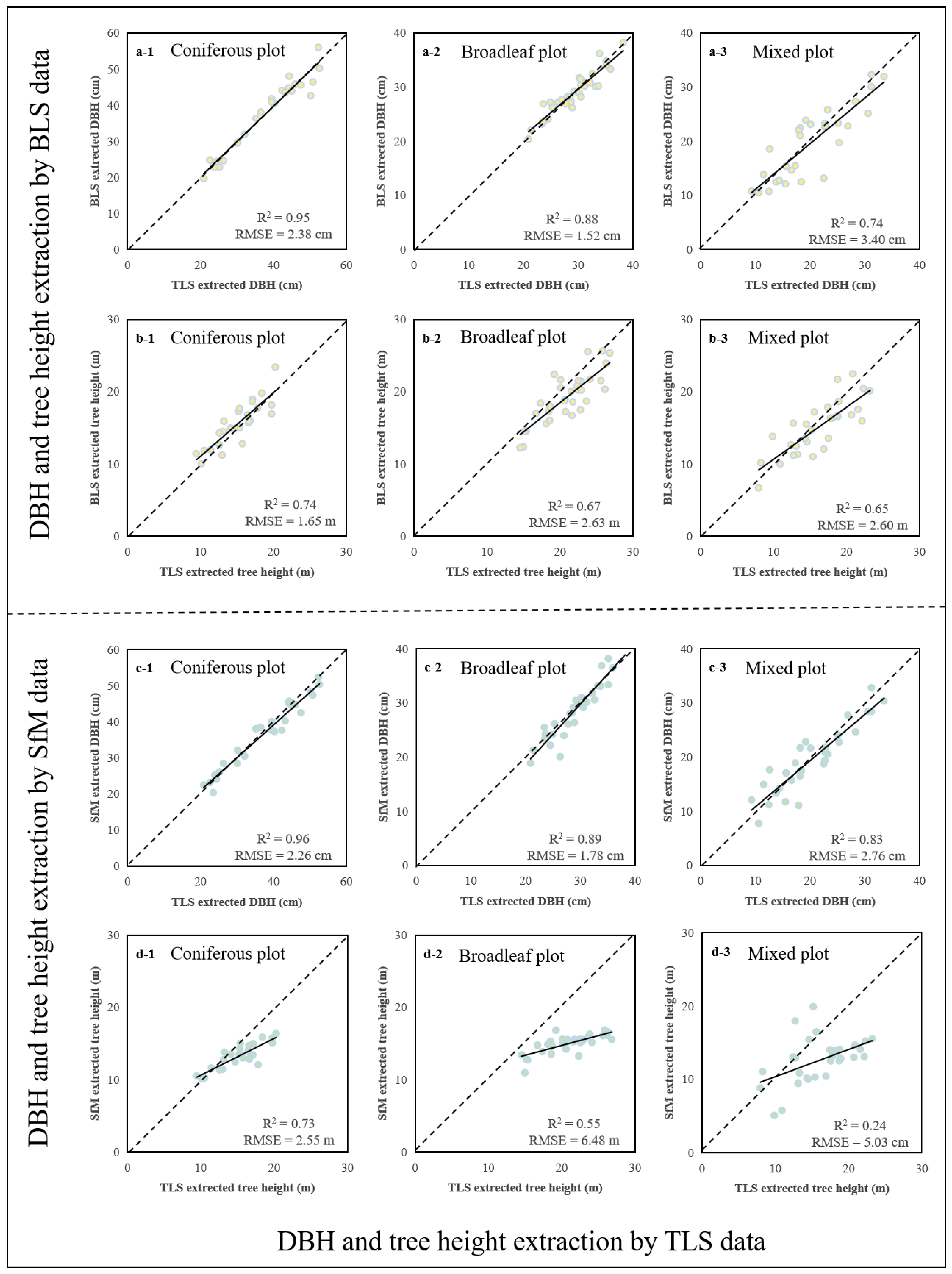
Figure 6 is the scatter plot of tree parameters (DBH, tree height) by TLS and tree parameters by BLS and SfM. In the comparison with the TLS data, the DBH accuracy extracted by BLS and SfM were high (BLS R2 = 0.95, SfM R2 = 0.96) (Table 5). The R2 and RMSE of DBH extracted by SfM were higher than that extracted by BLS data. SfM data was best in Coniferous plot with R2 = 0.96. In the Coniferous plot, Broadleaf plot, and Mixed plot, the R2 and RMSE of tree heights extracted by BLS were higher than that extracted by SfM data. BLS data was best in Coniferous plot with R2 = 0.74, RMSE = 1.65 cm.
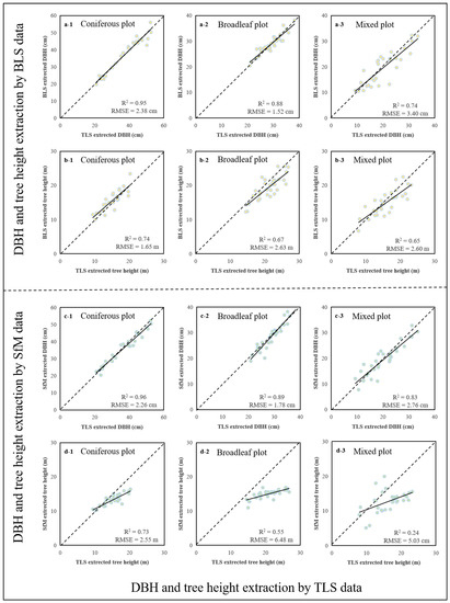
Figure 6.
Scatter plots of the DBH and tree height comparison between using BLS, SfM data and using TLS data. (a-1–a-3) validation results of BLS data extracted the DBH; (b-1–b-3) validation results of BLS data extracted the tree height; (c-1–c-3) validation results of SfM data extracted the DBH; and (d-1–d-3) validation results of SfM data extracted the tree height.

Table 5.
Accuracy assessment of DBH and tree height extraction between using BLS, SfM data and using TLS data.
3.3. Trunk Taper Model Construction and Volume Extraction Analysis
3.3.1. Taper Model Construction
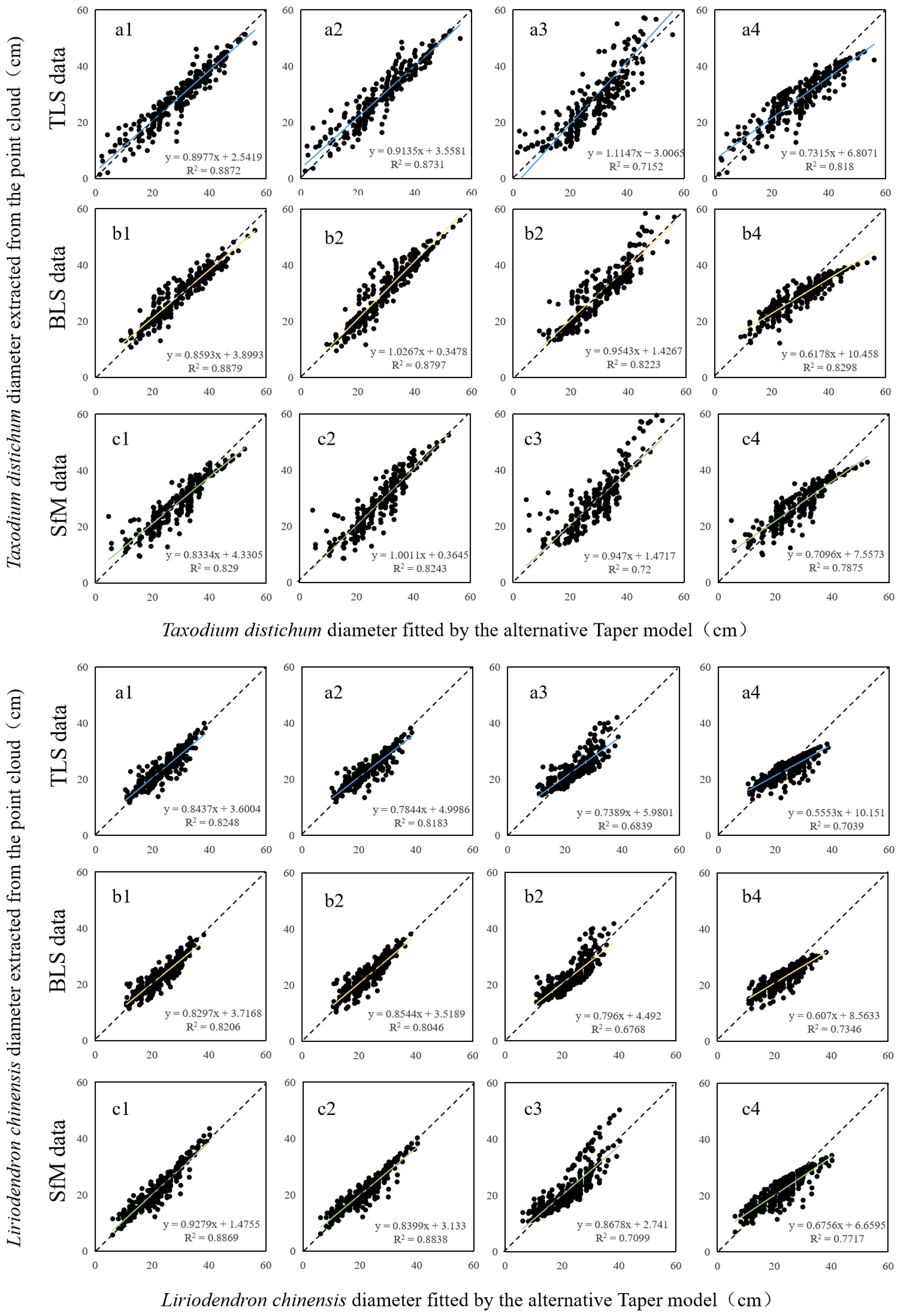
In Figure 7, the 1–4 represent the 4 alternative Taper equations, where the model 4 has a low slope and has a large deviation compared with model 1–3, with Taxodium distichum average rRMSE = 14.14% and Liriodendron chinensis average RMSE = 11.48%, not suitable for these 2 tree species. Model 3 has the lowest accuracy, with Taxodium distichum average R2 = 0.75 and Liriodendron chinensis average R2 = 0.69. In the other 2 equations, the model 1 (improved Schumacher Taper model) had the highest accuracy. The diameter of the Taxodium distichum fitted by the TLS data (Table 6), R2 = 0.89, RMSE = 3.97 cm, rRMSE = 13.82%, the diameter of the Taxodium distichum fitted by the BLS data: R2 = 0.89, RMSE = 3.11 cm, rRMSE = 10.58%, the diameter of the Taxodium distichum by SfM data, R2 = 0.83, RMSE = 3.66 cm, rRMSE = 12.96%. The diameter of the Liriodendron chinensis fitted by the TLS data (Table 7): R2 = 0.82, RMSE = 2.41 cm, rRMSE = 8.52%, the diameter of the Liriodendron chinensis fitted by the BLS data: R2 = 0.82, RMSE = 2.34 cm, rRMSE = 8.3%, the diameter of the Liriodendron chinensis fitted by SfM data: R2 = 0.89, RMSE = 2.36 cm, rRMSE = 8.34%. Therefore, the model 1 is chosen as the volume calculation equation.
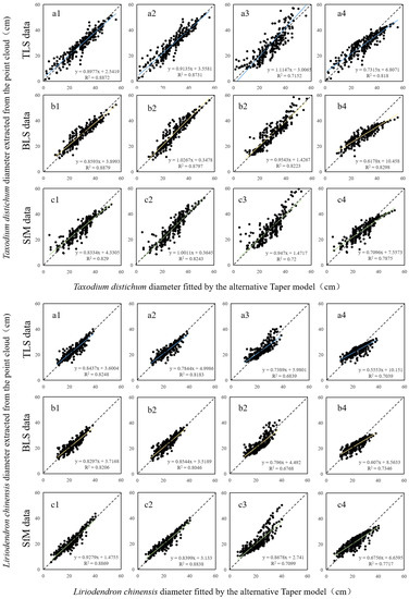
Figure 7.
Scatter plots of the diameter fitted by the alternative Taper model and the diameter extracted from the point cloud ((a) represents TLS data, (b) represents BLS data, (c) represents SfM data; the numbers 1–4 represents model numbers).

Table 6.
Accuracy assessment of the 1–4 model in Taxodium distichum.

Table 7.
Accuracy assessment of the 1–4 model in Liriodendron chinensisr.
3.3.2. Establishment of Optimal Taper Model
The improved Schumacher Taper model was compared to the best fit of the Taper equation, and the parameters obtained by the Levenberg–Marquardt iterative regression analysis were substituted into the formula. A total of 6 optimal Taper models were obtained:
Taxodium distichum TLS data optimal Taper model:
Taxodium distichum BLS data optimal Taper model:
Taxodium distichum SfM data optimal Taper model:
Liriodendron chinensis TLS data optimal Taper model:
Liriodendron chinensis BLS data optimal Taper model:
Liriodendron chinensis SfM data optimal Taper model:
where d represents the diameter, h represents the corresponding height of the diameter, H represents the height of a single tree and D represents the DBH of a single plant.
3.3.3. Volumetric Model Evaluation
By substituting the parameters of each optimal Taper model into the general form of the volumetric model, the binary Taper volumetric model expression of TLS, BLS and SfM was obtained:
Taxodium distichum TLS data binary Taper volumetric model:
Taxodium distichum BLS data binary Taper volumetric model:
Taxodium distichum SfM data binary Taper volumetric model:
Liriodendron chinensis TLS data binary Taper volumetric model:
Liriodendron chinensis BLS data binary Taper volumetric model:
Liriodendron chinensis SfM data binary Taper volumetric model:
where K = π/40,000 (fixed integral and unit conversion coefficient), V represented Volume, D represented DBH and H represented tree height.
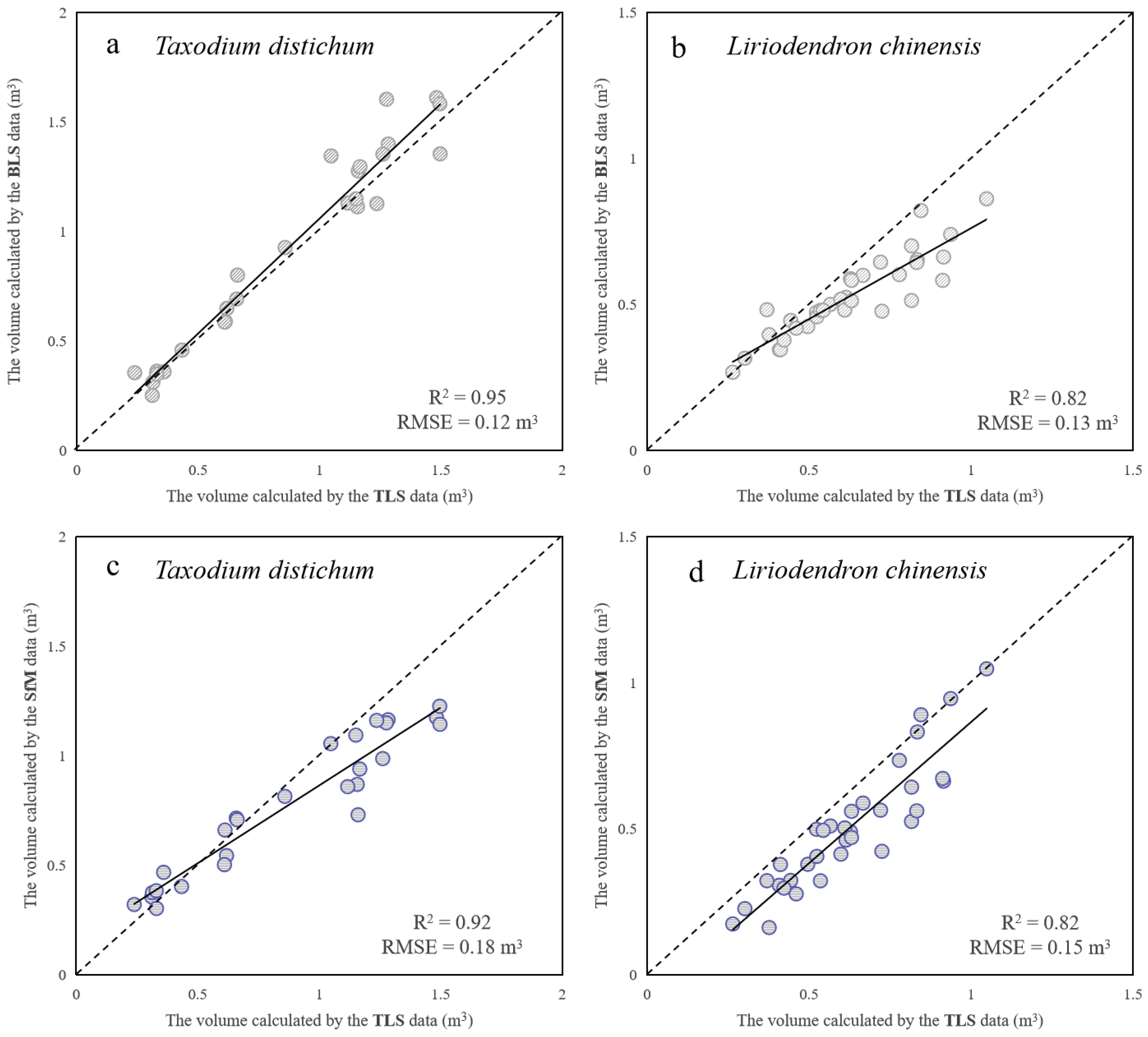
Based on the above binary Taper volume models, the tree height and DBH extraction by substituting each tree can obtain the volume of each tree. The TLS volume were taken as the true value, and the BLS and SfM volume was used as the estimated value, and the three indicators of R2, RMSE and rRMSE were also used for evaluation, as shown in Figure 8.
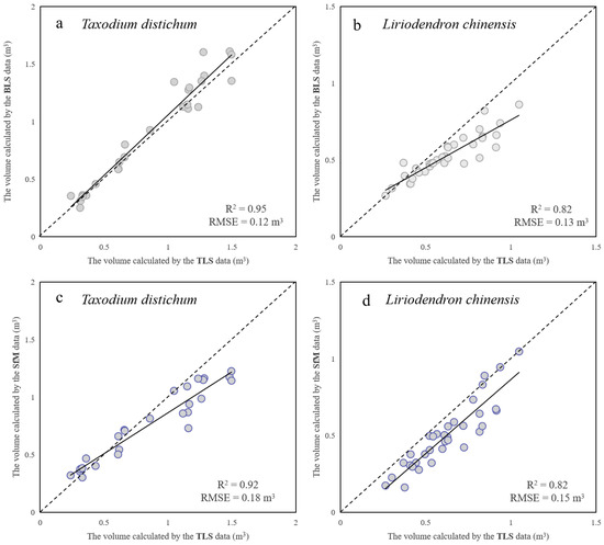
Figure 8.
Scatter plot of the volume calculate between using the TLS data and using BLS, SfM data. ((a) represents Taxodium distichum volume calculated by BLS data, (b) represents Liriodendron chinensis volume calculated by BLS data, (c) represents Taxodium distichum volume calculated by SfM data and (d) represents Liriodendron chinensis volume calculated by SfM data.)
The study estimated the volume of tree species, and the results were shown in Table 8. The R2 of the Taxodium distichum volume calculated by BLS was 0.95 and the RMSE was 0.12 m3, rRMSE was 12.6%. The R2 of the Taxodium distichum volume calculated by SfM was 0.92 and RMSE was 0.18 m3, rRMSE was 23.3%. The R2 of the Liriodendron chinensis volume calculated by BLS was 0.82 and RMSE was 0.13 m3, rRMSE was 25.67%. The R2 of the Liriodendron chinensis volume calculated by SfM was 0.82 and RMSE 0.15 m3, rRMSE was 30%. Among them, the volume R2 of SfM calculation, which has the worst effect, is also above 0.82, which showed that the devices had a good application in calculating volume.

Table 8.
Accuracy assessment of volume between using Taper model and TLS data.
4. Discussion
In this study, TLS was used as the benchmark, and moreover, highly overlapping images and BLS data taken on the ground by multiple methods were used, combined with SfM 3D point cloud reconstruction, point cloud matching, DBH and stem shape extraction. The accuracy and efficiency of low-cost SfM and portable BLS point clouds in forest structural parameter extraction were comparatively studied. Most of the previous studies on obtaining forest structural parameters through SfM and BLS were based on simple pure forest research areas, and the obtained forest structural parameters can reach a high level. Three study areas of different complexity were selected to explore the 3D reconstruction capabilities of SfM and BLS. TLS, SfM and BLS adopt a variety of different line acquisition methods, taking into account factors such as topography, efficiency and feasibility, and based on the best point cloud data selected by a variety of routes, the comparison and analysis was carried out [50,51,52,53].
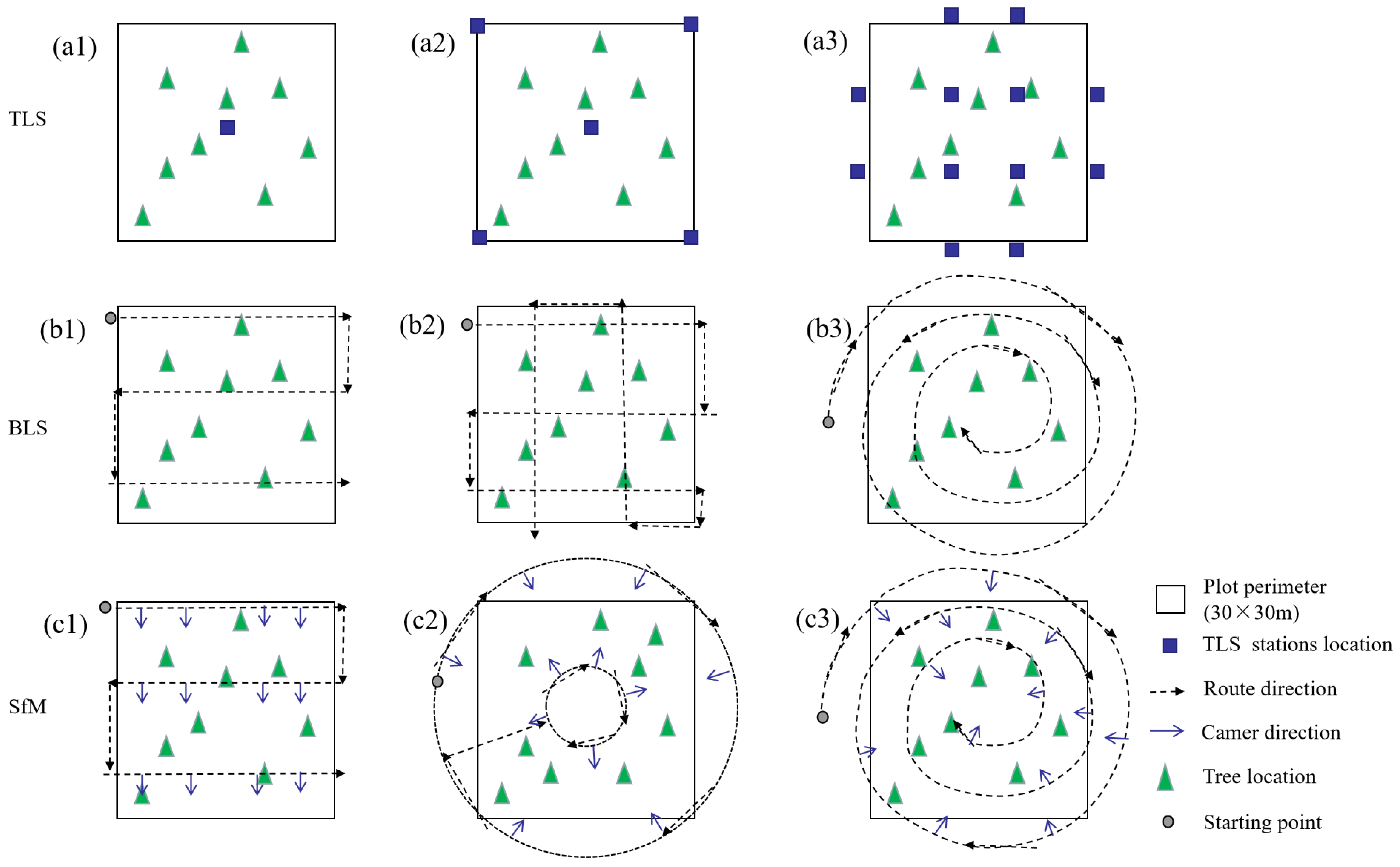
The data acquisition route used in the study had undergone many experiments, and finally, TLS adopt “#” style method, BLS adopt the High overlap route and SfM adopt the wrap-around route. Different TLS layout methods have an impact on the accuracy of point clouds, and according to different studies, a total of three different methods were laid out in coniferous plot. (1) Single-station method (Figure 9(a1)): that is, only the central set site was used for scanning, and it only takes about 20 min; (2) 5-station method (Figure 9(a2)): station scanning was carried out at the center and the 4 corner points of the plot. It took about 1 h; (3) “#” station method (Figure 9(a3)): 12 stations were laid in the coniferous plot for scanning. It took about 2 h 20 min. The results show that the first and second methods were not suitable for high-precision extraction of forest parameters such as breast diameter and tree height, and finally adopt the “#” layout method, and scan data in broadleaf and mixed plot. According to different studies, BLS used three ways in coniferous, broadleaf and mixed plots. (1) “S” style (Figure 9(b1)): followed the “S” shape from the corner point of the plot; (2) high overlap route (Figure 9(b2)): take the same route as when mapping UAV, and repeat once horizontally and vertically; (3) “Spiral Line” style (Figure 9(b3)): walked in circles at the edge of the plot and gradually shrink the circle around the plot. Finally, the BLS point cloud data used the High overlap route. The discussion of the SfM route was mentioned in the above method, and the study conducted several experiments on coniferous, broadleaf and mixed plot, and finally, agreed to select the data acquired by the “Spiral Line” style (Figure 9(c3)). The “S” style in the Figure 9(c1), the “Circle” style in the Figure 9(c2).Livia et al. [37] added “#” shooting route to the “circle” style, and ultimately, achieved good results. The route in the research was compared in the accuracy of the point cloud and the comparison in time efficiency. TLS took “#” station method, BLS took the High overlap route and SfM took the “Spiral Line” style. Su extracted the poplar’s forest structure parameters using a combined BLS and ULS (Unmanned Laser Scanning) manner. In comparison, we selected three plots with different densities for the study. Considering that the terrestrial photography cannot capture the top of the tree, in future research we will use UAV (unmanned aerial vehicle) to obtain forest images, and combine with SfM to calculate more accurate tree height information. We will use drone photos taken at different altitudes in the air, generate point clouds through SfM and merge with terrestrial photography to get a complete forest structure.
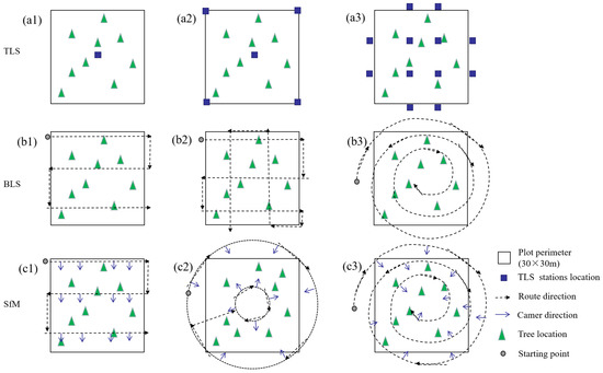
Figure 9.
TLS, BLS and SfM acquisition route. (a1–a3) TLS data acquisition route; (b1–b3) BLS data acquisition route; and (c1–c3) SfM acquisition route.
Coniferous, broadleaf and mixed plots with different understory vegetation and stand densities have a great influence on the accuracy and efficiency of forest structural parameter extraction. In coniferous plot, SfM and BLS have the characteristics of high precision and high efficiency because of the flat terrain, good visibility and few shrubs under the forest. SfM took a total of 45 min to plan the route and take photos, and about 400 photos with a high repetition rate were taken. The computer parameters used in the data processing were Intel(R)Core(TM)i7-10700 CPU@2.90 GHz, and the process of converting photos from the computer to point clouds took a total of 5 h and 42 min. BLS spend about 45 min collecting data, of which more time (20 min) was used to receive GPS signals before laser scanning and bypass closed curves. The point cloud was calculated by the integrated SLAM algorithm of the LiBackpack DGC50, and the data can be exported at the end of the experiment. TLS was used longer on assembly equipment, and it was also necessary to wrapped around the reflectance targets to the tree trunk in advance. Although the time of TLS single-station scanning was only about 5 min, in order to achieve a good stitching effect, you need to consider the location of each subsequent site. The total time for collecting TLS data in coniferous plot was about 1 h 20 min, and about 2 h and 30 min in data processing. In broadleaf plot, TLS took 1 h and 30 min, SfM took 35 min and BLS took 45 min. In mixed plot, TLS took a total of 2 h, SfM took 1 h 20 min and BLS took 50 min. The time calculation of SfM is the start time from the first photo taken by the videographer and the end time to the last photo. The time calculation of BLS starts from the injection site of the BLS operator and ends at the end of the route. The TLS requires two people to operate due to the weight of the machine and tripod. The time is calculated when the first site is scanned. Furthermore, the last site is scanned and the time is calculated at the end of the total time evenly divided into each person.
Due to the limitations of high cost and inefficiency of TLS, multiple scans were required to mitigate the forest shading effect, which affects its widespread used in forest resource surveys. Terrestrial SfM photogrammetry offers a potentially low-cost and fast solution due to the camera’s greater price advantage and portability over LiDAR equipment. In contrast to TLS data, images acquired by SfM were saved in a standard format and can be processed using vendor-independent processing software. As a result, there was greater flexibility in the choice of processing software (even open-source solutions) [54].
Mona presents a novel method to measure DBH and tree positions on field plots using a calibrated multi-camera rig [55]. The calibration information is used to improve the quality of the produced point cloud by reducing the number of false matches. Furthermore, the point cloud is automatically scaled without any additional measurements or targets in the scene. Compared to this method, we are less efficient with a single camera. Therefore, we intend to increase the efficiency of using two panoramic cameras to shoot by elevated.
The accuracy of SfM was much lower than that of BLS (ΔRMSE = 2.45 m) when extracting tree high parameters. Due to the angle of camera shooting, some SfM extracted tree vertices were not actual tree vertices, but part of the trunk, so SfM lags far behind BLS in tree height extraction. However, in the more practical application of volumetric estimation in forestry surveys, SfM can be calculated by the same effective Taper equation as the BLS. BLS had great advantages over TLS and SfM in tree height extraction. First of all, the point cloud accuracy of BLS was high enough to be used as precision forestry research; and secondly, the cost of use was much lower than TLS, and it had the same portability as SfM. The BLS had a scanning angle range of 180° vertical and 360° horizontal, which exceeds TLS (vertical 100°) in vertical viewing angle field, and had the advantage of scanning tall trees. The accuracy of the BLS in coniferous and broadleaf measurements of DBH was lower than that of SfM, possibly because of errors due to point cloud density. BLS point cloud data with its extremely high point density, the detailed structural information of the surface layer of the trunk can be obtained (for example, bark thickness can be reflected in the point cloud data by high-density point cloud), so it was possible to extract the diameter of the tree with or without bark. We discuss the feasibility of TLS, SfM and BLS taking other routes, comparing the prices between them and the time taken to collect the data. It is concluded that SfM using “Spiral Line” style is the optimal solution. Without considering the price, BLS collects data with fast time and high accuracy.
5. Conclusions
In this study, the terrestrial high-overlapped images which were taken in multiple ways and the BLS point cloud—combined with the SfM point cloud reconstruction, point cloud co-registration, diameter at breast height extraction and tree trunk simulation—to extract the forest structural parameters and compared with the TLS for assessing the accuracy and efficiency of low-cost SfM and portable BLS point clouds. The following conclusions were drawn: (1) The accuracy of DBH and tree height extraction based on the SfM and BLS point clouds comparison with the field-measured data were relatively high. The average RMSE of DBH and tree height extraction based on SfM point cloud were 2.15 cm and 4.08 m, and the average RMSE of DBH and tree height extraction based on BLS point cloud were 2.06 cm and 1.63 m. (2) The DBH extracted from SfM point cloud was closed to that from TLS point cloud (RMSE = 2.27 cm), and the tree height extraction from BLS was closed to that from TLS point cloud (RMSE = 2.29 m). (3) BLS calculation Taxodium distichum taper volume with R2 = 0.95, RMSE = 0.12 m3 and Liriodendron chinensis with R2 = 0.82, RMSE = 0.14 m3. SfM calculation Taxodium distichum taper volume with R2 = 0.92, RMSE = 0.18 m3 and Liriodendron chinensis with R2 = 0.82, RMSE = 0.15 m3. (4) The individual tree segmentation based on SfM and BLS point clouds all performed well, among which the segmentation accuracy (F) of SfM point cloud was 0.80 and the BLS point cloud was 0.85. The results showed that the performance of SfM point cloud in extracting DBH and volume are very close to the BLS and TLS data, which can be applied to forestry surveys.
Author Contributions
Conceptualization, L.C.; methodology, Z.X. and X.S.; software, Z.X.; validation, Z.X. and X.S.; formal analysis, Z.X.; writing—original draft preparation, Z.X.; writing—review and editing, Z.X., X.S. and L.C.; visualization, Z.X.; supervision, L.C.; funding acquisition, L.C. All authors have read and agreed to the published version of the manuscript.
Funding
This research was funded by the National Key Research and Development Program (2022YFD2200101) and the Priority Academic Program Development of Jiangsu Higher Education Institutions (PAPD).
Conflicts of Interest
The authors declare no conflict of interest.
References
- Kankare, V.; Joensuu, M.; Vauhkonen, J.; Holopainen, M.; Tanhuanpä, T.; Vastaranta, M.; Hyyppä, J.; Hyyppä, H.; Alho, P.; Rikala, J. Estimation of the timber quality of Scots pine with terrestrial laser scanning. Forests 2014, 5, 1879–1895. [Google Scholar] [CrossRef]
- Wallace, L.; Lucieer, A.; Malenovský, Z.; Turner, D.; Vopěnka, P. Assessment of forest structure using two UAV techniques: A comparison of airborne laser scanning and structure from motion (SfM) point clouds. Forests 2016, 7, 62. [Google Scholar] [CrossRef]
- Liang, X.; Jaakkola, A.; Wang, Y.; Hyyppä, J.; Honkavaara, E.; Liu, J.; Kaartinen, H. The use of a hand-held camera for individual tree 3D mapping in forest sample plots. Remote Sens. 2014, 6, 6587–6603. [Google Scholar] [CrossRef]
- Newnham, G.J.; Armston, J.D.; Calders, K.; Disney, M.I.; Lovell, J.L.; Schaaf, C.B.; Strahler, A.H.; Danson, F.M. Terrestrial laser scanning for plot-scale forest measurement. Curr. For. Rep. 2015, 1, 239–251. [Google Scholar] [CrossRef]
- Liang, X.; Kukko, A.; Hyyppä, J.; Lehtomäki, M.; Pyörälä, J.; Yu, X.; Kaartinen, H.; Jaakkola, A.; Wang, Y. In-situ measurements from mobile platforms: An emerging approach to address the old challenges associated with forest inventories. ISPRS J. Photogramm. Remote Sens. 2018, 143, 97–107. [Google Scholar] [CrossRef]
- Hawley, C.M.; Loudermilk, E.L.; Rowell, E.M.; Pokswinski, S. A novel approach to fuel biomass sampling for 3D fuel characterization. MethodsX 2018, 5, 1597–1604. [Google Scholar] [CrossRef]
- Lisein, J.; Pierrot-Deseilligny, M.; Bonnet, S.; Lejeune, P. A Photogrammetric Workflow for the Creation of a Forest Canopy Height Model from Small Unmanned Aerial System Imagery. Forests 2013, 4, 922–944. [Google Scholar] [CrossRef]
- Wang, D.; Hollaus, M.; Puttonen, E.; Pfeifer, N. Automatic and self-adaptive stem reconstruction in landslide-affffected forests. Remote Sens. 2016, 8, 974. [Google Scholar] [CrossRef]
- Iglhaut, J.; Cabo, C.; Puliti, S. Structure from motion photogrammetry in forestry: A review. Curr. For. Rep. 2019, 5, 155–168. [Google Scholar] [CrossRef]
- Fang, R.; Strimbu, B.M. Stem measurements and taper modeling using photogrammetric point clouds. Remote Sens. 2017, 9, 716. [Google Scholar] [CrossRef]
- Giannetti, F.; Chirici, G.; Gobakken, T.; Næsset, E.; Travaglini, D.; Puliti, S. A new approach with DTM-independent metrics for forest growing stock prediction using UAV photogrammetric data. Remote Sens. 2018, 213, 195–205. [Google Scholar] [CrossRef]
- Liang, X.; Kukko, A.; Kaartinen, H.; Hyyppä, J.; Yu, X.; Jaakkola, A.; Wang, Y. Possibilities of a Personal Laser Scanning System for Forest Mapping and Ecosystem Services. Sensors 2014, 14, 1228–1248. [Google Scholar] [CrossRef] [PubMed]
- Qianli, L.; Chunyou, L.; Ping, M. Tree measurement method and data analysis of multi-baseline digital close-up photogrammetry system. For. Sci. 2010, 46, 166–170. [Google Scholar]
- Xiumei, W.; Zhuoqiao, Z. Application of digital photogrammetry technology in forest survey. For. Resour. Manag. 2001, 1, 31–35. [Google Scholar] [CrossRef]
- Smith, A.; Astrup, R.; Raumonen, P.; Liski, J.; Krooks, A.; Kaasalainen, S.; Åkerblom, M.; Kaasalainen, M. Tree root system characterization and volume estimation by terrestrial laser scanning and quantitative structure modeling. Forests 2014, 5, 3274–3294. [Google Scholar] [CrossRef]
- Liang, X.; Wang, Y.; Jaakkola, A.; Kukko, A.; Kaartinen, H.; Hyyppä, J.; Honkavaara, E.; Liu, J. Forest data collection using terrestrial image-based point clouds from a handheld camera compared to terrestrial and personal laser scanning. IEEE Trans. Geosci. Remote Sens. 2015, 53, 5117–5132. [Google Scholar] [CrossRef]
- Lim, K.; Treitz, P.; Wulder, M.; St-Onge, B.; Flood, M. LiDAR Remote Sensing of Forest Structure. Prog. Phys. Geogr. 2003, 27, 88–106. [Google Scholar] [CrossRef]
- Liu, G.; Wang, J.; Dong, P.; Chen, Y.; Liu, Z. Estimating Individual Tree Height and Diameter at Breast Height (DBH) from Terrestrial Laser Scanning (TLS) Data at Plot Level. Forests 2018, 9, 398. [Google Scholar] [CrossRef]
- Ma, C.; Huang, H.; Tian, X. Research on single wood product estimation method based on backpack lidar. Remote Sens. Technol. Appl. 2022, 37, 1071–1083. [Google Scholar]
- Bauwens, S.; Fayolle, A.; Gourlet-Fleury, S. Terrestrial photogrammetry: A non-destructive method for modelling irregularly shaped tropical tree trunks. Methods Ecol. Evol. 2017, 8, 460–471. [Google Scholar] [CrossRef]
- Morgenroth, J.; Gómez, C. Assessment of tree structure using a 3D image analysis technique—A proof of concept. Urban For. Urban Green. 2014, 13, 198–203. [Google Scholar] [CrossRef]
- Gollob, C.; Ritter, T.; Nothdurft, A. Forest Inventory with Long Range and High-Speed Personal Laser Scanning (PLS) and Simultaneous Localization and Mapping (SLAM) Technology. Remote Sens. 2020, 12, 1509. [Google Scholar] [CrossRef]
- Oveland, I.; Hauglin, M.; Gobakken, T.; Næsset, E.; Maalen-Johansen, I. Automatic estimation of tree position and stem diameter using a moving terrestrial laser scanner. Remote Sens. 2017, 9, 350. [Google Scholar] [CrossRef]
- Rönnholm, P.; Liang, X.; Kukko, A.; Jaakkola, A.; Hyyppä, J. Quality analysis and correction of mobile backpack laser scanning data. ISPRS Ann. Photogramm. Remote Sens. Spat. Inf. Sci. 2016, 3, 41–47. [Google Scholar] [CrossRef]
- Bienert, A.; Georgi, L.; Kunz, M.; Maas, H.-G.; Von Oheimb, G. Comparison and Combination of Mobile and Terrestrial Laser Scanning for Natural Forest Inventories. Forests 2018, 9, 395. [Google Scholar] [CrossRef]
- Snavely, N.; Seitz, S.M.; Szeliski, R. Modeling the world from Internet photo collections. Int. J. Comput. Vis. 2008, 80, 189–210. [Google Scholar] [CrossRef]
- Shi, J.; Feng, Z.; Liu, J. Design and experiment of high-precision forest resources survey system based on UAV remote sensing image. Trans. Chin. Soc. Agric. Eng. 2017, 33, 82–90. [Google Scholar]
- Bauwens, S.; Bartholomeus, H.; Calders, K.; Lejeune, P. Forest inventory with terrestrial LiDAR: A comparison of static and hand-held mobile laser scanning. Forests 2016, 7, 127. [Google Scholar] [CrossRef]
- Lowe, D.G. Distinctive Image Features from Scale-Invariant Keypoints. Int. J. Comput. Vis. 2004, 60, 91–110. [Google Scholar] [CrossRef]
- Jian, D. Research on the development of photogrammetry and remote sensing technology. Build. Mater. Decor. 2019, 16, 233–234. [Google Scholar] [CrossRef]
- Berveglieri, A.; Tommaselli, A.; Liang, X.; Honkavaara, E. Photogrammetric measurement of tree stems from vertical fisheye images. Scand. J. For. Res. 2017, 32, 737–747. [Google Scholar] [CrossRef]
- Bendig, J.; Yu, K.; Aasen, H.; Bolten, A.; Bennertz, S.; Broscheit, J.; Gnyp, M.L.; Bareth, G. Combining UAV-based plant height from crop surface models, visible, and near infrared vegetation indices for biomass monitoring in barley. Int. J. Appl. Earth Obs. 2015, 39, 79–87. [Google Scholar] [CrossRef]
- Marselis, S.M.; Yebra, M.; Jovanovic, T.; van Dijk, A.I.J.M. Deriving comprehensive forest structure information from mobile laser scanning observations using au- tomated point cloud classification. Environ. Modell. Softw. 2016, 82, 142–151. [Google Scholar] [CrossRef]
- Radtke, P.J.; Bolstad, P.V. Laser point-quadrat sampling for estimating foliage-height profiles in broad-leaved forests. Can. J. For. Res. 2001, 31, 410–418. [Google Scholar] [CrossRef]
- Rasmussen, J.; Ntakos, G.; Nielsen, J.; Svensgaard, J.; Poulsen, R.N.; Christensen, S. Are vegetation indices derived from consumer-grade cameras mounted on UAVs suffificiently reliable for assessing experimental plots? Eur. J. Agron. 2016, 74, 75–92. [Google Scholar] [CrossRef]
- Panagiotidis, D.; Surovỳ, P.; Kuželka, K. Accuracy of Structure from Motion Models in Comparison with Terrestrial Laser Scanner for the Analysis of DBH and Height Influence on Error Behaviour. J. For. Sci. 2016, 62, 357–365. [Google Scholar] [CrossRef]
- Piermattei, L.; Karel, W.; Wang, D.; Wieser, M.; Mokroš, M.; Surový, P.; Koreň, M.; Tomaštík, J.; Pfeifer, N.; Hollaus, M. Terrestrial Structure from Motion Photogrammetry for Deriving Forest Inventory Data. Remote Sens. 2019, 11, 950. [Google Scholar] [CrossRef]
- Mokroš, M.; Liang, X.; Surový, P.; Valent, P.; Cernava, J.; Chudý, F.; Merganic, J. Evaluation of close-range photogrammetry image collection methods for estimating tree diameters. ISPRS Int. J. Geo-Inf. 2018, 7, 93. [Google Scholar] [CrossRef]
- Liu, J.; Feng, Z.; Yang, L.; Mannan, A.; Khan, T.; Zhao, Z.; Cheng, Z. Extraction of Sample Plot Parameters from 3D Point Cloud Reconstruction Based on Combined RTK and CCD Continuous Photography. Remote Sens. 2018, 10, 1299. [Google Scholar] [CrossRef]
- Thies, M.; Pfeifer, N.; Winterhalder, D.; Gorte, B.G. Three-dimensional reconstruction of stems for assessment of taper, sweep and lean based on laser scanning of standing trees. Scand. J. For. Res. 2004, 19, 571–581. [Google Scholar] [CrossRef]
- Cheng, Y. Mean shift, mode seeking, and clustering. IEEE Trans. Pattern Anal. Mach. Intell. 1995, 17, 790–799. [Google Scholar] [CrossRef]
- Piermattei, L.; Carturan, L.; Guarnieri, A. Use of terrestrial photogrammetry based on structure-from-motion for mass balance estimation of a small glacier in the Italian alps. Earth Surf. Process. Landf. 2015, 40, 1791–1802. [Google Scholar] [CrossRef]
- Mikita, T.; Janata, P.; Surový, P. Forest stand inventory based on combined aerial and terrestrial close-range photogrammetry. Forests 2016, 7, 165. [Google Scholar] [CrossRef]
- Lauck, M.; Benscoter, B. Non-destructive estimation of aboveground biomass in sawgrass communities of the Florida Everglades. Wetlands 2015, 35, 207–210. [Google Scholar] [CrossRef]
- Schulze-brüninghoff, D.; Hensgen, F.; Wachendorf, M.; Astor, T. Methods for LiDAR-based estimation of extensive grassland biomass. Comput. Electron. Agric. 2019, 156, 693–699. [Google Scholar] [CrossRef]
- Dandois, P.; Matthew, B.; Marc, O.; Parker, G.G.; Ellis, E.C. What is the Point? Evaluating the Structure, Color, and Semantic Traits of Computer Vision Point Clouds of Vegetation. Remote Sens. 2017, 9, 355. [Google Scholar] [CrossRef]
- Xin, S. Estimation of Forest Structural Attributes Using Spectral Indices and Point Clouds from UAS-Based Multispectral and RGB Imageries. Remote Sens. 2019, 11, 800. [Google Scholar] [CrossRef]
- Wilkes, P.; Lau, A.; Disney, M.; Calders, K.; Burt, A.; de Tanago, J.G.; Bartholomeus, H.; Brede, B.; Herold, M. Data acquisition considerations for terrestrial laser scanning of forest plots. Remote Sens. Environ. 2017, 196, 140–153. [Google Scholar] [CrossRef]
- Larrinaga, A.R.; Brotons, L. Greenness Indices from a Low-Cost UAV Imagery as Tools for Monitoring Post-Fire Forest Recovery. Drones 2019, 3, 6. [Google Scholar] [CrossRef]
- Olofsson, J.; Kitti, H.; Rautiainen, P.; Stark, S.; Oksanen, L. Effects of summer grazing by reindeer on composition of vegetation, productivity and nitrogen cycling. Ecography 2001, 24, 13–24. [Google Scholar] [CrossRef]
- Gorrod, E.J.; Keith, D.A. Observer variation in field assessments of vegetation condition: Implications for biodiversity conservation. Ecol. Manag. Restor. 2009, 10, 31–40. [Google Scholar] [CrossRef]
- Boughorbel, S.; Jarray, F.; El-Anbari, M. Optimal classifier for imbalanced data using Matthews Correlation Coefficient metric. Drones 2017, 12, 78. [Google Scholar] [CrossRef] [PubMed]
- Nurunnabi, A.; Sadahiro, Y.; Lindenbergh, R.; Belton, D. Robust Cylinder Fitting in Laser Scanning Point Cloud Data. Measurement 2019, 138, 632–651. [Google Scholar] [CrossRef]
- Pfeifer, N.; Mandlburger, G.; Otepka, J.; Karel, W. OPALS–A framework for Airborne Laser Scanning data analysis. Comput. Environ. Urban Syst. 2014, 45, 125–136. [Google Scholar] [CrossRef]
- Forsman, M.; Börlin, N.; Holmgren, J. Estimation of tree stem attributes using terrestrial photogrammetry with a camera rig. Forests 2016, 7, 61. [Google Scholar] [CrossRef]
Disclaimer/Publisher’s Note: The statements, opinions and data contained in all publications are solely those of the individual author(s) and contributor(s) and not of MDPI and/or the editor(s). MDPI and/or the editor(s) disclaim responsibility for any injury to people or property resulting from any ideas, methods, instructions or products referred to in the content. |
© 2023 by the authors. Licensee MDPI, Basel, Switzerland. This article is an open access article distributed under the terms and conditions of the Creative Commons Attribution (CC BY) license (https://creativecommons.org/licenses/by/4.0/).

