1. Introduction
The Space-Air-Ground Integrated Network (SAGIN), which has been acknowledged as promising future communication network, has gained considerable attention due to its high mobility and seamless global coverage. During the past years, the limited network capacity and resilience, depending only on terrestrial communications, is impractical for supporting progressive standards and technologies [
1,
2,
3]. Additionally, what allows SAGIN to outperform others is the additional two segments, besides the terrestrial network. Satellites, as a space segment, are able to provide seamless connectivity across huge areas according to the spacious coverage, and such coverage is supported by maturing construction of satellite communication networks [
4]. Meanwhile, unmanned aerial vehicles (UAVs) behave as air segments, can enhance communication networks capacity, and can support high throughput accesses for ground devices [
5]. In the construction of SAGIN, UAVs are indispensable and behave as a mainstay in the integration of satellite-terrestrial communication. Satellites themselves are not capable of handily satisfying tremendous requests from the ground, but numerous applications can be realized, likely with the assistance of UAVs [
6]. In fact, several advanced projects have been developed based on SAGIN, such as the OneWeb constellation [
7], the Global Information Grid (GIG) [
8], SpaceX [
9], etc. Therefore, such potential and importance motivate us to study the channel characteristics of space-to-air communications.
In the construction of SAGIN, current wireless communication systems for UAVs and satellites, respectively, are designed with distinct demands and limitations. The aerial communication platform comprised of UAVs possesses the dynamic deployment ability to arrange a network corresponding to requirements in a moment, thus a problem raised on real-time capacity optimization in connection with UAV placement and trajectory to refine overall network performance [
10,
11]. It also contributes to the solution or a relief of line-of-sight (LoS) problems, which refers to the obstructed transmission path in terrestrial channels having problems with providing reliable data flow or energy signals to terminal devices in occasions of numerous air-to-ground communications majorly. As for satellites communication, the global navigation satellite system (GNSS) has been developed for decades, from the initial military proposal of designing global positioning system (GPS) to various versatile satellite systems satisfying distinct demands, such as atmosphere monitoring, geophysical parameters observing [
12] on the basis of navigation, and measuring functions. Additionally, quite a few limitations have been imposed, such as occasional dynamic environment and ionospheric scintillation as a common atmospheric interference [
13]. In fact,
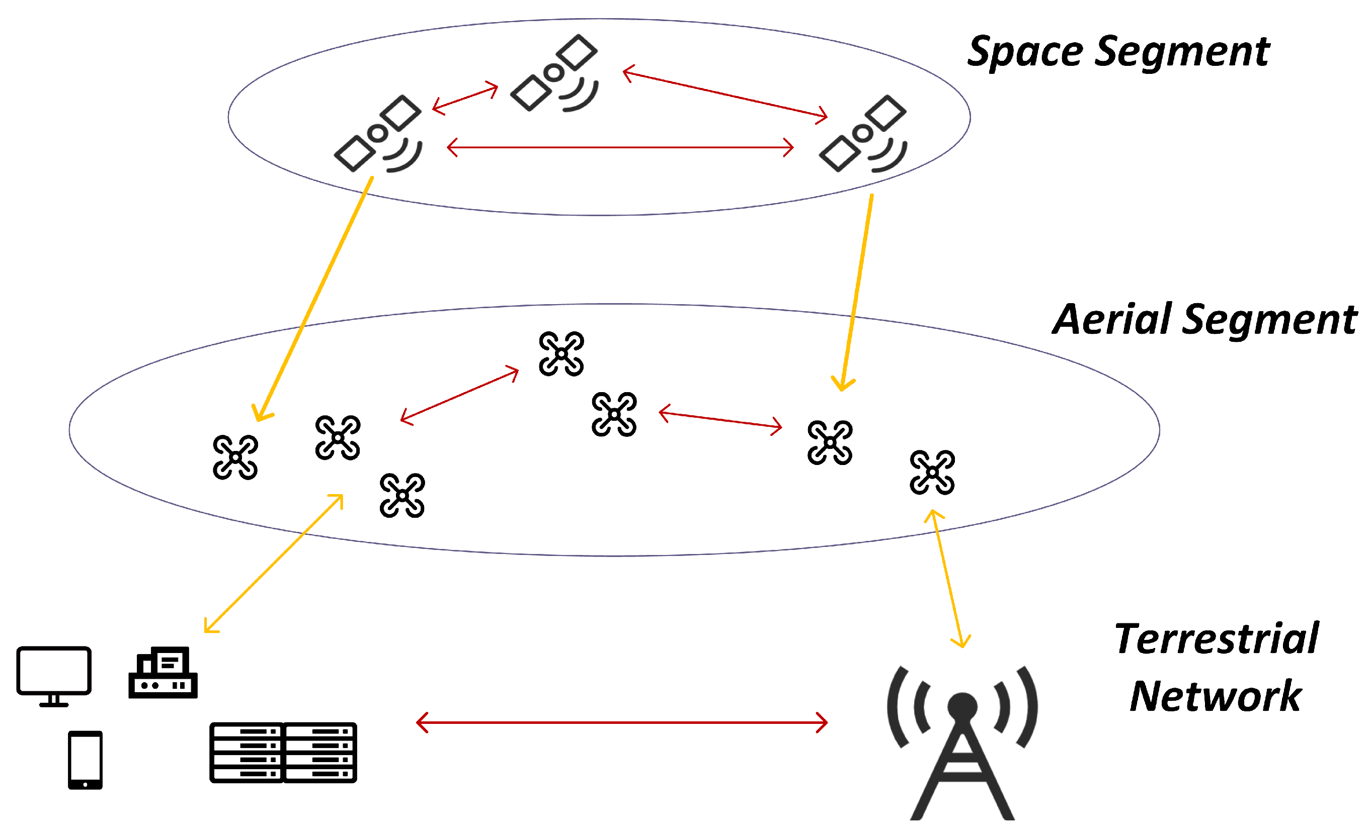
Figure 1, below, suggests a practical application scenario for SAGIN, where either segment has inner connections and is responsible for coordinating each other. As a consequence, however, SAGIN inevitably adopts different communication protocols in accordance with separated segments for maintaining its superiority regarding high capacity and data throughput [
14]. Hence, in order to refine the performance of integrated network, communication between UAVs and satellites as space-to-air propagation is acknowledged as a highly comparative factor.
Focusing on space-to-air communications, a lot of related studies have been performed to deal with all kinds of problems and challenges. Signal attenuation can be easily noticed, since there exists quite a long distance between UAVs and satellites, and the directions of the antennas are required to be adjusted to retain a higher gain [
15,
16], which is somehow beyond the issue discussed in our work. Meanwhile, such fast relative movements can cause a dynamic circumstance and lead to Doppler frequency shift. Adopting pseudo-random noise (PRN) code is a common method to estimate Doppler shift by determining the location of correlation peak through either a serial search or parallel search [
17]. The authors in [
18,
19] also applied signal detection techniques based on time-frequency signal analysis to compensate Doppler shift, such as short-time Fourier transform (STFT), continuous wavelet transform (CWT), etc. Additionally, the Doppler effect in frequency also changes orthogonal frequency division multiplexing (OFDM) signal waveform, and a kind of OFDM-modulated navigation signal is proposed in [
20] to provide a feasible solution. Latency is another factor diminishing the quality of the received signal, usually presented as multipath interference, which leads to the distortion of the autocorrelation function (ACF) of PRN code and then the failure of signal detection. Thus, delay mitigation and anti-interference techniques are studied in [
21], where a multiple gate delay (MGD) method employing three pairs of correlators has been considered to mitigating short-delayed multipath on signals using binary offset carrier (BOC) modulation, while the author only takes multipath into consideration without a highly possible dynamic environment.
Furthermore, standing in the field of integrated communication and measurement system research, where the theme naturally matches the background of space-to-air communication, scholars have conducted numerous related studies so far. Based on BOC modulation as an extend from original spread spectrum modulation offering better performance in measurement, reference [
22] proposed a combination with the introduction of a frequency-hopping technique as frequency-hopping binary offset carrier (FH-BOC) modulation to strengthen anti-interference capability, where multipath interference has also been discussed as outperforming the binary phase shift keying (BPSK) signal and BOC signal in circumstances. Subsequently, reference [
23] conducted a FH-BOC signal further, converting it into an efficient constant envelope multiplexing technique for easily integrating signal components, in which the results showed it possessing lower ambiguity and better multipath performance than other BOC signals designed in a constant envelope under the same conditions. Additionally, reference [
24] proposed a frequency-hopping alternated BOC (AltBOC) that inherits the low probability of interception, referring to another kind of variant BOC modulation, along with considerable anti-narrowband interference. Briefly speaking, scholars have already dedicated to the exploration in BOC modulation variant designed for ambiguity problems and interference confronting performance. However, there does not exist essential communication function for getting into involved with the measurement system in this research, even though anti-interference performance has been improved considerably. The authors in [
25] proposed a multifunctional signal consisting of measurement, navigation, and communication functions, based on BOC and BPSK modulation to simplify the receiver structure. Although anti-interference performance and large dynamic tracking performance are achieved in simulation, the information carrying capacity is limited to BPSK modulation, and meanwhile, the severe interference between inner signals happens at low carrier to noise ratio (CNR), leading to the downgrade of signal performance.
In this paper, a wireless communication system adopting I/Q modulation is proposed, in which a OFDM signal is modulated as an in-phase component and a FH-BOC signal is modulated as a quadrature component. Our work is contributive in following aspects:
To confront occasions according to our background where a considerable Doppler effect frequently occurs, which is difficult for the original OFDM signal to compensate itself by limited pilot-modulated subcarriers, and FH-BOC modulation is adopted due to its outstanding performance on auto-correlation function;
The most important motivations are to promote the resilience of the designed signal against interferences. Specifically, I/Q modulation offers capability that every interference affects in-phase component also inflicts the same influence on quadrature component. Therefore, certain favorable characteristics of FH-BOC modulation can be exploited for correcting OFDM symbols, in order to demodulate the OFDM signal component effectively and precisely;
Instead of using conventional pilot-based OFDM signal, we take an OFDM signal in which each symbol consists entirely of data-modulated subcarriers into implementation, and a quadrature component FH-BOC signal oversees the providing of channel estimation and valid compensation for the OFDM symbols. Hence, this way allocated a spectrum that can be utilized more efficiently, and the throughput capacity, compared to the original OFDM system, is improved consequently.
The remainder of this paper is organized as follows.
Section 2 demonstrates diagrams of both the transmitter and receiver and provides an overview of our proposed signal process.
Section 3 conducts a performance analysis of the designed system by discussing details, along with the characteristics and benefits through such implementation.
Section 4 provides simulation results to illustrate improvements of the designed system in the correlating aspects. Finally,
Section 5 draws the conclusions.
2. Overview of the Designed System
In this section, the construction of the designed signal is presented, followed by general descriptions and structures of the transmitter and receiver.
2.1. Signal Model
In order to utilize the spectrum efficiently, I/Q modulation is implemented to allocate and separate the OFDM signal and FH-BOC signal. As the quadrature branch, an analytical expression for the FH-BOC signal can be formulated as
within its period (
T = 1 ms), and
denotes the PRN code chip. Each chip duration is
, and the length of the spreading code sequence is
n. In our system, the coarse/acquisition (C/A) code is adopted as the spreading code, which has been used in GPS signals [
26]. Therefore, the code consists of
chips and is sent at
= 1.023 MHz, and the code sequence repeats every millisecond as the single period
T. The expression
represents the generation of the frequency-hopping square wave subcarrier with the same repeating period as the spreading code, which corresponds to the contemporary code chip and is formulated in sine-phased form as
where
is a specific subcarrier frequency. Additionally, a row vector
defines the frequency-hopping pattern, where
denotes the kth subcarrier frequency through equation
belonging to hopset
. The hopset includes every possible single subcarrier frequency and can be presented by
as a monotonical increasing sequence, where
d is the minimum frequency-hopping interval. According to [
22], each subcarrier frequency
is bound to be an integer multiple times that of
. In other words, the hopset only contains an integer number, and the frequency-hopping pattern
is a decimal sequence controlling the frequency hopping, which is initialized at the very beginning.
As for the in-phase component, a single OFDM symbol can be expressed in its discrete form as
where denoting
kth data symbol as
that has been normalized as
and N-point inverse fast Fourier transform (IFFT) is performed. The duration of the single symbol
is equal to
. In order to achieve overlapping spectrum peaks, the subcarrier spacing
must be identical to the minimum frequency-hopping interval
. Generally, when
, it can be determined that
and, consequently,
= 1/1023
s. Then, the cyclic prefix (CP) insertion is required to meet the guard interval, which can be interpreted as
where the length of cyclic prefix is decided as
.
Discrete OFDM symbols require up-sampling, since the sampling rate must surpass twice that of the carrier frequency to meet the Nyquist criteria. Additionally, itself must surpasses all the subcarrier frequencies in the OFDM symbols, which reach their highest frequency at . In comparison, the FH-BOC signal can realize up-sampling easily by repeating, because each sampling point is located in its corresponding spread code chip, leading to identical value within every chip duration consecutively. The up-sampling method on OFDM symbols is generally zero-padding or zero-inserting, which extends the input sequence by appending zeros before the IFFT process. However, such a method has a limitation that enlarged size must be equal to a power of two, which causes a mismatch on most sampling rates if there are any up-sampling points, except a power of two in a single OFDM symbol. To develop compatibility, the raised cosine filters are adopted as matched filters for up-sampling OFDM signal, turning discrete OFDM symbols into a continuous one, as . Now, we present the frequency-domain description of the matched filter as , and also the impulse response as . Additionally, for the sake of clarity, the expression on matched filters will be discussed in next section.
Hence, the combined signal can be described as
where
means the convolution of OFDM signal and the impulse response of the matched filter,
is carrier frequency. Additionally, the parameters
m and
n, which have been normalized by
, are the coefficients for adjusting the power ratio between the in-phase component and quadrature component.
2.2. Transceiver Structure
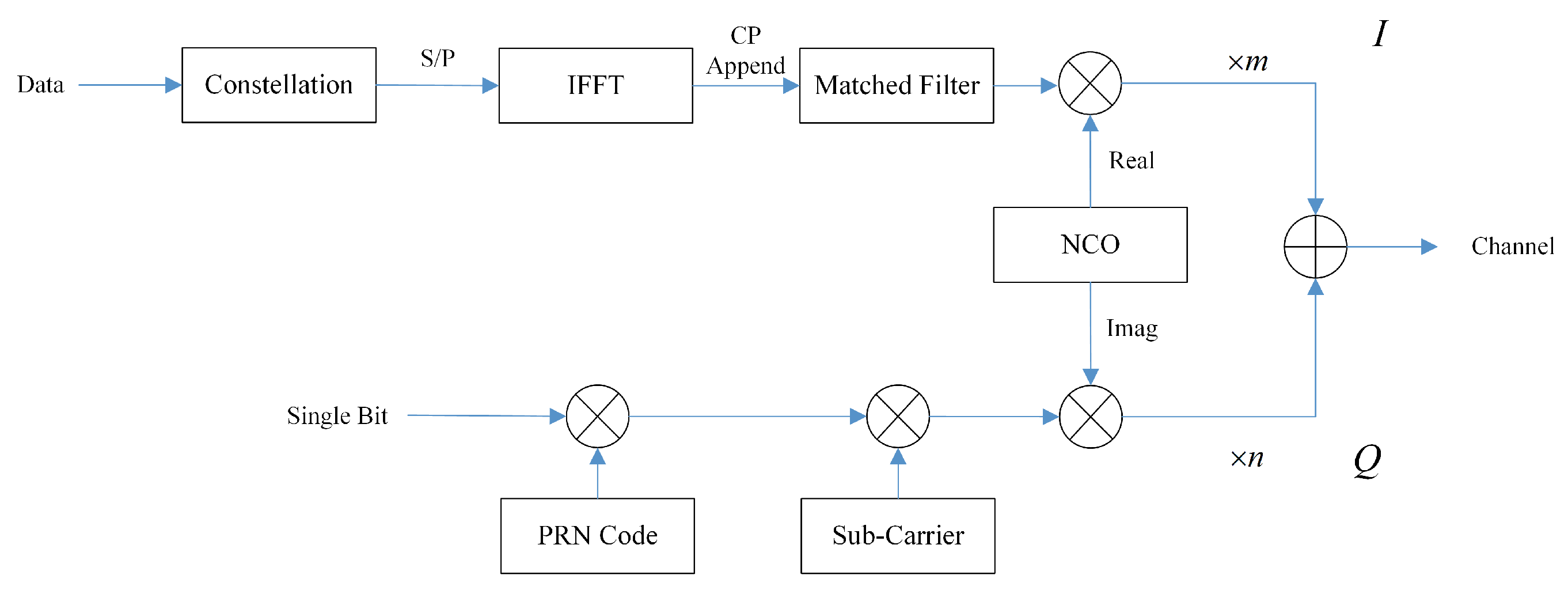
The following discussion is erected on the designed signal construction, and the transmitter diagram is depicted in
Figure 2. For a quadrature branch, every single bit gets spread by PRN code at first, and then is modulated by local sub-carrier to generate a current FH-BOC signal. For the in-phase branch, a constellation is required for converting a series of original binary data bits into coded data symbols, which has highly promoted transmission efficiency, such as phase-shift keying (PSK) and quadrature amplitude modulation (QAM). These data symbols are arranged from series into parallel before IFFT and are CP appended after IFFT. Then, the complete OFDM symbols need to implement up-sampling, as mentioned earlier, through convolution with the impulse response of the matched filter. The numerically-controlled oscillator (NCO) generates sin wave or cosine wave in high frequency as the main carrier, where its real component is passed to the in-phase branch and the imagine component is passed to the quadrature branch. At last, the two signals are added up and sent to the channel.
The receiver design is depicted in
Figure 3. The main target is to exclude interferences from the unpredictable channel, meanwhile achieving valid separation of the combined signal based on the characteristics of the transmitted signal. At the beginning, there is a band-pass filter for allowing through transmitted signal within a specified frequency band and blocking components with the outside-band frequency. Then, the received signal is duplicated and delivered into both the in-phase and quadrature branch.
Delivered signals need a down-conversion from carrier frequency to a lower frequency at the baseband, which is achieved by multiplying with prompt local carrier from NCO. After being processed through a low-pass filter, the FH-BOC signal, as the quadrature component, needs an acquisition procedure, since it is obscure to find the exact Doppler shift and spreads code delay. Then, the tracking process is necessary for using the acquisition results to continuously synchronize a local replica of the spreading code and carrier with the received signal. Additioanlly, as for the in-phase component, the OFDM signal is required to go through a matched filter, in order to alleviate the negative influence from Doppler shift. After sampling at the symbol rate (with CP removing), the FFT procedure, and from the parallel to serial conversion, at last, the decipher on constellation mapping is demanded to recover transmitted data bits.
3. Performance Analysis
This section will mainly focus on the performance analysis of key aspects of the proposed system, including its acquisition scheme, tracking loops design, and matched filters’ improvement to signals.
3.1. Acquisition Scheme
The acquisition for FH-BOC signal is a search process containing a three-dimensional search on Doppler shift, spreading code, and a unique frequency-hopping pattern, which requires an additional searching dimension, compared to ordinary spreading signal. Generally, there are serial code search acquisition [
27], parallel frequency search [
28], and parallel code-phase search [
29] serving as spreading signal acquisition scheme. Additionally, in order to accelerate the acquisition procedure, a parallel code-phase search is adopted, and the block diagram is shown in
Figure 4. The input signal
is the output of the preceding low-pass filter, and to perform a circular correlation with a local replica of the sub-carrier and PRN code in the time domain, which is presented as multiplication after FFT in the frequency domain. Then, after IFFT, the convolution results under different code-phase situations can be examined at the same time, which corresponds to a single preset Doppler shift frequency. As for the FH-BOC signal, the additional frequency-hopping search dimension has a great effect on the acquisition time and complexity to those who intercept and decipher signal unauthorizedly [
30]. By defining the period of
as the same as a period of the pseudo-random noise code sequence
T, aligning these two parts uniformly can be achieved, in order to reduce the unnecessary time cost of calculation and complexity of demodulation, since the pattern can be derived from the spreading code phase in the meantime. Furthermore, coarse estimations of code phase
and Doppler shift
will be regarded as initialized parameters, transferred to the following tracking loop and renewed for every period
T.
The validity of our proposed system depends on the stability of the FH-BOC signal, which basically refers to the auto-correlation function. It can be expressed as
where
denotes the ACF of spreading code. Supposing an ideal PRN sequence that possesses zero cross-correlation function (CCF) serves as the spreading code, then it has
Hence, the ACF of FH-BOC signal can be derived as
which is the ACF of frequency hopping pattern
. Since adopting a cyclic repeating subcarrier pattern with the same period as spreading code, it can be concluded as
In the meantime, it can be inferred that
where
satisfies the equation demand, referring to
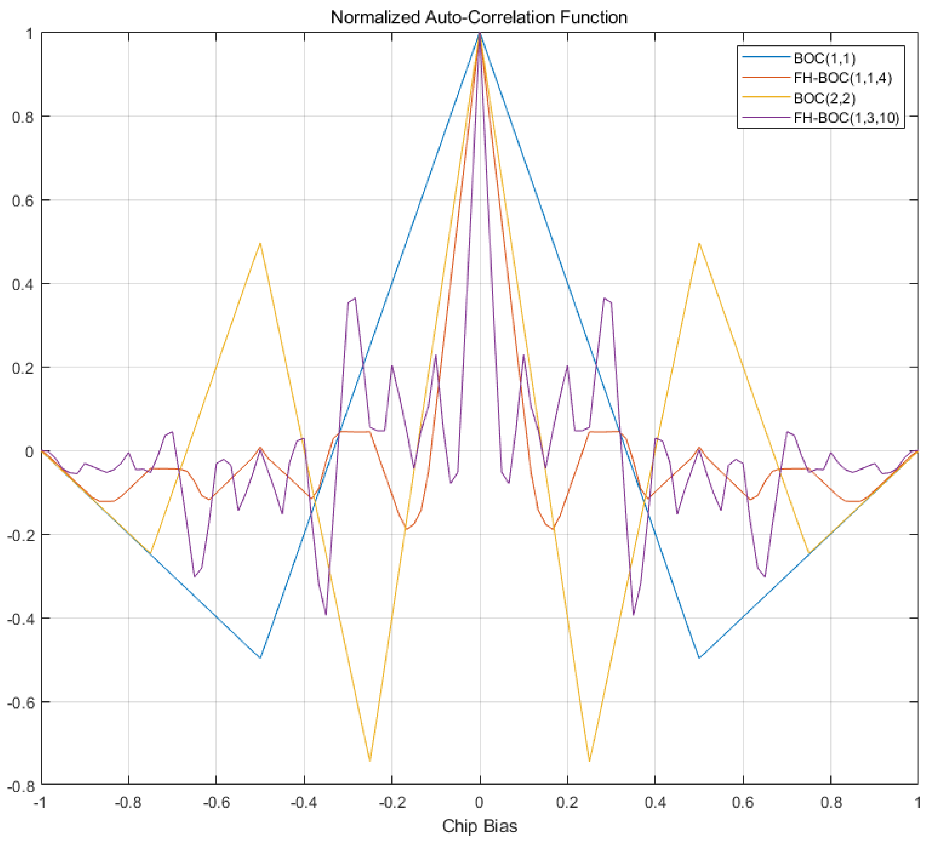
. The simulation result on ACF of the FH-BOC signals, compared to the BOC signals, within a single certered chip duration is demonstrated in
Figure 5.
The main peak-to-maximum side-peak ratio (MSR) is an important factor in dealing with signal acquisition. In order to avoid Type I and Type II errors, and meanwhile, to improve system performance in occasions with considerable noise, MSR is a critical indicator for mitigating the ACF peak ambiguity problem and evaluating the capability of anti-interference. A higher main-peak for a maximum side-peak ratio indicates a cleaner, more stable signal with less unfavorable noise or distortion. Majorly, compared to the signal, as shown above, apparently the signal produces a smaller MSR to gain a better performance on the signal acquisition. Additionally, the signal shows one more side-peak than signal; meanwhile, it leads to a larger fluctuation near the main peak. Additionally, the ACF illustration of performs a complex distribution that changes rapidly, along with a greater MSR, compared to the signal, which refers to a minimum frequency-hopping interval increase, which imposes worse ACF performance.
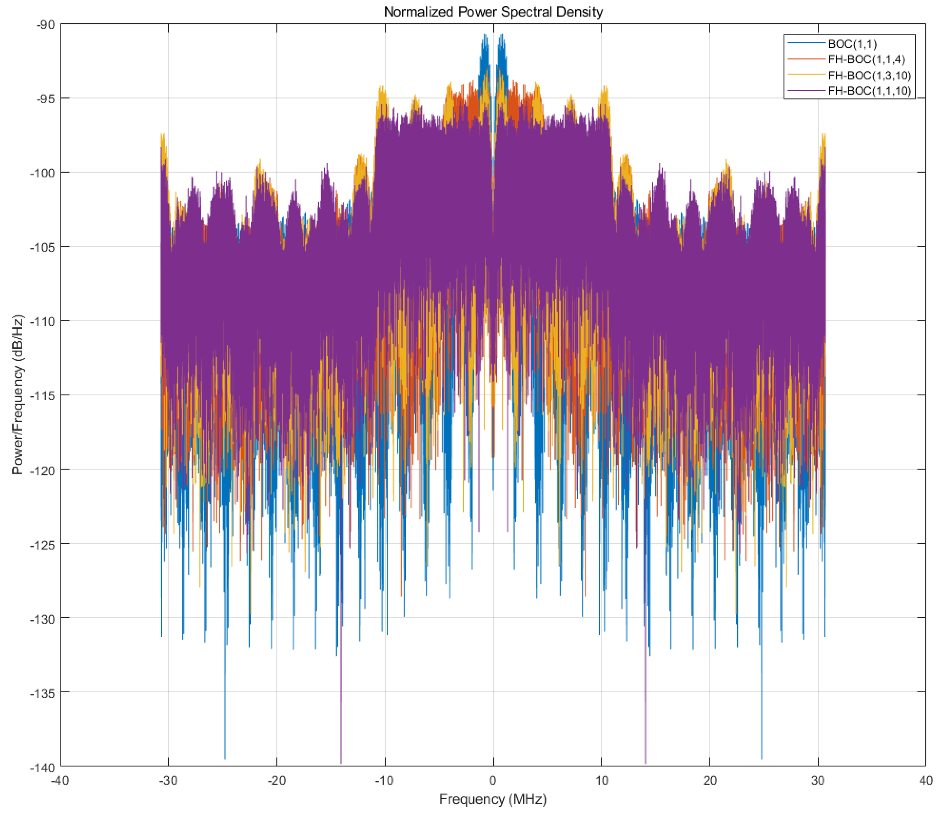
Additionally, since BOC modulation generally appends the subcarrier into ordinary spread spectrum modulation, where the subcarrier generation is of single frequency and can be regarded as a special case of FH-BOC with the hopset containing only one element, the power spectrum density transition between is plainly intelligible, as shown in
Figure 6. It can be discerned that the
signal possesses its PSD, as divided by two of the spread spectrum signals spliting into two main power spectral peaks, and the FH-BOC signals show either PSD extended further to split into more pieces than the BOC signal. The PSD of the
signal possesses continous peaks limited within about 5 MHz, and the
signals containing four interval peaks, where their spectral peaks are located at the same level of power/frequency, due to identical quantity of peaks. Meanwhile, the
signal’s major power distribution has been extended over 10 MHz, similar to the
signal, although the former’s power spectral peaks seem to be lower than the latter’s. Generally speaking, the denser the subcarrier frequency presented in the hopset, the less distributed energy carrying there is on each power spectral peak. Such a characteristic conveys the manipulation way of adjusting power allocation in the frequency domain, and it provides a feasible solution for coordinating the OFDM signal in I/Q modulation with different data channels distribution.
3.2. Tracking Loop
The tracking loop is aimed at synchronizing the local replica of the spreading code and carrier with the current received signal for demodulating the next incoming signal as accurately as possible. At the very beginning, the output of NCO is determined by the acquisition results of Doppler shift
and the output of the PRN code generator by the code delay
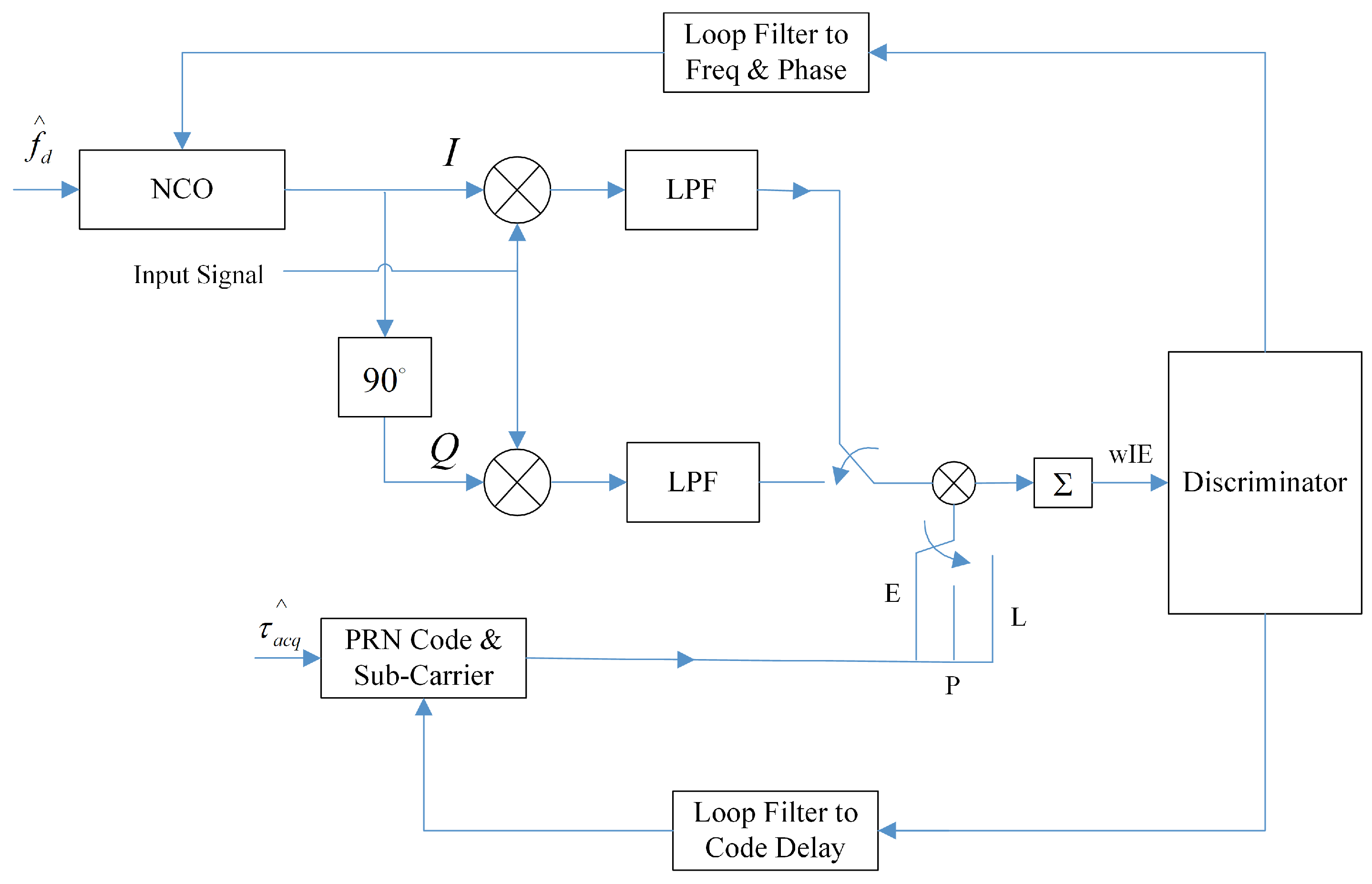
, as shown in
Figure 7.
For the start in each accumulation time period , the output of NCO is required to duplicate itself and adjust its phase to quadrature; then, the input signal needs to be multiplied by local carrier as demodulation. The following LPF is for filtering a high-frequency component and persevering the baseband signal only. Since the output signal from LPF itself is still spread with the PRN code, and code-phase has been affected by the transmission distance and Doppler shift, it is necessary to set the mismatched PRN code replica as early and late, suggested as E and L for abbreviations. Either code alters its code delay half chip from the prompt code, in order to find out which code-phase is the most correlated with the incoming signal. Through all kinds of combinations, the accumulation of the output from different correlators provides certain control words, e.g., shown as , as inputs of subsequent discriminator. The discriminator processes these control words to offer measurable quantities, and loop filters are responsible for reducing the noise in the discriminator’s outputs. Finally, the renewed parameters on the carrier and PRN code of the received signal are sent back to the NCO and code generator, waiting for an incoming signal in next time period.
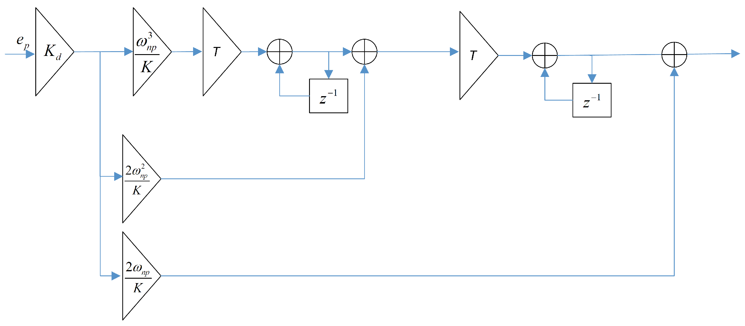
Discriminators and loop filters are designed distinctly for different lock loops. For phase-lock loop (PLL), its discriminator can be designed as the most common one, given by
which is optimal for phase estimating, compared to the classic Costas loop discriminator, while requiring a relatively high computational complexity. Then, the implementation of loop filter must take the order of filter into consideration at first, since it can directly determine the loop’s dynamic response towards the input signal. A higher order generally leads to more compatibility, with complex relative movement situations, although, in the meantime, it also produces a process delay. Additionally, a second-order loop filter is mostly introduced for being sensitive to acceleration stress. Additionally, the noise bandwidth is significant because it directly determines the difficulty tracking the instant baseband signal and the volume of incoming noise. It is assumed that the total loop gain is
, which consists of
from the discriminator and
from the NCO. The transfer function of our designed loop filter can be presented as
where
represents the undamped natural frequency. By mapping from continuous a S-Domain to discrete Z-Domain through the equation
that
represents tracking loop’s renew interval. Thus, the discrete transfer function can be derived and presented as
The structure of loop filter in PLL is shown in
Figure 8, and input
is the output of phase discriminator.
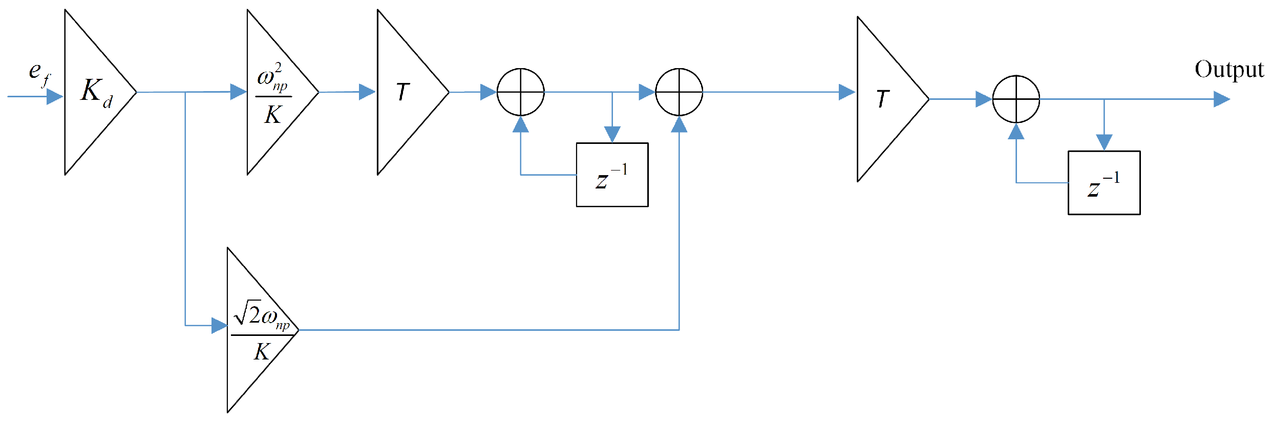
The frequency-locked loop (FLL) is quite similar to PLL in many ways, while it is dedicating to resolving the presence of external disturbances or frequency drift for retaining a stable and accurate frequency for synchronization. The key differences between are accuracy and complexity. Although PLL is generally more accurate than FLL in maintaining a constant phase relationship, FLL is typically faster and more responsive to tracking changes in the reference frequency, due to the lesser components requirement at a lower filter order. In the meantime, PLL exerts better if the FLL has been tracking the signal frequency steadily, and that signal phase can be further determined through frequency difference reduction. There are several types of discriminators commonly used in FLL design, including the phase detector, the zero-crossing detector, and the costas loop. The error detects an algorithm of a zero-crossing detector, which can be shown as
where
and
products are determined by control words. The
product is generated through
and
product can be presented in
where the preceding control words that have been delayed for a single time interval are demanded to be put into the calculation. Since the loop filter order of the FLL is lower than PLL’s, the transfer function of applied filter is
and the diagram of loop filter is shown in
Figure 9, where the discrete transfer function through the same mapping relationship can be presented as
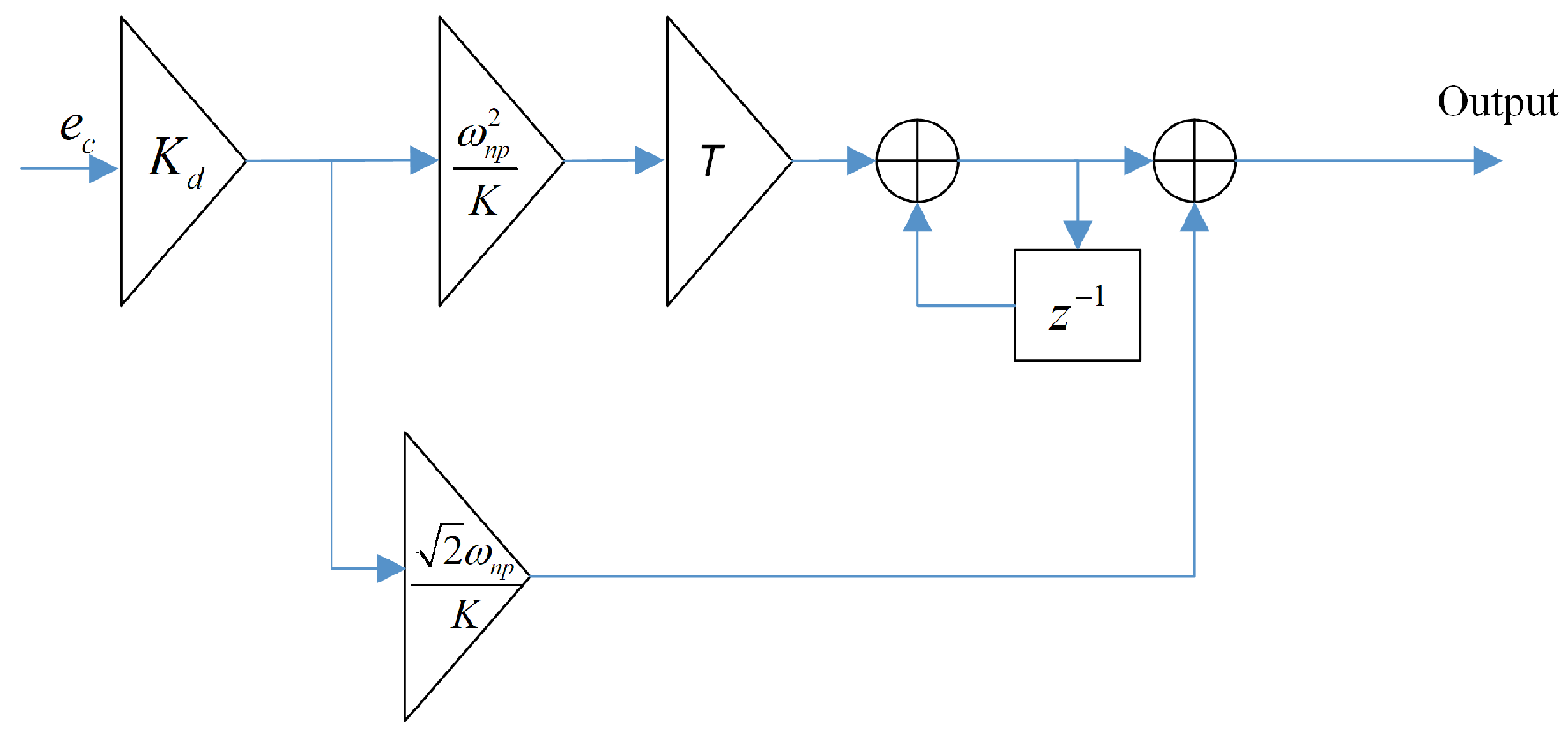
Delay-locked loop (DLL) is erected on previous the PRN code acquisition procedure. Since the code phase delay has been approximately synchronized, where the accuracy is at the level of an entire code chip, it is indispensable to determine whether the delay is somehow early or late within a single chip. Thus, early, prompt, and late codes referring to the phase relationship are demanded, as shown in
Figure 7, and either code is a half chip that deviated from the prompt code. The most commonly used kinds of discriminator in DLL are non-coherent early minus late power (NELP), dot product, and normalized early minus late envelope (NEML). Additionally, the normalized NEML discriminator is implemented, due to its robustness and simple implementation, to remove amplitude sensitivity. Such a discriminator algorithm is defined as
where
represents the early correlation power, and
represents the late correlation power. For our adopted loop filter of DLL, the transfer function is
along with its Z-domain formulation as
Additionally, the diagram of DLL’s loop filter is shown in
Figure 10.
3.3. Matched Filters
The idea of matched filters is widely implemented in digital communication system, in order to achieve various purposes, such as SNR improving [
31], pulse shaping [
32], or out-of-band emission reducing in certain multiple-input multiple-output (MIMO) scenarios, such as Universal filtered multi-carrier [
33] and filtered-OFDM [
34]. The dynamic channel condition causes frequency-selective fading and Doppler frequency shift, leading to inter-symbol interference (ISI) and inter-carrier interference (ICI) [
35], which impose distortion on the OFDM signal waveforms. Although the FH-BOC modulated signal is capable of avoiding such problems, the OFDM signal requires multipath interference suppression and waveform restoring. As for our proposed system, the square-root raised cosine (SRRC) filters, which are two parts divided from raised cosine filter, are adopted for pulse shaping on the OFDM signal, being capable of mediating negative affection. The normalized frequency response of raised cosine filter
is a piecewise-defined function for
, where
is a roll-off factor and
is the reciprocal of symbol rate. The crucial is the roll-off zone between, which is determined by
controlling its smoothness and bandwidth. Correspondingly, the impulse response of this filter
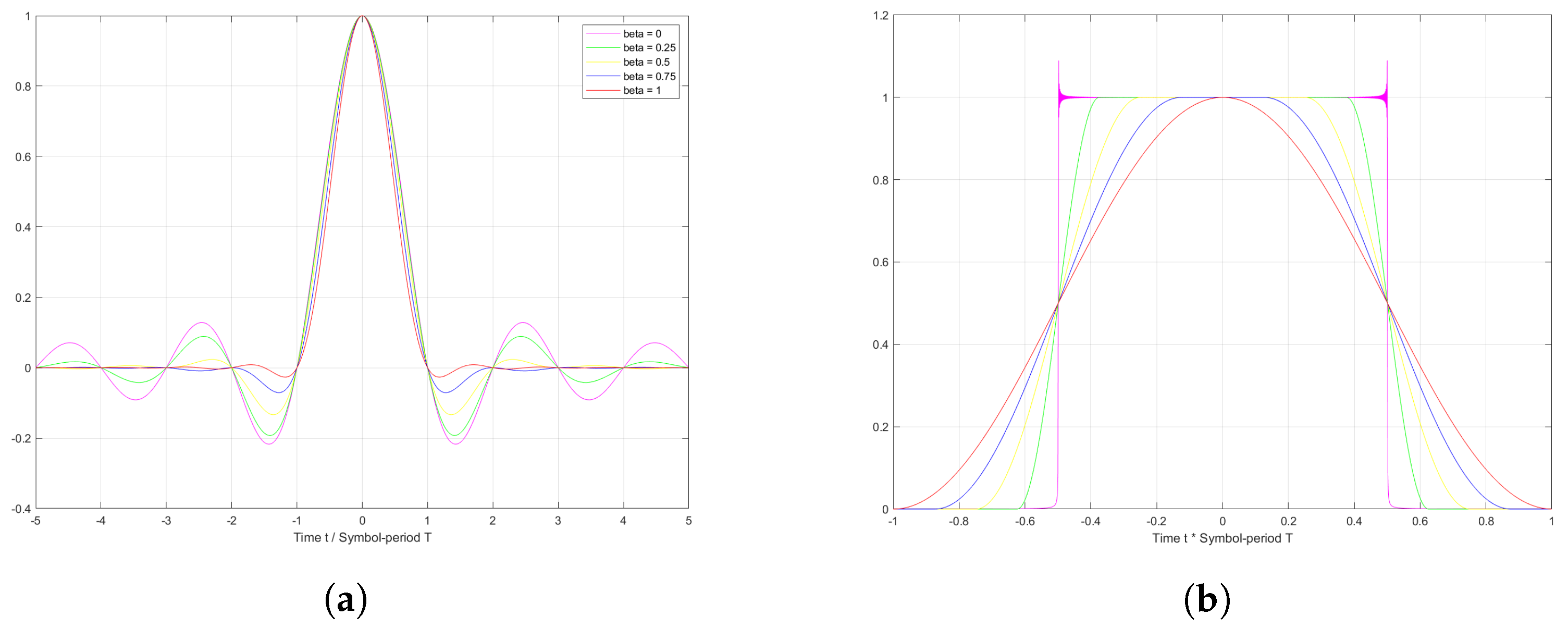
is a sinc function shape, both waveforms have been plotted in
Figure 11. Additionally, it can be recognized
has zero-crossings at multiple times of
, so that every previous sampling decision remains no interference on current sampling one, referring to its capability of eliminating ISI during symbol stream. Therefore, raised cosine filter itself is generally split into two square-root raised cosine filters and being applied in both transmitter and receiver. Separated filter parts are required to satisfy the equation
, which leads to
.
However, there exists the Doppler shift that has been changing the signal waveform, making the matched filter no longer able to realize the ISI cancellation on the received signal. Therefore, ISI minimization is an alternative and feasible solution for confronting Doppler effect instead, which is accessed by adjusting value of the roll-off factor
. In fact, the characteristics of the raised cosine filter vary with different roll-off factors and can be noticed in
Figure 11. When
approaches 0, the roll-off zone gradually becomes narrow, as
is almost into a rectangular shape in frequency domain; meanwhile,
has been a complete sinc function shape. As
, the frequency response
is a pure raised cosine, and the impulse response seems much flatter at every other sampling time. Practically, the pulse shape
only has finite support in time, for it has been truncated by spanning symbols. The result of truncation is the emergence of non-zero side lobes of frequency response, that the PSD fluctuates in waves beyond the roll-off zone. Additionally, the smaller the factor
is, the better the side lobes suppression that can be achieved, which is a contradiction to the desired flat impulse response. Additionally, even though ideal SRRC filters are not realizable in realistic [
36], making use of them still earns benefits. In fact, an intuitive pulse shaping illustration of matched filter is suggested in
Figure 12, with waveform comparisons for both the real component and imagined component within a short time. The vertical lines represent the original data bit required to be upsampled, and the magenta line standing for zero inserting output is achieved through the IFFT process. The blue line is the output of the square-root raised cosine filter in the transmitter, which deviates from the transmitted data a distance. Meanwhile, the cyan line represents the perfect recovery for SRRC filter’s output in the receiver without interference, which is approaching the green line, and the output of a raised cosine filter designed in front of the receiver, while overlapping for the most of time. We can identify that the comparison in waveform formation between SRRC filter’s output and zero inserted output is quite prominent in presenting less fluctuation in the amplitude, referring to the capability of better handling the effect Doppler shift imposed on the sampling decision.
Supposing the Doppler effect has inflicted relative frequency shift
on the received signal, a series of sampling points in the time domain gradually deviate from the original ones. We use verify the alleviation implemented through a raised cosine filter, using a root-nean-square error (RMSE) function on deviated samples to comparing with the zero inserting method that is normally employed to achieve over-sampling. The
function can be expressed as
where
N is the length of original sampling sequence
,
is a sampling-lagged sequence waiting to be tested, and 2-norm function is performed on absolute difference. Established on over-sampled OFDM baseband signals within a single period and without stochastic noise, they have been aligned to original discrete OFDM symbols at the very beginning. To choose a balanced factor,
and verified results, in comparison between the filtered OFDM signal by matched filters and zero-inserted OFDM signal, are demonstrated in following
Table 1.
Under different Doppler shift conditions, it can be concluded that either value of has increased with larger relative shift . Such a tendency gradually slows down when the Doppler shift comes to above 1000 Hz, and at each level it always has . The comparative ratio , raised cosine filtered over zero inserted , reaches its minimum value of at 250 Hz Doppler frequency shift and maximum value of at 20,000 Hz. Additionally, explaining comparative ratio as another factor for measuring how much Doppler effect has been alleviated and reduced, e.g., at 400 Hz raised cosine filtered is less interfered with by than zero inserted , which is quite a half alleviation. Although near the level of 20,000 Hz, a large Doppler shift behaves similar to for only reduction, and speaking from a positive view, it has among these Doppler situations and a raised cosine filter showing much more effective in a small Doppler shift situation. Generally speaking, up-sampled OFDM signals through a raised cosine filter are more stable whenever there exists a Doppler shift, especially a relatively small one, for demonstrating its superiority on pulse shaping property.
4. Simulation Results
This section will mainly provide the numerical results of the Type I and Type II errors and uncoded bit error rate (BER) for the AWGN channel with relative movement between satellite and UAV. Based on the Doppler effect formula
where
represents the relative angle,
is the relative velocity, and
c is the speed of light, from which we can figure out the Doppler frequency shift
and relative shift
. Supposing
in the occasion of maximum relative velocity, that
equals to 12.5 km/s larger than low earth orbit (LEO) velocity 7.8 km/s as trying to enter or leave the orbit, which is gradually accelerating and causes a stepping Doppler shift from a random small number up to about 640 Hz. Additionally, since I/Q modulation is adopted, intending to overlap signals’ power spectrum in the frequency domain,
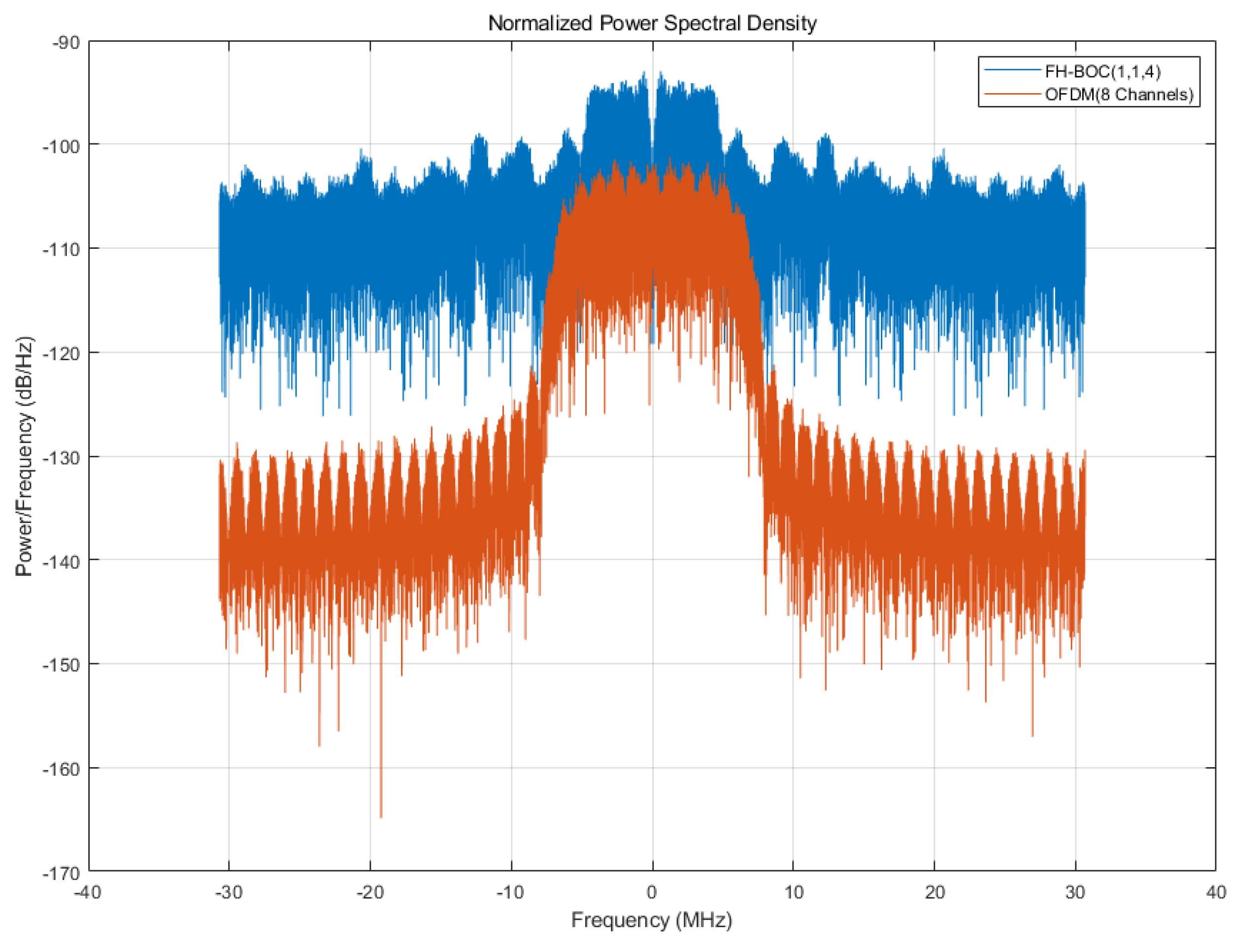
Figure 13 suggests that the majority of both PSDs limited to the boundary as nearly 10 MHz with shape peaks almost blending, in order to efficiently exploit valuable bandwidth resources, which, meanwhile, leads to the necessity of the designing signals’ power allocation, according to the fact that the original generated power of FH-BOC signal surpasses over 10 dB/Hz of the OFDM signal for the majority power distribution part.
Type I and Type II errors, also referred to false positive error and false negative error, are usually introduced to examine the probability of correctness in statistical testing. In our proposed system, the validity of the signal detection scheme denotes an important characteristic, since not only is taking several two-dimensional searches within anterior failures is unacceptable coming to realistic communication system, but also demodulating contemporary OFDM symbols is not feasible without code phase alignment and frequency compensation. The inspected results on our designed signal acquisition procedure performance over different
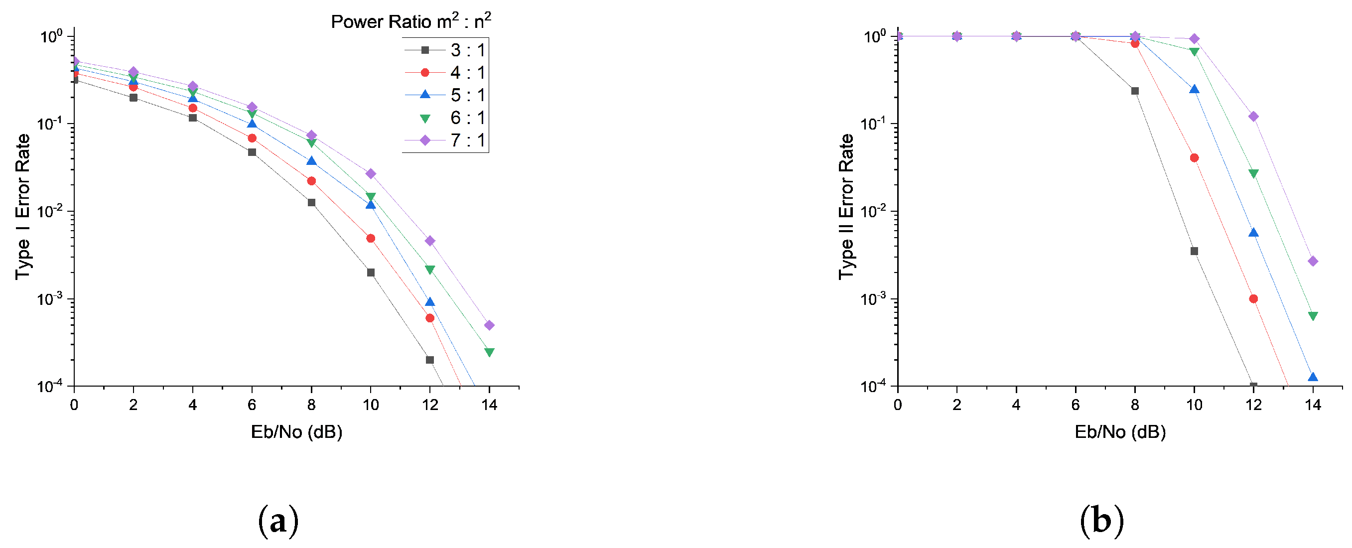
and power ratio, which represents power of OFDM signal over power of FH-BOC signal, are demonstrated in
Figure 14.
It can be noticed that the Type I in
Figure 14a or II in
Figure 14b error rates gradually go down, along with the increment of
. Additionally, we can identify that the general performance on the signal acquisition gradually falls as the value of the power allocation ratio increases, which means the one with a higher power allocation to FH-BOC signal outperforms others. As a result, the one power ratio of
:
= 3:1 is the most prominent, as when
= 12 dB, and either error rate has nearly reached the level of
. Based on the reliability of acquisition procedure, the performance on the stability of the tracking loop is demonstrated in
Figure 15. Through the estimated parameters of phase, code delay, or frequency condition, in accordance to the real imposed interference, the difference between for every milli-second period is suggested intuitively. Either estimated parameter undergoes a short period of measuring the adjustment as tracking of the phase
in
Figure 15a, code delay
in
Figure 15b, or spur occurred as frequency
in
Figure 15c, then turning into a plain and stable condition with little fluctuation, such as an absolute difference limited to a near
length of a single PRN code chip in the code delay tracking.
Therefore, the power distribution shown in
Figure 13 guides that a well-balanced allocation of power towards the in-phase signal and quadrature signal should be taken into consideration because the former is certainly capable of measuring the carrier frequency and providing sampling time localization for the OFDM signal, while trying not to inflict excessive influence on its demodulation as possible. In the meantime, the latter should not involve the code tracking procession, which otherwise behaves as extra noise during the demodulation of the FH-BOC signal. The performance on the BER over different power ratios
:
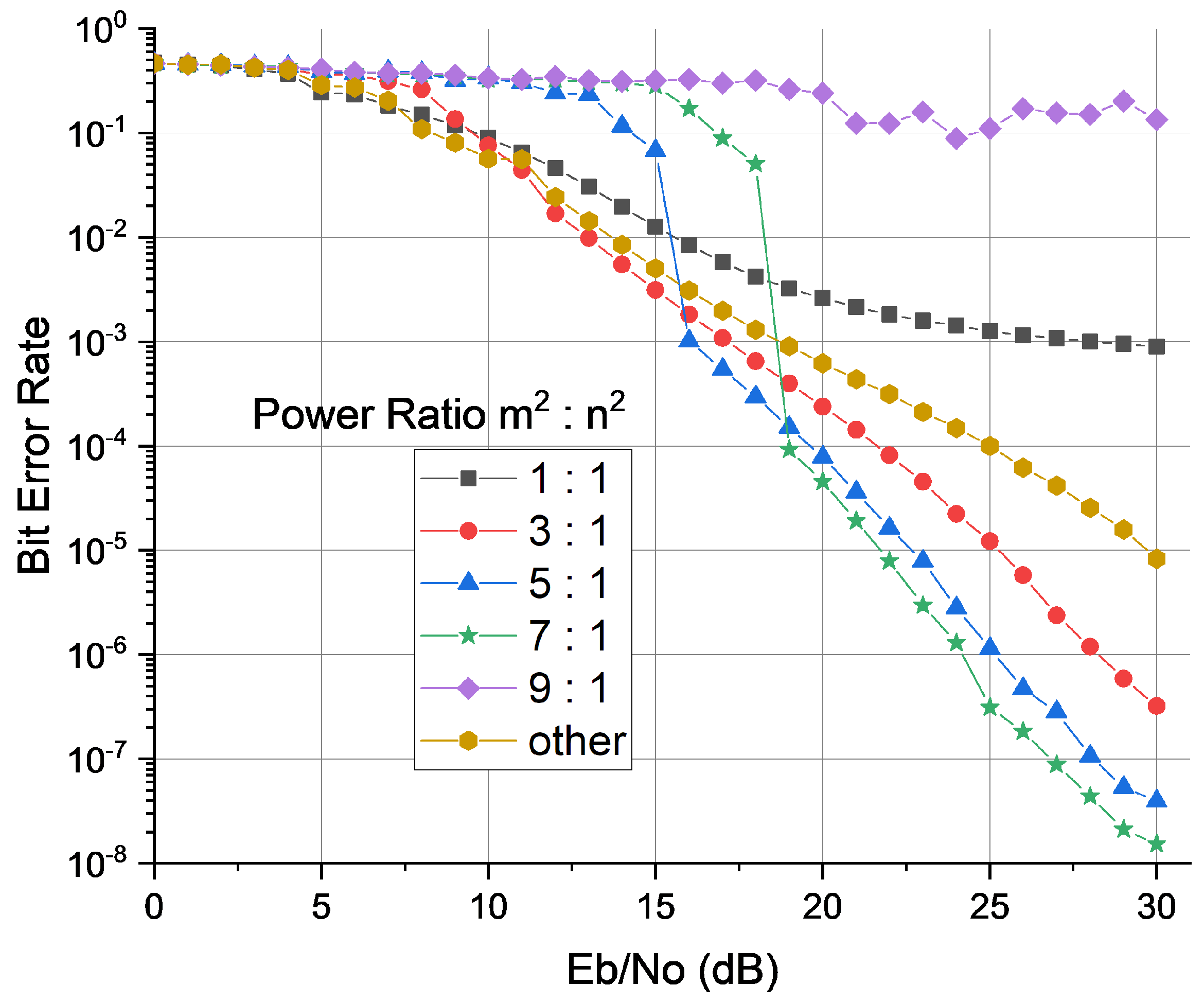
is depicted in
Figure 16.
Generally, it can be identified that the BER performance behaves better, with the
and power ratio increasing. However, an exceptional one is the power ratio of
:
= 9:1 for it holds near BER of
, regardless of the value of
, mostly due to an inappropriate power ratio, since only
power has been allocated to FH-BOC signal, which brings acquisition and tracking loop difficulty for achieving detection and signal alignment. As a consequence, such an unfavorable condition causes OFDM symbol demodulation failure. Additionally, the power ratio equal to 7:1 is the one outperforms the rest, which almost tells us that an appropriate power allocation has been found. In the meantime, we can identify that the most prominent one does not always beat the BER performance, since below
= 15 dB, it behaves worse than others, e.g., the power ratio of 5:1 also behaves worse than either 3:1 or 1:1 below the condition
= 12 dB. Such performance rapture emerges at smaller
for lower power ratio as an abnormal phenomenon, mainly because the detection scheme of the FH-BOC signal demands that it should surpass a certain energy threshold. In other words, when less energy allocation belongs to the FH-BOC signal as a power ratio raising, in order to reach the signal acquisition threshold, a larger
is required. As the comparison to our proposed signal on BER performance analysis, a pure OFDM signal denoted as “other” in
Figure 16 has been tested in the same simulation environment, with an original pilot symbols arrangement and correlated signal compensation algorithm on frequency and phase. It can be evaluated that our proposed signal, the one with the optimal power ratio allocation, behaves better than the pilot-inserted OFDM signal when
> 18 dB. At the BER level of
, our optimal signal requires about
less on
in the performance comparison.
