Abstract
The objective of this study was to assess coastal dynamics of the Sinai Mediterranean coastline (SMC) between 1990 and 2020. In this study, remote sensing imagery and geographic information systems-based spatial computing methods were used for coastline change analysis. The study found that the SMC experienced major morphological changes during the period of study. The results show a spatial heterogeneity of coastline change rate over the study period with some periods of rapid change and other periods of stability. The overall analysis during the period of study indicated that the coastline has retreated landward approximately 555 m; the average annual erosion rate was 2.5 m/year. The percentage of the eroded section in the coastline is 60% with the remaining 40% either advancing or remaining stable. Sections of the coastline accreted as much as 542 m. The GIS-based DSAS model application used in this study is unique because it measured spatial variations of coastline dynamics over time using a multiple statistical approach.
1. Introduction
Coastlines change due to various natural factors, such as beach erosion, floods, and sea level rise. Recently, climate change, coastal processes, and human interventions are causing morphological changes in coastlines [1]. Change of coastline position has become one of the major environmental problems in the last several years. Research indicates that most of the global coasts are retreating with an annual erosion rate of between 1 cm/yr. and 10 m/yr. [2]. Mapping spatial and temporal change of the coastal environment has become easier due to remote sensing and Geographic Information Systems. Maps can display the spatial variations of coastal erosion/accretion and make future predictions to help decision makers make good decisions [3]. Moderate-resolution satellite (MRS) images, such as Landsat, have been used to monitor changes of coastlines position since the early 1970s. MRS Landsat imagery delivers repeated and consistent statistics that can be used for quantifying coastal variations [4].
MRS imagery offers several advantages, such as up-to-date data availability, and multi-temporal archive records covering the Earth with imagery and availability at no cost for users [5]. MRS imagery was widely used for coastline monitoring and mapping because it has spectral and radiometric information which contributes to accurately automated coastline extraction [6].
Landsat images including the Landsat-5 TM (Thematic Mapper), Landsat-7 ETM+ (Enhanced Thematic Mapper Plus) and Landsat-8 OLI (Operational Land Imager) are increasingly used for coastline change detection. They have been used globally in several coastal studies. Various water indices have been developed for mapping water bodies. The remote sensing ratio between near-infrared and green spectral bands have been used to develop the Normalized Difference Water Index (NDWI), to accurately detect and map land/water features from remotely sensed multi-spectral imagery [7]. It was effectively applied by several studies to delineate coastline from a multi-temporal Landsat imagery in non-populated coasts [8,9]. Urbanized coasts are problematic because they are “noisy” with very little homogeneity. Xu [10] exchanged the middle-infrared instead of near-infrared band to solve the problem of the noisy results due to urbanization.
In this study, spectral water indices such as NDWI and MNDWI were uniquely applied to discriminate and map water bodies from land features and to analyze the changes in a coastline along the SMC for a 30-year period based on multi-temporal Landsat imagery. ArcGIS software-based spatial computing uses the USGS Digital Shoreline Analysis System (DSAS) model. To achieve the objectives of this study, three spatial statistical approaches were used to compute rates of coastline changes such as Net Shore Movement, End Point Rate and the Linear Regression Rate.
Coastal dynamics along the SMC have been assessed by several studies. Frihy et al. [11] compared aerial photographs taken in 1955 with topographic maps produced in 1992 to detect coastal changes. Frihy et al. [12] studied the effect of Arish Power Plant on beach erosion using hydrographic surveying techniques along the El Arish coast. The El Tineh Bay coastal zone was studied by comparing historical topographic maps made in 1973 with MRS images taken in 1984 and 1996 [13]. El Banna et al. [14] used MRS images taken in 1986 and 2001 to analyze the variation of coastal erosion and accretion rates along selected parts of SMC. Nassar et. al. [15,16] used MRS images to detect changes along the SMC between 1989 and 2016.
The analytical approach of this study is different from previous studies of the SMC because our study focused on the spatiotemporal coastline change analysis using time-series Landsat imagery with equal intervals of 5 years (seven periods). The result from our study is focused on trend analysis along the entire SMC over time linked with both natural and anthropogenic driving factors. The study of Nassar et al., 2018, measured coastline change rates between 1989 and 2016, while our study measured in detail, the coastline change rate seven times in order to analyze the trend of the coastline change rate.
This study used a Landsat time-series with 5-year intervals to compute spatial and temporal change analysis of coastlines for coastal management. It performed an up-to date analysis of coastline change over six periods between 1990 and 2020. The up-to-date coastal erosion management matrix is unique and very useful for decision makers to conserve the coast from erosion hazard and risk.
The GIS-based DSAS model is a unique technique because it can measure the spatial variations of coastline dynamics over time using a multiple statistical approach. This technique can be used globally. It is a higher-accuracy technique that can be used to assess coastal dynamics such as coastline uncertainty.
2. Materials and Methods
2.1. Study Area
The Sinai Peninsula is in the northeastern part of the African continent. The Suez Canal is bounded by the area of study from the west; the Egyptian-Gaza strip represents the border from the east, and the Mediterranean Sea in the north. The SMC is approximately 220 km long, as is shown in Figure 1.
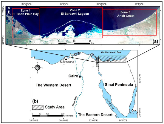
Figure 1.
Study area (a) overall; and (b) within Egypt.
The Mediterranean coastal plain of the Sinai Peninsula is covered with saltmarsh, fish farms, sand and sabkha deposits. It is devoid of vegetation cover. The study area was classified according to the geomorphology of the coast into three zones: Zone (I) located in the west of study area and includes the Tinah Plain Coast (TPC) which extends from the entrance of Suez Canal to Bardawil lake to the east, the land cover in its coastal zone is the El Mallaha Lagoon, muddy coastal plain, fish farms and the Sabkha wetland. Zone (II) includes El Bardawil lagoon which has a vulnerable sand barrier. The barrier contains three shallow inlets connecting the lake with the Mediterranean Sea. Zone (III) comprises the El Arish Valley. It is covered by sand dunes, sabkha and wadi (dry valley) deposits. The three zones are shown in Figure 2.
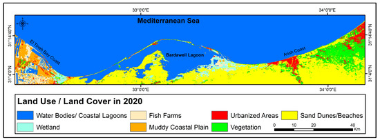
Figure 2.
Supervised classification of land use/cover of study area derived from 2020 Landsat-8.
A marine climate is the main driver for the coastal erosion/accretion process. Waves along the southern Mediterranean coast are a function of high-pressure weather systems [14]. Waves action is normal in summer and spring. The wave height reaches 1.20 m with an average of 40 cm. The Northwest (NW) is the dominant direction. The waves in winter are stronger, coming from three different directions N, NNW and NW. During storms, the wave height reaches 4.2 m [15,16].
2.2. Materials
Landsat images taken between 1990 and 2020 were the primary data source. Data were collected from multiple sensors including Landsat-5 (TM), Landsat-7 (ETM+) and the Landsat-8 (OLI). The USGS Earth Explorer website offers the satellite data to download in “GeoTIFF” format, as shown in Table 1. These Landsat datasets were radiometrically corrected to the surface reflectance (Level-2).

Table 1.
Landsat images used in this study.
2.3. Methods
Methods applied in this study were performed in three stages: (1) data collection and pre-processing of satellite imagery, including band combination, geometric and radiometric corrections, (2) applying spectral indices of NDWI and MNDWI for the automatic detection and extraction of coastlines, and (3) morphological analysis of coastal changes. Figure 3 is a flow chart of the methods used in the study.
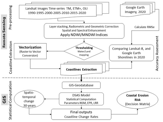
Figure 3.
Methodology.
2.3.1. Coastline Delineation
The NDWI is a water index that was created by McFeeters in 1996. It is a ratio between the high absorption of the NIR band and high reflectance of the green band in water bodies [7]. The NDWI can be used to differentiate a coastline from everything else. On the other hand, the MNDWI index uses short wavelength infrared (SWIR) and green bands to effectively map coastlines for most coasts including urbanized and vegetated coasts. The satellite images acquired for our study area used ERDAS Imagine using arithmetic operations in model builder to differentiate water/land using the thresholding method. NDWI was calculated using the following Equation (1):
where ρGreen is the green band, and ρNIR is the NIR band.
NDWI uses two bands to (1) maximize water reflectance in the visible green band, (2) minimize water reflectance in NIR, and (3) use the advantages of the high reflectance of vegetation and soil in the NIR [17]. Therefore, Landsat sensors that have these spectral bands (green and NIR) can only be used to calculate this index. The values of the NDWI range between 1- and +1. The positive values refer to water features and the negative values refer to the soil and vegetation.
Identification of water and land features is increasingly problematic as coasts become more urbanized [7]. MNDWI uses the MIR and green bands to increase the quality of results and reduce “noise” along urbanized coasts. MNDWI in Equation (2) [18]:
where ρMIR is the MIR band.
The calculation process in ERDAS Imagine v.2015 software of the NDWI/MNDWI water spectral indices used in this study is shown in Figure 4.
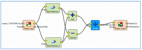
Figure 4.
ERDAS Imagine model maker interface used to calculate NDWI/MNDWI.
After the NDWI and MNDWI were applied, a threshold value was applied to map water bodies from other features using segmentation algorithms. Generally, the optimal threshold is often applied to extract water features from the NDWI/MNDWI spectral index results. The water feature is considered the pixel value equal to or higher than zero for most of the spectral indices. Because there are spatial and temporal variations from place to place over time, these differences could have an impact on the multispectral images. Therefore, the optimal threshold was selected and applied with respect to the water index values for each scene [19].
The use of spectral indices for water feature extraction needs a threshold to divide the image into two classes: water or land. This threshold is likely different with different land cover classes [20]. The OTSU algorithm is an optimal threshold used to maximize separation between two classes from the binary grey-scale image [21]. The OTSU algorithm has been used in several studies to identify and map water/land features from Landsat images [22].
The OTSU threshold algorithm was applied in this study to classify water/land classes. Pixel values equal to or higher than the OTSU threshold value refer to the water feature; other values represent different non-water features [22]. Applying the OTSU threshold values for coastline feature extraction from different spectral water indices is shown in Figure 5. Subsequently, ESRI ArcGIS Software was used to convert coastlines from raster-to-vector format based on the classified water body binary maps [23]; the extracted vector coastlines were stored in a GIS-geodatabase according to DSAS model validation, as shown in Figure 5c.
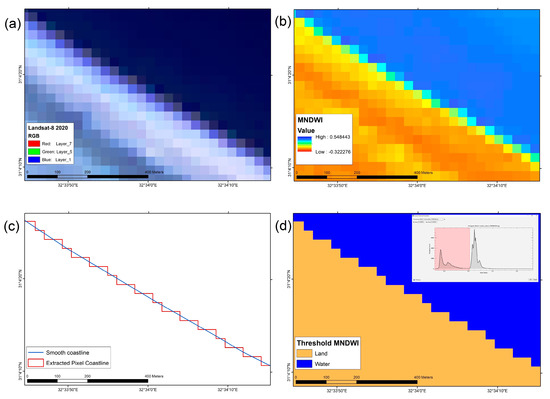
Figure 5.
Coastline auto-extraction. (a) Landsat-8 taken in 2020; (b) MNDWI values; (c) vector-based pixel and smooth extraction for coast; and (d) binary land/water thresholding.
Accuracy assessment of the extracted coastline from Landsat taken in 2020 was calculated using the root mean square error (RMSE), as mentioned. Calculations were made by comparing the spatial locations for both extracted (ext) and reference coastline. High-resolution GoogleEarth imagery acquired in 2020 was used to digitize the reference coastline.
RMSE was normalized to decrease the effects of the difference of ranges and values. Normalization of the RMSE (NMRSE) allows comparison between datasets. Values around zero refer to a good match between the data [24].
where refer to the distance between baseline and reference coastline at transect i, refer to distance from baseline to the extracted coastline at transect i, and n refers to the number of total transects.
whererefers to the average distances between the baseline and reference coastline for all transects used.
2.3.2. Uncertainty Estimation of the Extracted Coastlines
Coastline change analysis using satellite imagery can result in data errors or uncertainties which must be calculated and corrected. There are four uncertainties in data quality that are relevant to this study, as shown in Table 2. (1) Error of Pixel (Ep): this error varies based on the spatial resolution of images; (2) Orthorectification Error (Eg): this data error is inserted in the metadata file of any images. For this study, the RMSE of orthorectification was less than 0.5 pixels, which indicates a strong fit of image geometry. (3) Ideal Error Range (Ev): this error is related to the tidal regime range. Inaccurate results of coastline positions from MRS images along the tidal coastal zone can occur. Along the SMC, the dominant tidal regime does not exceed 0.40 m [14], which is considered insignificant for coastline displacement error. (4) Error of the coastline extraction (Ex): this error value can be calculated from the RMSE. Uncertainty of total error () can be estimated from the results from all previous data errors, as shown in Equation (5). The total calculated error data values in this study range from 39.9 m to 41.6 m. Annualized error (U) related to the coastline change rate at any given transect is shown in Equation (6).

Table 2.
Uncertainty assessment.
The calculated annual error for the period of study was 3.3 m/yr. The DSAS model requires the uncertainty error value as input to accurately calculate the coastline rate of change. The Confidence of End Point Rate (ECI) can be estimated using two coastline positions of the years used in the end point as calculated by Equation (7).
2.3.3. Coastline Change Analysis
The digital shoreline analysis system (DSAS) was created by the United State Geological Survey (USGS.) It can analyze coastal dynamics of shores, cliff retreat, erosion and perform predicative modeling [25]. The DSAS depends on creating transects that measure spacing between a baseline and historical coastlines. Rate of change statistics can be computed. In this study, 1976 transects were created perpendicular to the baseline with a spatial interval of 100 m.
Three spatial statistical approaches were used to assess the spatial temporal characteristics of coastline change along SCM: (1) End Point Rate (EPR), (2) Net Shore Movement (NSM), and (3) Linear Regression Rate (LRR). The NSM was measured for total distance between two coastline positions in two different periods. The End Point Rate (EPR) describes the patterns and trends of coastline change as main statistical parameters. EPR measures changes in coastline by dividing the movement of the coastline according to its current position. The LRR computes long-term variations of the coastline change rate. Spaces among transects were noted based on the coastline change pattern alongside the baseline and transects [26].
The rate of change during the study period (1990 to 2020) was computed by DSAS using multiple coastline vector data formats, as shown in Figure 6, Figure 7 and Figure 8. The End Point Rate of change was calculated using Equation (8).
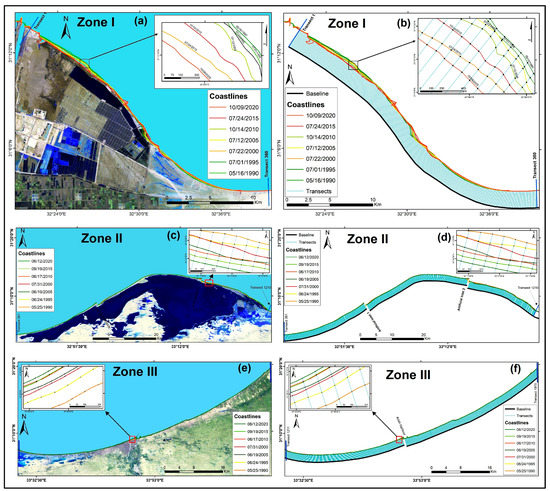
Figure 6.
The SMC between 1990 and 2020. (a) Tienah Plain Bay in 2020; (b) TPB Coastline and Transects at 100 m intervals; (c) the Bardaweil Coastal Barrier; (d) Bardaweil Coastline and Transects at 100 m intervals; (e) Arish Valley Coast; and (f) Arish Valley Coastline and Transects at 100 m intervals.
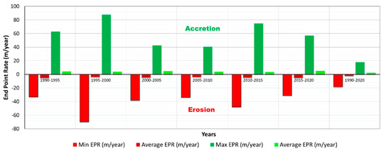
Figure 7.
Coastal change rates from 1990 to 2020.
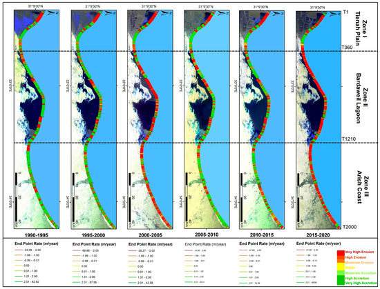
Figure 8.
EPR of coastline change between 1990 and 2020.
2.3.4. Classification of Shoreline Erosion
The statistical approaches of the DSAS model resulted in positive values (+) referring to the accretion process seaward, while negative values (-) refer to the retreat of shoreline landward. Erosion and accretion rates along the SMC were classified and mapped into seven categories according to the global classification of coastal erosion hazard and risk introduced by Natesan et al. [27], as presented in Table 3.

Table 3.
Hazard degree of coastline change rate.
3. Results
3.1. Rate of Coastline Change between 1990 and 2020
The 1976 transects of the SMC taken at 100 m intervals were used to assess morphological changes between 1990 and 2020 at 5-year intervals using EPR and LRR rates of change statistics. The analysis of the EPR and LRR rate of change between 1990 and 2020 showed no significant difference between them with the R2 value exceeding 0.99. Morphological changes of the SMC were determined using EPR rates which were calculated for six periods (1990 to 1995, 1995 to 2000, 2000 to 2005, 2005 to 2010, 2010 to 2015 and 2015 to 2020). The summarized spatial statistics for each intermediate period are shown in Table 4. Spatial variations of coastline change rates along SMC between 1990 and 2020 are presented in Figure 7.

Table 4.
Coastline change statistics between 1990 and 2020.
The overall analysis of the coastal erosion rates along the study area between 1990 and 2020 are shown in Figure 7 and Figure 8. They show that the SMC had an average retreat of 2.5 m/yr. over the 30-year period of study. The highest annual erosion rate was 5.2 m/yr. between 1990 and 1995. The lowest erosion rate was 3.9 m/yr. between 1995 and 2000. Coastal protective devices such as lagoon inlets, harbors and navigational entrance canals decreased erosion rates. The annual rate along the SMC coastline was 2.3 m/yr. between 1990 and 2020, while the lowest accretion rate was 3.9 m/yr. between 2010 and 2015. The annual accretion rate increased to 5.2 m/yr. from 2015 to 2020.
3.2. Assessment of Zonal Coastal Change
3.2.1. El Tienah Plain Coast (TPC)
The TPC is in the western part of the study area extending 36 km from the Suez Canal entrance to the Bardaweil lagoon. TPC occupies approximately 18% of the SMC and has 360 transects, as shown in Figure 9. The TPC has a highly vulnerable sand barrier at the Al Mallaha lagoon. Analysis of coastline change along the TPC between 1990 and 2020 indicates that the coastline has retreated 554.0 m with an average rate of 7.7 m/yr. The TPC has advanced 542.1 m with an average accretion rate of 4.5 m/yr. In this coastal zone, the lowest average annual coastline erosion was 8.2 m/yr. from 1990 to 1995. It increased to 11.9 m/yr. from 2010 to 2015, as shown in Table 4.

Figure 9.
Land Use/Land Cover Changes along the El Tienah Plain. (a) 1990 Landsat-5; (b) 2000 Landsat-7; (c) 2010 Landsat-5; and (d) 2020 Landsat-8.
Between 1990 and 2020, several coastal protection structures were built in this zone. Landsat images taken between 1995 and 2000 show barriers at Port Said including two jetties and a seawall. The seawall reduced coastline erosion in some sections, but it caused erosion to the adjacent area. Currents moved disassembled sandy soil from west to east causing the erosion [15].
Between 2010 and 2015, the coastline retreated 228.7 m at an average annual rate of 11.9 m/yr. It was the highest average annual rate for the SMC during the study period. A natural inlet formed in the Mallaha Coastal Barrier, as well as an underwater groin southward. Between 2015 and 2020, the eastern jetty of the Suez Canal entrance was extended to protect a larger area as well as two artificial inlets which were constructed along the Al Mallaha Lagoon sand barrier. Both are protected with two parallel jetties to avoid instability of bank erosion and sedimentation, as shown in Figure 10.
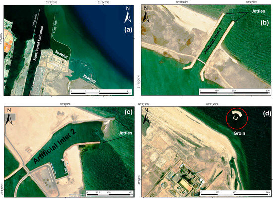
Figure 10.
Coastal protection devices along the El Tienah Plain. (a) Suez Canal Entrance Jetties; (b) Jetties of Artificial Inlet-1; (c) Jetties of Artificial Inlet-2; and (d) Onshore Groin.
A Coastal Erosion Decision Matrix (CEDM) was created for each zone according to the severity of coastal processes erosion/accretion. Each zone was divided into groups of sub-regions and evaluated according to the EPR results. Figure 11 shows the CEDM for the El Tienah coastal plain zone. Six sub-regions were identified along the SMC coast (A, B, C, D, E and F). Sub-regions A, B, and D eroded. Section A, which extends 8.7 km downward of the long current direction, had an annualized average erosion rate of 11.4 m/yr. This section was impacted by anthropogenic factors, including jetties and seawalls at the Suez Canal entrance and land use activities in the El Tienah coastal plain. Section B had an average erosion annual rate of 3.4 m/yr. for a distance 2.1 km downward. Section B was impacted by an artificial inlet-1 coastal jetty. Section D is located adjacent to the onshore groin downward. It has also had a high erosion rate (2.4 m/yr.).
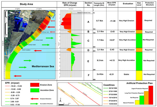
Figure 11.
Coastal erosion management matrix for the El Tienah Plain Zone between 1990 and 2020.
Sections C and E had an annual accretion rate of 5.6 m/year and 4.1 m/year, respectively. Section F, which is located downward of the TPC, is stable with an average annual accretion of 30 cm/year. According to the CEDM, sections C, E, and F are “stable” regions along the TPC.
3.2.2. The Bardaweil Lagoon Barrier Coast (BLBC)
The BLBC represents the central zone of the SMC extending 87 km along 845 transects and covering 43% of SMC. The BLBC is less than 1,000 m from the sea. It separates the El Bardawil lagoon from the Mediterranean Sea. There are three small inlets that connect the lagoon with the sea; two inlets are artificial (Numbers 1, 2) and the third inlet, El Zaranek, is natural, as shown in Figure 12.
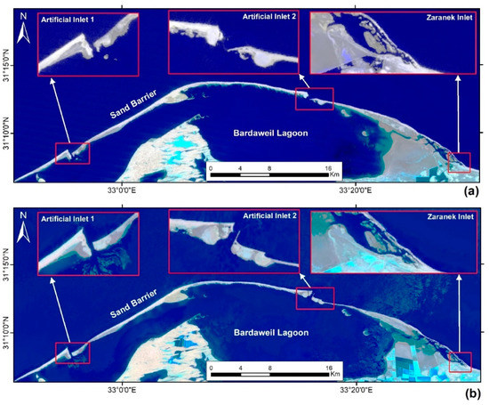
Figure 12.
The Bardaweil Lagoon Barrier Coast (a) 1990 Landsat-TM (b) 2020 Landsat-OLI TIRS.
Siltation is controlled by marine factors along these inlets. Siltation causes problems due to the hydraulic connection of the lagoon with the sea. Since 1991, jetties have been built along the entrance of the artificial inlets (1) and (2). Although jetties and other coastal structures have helped to maintain the navigational canals of these inlets, they have led to coastal erosion and extreme forwarding of the coast [28]. The BLBC coastline retreated during the study period 284.7 m with an annual average erosion rate of 2.1 m/yr. It also advanced over the same period 451.6 m with an average annual accretion rate of 2.0 m/yr. The percentage of erosional area represents 65%, while the accretion area represents 30% of BLBC.
The average annual erosion rate along BLBC decreased from 5.4 m/year between 1990 and 1995 to 3.3 m/year in the period 2005 to 2010. Erosion increased to 5.4 m/yr. between 2015 and 2020. The higher erosion is related to the jetties at the entrances of the inlets which caused erosion zones’ eastward direction. The average annual accretion rate along BLBC ranged between 4.6 m/yr. for the period 1990 to 1990 and increased to 45.4 m/yr. for the period 2015 to 2020 because of sediment accumulations behind the jetties’ upward alongshore current, as shown in Figure 13.
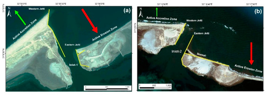
Figure 13.
Coastal Structure along the Bardaweil Artificial Inlets (a) Inlet-1 (b) Inlet-2. The green arrow refers to the accretion zone behind the western Jetty, while the red arrow refers to active erosion zone downward.
The CEDM identified seven sub-regions along the BLBC zone based on EPR coastline erosion/accretion rates between 1990 and 2020. Two sub-regions, C and F, located eastward of the entrance of artificial inlets at 11.7 km., had erosional rates of 3.9 and 4.0 (m/yr.), respectively, which require protection, as shown in Figure 14.
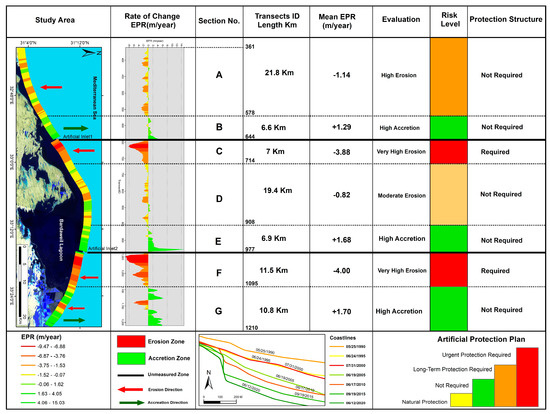
Figure 14.
Coastal erosion management matrix along the Bardaweil Lagoon between 1990 and 2020.
Three coastal accretion sections, B, E, and G, with a length of 6.6, 6.9, and 10.8 km., respectively, had annual average accretion rates of 1.3, 1.7 and 1.7 m/yr., respectively. Both B and E sections occur along the western sides of the inlet jetties. The jetties impact longshore sediment transportation eastward. Sections A and D had average annual erosional rates of 1.1 and 0.8 m/yr., respectively. These sections are located along the coastal lagoon sand barrier which is naturally protected with sand dunes and beach sand.
3.2.3. Arish Valley Coast (AVC)
The AVC has 766 transects and represents 40% of the SMC. The AVC extends from El Zaranek to the Egyptian national eastern border. Overall analysis of the AVC coastline changes between 1990 and 2020 shows an average annual coastal erosion rate of 1.0 m/yr. and an accretion rate of 1.1 m/yr. The coastline retreated landward a distance of 52.1 m and advanced seaward 367.4 m during the study period. The spatial/temporal analysis of coastline changes along AVC showed an average annual erosion rate of 2.8 m/yr. between 1990 and 1995 and 3.0 m/yr. between 2000 and 2005. To mitigate severe coastal erosion along the western side of Al Arish Harbor, the Shore Protection Agency (SPA) built seven short groins in 2005 to protect El-Arish city from waves and the coastal erosion process. The SPA constructed 11 more short groins later. Between 2007 and 2008, another five groins were added [29].
The beaches in the west of El Arish harbor advanced because of harbor jetties in the interruption of the dominant longshore current eastward. Although the west side of the Arish port reversed to an accretion zone, new severe erosion occurred eastward.
To conserve and mitigate the coast from severe erosion, 13 short groins were installed between 1988 and 1990, as well as beach renourishment projects. From 1988 to 1989, the SPA built a series of five groins [29]. From 2015 to 2020, the average annual erosion rate increased to 3.3 m/yr. due to the groins.
The accretion annual rate was 3.0 m/yr. from 1990 to 1995, but it increased to 3.3 m/year from 2010 to 2015 in response to the advancing coastline behind the western harbor jetty. The accretion rate was as high as 2.8 m/yr. from 2015 to 2020, as shown in Figure 15.

Figure 15.
Coastal protection structures along the Arish Coast. (a) Al Arish Beach High Short Groins; (b) Al Arish Port Jetties and Short Groins.
The CRDM identified eight sub-regions of coastline erosion/accretion in the Arish Valley between 1990 and 2020. There were three erosion sections, A, E, and G, with lengths of 14 km., 9.8 km. and 4.7 km., respectively. All these sections were produced down drift of the protected area. Section A is a moderate coastal erosion section with an annual average loss of 0.9 m/yr. This section does not require immediate protection. Section E is a high erosion zone due to the coastal protection system for the city of Al Arish. The average annual erosion rate was 1.4 m/year from 1990 to 2020, as shown in Figure 16.
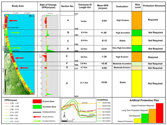
Figure 16.
Coastal erosion management matrix along the Arish Valley Coast between 1990 and 2020.
Section G had a moderate erosion rate of 0.5 m/yr. Two accretion sections, B and D, had accretion rates of 5.4 km and 5.9 km, respectively. They were formed from the sediments trapped behind the jetties’ downward alongshore current. The annual average accretion rate in these sections was 1.4 m/year for section B and 2.8 m/year for section D. Sections C and H were the most stable sub-regions with practically no change.
4. Discussion and Conclusions
The results of this study show that the rate of change along the SMC is uneven with some areas accreting while others were eroded during the study period. The SMC retreated landward 554 m with an annual average EPR rate of 2.5 m/year. Sixty percent of the coastline eroded. The SMC advanced seaward 542 m with an annual average EPR rate of 2.3 m/yr. 40% of the SMC accreted.
Assessment of the SMC was performed for three zones: (1) the El Tienah Coastal Plain (TCP), (2) the Bardaweil Lagoon Barrier Coast, and (3) the Al Arish Valley Coast. The TCP had the highest average annual erosion rate of 7.7 m/yr. Hard structures such as jetties, seawalls and groins were built to mitigate coastal erosion in this zone. However, trend analysis of coastal erosion along TCP increased from 8.2 m/year from 1990 to 1995 to 9.5 m/yr. between 2015 and 2020. CEDM identified three coastal erosion sections requiring urgent protection from erosion. The BLBC zone had a lower average annual retreat and advance rates were 2.1 m/yr. and 2.0 m/yr. between 1990 and 2020.
The SPA protected entrances of artificial inlets with hard-structure jetties to save the banks from erosion instability. The average annual rate from 1990 to 1995 was 5.4 m/year, which increased to 5.4 m/yr. between 2015 and 2020. Along BLBC, the CEDM determined that two sections needed urgent protection close to the artificial inlets for 18.5 km. eastward.
The AVC has the lowest erosion/accretion rates of the SMC with an average annual erosion rate of 1.0 m/year, while the accretion rate was 1.1 m/yr. The SPA installed two long jetties to protect the Arish Harbor from wave and currents. There were 23 short groins on the western side of Arish Harbor and 13 short groins on the eastern side of the harbor to reduce erosion in the city; however, the coastal protection devices caused erosion rates of 3.3 m/yr. east of the city of Arish.
All low-lying deltas are subject to increasing pressure to combat sea level rise, increased number and severity of storms and man-made structures such as groins. All contribute to erosion and accretion. Egypt’s delta is particularly venerable to coastal erosion since the Aswan High Dam prevents silt from replenishing the coastline. Therefore, it is critical that the Mediterranean coastline be constantly monitored. The techniques present in this research will allow this to be achieved at a reasonable cost.
Author Contributions
Conceptualization, K.D.; methodology, K.D.; software, K.D.; validation, K.D., S.S.; formal analysis, K.D.; investigation, K.D.; resources, K.D.; data curation, K.D.; writing—original draft preparation, K.D.; writing—review and editing, S.S.; visualization, K.D.; supervision, S.S. All authors have read and agreed to the published version of the manuscript.
Funding
This research received no external funding.
Data Availability Statement
Imagery used in this study are available for free from the USGS Earth Explorer website (www@USGS Earth Explorer.gov).
Conflicts of Interest
The authors declare no conflict of interest.
References
- Wang, X.; Liu, Y.; Ling, F.; Liu, Y.; Fang, F. Spatial-Temporal Change Detection of Ningbo Coastline Using Landsat Time-Series Images during 1976–2015. ISPRS Int. J. Geo-Inf. 2017, 6, 68. [Google Scholar] [CrossRef]
- Kermani, S.; Boutiba, M.; Guendouz, M.; Guettouche, M.; Khalfan, D. Detection and analysis of shoreline changes using geospatial tools and automatic computation: Case of Jijelian sandy coast (East Algeria). Ocean Coast. Manag. 2016, 132, 46–58. [Google Scholar] [CrossRef]
- Zhang, Y. Coastal environmental monitoring using remotely sensed data and GIS techniques in the Modern Yellow River delta. Env. Monit Assess 2011, 179, 15–29. [Google Scholar] [CrossRef] [PubMed]
- Yasir, M.; Sheng, H.; Fan, H.; Nazir, S.; Niang, A.; Salauddin, M.; Khan, S. Automatic Coastline Extraction and Changes Analysis Using Remote Sensing and GIS Technology. IEEE Access 2020, 8, 180156–180170. [Google Scholar] [CrossRef]
- Pardo-Pascual, J.; Almonacid-Caballer, J.; Ruiz, L.; Palomar-Vázquez, J. Automatic extraction of shorelines from Landsat TM and ETM+ multi-temporal images with subpixel precision. Remote Sens. Environ. 2012, 123, 1–11. [Google Scholar] [CrossRef]
- Toure, S.; Diop, O.; Kpalma, K.; Maiga, A. Shoreline Detection using Optical Remote Sensing: A Review. ISPRS Int. J. Geo-Inf. 2019, 8, 75. [Google Scholar] [CrossRef]
- McFeeters, S. The use of the Normalized Difference Water Index (NDWI) in the delineation of open water features. Int. J. Remote Sens. 1996, 17, 1425. [Google Scholar] [CrossRef]
- Jain, S.; Singh, R.; Jain, M.; Lohani, A. Delineation of Flood-Prone Areas Using Remote Sensing Techniques. Water Resour. Manag. 2005, 19, 333–347. [Google Scholar] [CrossRef]
- Hui, F.; Xu, B.; Huang, H.; Yu, Q.; Gong, P. Modelling spatial-temporal change of Poyang Lake using Multitemporal Landsat imagery. Int. J. Remote Sens. 2008, 29, 5767–5784. [Google Scholar] [CrossRef]
- Xu, H. Modification of normalized difference water index (NDWI) to enhance open water features in remotely sensed imagery. Int. J. Remote Sens. 2006, 27, 3025–3033. [Google Scholar] [CrossRef]
- Frihy, O.; Lotfy, M. Shoreline changes and beach-sand sorting along the northern Sinai coast of Egypt. Geo-Mar. Letters. 1997, 17, 140–146. [Google Scholar] [CrossRef]
- Frihy, O.; Badr, A.; Selim, M.; El Sayed, W. Environmental Impacts of El Arish Power Plant on the Mediterranean Coast of Sinai, Egypt. Environ. Geology. 2002, 42, 604–611. [Google Scholar]
- Azab, M.; Noor, A. Change Detection of the North Sinai Coast by Using Remote Sensing and Geographic Information System. Geogr. Technica. 2007, 2003, 2–10. [Google Scholar]
- El Banna, M.; Herher, M. Detecting temporal shoreline changes and erosion/accretion rates, using remote sensing, and their associated sediment characteristics along the coast of North Sinai, Egypt. J. Environ. Geol. 2009, 8, 1419–1427. [Google Scholar] [CrossRef]
- Nassar, K.; Mahmod, W.; Fath, H.; Masria, A.; Nadaoka, K.; Negm, A. Shoreline change detection using DSAS technique: Case of North Sinai coast, Egypt. Mar. Georesources Geotechnol. 2019, 37, 81–95. [Google Scholar] [CrossRef]
- Nassar, K.; Fath, H.; Mahmod, W.E.; Masria, A.; Nadaoka, K.; Negm, A. Automatic detection of shoreline change: Case of North Sinai coast, Egypt. J. Coast. Conserv. 2018, 22, 1057–1083. [Google Scholar] [CrossRef]
- Li, W.; Du, Z.; Ling, F.; Zhou, D.; Wang, H.; Gui, Y.; Sun, B.; Zhang, X. A Comparison of Land Surface Water Mapping Using the Normalized Difference Water Index from TM, ETM+ and ALI. Remote Sens. 2013, 5, 5530–5549. [Google Scholar] [CrossRef]
- Rokni, K.; Ahmad, A.; Selamat, A.; Hazini, S. Water feature extraction and change detection using multitemporal Landsat imagery. Remote Sens. 2014, 6, 4173–4189. [Google Scholar] [CrossRef]
- Ji, L.; Zhang, L.; Wylie, B. Analysis of dynamic thresholds for the normalized difference water index. Photogramm. Eng. Remote Sens. 2009, 75, 1307–1317. [Google Scholar] [CrossRef]
- Tang, W.; Zhao, C.; Lin, J.; Jiao, C.; Zheng, G.; Zhu, J.; Pan, X.; Han, X. Improved Spectral Water Index Combined with Otsu Algorithm to Extract Muddy Coastline Data. Water 2022, 14, 855. [Google Scholar] [CrossRef]
- Zhang, X.; Wang, W.; Yang, C.; Yan, W.; Dai, Y.; Xu, P.; Zhu, C. Historical Coastline Spatial-temporal Evolution Analysis in Jiangsu Coastal Area During the Past 1000 Years. Sci. Geogr. Sin. 2014, 34, 344–351. [Google Scholar]
- Zhang, J.; Lai, Z.; Sun, J. Coastline extraction of remote sensing image by combining Otsu, regional growth method with morphology. Bull. Surv. Mapp. 2020, 10, 89–92. [Google Scholar]
- Darwish, K.; Smith, S.; Torab, M.; Monsef, H.; Hussein, O. Geomorphological changes along the Nile Delta coastline between 1945 and 2015 detected using satellite remote sensing and GIS. J. Coast. Res. 2017, 33, 786–794. [Google Scholar] [CrossRef]
- Atiquzzaman, M.; Kandasamy, J. Prediction of hydrological time-series using extreme learning machine. J. Hydroinf. 2015, 18, 345–353. [Google Scholar] [CrossRef]
- Oyedotun, T. Shoreline Geometry: DSAS as a Tool for Historical Trend Analysis. Geomorphol Technol. 2014, 3, 1–12. [Google Scholar]
- Das, S.; Sajan, B.; Ojha, C.; Soren, S. Shoreline change behavior study of Jambudwip island of Indian Sundarban using DSAS model. Egypt. J. Remote Sens. Space Sci. 2021, 24, 961–970. [Google Scholar]
- Natesan, U.; Parthasarathy, A.; Vishnunath, R.; Kumar, G.; Ferer, V. Monitoring long term shoreline changes along Tamil Nadu, India using geospatial techniques. Aquat. Procedia 2015, 4, 325–332. [Google Scholar] [CrossRef]
- Frihy, O.E.; Fanos, A.M.; Khafagy, A.A.; Komar, P.D. Patterns of nearshore sediment transport along the Nile Delta, Egypt. Coast. Eng. 1991, 15, 409–429. [Google Scholar] [CrossRef]
- Abu Zed, A.A.; Soliman, M.R.; Yassin, A.A. Evaluation of using satellite image in detecting long term shoreline change along El-Arish coastal zone, Egypt. Alex. Eng. J. 2018, 57, 2687–2702. [Google Scholar] [CrossRef]
Disclaimer/Publisher’s Note: The statements, opinions and data contained in all publications are solely those of the individual author(s) and contributor(s) and not of MDPI and/or the editor(s). MDPI and/or the editor(s) disclaim responsibility for any injury to people or property resulting from any ideas, methods, instructions or products referred to in the content. |
© 2023 by the authors. Licensee MDPI, Basel, Switzerland. This article is an open access article distributed under the terms and conditions of the Creative Commons Attribution (CC BY) license (https://creativecommons.org/licenses/by/4.0/).