Abstract
Non-uniformity in the response of spectral image elements is an inevitable phenomenon in hyperspectral imaging, which mainly manifests itself as the presence of band noise in the acquired hyperspectral data. This problem is prominent in the infrared band owing to the detector material, operating environment, and other factors. Non-uniformity is an important factor that can affect the quality of the hyperspectral data, which has a serious impact on both data analysis and applications and requires corrections via technical means wherever possible. This paper proposes a novel target-based non-uniformity self-correction method for infrared push-broom hyperspectral images. The Mars Mineralogical Spectrometer (MMS) onboard the Tianwen-1 orbiter was used as the research and application object. The model is constructed and applied to the target scene characteristics and detection patterns of Mars remote sensing exploration, which are combined with the causes of noise generation in the infrared spectral image bands. The design of the MMS dual-channel Visible-Near-Infrared (V-NIR) and Near-Mid-Infrared (N-MIR) co-field of view co-target detection and laboratory calibration data for the V-NIR spectral band can achieve non-uniformity corrections (NUCs). Therefore, for the MMS in-orbit Mars exploration mission, the method selected spectral data (920–1055 nm) characterized by a reduced atmospheric influence to iteratively obtain the homogeneous region, which was used to calculate the non-uniformity correction factor for the N-MIR spectral band. This method was compared, validated, and evaluated with other conventional methods using both laboratory and in-orbit hyperspectral data. The results showed that the experimental data corrections were comparable to laboratory calibrations, with a maximum relative deviation of <2.6%. These results prove that our method not only provides an excellent non-uniformity correction, but also ensures spectral fidelity. It can thus be used as a non-uniformity correction process for the MMS and similar hyperspectral imagers.
1. Introduction
The two-dimensional (2-D) focal plane of a push-broom infrared hyperspectral imager is used in one dimension to receive spectral information and in the other dimension for line-array push-broom imaging. Different detection units acquire the radiation signals in the same band at different spatial locations in the line-array target. Inconsistencies in the response between different elements of the 2-D focal plane are inevitable with existing detector materials and process technologies [1,2]. At the same time, such non-uniformity is often closely related to the instrument operating environment, which can lead to more complex NUCs [3,4]. The presence of non-uniformity simultaneously reduces the imaging quality and spectral accuracy of hyperspectral images, which have a serious impact on information extraction and target identification. Effective NUCs must be realized to ensure effective scientific output.
Prior to launch, NUC factors for the push-broom hyperspectral imager had to be obtained via a laboratory calibration. After orbit, three main methods can be used to further correct for possible changes in the uniformity of the detector (when the correction coefficients obtained by ground calibration do not conform to the correction requirements): spectral filter-based methods [5,6,7], full variational and improved algorithms [8,9,10,11], and spatial domain information statistics-based methods and improved algorithms [12,13,14,15,16]. Methods based on spectral filtering mainly include the joint frequency domain, space domain filtering, and wavelet transform filtering. However, a loss of image detail and image blurring will occur while filtering due to damage to the overall structure of the image; furthermore, this method cannot determine the frequency of noise. Various algorithms based on full variance can be developed by constructing an energy generalization equation with constraints; however, the parameters of the constraints are not easily selectable, especially when characterized by noise. Methods based on spatial domain information statistics mainly include histogram matching, moment matching, and their improvement algorithms. These methods directly employ the original information in the image data, which is easy to use and portable. However, reasonable assumptions concerning the reference value not affected by non-uniformity directly determine optimal or poor denoising qualities. As for the use of popular machine learning methods, their usability is greatly reduced by the lack of real data. It does not work for the solution of practical NUC problems.
This paper proposes an NUC method based on the bright and dark regions of an image via analyses of spectral imaging detection modes and instrument characteristics, although this is not the first time this idea has been proposed (for example, Hu et al. used histogram statistics to obtain bright and dark regions for NUCs [17], and Zhou et al. used two phases (training and application) for spectral calibration using indirect mapping [18]). Specifically, we perform a novel selection of bright and dark regions based on image segmentation from the simultaneous images that are least affected by non-uniformity, as opposed to various previous methods that work only on the uncorrected image directly. This successfully decreases the amount of mistakes generated by prior methods that made assumptions on the uncorrected image based on the statistical idea of spatial domain information and does not require data from a laboratory for training. Additionally, the algorithm is simple and clear to operate. Our method uses Mars Mineralogical Spectrometer (MMS) data, from imaging scenes on the Martian surface while in orbit, and hyperspectral data, acquired by laboratory calibrations, to perform NUC experiments and application validations. This achieved satisfactory calibration results. This paper aims to yield more effective NUCs for the MMS and provide practical correction methods and technical procedures for NUCs with similar payload data.
2. Materials and Methods
2.1. MMS Data
Rocks and sediments on the surface record the evolutionary history of Mars, while the mineral composition and structural features of Martian rocks record rock formation conditions and history. Hyperspectral remote sensing surveys have played a major role in the identification, distribution, and characterization of typical mineral types on the Martian surface [19,20,21]. The MMS (Figure 1) is a Tianwen-1 orbiter science payload that acquires spectral images of the visible to infrared spectral bands on the Martian surface in a large elliptical orbit. At periapsis, the orbital altitude will reach a minimum of 265 km, an altitude of less than 800 km, and the effective detection time per orbit will be approximately 26 min. In order to enable dual-channel spectral imaging detection of the same object in the V-NIR and N-MIR spectral bands, the MMS comprises of a Visible-Near-Infrared (V-NIR) module and a Near-Mid-Infrared (N-MIR) module, both of which have the same field of view [22,23,24,25]. The V-NIR module uses a charge-coupled device (CCD) array detector (512 columns × 320 rows) to acquire spectral images from 379–1076 nm, while the N-MIR module uses a mercury–cadmium–telluride focal plane array (MCT FPA) (512 columns × 255 rows) to acquire spectral information from 1033 to 3425 nm. Both channels were designed with an instantaneous field of view (IFOV) of 0.5 mrad and a field of view (FOV) of 12°.
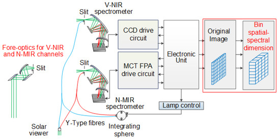
Figure 1.
Schematic diagram of the Mars Mineralogical Spectrometer instrument.
The data downlink limitations and spectral characteristics of different mineral types are considered when imaging the surface of Mars at the MMS nadir observation site. The scientific data can be downlinked as 2 × 2, 4 × 4, 8 × 8, and 16 × 16, among others, to obtain space-continuous 208-unit spectral sounding, space-continuous 104-unit spectral sounding, space-continuous 52-unit spectral sounding, and space-continuous 26-unit spectral sounding. Furthermore, the spectral dimension can include both hyperspectral (576-band) and multispectral (72-band) mode options [23]. As a result, this allows the MMS to have more complex non-uniform noise than conventional hyperspectral imagers.
2.2. N-MIR Spectrum Non-Uniformity
As described in Section 2.1, the MMS operates in the mode of returning data after binning multiple image elements and bands due to the limitation of data downlink bandwidth. At the detector level, the data in the MMS N-MIR spectral band have residual NUC errors from three main sources. First, when the operating environment is beyond the environment range of the instrument, the NUC coefficients measured before launch cannot be used. Second, after long-term work, errors are present due to aging image element response changes. The last point is that the on-chip blind element repair fails due to the floating variation of some blind elements of the MCT detector in the N-MIR module, and it is not possible to repair all blind element image values before the image elements are binned, which causes abnormal image element values.
The response of a well-performing imaging spectrometer is generally linear. In general, the relationship between the DN value of the image element and the radiance of the MMS output can be represented by a linear model:
where is the value of the MMS image element before binning; , , and are the column number, row number, and band number of the image element, respectively; is the gain; is the incident radiance; and is the bias (or dark background). The DN value of the image element after binning can be expressed as:
where is the pixel value of the MMS after binning; , and are the number of columns, rows, and bands of the bound, respectively (generally ); and , , and represent the column, row, and band serial numbers after binning, respectively. From the above formula, after the image element is bound, the radiance still has a linear relationship with the DN value.
The NUC factor can be obtained through radiometric calibration of a reference source before launch, such as an integrating sphere or a blackbody. The relationship between the radiometric calibration coefficients of the binned mode and un-binned mode can be approximated as:
where and are the gain and dark background after binning, respectively. The relationship between the binned pixel value and the radiance can be simplified and expressed as
where is the radiance corresponding to the image element after it is bound.
From the explanation above, it seems that working outside the instrument’s typical operating environment, image element aging, and image element blindness caused by an optical or electronic system defect can all affect the gain and dark background of binned pixels containing anomalous pixels. This will result in non-uniformity correction coefficients before launch not demonstrating the expected effects; the MMS data appear as strip noise, as shown in Figure 2.
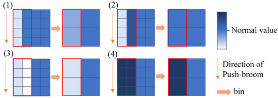
Figure 2.
Four typical cases of MMS image element binning. All these phenomena indicate problems where blind elements cannot be removed directly by the calibration factors obtained before launch.
2.3. Methods
The N-MIR spectral band data of the MMS can only be accurately corrected for non-uniformity by obtaining the correction coefficients. Although the NUC model is simple, the required solution parameters are only gain and bias, and there are increased difficulties in the absence of valid reference data. Based on laboratory calibration, each pixel from the same radiation source detector should have the same response. In actual imaging, if relatively bright and dark uniform areas can be obtained, a two-point correction can be used to perform enhanced NUCs. We can obtain the assumed prerequisites by analyzing the imaging characteristics of the experimental data from the MMS parking orbit. As shown in Figure 3, the MMS is on a large elliptical orbit, using spectral imaging data bands that span multiple latitudes. In the one-track data, as the dimensionality transforms from high to low, the column direction radiance value has notable high and low points; each spectrum segment has a regional difference in bright and dark areas from high to low latitudes. Based on this, the NUC sensor can obtain more objective and accurate correction coefficients that are similar to laboratory corrections. To combine the characteristics of the MMS, we formulated a set of technical procedures to correct the non-uniformity of the MMS N-MIR spectrum data, as shown in Figure 3.
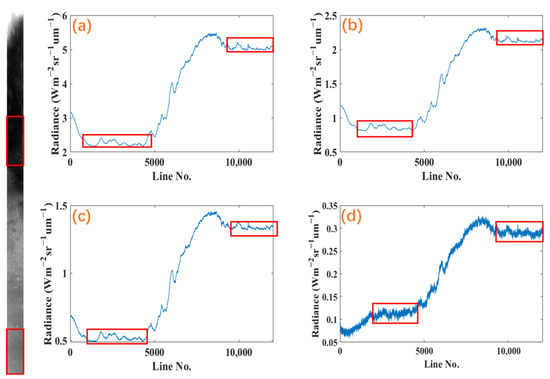
Figure 3.
A complete push-broom detection example (left). Radiance trends of different bands. The center wavelengths are (a) 1656.5 nm, (b) 2140.8 nm, (c) 2433.7 nm, and (d) 3307.2 nm. The red boxes show that there are bright and dark regions in various bands (right).
As shown in Figure 4, the NUC technique based on uniform regions mainly includes the following processes: dark background removal, V-NIR spectral band correction, uniform bright and dark region selection, and N-MIR spectral band NUC coefficient calculation. First, the dark background was removed from the MMS spectral data. The original NUC coefficient was then used to correct V-NIR spectral band non-uniformity to obtain V-NIR spectral data without strip noise. Next, the V-NIR spectral data were used as a reference to select the bright and dark uniform regions with uniform radiation. Finally, the uniform region was used as a reference to calculate the NUCs for the N-MIR spectral band coefficients. Each process is shown in Figure 4.
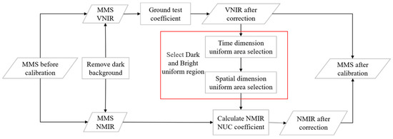
Figure 4.
Non-uniformity corrections process based on bright and dark uniform regions.
2.3.1. Dark Background Removal
In the N-MIR spectral band, the dark background derives from the detector’s dark current and internal instrument background radiation contributions. The MMS has a dark background monitoring area, which enables estimations of the dark background for each image per image element per frame [23]. The dark background value estimated from the dark background monitoring area was used for dark background removal calculations.
2.3.2. V-NIR Spectral Laboratory Coefficient NUC
Non-uniformity mainly includes inconsistent image element response caused by the detector process and vignetting caused by optical components. Generally, the response differences between the CCD detector elements used in the V-NIR band are small. Vignetting has a clear regularity such that we can easily correct non-uniformity. Therefore, V-NIR spectral non-uniformity correction can be completed using the laboratory non-uniformity correction coefficient under the same operating environment. Equation (3) can be used to compute the V-NIR spectral NUC.
2.3.3. Bright and Dark Uniform Region Selection
The presence of enhanced noise in the MMS N-MIR channel can affect uniform region selection. We assumed that the MMS V-NIR module uses a CCD array detector to complete spectral image acquisition. The nature of the CCD detector and V-NIR’s high signal-to-noise ratio, with a non-uniformity error of <1.5%, makes its streak noise negligible. Considering the existence of the Martian atmosphere, aerosols have a large impact on visible light. Therefore, we used the NIR spectrum of the V-NIR channel to select uniform bright and dark regions. The process is shown in Figure 5.
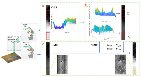
Figure 5.
MMS uniform region selection and correction flow chart. (a) Initial V-NIR selection of a uniform region in the time dimension, (b) further V-NIR selection of the uniform region in the spatial dimension, and (c) the N-MIR spectral band for the NUC.
The initial bright and dark uniform regions were first obtained through screening in the time dimension. As shown in the MMS image in Figure 6, we first merged the near-infrared (920–1055 nm) spectral dimension, which was followed by accumulation of the row direction to obtain a column mean . We set the sliding window size C to 2000 and the step size n to 100 lines. For each window , C column mean data were obtained. The window center position was assumed to be . The mean value and variance were obtained in each window. The mean value indicates the level of the value within the window. The smaller the variance, the more uniform the distribution of the values of the random variables, with reduced variability. These values are calculated as follows:
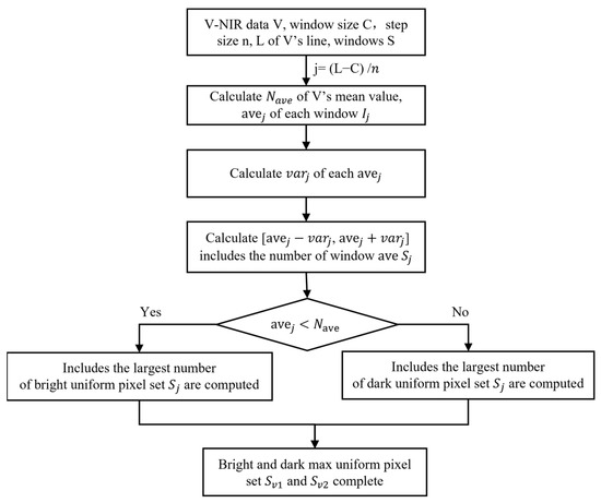
Figure 6.
Flow chart of the proposed method. and denote the set of the most uniform image windows, , that satisfy the condition.
The final bright and dark uniform regions were then determined via spatial segmentation. After obtaining the V-NIR data initially selected as a homogeneous image element set, features (i.e., shadows and borders) still existed in the image element set that were inconsistent with the background variation due to random distribution. Therefore, the initially selected bright and dark regions were segmented to remove the numerically limited outlier patches to obtain more desirable uniform regions. Region segmentation can be performed using more general threshold segmentation, more complex seed-filling gradient segmentation, or several other segmentation methods. Threshold-based segmentation is generally suitable when outlier image elements are characterized by a random distribution, while seed-filling gradient segmentation is suitable when the number of image rows is small and the outlier points form small-scale patches. For the best MMS approach in terms of Mars imaging features, we focused on the iterative thresholding segmentation algorithm.
The imaging data were transformed into a two-dimensional spatial image by first merging the spectral dimensions. For example, we used a modified iterative operation to find the upper boundary of a bright uniform region that distinguishes outlier patches by setting the initial threshold T0, which is usually the global grey scale average. Dividing the image into two parts according to the threshold T0, m0 and m1 are the average of the elements of the two parts of the image. The new value is obtained using the following calculation:
Subsequently, we set T0 = and repeated the above steps until the difference between the threshold value of the iteration and the previous iteration was less than 10−4. The final result, T1, is the upper boundary of the desired bright uniform region. The iterative formula for the lower boundary is:
Above, the set of image elements between the threshold T1 and T2 is the ideal bright uniform region. The calculation of the bright uniform region is shown in Figure 7. The ideal dark uniform region is calculated in the same way. Finally, the ideal set of bright and dark uniform regions, and , is obtained.
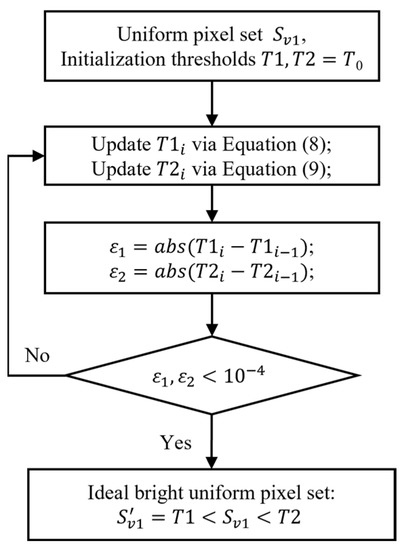
Figure 7.
Flow chart detailing how to obtain the ideal bright uniform region.
2.3.4. Calculation of NUC in the N-MIR Spectral Band
The image positions of the N-MIR channels and are the regional image sets and obtained from the V-NIR channels. To perform an accurate NUC for the hyperspectral data in the N-MIR band of the MMS, the correction coefficients and in Equation (5) must first be obtained.
In the bright region, we obtained the following:
In the dark region, we obtained the following:
where and are the values in the bright and dark regions in band k, respectively, and and are the median values of the column in the bright and dark regions in the K band. The NUC coefficient of each pixel was calculated as follows:
The N-MIR spectra NUC was completed using and to obtain the correction data :
3. Results and Discussion
3.1. Data and Evaluation Standards
The data used in this study were multispectral mode imaging data (19 spectral bands from V-NIR and 52 spectral bands from N-MIR selectively acquired for minerals) obtained by the MMS on 2 April 2021 from 63°–21° N on the surface of Mars. The vertical ground distance from nadir observation was 280–800 km and the spatial resolution was approximately 283–809 m/pixel. The size of the experimental data was 12,033 pixels × 207 pixels × 71 bands.
Ground truth is not available to evaluate the effectiveness of the method before performing NUCs. Therefore, two simulations were conducted in this study to quantitatively compare the effectiveness of the different methods for N-MIR spectral NUCs. First, pre-launch MMS externally scanned imaging on the ground was used to verify the effectiveness of the algorithm. Second, laboratory NUC coefficient-corrected MMS V-NIR data were used as base data, with simulated non-uniformity noise added as simulated experimental data. The histogram matching (HM) method [12], moment matching (MM) algorithm [26], low-pass Butterworth filtering (BW) [7] algorithm, full variational combined regularization (TV) [10] method, and the algorithm proposed in this paper were used to process the noisy images. The maximum relative error and structural similarity quantifiers were also used to evaluate the correction effect of the simulation experiment. Finally, the N-MIR spectral data were evaluated quantitatively using the noise reduction ratio, inverse coefficients of variation, spectral curves, and other reference-free indices to compare the real correction effects of the different methods.
To objectively analyze the denoising ability of the proposed method and its ability to protect the original information, qualitative and quantitative evaluation metrics were introduced. The qualitative evaluation metrics included the visual effect of the image, the longitudinal mean curve, and the random spectral curve. The quantitative evaluation metrics used both reference and non-reference metrics. The reference evaluation metrics included maximum relative error () and structural similarity (SSIM), where smaller and larger SSIM values represented improved image quality. We obtained the maximum error value concerning the difference between two images in all bands on the real image, which is mathematically defined as follows:
where and are the reference image (noise-free ideal image) and the corrected image, respectively, and relative errors were calculated across bands and then compared to obtain the maximum error value .
Structural similarity (SSIM) was defined as follows:
where ,, and are the mean, standard deviation, and covariance of and , respectively; and are both positive constants, which prevent the denominator from equaling 0; and the structural similarity of the spectral image is the mean of K bands.
The non-reference metrics included the noise reduction ratio (NR) and inverse coefficient of variation (ICV). The noise reduction ratio describes the attenuation of strip noise in the frequency domain of an image; a larger noise reduction ratio indicates better noise removal. Here, NR was defined as follows:
where N0 is the power of the non-uniformity noise frequency component in the input image, N1 is the power of the non-uniformity frequency component in the denoised image, and is the average of K bands.
Furthermore, ICV was used to calculate the level of non-uniform noise in a uniform region of the image; a larger ICV value indicates better denoising. Here, ICV was defined as follows:
where Ra is the average signal response of a uniform region in the image with a value equal to the mean of all pixel values within a given window, is the standard deviation of the pixels within the window used to estimate the noise component within the window, and is the mean of K bands.
3.2. Simulation Experiments
The simulation experiment used MMS N-WIR ground-based imaging data collected in the laboratory prior to launch. This included both the strip noise data to be corrected and the laboratory-corrected radiance product. Therefore, comparison with standard product data can be used to objectively evaluate the calibration effectiveness of methods. Figure 8 shows the corrected visual results obtained by different methods for the MMS N-WIR ground imaging data. HM and BW failed to correct the ground imaging data, which was likely due to the complexity of the scene and strip noise. There was still no residual pseudo-noise after MM and TV correction; TV presented limited smoothing that led to blurring. In contrast, our method yielded the best results among these methods solely in terms of visuals.

Figure 8.
Calibration results of the laboratory MMS N-WIR (central wavelength of 1368.2 nm) data in linear stretched images. Original N-WIR image (left); image with band noise (second from the left). Correction results based on the different algorithms for the simulated images shown: (a) HM, (b) MM, (c) BW, (d) TV, and (e) the proposed method. Yellow squares indicate selected light and dark regions.
Comparing the objective evaluation metrics in Table 1, the evaluation metrics with the true values also showed that the corrected image obtained by our algorithm resembled the error in the laboratory NUCs, with a maximum relative deviation of only 2.6%. Structural similarity was significantly higher in the proposed algorithm compared to other algorithms, reaching 0.9921.

Table 1.
Comparison of objective indicators for the simulations.
Figure 9 shows the longitudinal averages of the 1368.2 nm band images and compares the correction results of the different methods with the results after correction using the laboratory non-uniformity correction factor. The horizontal coordinate of the longitudinal mean curve indicates the scan column number and the vertical coordinate indicates the average DN value of the column-oriented pixels, with Figure 9a showing laboratory-corrected radiance. Comparison of the radiance of 9a with the curves of different methods shows the noise suppression ability of the denoising process and the degree of damage to the original data. It can be seen that the images processed by the HM, MW, and TV methods remove non-uniform noise; however, their mean curves per column are too smooth against the actual image structure, which indicates that the method destroys the original information of the image when removing noise. BW fails to solve the non-uniformity problem in this simulated scenario, and neither preserves the original image information nor effectively removes strip noise. The column curves processed by the proposed method in this paper are closer to the actual ideal image without losing image details, which indicates that the images processed by this paper do a good job of removing stripes and preserving original image information.
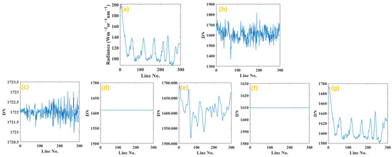
Figure 9.
Longitudinal averages of the laboratory MMS N-WIR (central wavelength of 1368.2 nm) data in linear stretched images. (a) Correctly corrected longitudinal radiance averages of N-WIR and (b) original N-WIR longitudinal DN averages. Longitudinal DN averages based on the (c) HM, (d) MM, (e) BW, (f) TV, and (g) proposed method.
The main novelty of the method proposed in this article is the utilization of the high energy and low radiation interference of the V-NIR spectral band to accurately find uniform regions of N-MIR coefficient measurement by using V-NIR to correct the images (from ground coefficients) under any conditions. Processing using only N-MIR data was first performed with the classical method, with bright and dark regions selected and finally applied on the original N-MIR data. Due to the processing method not being able to completely remove stripe noise, there is a lack of column data when selecting the bright and dark regions. As shown in Figure 10, in the simulated dataset, the MM algorithm is used first to remove noise, and the preliminary corrected error image is then used for uniform region selection. The existence of residual stripe columns will result in insufficient applicability of the uniform region algorithm, causing the column information to be removed and producing striped noise with no data. The above problems will not occur in the method proposed.
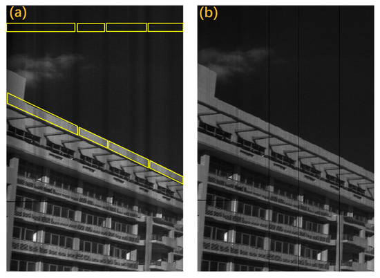
Figure 10.
NUC using N-MIR data only. (a) MM-corrected results (broken yellow boxes mean that a complete row of uniform regions could not be obtained); (b) results of original N-MIR data correction using both MM + uniform region methods show strip noise with no data.
Figure 11 shows the results of the MMS V-NIR simulation data correction. The HM algorithm relied heavily on the selected reference columns, resulting in the destruction of structural information in the image. The MM algorithm partially corrupted the grey scale information in images due to moment matching and averaging of all columns. The BW algorithm removed some of the non-uniform noise resulting from inherent shortcomings in the low-pass filtering process; however, noise remained and the image structure was severely corrupted. The TV algorithm had a component in the direction of the noise bars in all columns such that the non-barred columns lost their grey values, with a step blur after correction for random high-noise bars.
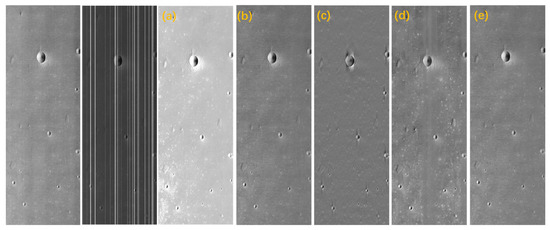
Figure 11.
Correction results for the MMS V-NIR (central wavelength of 950.9 nm) simulation data from linear stretched images. Original V-NIR image (left) and an image with strip noise (second from the left). Correction results based on the different algorithms for the simulated images shown: (a) HM, (b) MM, (c) BW, (d) TV, and (e) the proposed method.
As shown in Figure 12, the longitudinal averages obtained by various methods were curvilinearly compared with the true values after V-NIR simulation data were corrected for non-uniformity. We can see that our method has the closest curve trend to the true value, and, among these methods, we achieved the best results in terms of removing strip noise. The evaluation metric in Table 2 also reflects the proposed method’s excellent non-uniformity correction capability.
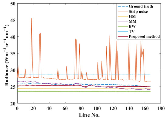
Figure 12.
Longitudinal averages of the MMS V-NIR (central wavelength of 950.9 nm) simulation and denoised data.

Table 2.
Comparison of the objective indicators for the simulated images shown in Figure 8.
3.3. Application Experiment
All the N-WIR channel data from the MMS disturbed by strip noise were processed and the non-uniform noise characteristics of each channel were very similar, with only one representative image of the band (central wavelength of 2433.7 nm) thus selected for illustration. Figure 13 shows the original image of the MMS section (400 pixels × 207 pixels), as well as the image after denoising using the proposed and other methods. Figure 10 shows that the focus is on the two random, apparently anomalous, strip sections in the original image. The original image was reduced by the HM and MM methods for all columns in terms of intra-image information-matching strip noise; however, limited noise remained. The TV method was prone to blurring due to the selection of parameters for regularization. The BW algorithm partially corrupted the grey scale information in the images. The image processed by our method had almost no residual non-uniform noise, and the image was clear with an optimal visual effect.
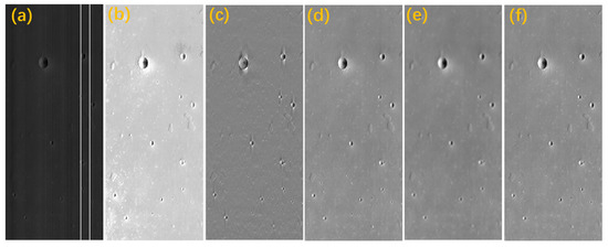
Figure 13.
Correction results for the MMS N-WIR (central wavelength of 2433.7 nm) in-orbit data from linear stretched images. (a) Original image, (b) HM, (c) BW, (d) MM, (e) TV, and (f) the proposed method.
Regarding spectral images, we focus more on whether the information in the spectral dimension is maintained and whether spectral distortions occur, which affect the subsequent analysis and application of the spectral data, while additionally focusing on obtaining optimal visual results by removing non-uniform noise. Therefore, the spectral dimensions of several randomly selected regions (3 × 3 and 5 × 5) on the 2433.7 nm band image were summed and averaged to measure the impact the various methods had on the spectral dimensions. As shown in Figure 11, the spectral dimensional radiance corresponding to some randomly selected pixel values was compared with the original spectral data. The BW method suffered from severe spectral distortion due to normalized calculations, while the HM method had good spectral fidelity, as did the proposed method. We calculated the standard deviation of the spectra obtained by each method from the original image spectral curve, as shown in Figure 14. The results showed that our method had a spectral standard deviation of 0.0539, yielding better spectral fidelity.
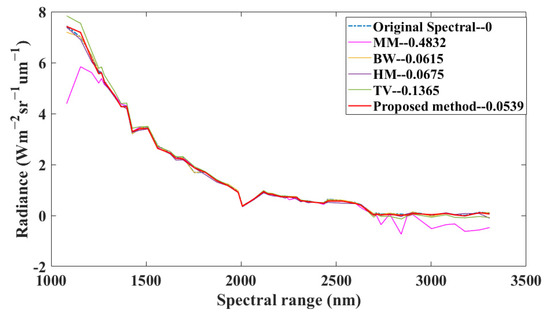
Figure 14.
Spectral irradiance trends in the original image and in one area in the image after processing via different methods.
NR and ICV were used to further quantify the denoising ability of the different methods and their ability to protect the original information in the image. Based on Table 3, the noise reduction ratio and inverse coefficient of variation values for the MMS data when using the proposed method were better than those of the other methods after the quantization and evaluation of all bands in the MMS data. This indicates that our method has an optimal ability to remove non-uniform noise. These results further demonstrate that our method not only has excellent NUC ability, but also has an excellent ability to protect the information in the original image.

Table 3.
Evaluation of MMS data processed by different methods.
These results show that, for the complex non-uniformity of MMS, the BW spectral filtering method seriously destroyed the spectral information in the image. In contrast, with full variational improvements for non-uniformity, the TV method had difficulties obtaining a suitable energy equation, which was more likely to cause incomplete denoising or a loss of details in the spectral image. The HW and MM methods assume that information statistics in the spatial domain can significantly improve the image. However, the a priori assumption that “each element in the image acquires the same energy after push-broom” does not fully hold. It is not sufficiently robust enough to preserve the original information in the image, nor is it sufficiently thorough to suppress unusually prominent noise. After analyzing and verifying the main contributions and shortcomings of the conventional denoising models for the non-uniformity of the MMS, we fully utilized the characteristics of the MMS imaging data to correct the full image via gain and bias in the bright and dark regions selected with the NIR spectrum as a reference, thus obtaining excellent denoising results with improved protection of the original spatial and spectral information while suppressing strip noise. The same conclusion was obtained from image processing results for the additional bands of the MMS. Figure 15 shows a more detailed view of the NUC imaging results using Gaussian stretched imaging maps. The results show that the NUC images using the present method will be beneficial for the quantitative analysis of MMS images in the future. This will facilitate the accurate acquisition and compositional analysis of our hyperspectral images of Mars.
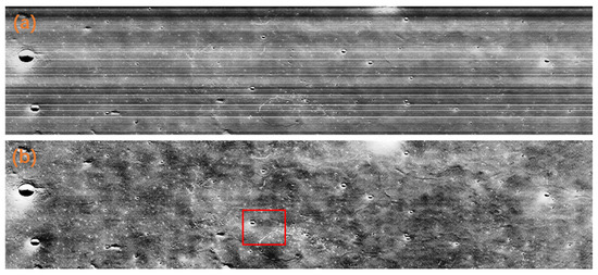
Figure 15.
MMS image (central wavelength of 1931.64 nm) with Gaussian stretching (a) before correction and (b) using the proposed method. The image was rotated, and the frame shows the Zhurong Mars rover landing zone.
4. Conclusions
In this study, the sources and characteristics of non-uniformity were analyzed in terms of sensor hardware and instrumentation, and a NUC method for N-MIR spectral data was proposed. The highlight is the creative use of simultaneous images that are least affected by non-uniformity to obtain bright and dark uniform regions based on spatial segmentation, subsequently solving for correction coefficients. Experiments and applications were performed using hyperspectral data acquired in the MMS laboratory and moored orbit as data sources. The results showed that the proposed method was superior to other commonly used calibration methods and effectively performed NUCs. The proposed method, with bright and dark regions selected with the NIR spectrum as a reference, effectively bridges the non-uniformity generation mechanism of the push-broom hyperspectral detector while obtaining more objective correction coefficients than other methods. As a result, we achieved higher fidelity image details and spectral shapes, thus providing technical support for subsequent MMS hyperspectral data pre-processing. This can provide accurate spectral imaging information for subsequent target identification and the extraction of information related to Martian features. Additionally, the proposed method is not only applicable to MMS hyperspectral data, but also to onboard and airborne hyperspectral imagers with similar configurations to the MMS. In summary, the proposed method has strong universality, low computational load, excellent image detail retention, and high fidelity with spectral shapes.
Author Contributions
Conceptualization, B.W.; formal analysis, B.W.; methodology, B.W. and C.L.; supervision, R.X.; resources, B.L., W.C. and Q.Z.; writing—original draft, B.W. and C.L.; writing—review and editing, Z.H. All authors have read and agreed to the published version of the manuscript.
Funding
This research was funded by China’s first Mars exploration program, the China National Space Administration (CNSA), the National Science Fund for Distinguished Young Scholars (grant no. 62125505), the Shanghai Outstanding Academic Leaders Plan, and the Program of the Shanghai Academic/Technology Research Leader (no. 19XD1424100).
Data Availability Statement
The data involved in this research can be requested from the Lunar and Planetary Management System at https://moon.bao.ac.cn/web/zhmanager/mars1. accessed on 15 August 2021.
Conflicts of Interest
The authors declare no conflict of interest.
References
- Mouzali, S.; Lefebvre, S.; Rommeluere, S.; Ferrec, Y.; Primot, J. Modeling of HgCdTe focal plane array spectral inhomogeneities. In Proceedings of the SPIE9520, Integrated Photonics: Materials, Devices, and Applications III, Barcelona, Spain, 4–6 May 2015; Volume 95200S, pp. 1–7. [Google Scholar]
- Arslan, Y.; Oguz, F.; Besikci, C. Extended wavelength SWIR InGaAs focal plane array: Characteristics and limitations. Infrared Phys. Technol. 2015, 70, 134–137. [Google Scholar] [CrossRef]
- Naratanan, B.; Hardie, R.C.; Muse, R.A. Scene-based nonuniformity correction technique that exploits knowledge of the focal-plane array readout architecture. Appl. Opt. 2005, 44, 3482–3491. [Google Scholar] [CrossRef] [PubMed]
- Ratliff, B.M.; Hayat, M.M.; Tyo, J.S. Radiometrically accurate scene-based nonuniformity correction for array sensors. J. Opt. Soc. Am. A 2003, 20, 1890–1899. [Google Scholar] [CrossRef] [PubMed]
- Simpson, J.J.; Stitt, J.R.; Leath, D.M. Improved finite impulse response filters for enhanced destriping of geostationary satellite data. Remote Sens. Environ. 1998, 66, 235–249. [Google Scholar] [CrossRef]
- Chen, J.; Shao, Y.; Guo, H.; Wang, W.; Zhu, B. Destriping CMODIS data by power filtering. IEEE Trans. Geosci. Remote Sens. 2003, 41, 2119–2124. [Google Scholar] [CrossRef]
- Pande-Chhetri, R.; Abd-Elrahman, A. De-striping hyperspectral imagery using wavelet transform and adaptive frequency domain filtering. ISPRS J. Photogramm. Remote Sens. 2011, 66, 620–636. [Google Scholar] [CrossRef]
- Münch, B.; Trtik, P.; Marone, F.; Stampanoni, M. Stripe and ring artifact removal with combined wavelet:Fourier filtering. Opt. Express 2009, 17, 85678591. [Google Scholar] [CrossRef]
- Shen, H.F.; Zhang, L.P. A MAP-based algorithm for destriping and inpainting of remotely sensed images. IEEE Trans. Geosci. Remote Sens. 2009, 47, 1492–1502. [Google Scholar] [CrossRef]
- Bouali, M.; Ladjal, S. Toward optimal destriping of MODIS data using a unidirectional variational model. IEEE Trans. Geosci. Remote Sens. 2011, 49, 2924–2935. [Google Scholar] [CrossRef]
- Wang, M.; Huang, T.Z.; Zhao, X.L.; Deng, L.J.; Liu, G. A unidirectional total variation and second-order total variation model for destriping of remote sensing images. Math. Probl. Eng. 2017, 2017, 4397189. [Google Scholar] [CrossRef]
- Wegener, M. Destriping multiple sensor imagery by improved histogram matching. Int. J. Remote Sens. 1990, 11, 859–875. [Google Scholar] [CrossRef]
- Rakwatin, P.; Takeuchi, W.; Yasuoka, Y. Stripe noise reduction in MoDIS data by combining histogram matching with facet filter. IEEE Trans. Geosci. Remote Sens. 2007, 45, 18441856. [Google Scholar] [CrossRef]
- Cao, B.; Du, Y.; Xu, D.; Li, H.; Liu, Q. An improved histogram matching algorithm for the removal of striping noise in optical remote sensing imagery. Optik 2015, 126, 4723–4730. [Google Scholar] [CrossRef]
- Leathers, R.A.; Downes, T.V.; Priest, R.G. Scene-based nonuniformity corrections for optical and SWIR push-broom sensors. Opt. Express 2005, 13, 5136–5150. [Google Scholar] [CrossRef]
- Jia, J.; Wang, Y.; Cheng, X.; Yuan, L.; Zhao, D.; Ye, Q.; Zhang, X.; Shu, R.; Wang, J. Destriping algorithms based on statistics and spatial filtering for visible-to-thermal infrared push-broom hyperspectral imagery. IEEE Trans. Geosci. Remote Sens. 2019, 57, 4077–4091. [Google Scholar] [CrossRef]
- Hu, B.L.; Hao, S.J.; Sun, D.X.; Liu, Y.N. A novel scene-based non-uniformity correction method for SWIR push-broom hyperspectral sensors. ISPRS J. Photogramm. Remote Sens. 2017, 131, 160–169. [Google Scholar] [CrossRef]
- Zhou, J.; Kwan, C.; Ayhan, B. Improved target detection for hyperspectral images using hybrid in-scene calibration. J. Appl. Remote Sens. 2017, 11, 035010. [Google Scholar] [CrossRef]
- Bell, J.F., III; Pollack, J.B.; Geballe, T.R.; Cruikshank, D.P.; Freedman, R. Spectroscopy of Mars from 2.04 to 2.44 mm during the 1993 opposition: Absolute calibration and atmospheric vs. mineralogic origin of narrow absorption features. Icarus 1994, 111, 106–123. [Google Scholar] [CrossRef]
- Clark, R.N. Reflectance spectra. In Rock Physics & Phase Relations: A Handbook of Physical Constants; Ahrens, T.J., Ed.; AGU Ref. Shelf 3; AGU: Washington, DC, USA, 1995; pp. 178–188. [Google Scholar]
- Ehlmann, B.L.; Edwards, C.S. Mineralogy of the Martian Surface. Annu. Rev. Earth Planet. Sci. 2014, 42, 291–315. [Google Scholar] [CrossRef]
- He, Z.; Xu, R.; Li, C.; Yuan, L.; Liu, C.; Lv, G.; Jin, J.; Xie, J.; Kong, C.; Li, F.; et al. Mars Mineralogical Spectrometer (MMS) on the Tianwen-1 Mission. Space Sci. Rev. 2021, 217, 27. [Google Scholar] [CrossRef]
- He, Z.P.; Wu, B.; Xu, R.; Liu, C.; Li, C.; Yuan, L.; Lv, G.; Jin, J. Detection mechanism and instrument characteristics of the Mars Mineralogical Spectrometer for the Tianwen-1 orbiter. Sci. Sin. Phys. Mech. Astron. 2022, 52, 239503. (In Chinese) [Google Scholar] [CrossRef]
- Gui, Y.; Li, J.; Wang, M.; He, Z. Research and application of spectroscopic techniques in lunar and Mars exploration missions. J. Infrared Millim. Waves 2021, 42, 1730001-1730001-11. [Google Scholar]
- Liu, B.; Ren, X.; Liu, D.; Liu, J.; Zhang, Q.; Huang, H.; Xu, R.; Wang, R.; Liu, C.; He, Z.; et al. Ground Validation Experiment and Spectral Detection Capability Evaluation of Mars Mineralogical Spectrometer (MMS) Aboard HX-1 Orbiter. Space Sci. Rev. 2022, 218, 1. [Google Scholar] [CrossRef]
- Zhang, X.; Feng, R.; Li, X.; Shen, H.; Yuan, Z. Block adjustment-based radiometric normalization by considering global and local differences. IEEE Geosci. Remote Sens. Lett. 2020, 19, 1–5. [Google Scholar] [CrossRef]
Disclaimer/Publisher’s Note: The statements, opinions and data contained in all publications are solely those of the individual author(s) and contributor(s) and not of MDPI and/or the editor(s). MDPI and/or the editor(s) disclaim responsibility for any injury to people or property resulting from any ideas, methods, instructions or products referred to in the content. |
© 2023 by the authors. Licensee MDPI, Basel, Switzerland. This article is an open access article distributed under the terms and conditions of the Creative Commons Attribution (CC BY) license (https://creativecommons.org/licenses/by/4.0/).