Communication

Analysis and Simulation of a Sequential Rotationally Excited Circular Polarized Multi-Dipole Array for a Bi-Static Antenna GPR for Deep Exploration

1
Faculty of Information Technology, Beijing University of Technology, Beijing 100124, China
2
College of Artificial Intelligence, Tianjin University of Science and Technology, Tianjin 300457, China
3
School of Transportation Science and Engineering, Civil Aviation University of China, Tianjin 300300, China
*
Author to whom correspondence should be addressed.
Remote Sens. 2023, 15(4), 1134; https://doi.org/10.3390/rs15041134
Submission received: 13 December 2022 / Revised: 1 February 2023 / Accepted: 16 February 2023 / Published: 19 February 2023

Abstract

:
As an effective active remote sensing technology for the exploration of shallow underground targets, ground-penetrating radar (GPR) is a detection method that can be used to obtain information about the characteristics of underground targets by transmitting an electromagnetic wave from an antenna and analyzing the propagation of the electromagnetic wave underground. Due to the frequency (1 MHz–3 GHz) of GPRs, the depth of geological exploration is shallow (0.1–30 m). In order to penetrate the deeper Earth, it is necessary to increase the size of the antenna in accordance with the wavelength ratio and, thus, reduce the radiation frequency. For most bi-static antenna GPRs, a dipole antenna is used as the transmitting antenna and another antenna device is used as a receiving antenna, with both being horizontally linearly polarized (LP) antennas. In some cases, such a design can cause problems, such as the multi-path effect and polarization mismatching. When a GPR is used for deep exploration, increased numbers of errors and greater signal attenuation during data reception and processing often occur. In contrast, at the radiation source, with the use of large-aperture multiple-dipole antennas and multi-channel sequential rotational excitation, the electromagnetic wave can radiate in the form of circular polarization at a low frequency. In the receiving antenna, the issues caused by the multi-path effect and polarization mismatching can be addressed, even if LP antennas are used. A novel sequential rotationally excited (SRE) circularly polarized (CP) multiple-dipole array for a bi-static antenna GPR for deep exploration is proposed in this paper. A large-aperture CP multiple-dipole array is used instead of a small-size LP dipole antenna. The analysis and simulation results demonstrated that, comparing circular polarization and linear polarization with the premise of the same transmitting power, the SRE CP multiple-dipole antenna array radiation source achieved a significant enhancement (about 7 dB) in the signal-to-noise ratio (SNR) as the radiant energy was collected at the receiving antenna. More importantly, by reducing the exploration frequency to 10 KHz, the exploration depth could also be greatly increased by about tenfold.

1. Introduction

Ground-penetrating radar (GPR) technology is an active remote sensing method that uses electromagnetic waves with frequencies ranging from 1 MHz to 3 GHz to detect the internal structure of media. Following long-term development, it has been applied in many fields, such as archaeology, traffic construction and maintenance, water conservancy project detection, urban construction, disaster geological monitoring, environmental research, agricultural geological research, and geological structure detection [1,2,3,4,5]. GPRs use a high-frequency electromagnetic wave as the remote sensing carrier, which results in high resolution [6,7,8] but also causes serious attenuation of the effective signals. For this reason, the maximum detection depth is only about 30 m, which has severely limited the development of the GPR method.
As important aspects of bi-static antenna GPR systems, transmitting and receiving antennas play key roles in sounding [9,10,11]. In 2015, several scholars [12] combined multiple-input multiple-output (MIMO) antenna technology with multi-polarization technology to overcome the interference caused by changes in the antenna radiation direction and target scattering cross-sectional area in the measurement process, and the detection accuracy for underground targets was significantly improved. It was shown that the high-depth GPR system proposed by Xu Xianlei [13] in 2018 could work at 12.5 MHz–50 MHz, and the corresponding antenna lengths were 8.25 m–2.25 m. The corresponding main-frequency antenna was used for different detection depth requirements, and the maximum detection depth reached 80 m in coal mine detection, with weak attenuation and positioning accuracy that reached 3 m. In 2019, the Chinese Academy of Sciences successfully loaded the Chang’e-4 lunar lander with dual-channel antennas (60 MHz and 500 MHz) [14], making it possible to obtain a large amount of precious lunar geological data. Different channels correspond to different detection depths and resolutions. However, in high-depth GPR remote sensing, conventional methods do not easily meet the requirements.
In most bi-static antenna GPRs, a dipole antenna is used as the transmitting antenna, and another antenna device is used as a receiving antenna, with both being horizontally linearly polarized (LP) antennas. In some cases, such a design can cause problems, such as the multi-path effect and polarization mismatching [15]. When a GPR is used for deep exploration, increased numbers of errors and greater signal attenuation during data reception and processing often occur [16]. Active remote sensing refers to a remote sensing system in which a certain form of electromagnetic wave is emitted to the target from an artificial radiation source on a remote sensing platform. Then, the reflected wave is received and recorded by the receiving antenna. The main advantage of such systems is that they can operate day and night without relying on solar radiation [17,18,19,20], and the wavelength and emission mode of the electromagnetic wave can be actively chosen according to the purpose of the detection. Generally speaking, the electromagnetic waves used in active remote sensing are microwaves.
In traditional bi-static antenna GPRs, the electromagnetic wave radiated by the grounded dipole antenna is generally divided into the underground direct wave, underground reflected wave, sky wave, and side wave [21,22,23]. As shown in Figure 1, the sky wave is an electromagnetic wave that shoots into the sky at a large angle. These electromagnetic waves are generally consumed or reflected by the ionosphere and rarely captured by the remote receiver. A direct wave is an electromagnetic wave spread along a straight line from the transmitter to the receiver. This form of electromagnetic wave only passes through soil, similar to the transmission principle for electromagnetic waves in free space.
When the angle of the incident wave is smaller than the critical angle, the electromagnetic wave diffuses into the ground, is reflected back into the soil medium through the interface of the soil and air, and then diffuses to the receiver. This form of electromagnetic wave is called a reflected wave, and it is also transmitted only through soil.
When an electromagnetic wave is transmitted through the interface of two kinds of media (e.g., soil and air), if the wave velocity differs on either side of the interface—that is, C 1 is less than C 2 —and the incident wave angle of the electromagnetic wave at the interface is greater than the critical angle, the incident electromagnetic wave diffuses to and passes through the interface of the soil and air, is transmitted for a distance in the air, and then enters the soil at a position near the receiver. The defining characteristic of the side wave is that it is the first to reach the receiver, before the direct wave and the reflected wave, because in this mode, part of the electromagnetic wave propagation also takes place in the air, and the transmission speed of the electromagnetic wave in the air is greater than that in the soil. When the buried depth of the transmitting antenna is relatively small, the received wave energy is mostly side-wave energy.
As the electromagnetic wave radiated by a grounded dipole antenna is horizontally linearly polarized, the electric field propagates parallel to the ground, which results in a high induced current in the ground, resulting in significant attenuation of the electromagnetic wave. Therefore, the attenuation factor A h for the horizontal-polarization wave on the ground and underground is far greater than that for the vertical-polarization wave ( A v ) [24,25]. When the receiving antenna is in the far field, the underground direct wave and reflected wave are seriously attenuated, meaning that the received energy mainly depends on the propagation of the side wave. Then, in the direction of propagation of the electromagnetic wave, the corresponding electric field and magnetic field components and phase delay are recorded by the receiving antenna. Furthermore, the Cagniard resistivity is calculated using Equation (1). As it is LP, when the side wave reaches the receiving antenna, the electric field signal in the y-axis is significantly higher than that in the x-axis, which significantly affects the calculation of the vector Cagniard resistivity. Results show that the greater the signal-to-noise ratio (SNR) is, the more accurate the Cagniard resistivity calculation [4] is.
ρ = 1 ω μ | E y H x | 2
where μ is the permeability and the angular frequency ω = 2 π f .
When the electromagnetic wave propagates in the form of a side wave, it may reach the receiving antenna directly or it may encounter obstacles on the ground first and then reach the receiving antenna after being reflected [26]. In addition, it may encounter obstacles underground, such as faults, cavities, and mineral deposits. The transmitted wave may also return to the receiving antenna via two paths: either directly or after being reflected by obstacles or other elements. Therefore, among the echo signals received by the receiving antenna, in addition to the direct signal, there is also the signal reflected back from obstacles or other elements. As the direct signal and the reflected signal can be regarded as sent from the same transmitting source and the two signals are strongly correlated, it is difficult for conventional antennas to distinguish the real echo signal of the target [27,28,29,30]; that is, the wave front is discontinuous due to the frequency dependence of the different media’s parameters, meaning that the electromagnetic wave reaches the receiving antenna along multiple paths. The delayed arrival of the scattering part of the signal leads to problems such as attenuation, the steep wall effect, and the indirect reception of gloves, causing changes in the amplitude and phase of the echo signal that lead to the multi-path effect [31].
Moreover, in terms of linear polarization, the maximum induced signal can only be obtained when the polarization direction of the receiving antenna is completely consistent with the polarization direction of the transmitting antenna; otherwise, loss of polarization isolation above 10 dB occurs. During long-distance transmission of horizontally LP electromagnetic waves, polarization is easily deflected when obstacles are encountered. In this way, the electromagnetic wave can easily cause polarization mismatching and partial energy loss after reaching the receiving antenna. The LP mode requires higher directivity in the transmitting antenna, while the radiative electric field vector of a circularly polarized (CP) wave rotates in the propagation direction (left or right), and the instantaneous trajectory is circular. If the polarization surface rotates with time and has a right-spiral relationship with the propagation direction of the electromagnetic wave, it is called right-circular polarization; in contrast, if the relationship is a left-spiral relationship, it is called left-circular polarization. When a CP wave encounters an obstacle, it will refract and reflect. The rotation direction after refraction remains unchanged, while it is reversed during reflection. Opposite-direction rotation entails better polarization isolation, which can effectively reduce the impact of multi-path effect interference. Moreover, a rotating electric field vector has better penetration ability, significantly reducing the propagation loss. We know that the electromagnetic waves radiated by any antenna are elliptical polarized waves, and the extreme cases are LP and CP waves. A traditional GPR is loaded with an LP antenna and radiates LP waves. A linear polarization wave is easily affected by climate, the environment, the carrier movement direction, and other factors, resulting in polarization deflection loss and even failure, making it difficult to meet the requirements of the new era of ground exploration. The loss in polarization deflection for CP waves radiated by CP antenna is small, and polarization reversal occurs when they encounter a reflector. In the process of ground exploration, the causes of polarization deflection loss are not restricted to the placement orientation of the antenna, which is oriented to ensure that the ground exploration equipment can operate normally. The loss in polarization distortion caused by the Faraday rotation effect may also be eliminated when minerals such as magnetized ferrite are encountered in the Earth. Therefore, GPRs are widely used in GPSs, Beidou, RFID, and other communication systems [32,33]. In addition, theoretically, under the same conditions as LP waves, CP waves are simultaneously divided into horizontal and vertical components. When LP antennas are used as receiving antennas, the field intensity of CP waves is 3 dB lower than that of LP waves; that is, CP waves can be received by any LP antenna. Although some energy is lost, the receiving antenna does not need to be aligned with the direction of the signal. This can also make up for the multi-path effect and polarization mismatch.
As a conventional radiation source for GPR, the dipole antenna is composed of two conductors that are fed in the center, with a total length of about half a wavelength. After forming an array with multiple-dipole antennas, by controlling the amplitude ratio, the phase of the current in the dipole antenna, and the spatial position, such multiple-dipole antennas can be applied as base station antennas, CP antennas, MIMO antennas, Yagi antennas, and in other application scenarios [34]. In this paper, a novel GPR with an SRE CP multiple-dipole array of bi-static antennas for deep exploration is proposed that uses a large-aperture CP MD array instead of a small-size LP dipole antenna. The analysis and simulation results demonstrated that, comparing circular polarization and linear polarization with the premise of the same transmitting power, the SRE CP multiple-dipole antenna array radiation source achieved a significant enhancement (about 7 dB) in the signal-to-noise ratio (SNR) as the radiant energy was collected at the receiving antenna. More importantly, by reducing the exploration frequency to 10 KHz, the exploration depth could also be greatly increased by about tenfold.

2. Principle of SRE Circular Polarization

2.1. Interference and Superposition Principle for Electromagnetic Waves

Calculation and simulation show that, when multiple-dipole antennas are placed perpendicularly to each other to build an MD array, the radiation patterns of the E- and H-planes of the MD array are symmetrical. If the multiple-dipole antennas are fed with the same amplitude and 90° phase difference, it is a CP antenna system [35].
The electromagnetic waves radiated by each dipole antenna constituting the MD array interfere with and are superimposed on each other in space [36]. Utilizing this phenomenon, by changing the amplitude and phase excitation of each element of the array, the strength and weakness of the electromagnetic field in a certain area within the radiation range can be flexibly controlled [37]. Therefore, compared with single-dipole antenna elements, array antennas provide a higher degree of freedom in design.
The radiation of an antenna through space is generated by the source current in the antenna. If there are multiple currents meeting the coherence relationship in space, the electromagnetic fields radiated by the multiple currents will overlap in space, creating interference [38]. The superposition of electromagnetic waves in the same phase will increase the field strength, while the superposition of electromagnetic waves in the opposite phase will reduce the field strength, which also leads to the uneven distribution of electromagnetic field strength in space. The radiated electromagnetic field generated by the current distribution J in a uniform medium can be expressed as
E = j ω A j 1 ω μ ε ( · A )
H = 1 μ × A
where A represents the vector magnetic potential, μ represents the relative permeability of the medium, and ε represents the relative permittivity of the medium.
According to the Helmholtz equation:
2 A + k 2 A = μ J
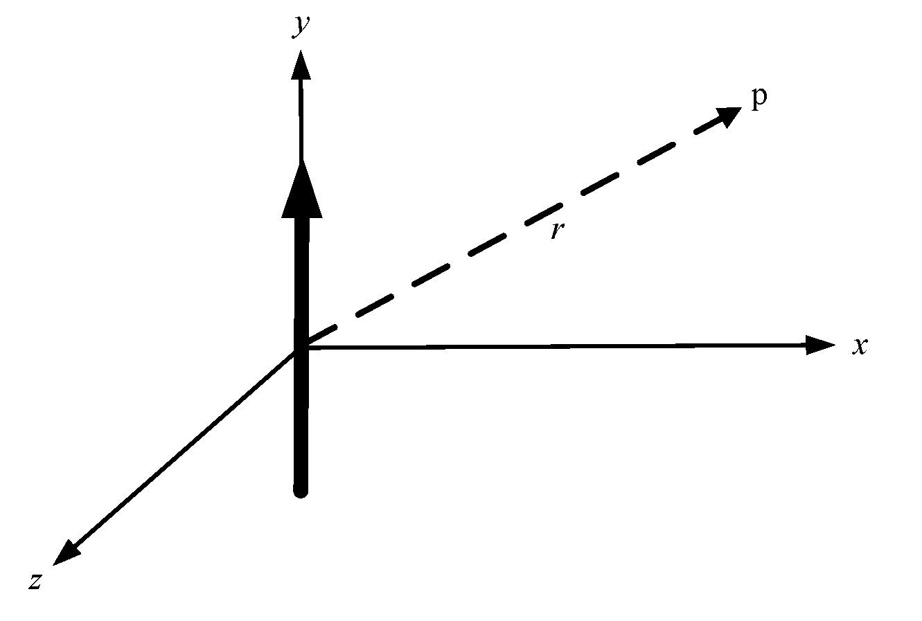
where J represents the current density for linear radiation sources, which is also applicable to surface radiation sources. As shown in Figure 2, the linear current density J is along the y-axis direction.
If the line length is L and r represents the distance between the current source and the space observation point, then the superposed magnetic vector A of the field at the space observation point is
A = y μ 4 π J y ( y ) e j k r r d y
The integral operation is actually the result of the summation of an infinite number of parts. If the linear radiation source is equivalent to N small-current segments, then the superposition in space of the magnetic vectors of the radiation points generated by each segment represents the vector magnetic potential of the total radiation field.
A T = n = 1 N A n = y μ 4 π n = 1 N I n e j k r n r n
Therefore, the magnetic vector potential of the total radiation field synthesized somewhere in the space of the linear radiation source with N can be represented by the superposition vector of the N magnetic vector potential. Similarly, the surface current source can also be obtained via the superposition of the N -equivalent small-current surface radiation fields. Therefore, the discrete current source can be used to replace the continuous current radiator to achieve equivalent electromagnetic wave radiation.

2.2. Principle of Pattern Multiplication

According to the superposition theory of space for electromagnetic waves, an equivalent linear radiation source can be obtained when tiny antennas are arranged in a linear form. When tiny antennas are arranged in a planar form, the equivalent planar radiation source is obtained. Therefore, for the same antenna element, a different array arrangement can result in different array performance, indicating that array arrangement has a certain impact on the performance of array antennas.
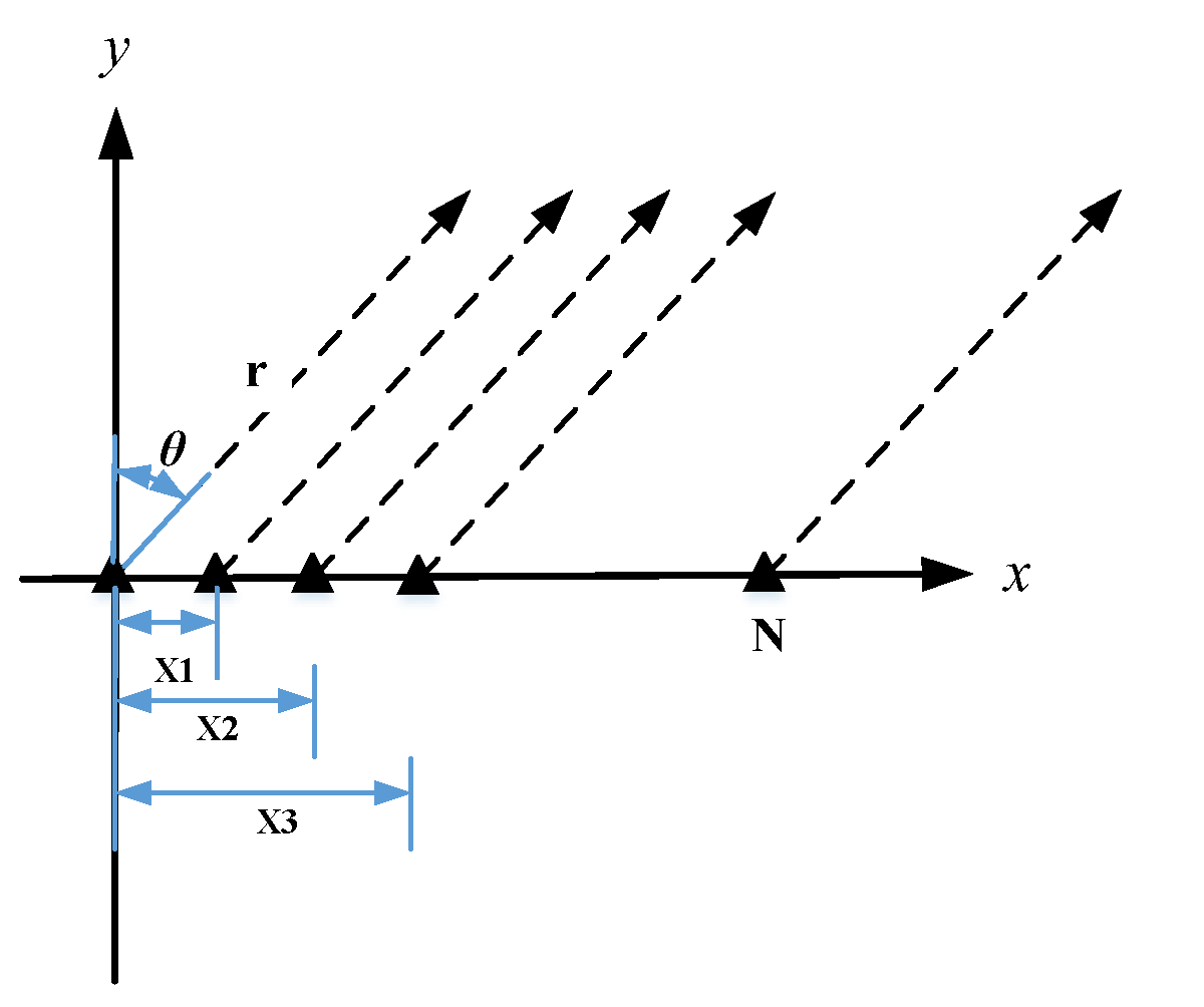
Considering Figure 3 and taking the linear array as an example, suppose that the antenna units are arranged with a certain spacing along the x-axis and assume that the position of each antenna unit is indicated by the coordinate x n in relation to the origin. Additionally, the pattern function of each antenna is F e ( θ , φ ) , which is called the element factor.
Assuming that the excitation of each antenna unit is I , the field strength generated by it will be positively correlated with the excitation of each antenna unit. Then, in spherical coordinates, at point P ( r , θ , φ ) , electric field radiation is generated. The electric field radiation generated by the Nth antenna unit at point P ( r , θ , φ ) is:
E N = A I N e j k r N 4 π r N F e ( θ , φ )
where r N r x N cos θ . Taking r N from Equation (7), according to the principle of spatial electromagnetic wave superposition, the size of the composite electromagnetic field of each unit in the linear array at point P ( r , θ , φ ) in space is
E T = 1 N E N = A e j k r 4 π r F e ( θ , φ ) 1 N I N e j k x N cos θ
where e j k x N cos θ represents the relative phase of the electromagnetic wave radiated by each unit to the point P ( r , θ , φ ) due to the difference in position. Then, the array factor is 1 N I N e j k x N cos θ .
From this, it can be seen that the pattern characteristic of an array antenna is equal to the characteristic factor of an element antenna multiplied by the characteristic factor corresponding to the array characteristic.

2.3. Principle of Sequential Rotationally Excited Circular Polarization

In practical circular polarization array designs, the sequential rotation technique is usually used to achieve a symmetrical pattern and improve the axial ratio bandwidth of the circular polarization, allowing it to be used in various broadband applications [35]. Multiple linear polarization antennas can be used to produce a circularly polarized antenna with good performance and relatively wide axial ratio bandwidth. In this method, the antenna elements are successively rotated by 90° to arrange their structure. In accordance with the equal feeding amplitudes of each element, a feed phase with a sequence difference of 90° is fed to them, meaning that good circular polarization characteristics can be obtained.
The sequential rotation array technique applied in this study was the rotation of the array positions of four antenna elements in any polarization mode by 90° in turn; with this technique, the feeding amplitudes of the four elements must be equal, and the phase difference is 90°. Using this unique technique, an array antenna composed of linear polarization elements can be used to generate CP electromagnetic waves while greatly reducing its complexity, weight, and feed network loss. Compared with the traditional array arrangement, the mutual coupling between elements can be greatly reduced by using the sequential rotation arrangement because adjacent elements are placed vertically. In addition, in a wide frequency band, this unique arrangement can enable the main beam to maintain good circular polarization characteristics within a certain angle range away from the maximum radiation direction.
When using this technique, the nth element in an equidistant annular array must have a physical rotation angle around the geometric center of the element φ p n , and for the feed phase shift φ e n , the physical rotation angle and feeding phase must meet the following conditions:
φ p n = ( n 1 ) p π N , 1 n N
φ e n = ( n 1 ) p π N
where p is the sequential rotation coefficient and N is the total number of radiation units. For the case of N = 2 and p = 1 , it can be deduced from the formula above that φ e 1 = φ p 1 = 0 and φ e 2 = φ p 2 = 90 . When N = 4 and p = 2 , the rotation angles and feed phases of each unit are 0°, 90°, 180°, and 270°, respectively. This configuration was the structure adopted for the sequential rotation array designed in this part of the study.

3. Simulation of Dipole Antenna

We assumed that a dipole antenna with an arm length of 0.75 km was placed along the y-axis in an air domain; this structure is shown in Figure 4. The air domain was assumed to be a uniform sphere with a radius of 7.5 km. AC excitation of 1000 V and 10 KHz was used with the dipole antenna lumped port.
Figure 5 shows the distribution and direction of the electric field on the dipole antenna plane. It can be seen that the electromagnetic wave propagated outward in the form of linear polarization, and the polarization direction was parallel to the placement direction of the dipole antenna.

4. Simulation of SRE Circular Polarization Based on the MD Array

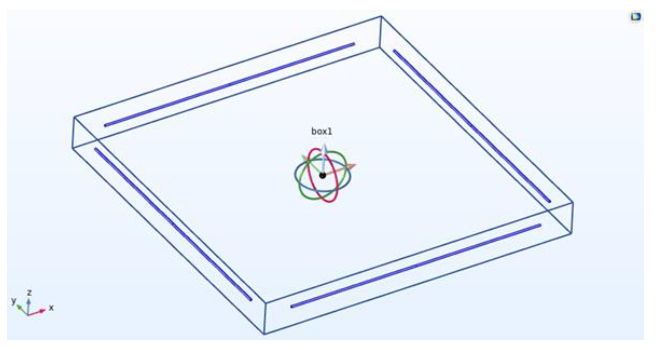
Figure 6 shows the structure of a CP MD antenna array model in COMSOL. Four dipole antennas with arm lengths of 0.75 km were placed on four sides of a square area with a side length of 1.8 km. The feed phases and rotation angles of the four dipole antennas of the array were 0°, 90°, 180°, and 270°, respectively, and each dipole antenna needed to be excited with an equal amplitude (1000 V) at 10 KHz.

4.1. Electric Field Simulation for SRE Circular Polarization

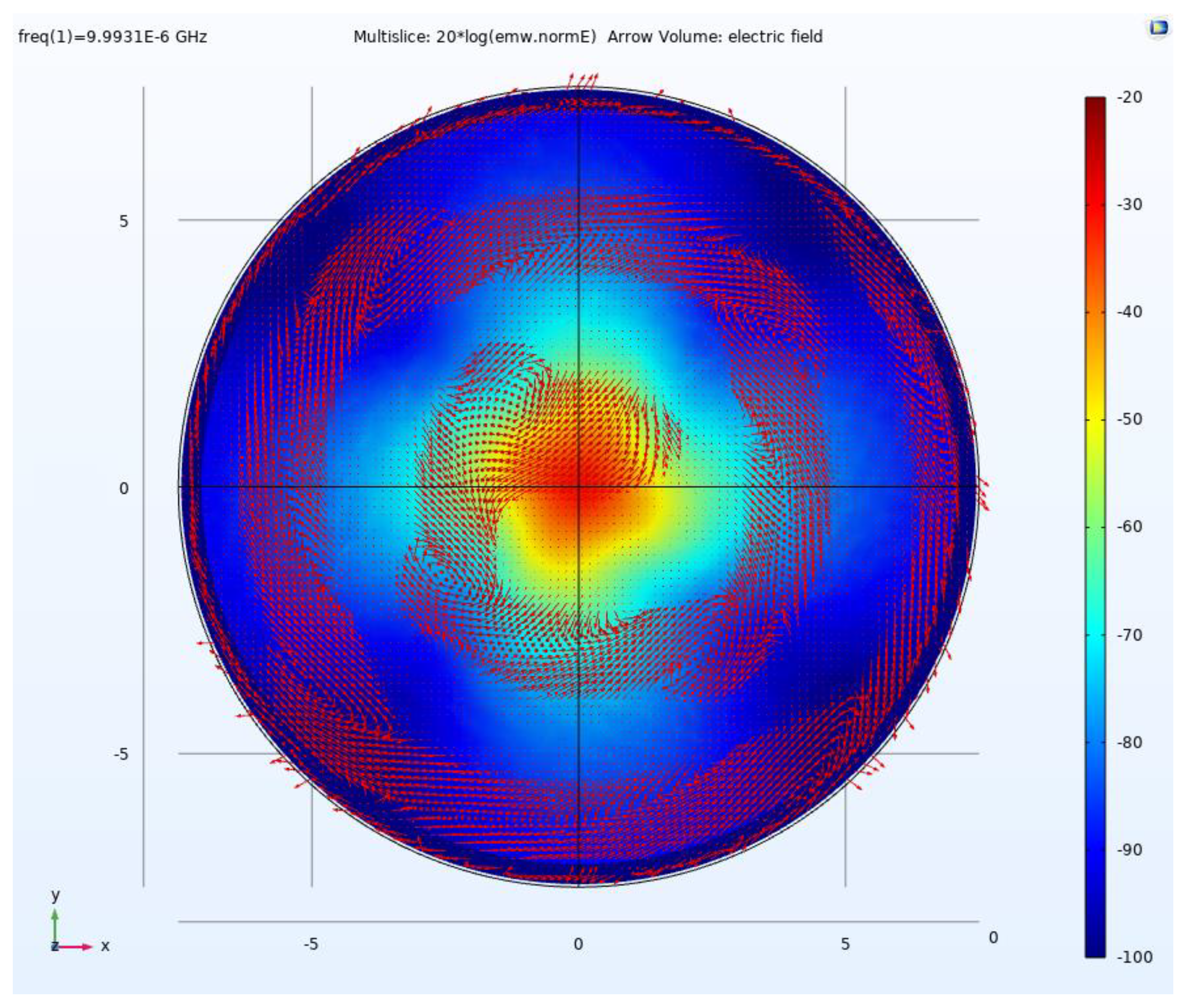
According to the settings shown in Figure 6, an MD array was placed in the airspace, which was a sphere with a radius of 7.5 km. Figure 7 shows the electric field distribution on the MD plane.
It can be seen from Figure 7 that the electric field distribution was rearranged, and the electric field was rotated after the sequential rotation of the four dipole antennas, completing the transformation from LP to CP.
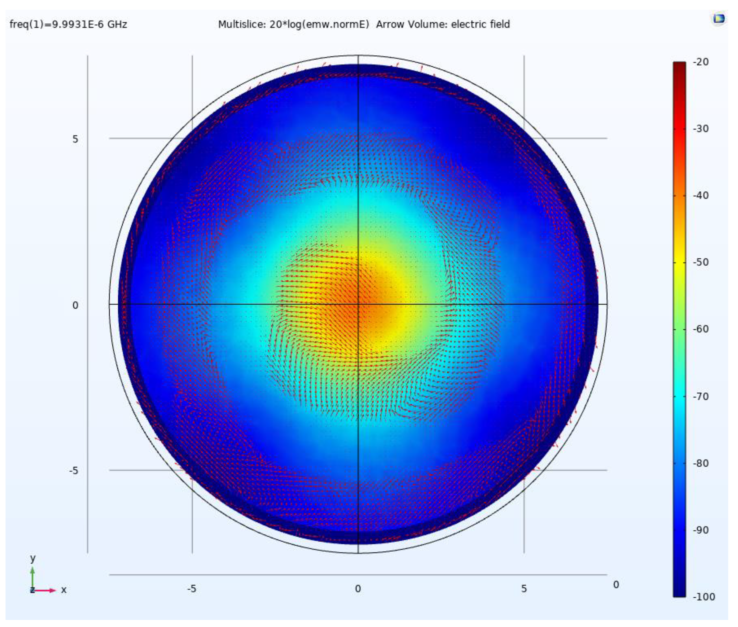
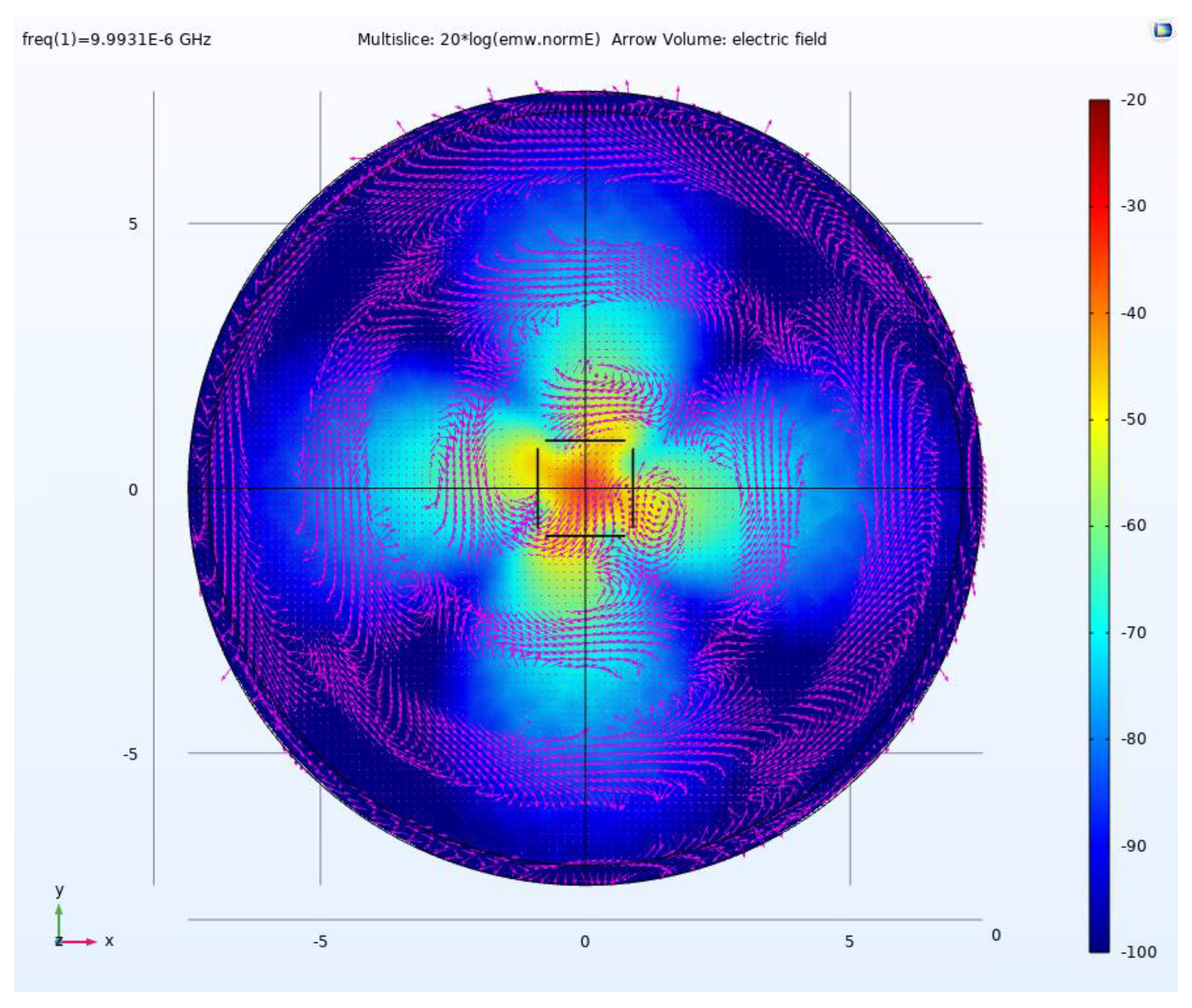
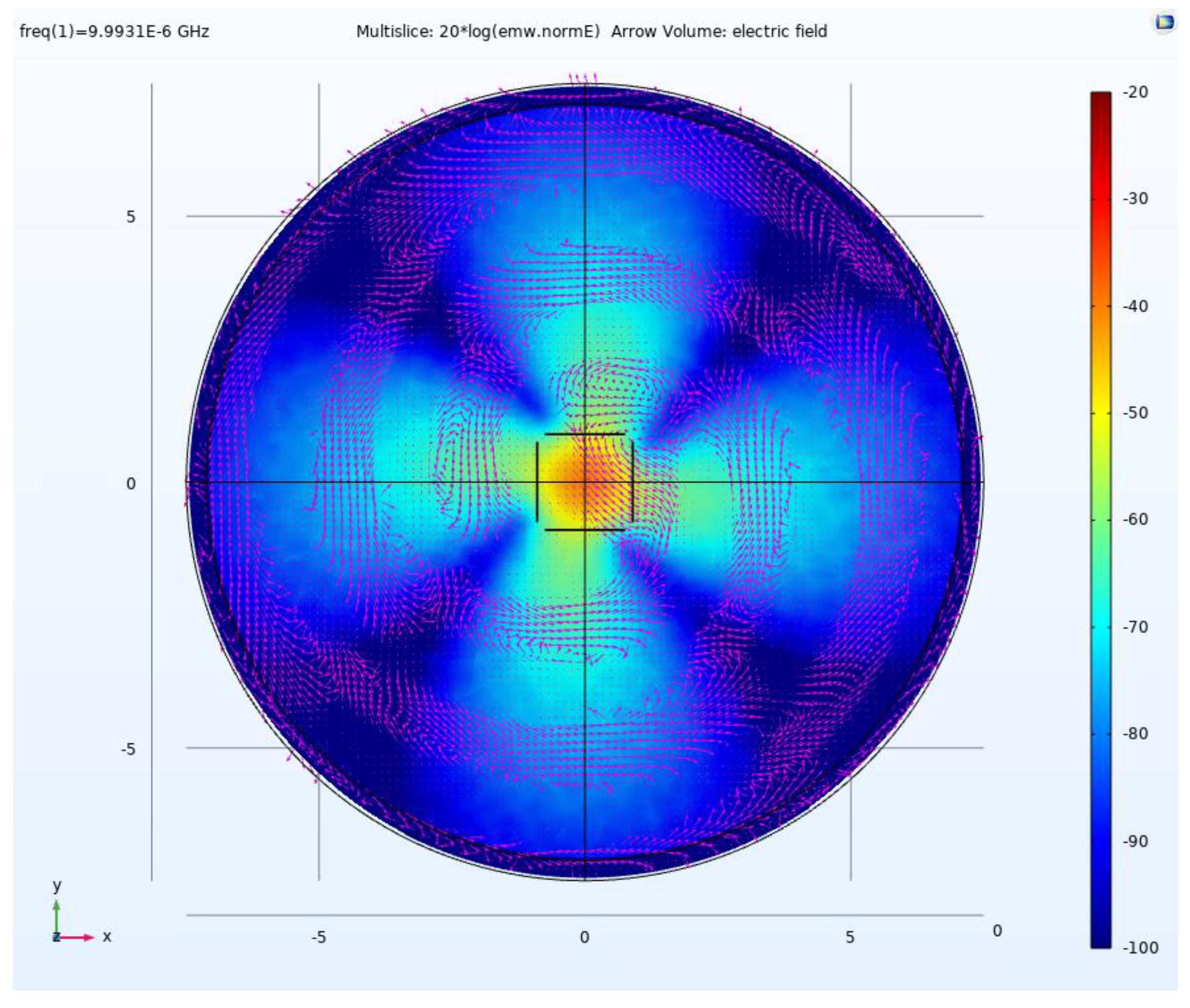
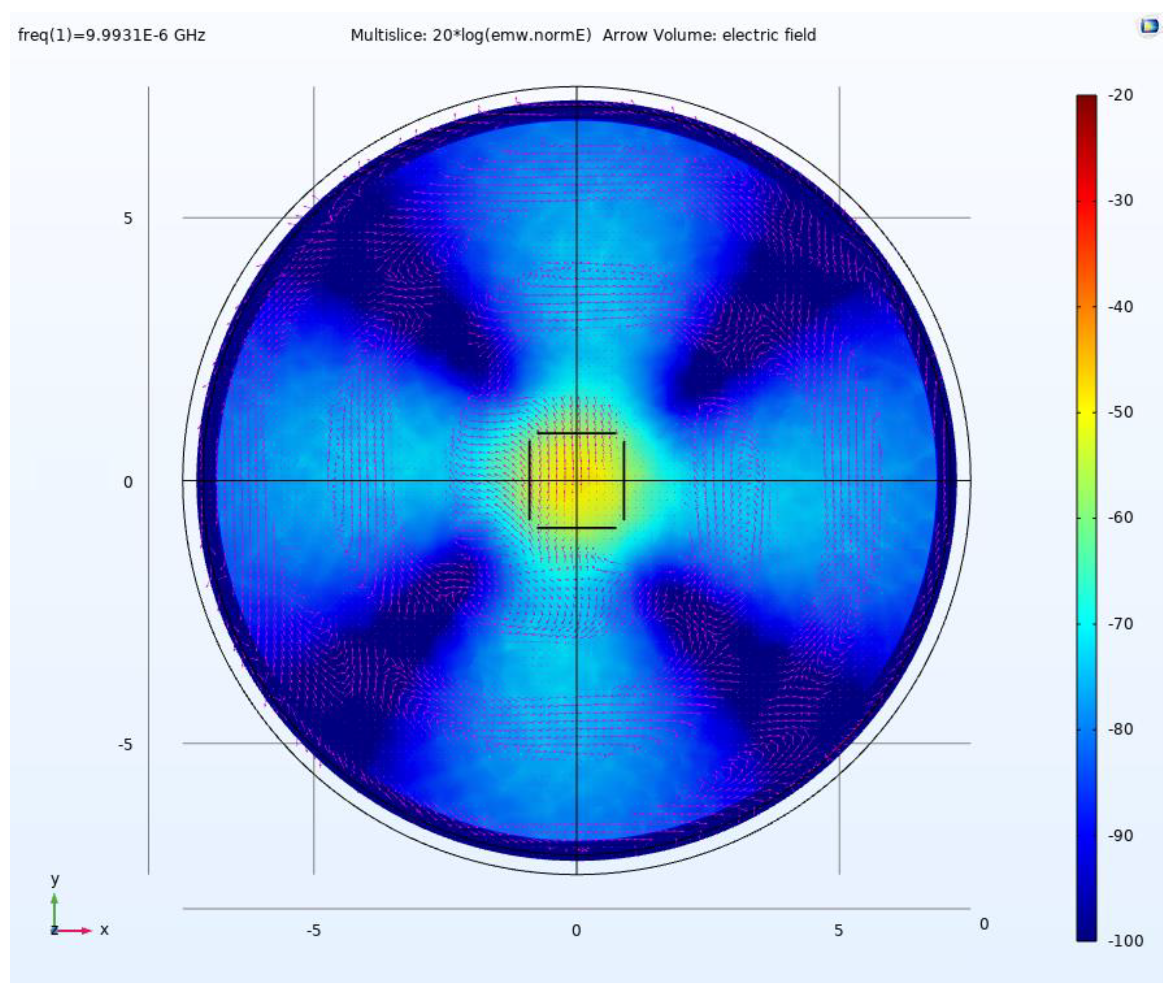
Figure 8, Figure 9 and Figure 10 show the electric field distributions and directions at heights of 0 km, 10 km, and 20 km away from the MD plane, respectively.
It can be clearly seen that the electric field rotated in the direction of electromagnetic wave propagation, and the track in the direction of the electromagnetic wave propagation was circular; that is, the electromagnetic wave propagated in a circularly polarized manner.

4.2. Far-Field Simulation of SRE Circular Polarization

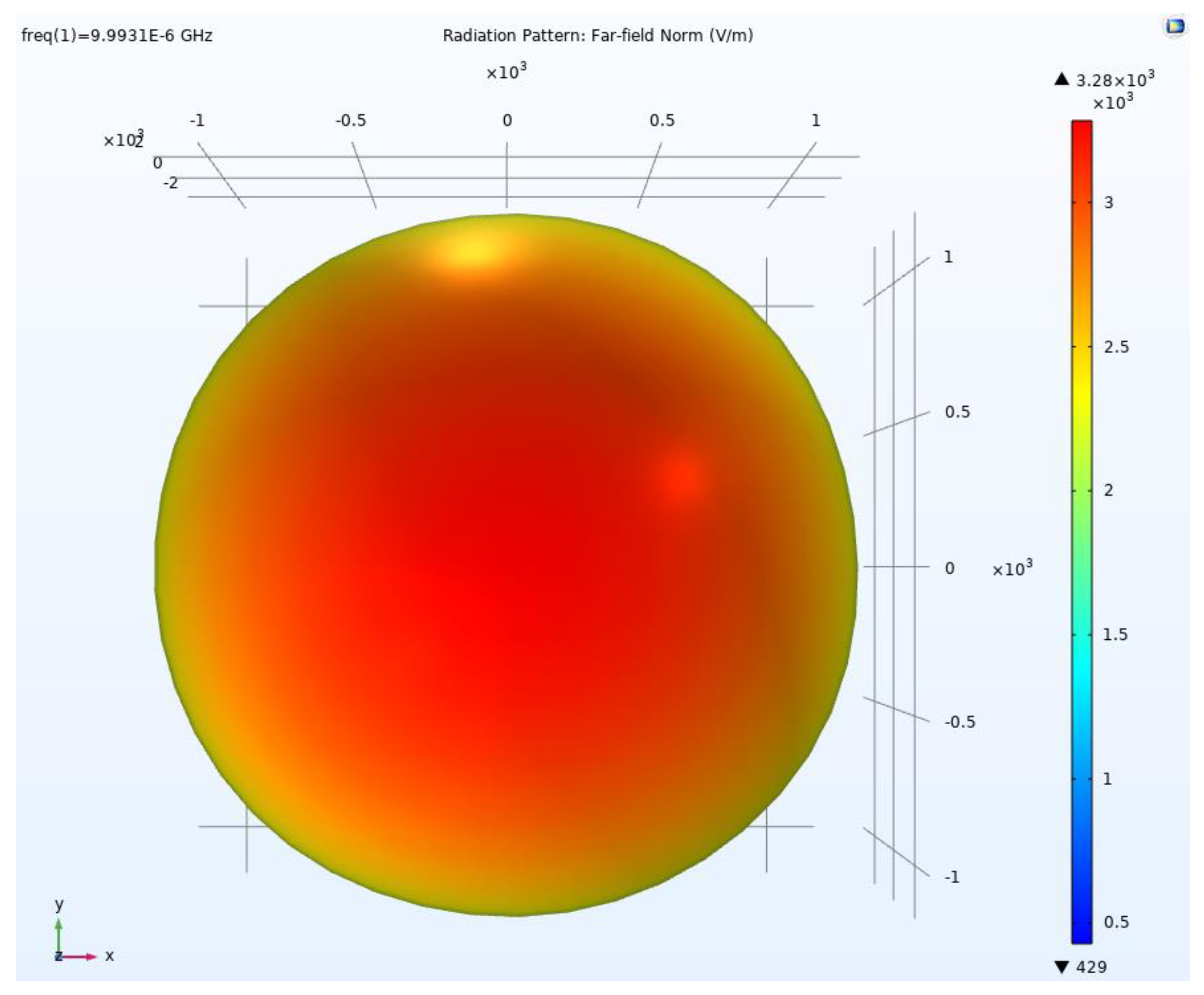
From the electric field distribution and electric field direction described in the previous section, it can be seen that, after the sequential rotation excitation, the linear polarization completed its conversion to circular polarization. A far-field model can be used to observe the process of formation of circular polarization more intuitively. Figure 11a shows the two-dimensional far-field pattern after circular polarization, while Figure 11b shows the three-dimensional far-field pattern.
Figure 11a,b show circular polarization patterns symmetrical to the MD array plane. It can be seen that the electromagnetic wave propagated in the circular polarization mode toward both sides. Figure 12 shows that the shape of the pattern seen from the propagation direction of the electromagnetic wave was circular.

5. Simulation of an SRE CP MD Antenna Array for Bi-Static Antenna GPR for Deep Exploration

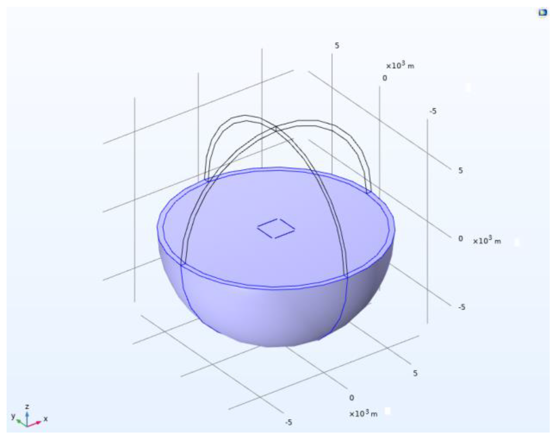
As shown in Figure 13, the SRE CP MD antenna array radiation source model was a sphere with a radius of 7.5 km, in which the upper half-space was air with ε r = 1 , μ r = 1 , and σ = 0 S m 1 and the lower half-space was soil with ε r = 3 , μ r = 1 , and σ = 0.01 S m 1 .
As further indicated by Figure 13, the SRE CP MD antenna array radiation source for the bi-static antenna GPR was placed on the ground. Four dipole antennas with arm lengths of 0.75 km were placed on four sides of a square area with a side length of 1.8 km. The feed phases and rotation angles of the four dipole antennas in the array were 0°, 90°, 180°, and 270°, respectively, and each dipole antenna needed to be excited with an equal amplitude (1000 V) at 10 KHz.

5.1. Electric Field Simulation of an SRE CP MD Antenna Array for Bi-Static Antenna GPR for Deep Exploration

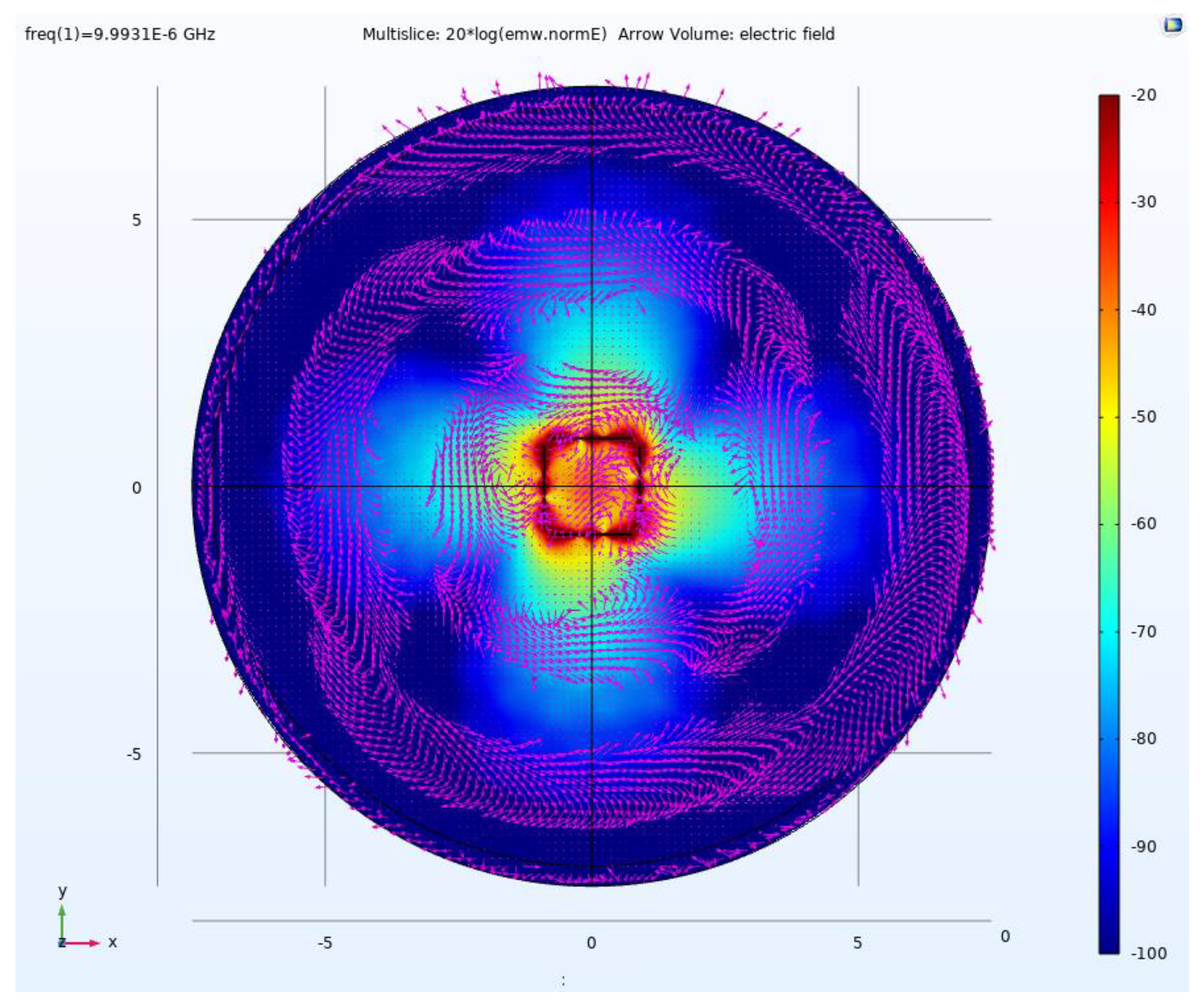
Figure 14, Figure 15, Figure 16 and Figure 17 show the electric field distribution and direction in the four sections of the lower half-space of the model—that is, the underground space—for the bi-static antenna GPR for deep exploration. Consistent with the situation in the homogeneous air domain, the electromagnetic wave in the half-space model also propagated in the Earth in a circularly polarized manner.

5.2. Far-Field Simulation of an SRE CP MD Antenna Array for Bi-Static Antenna GPR for Deep Exploration

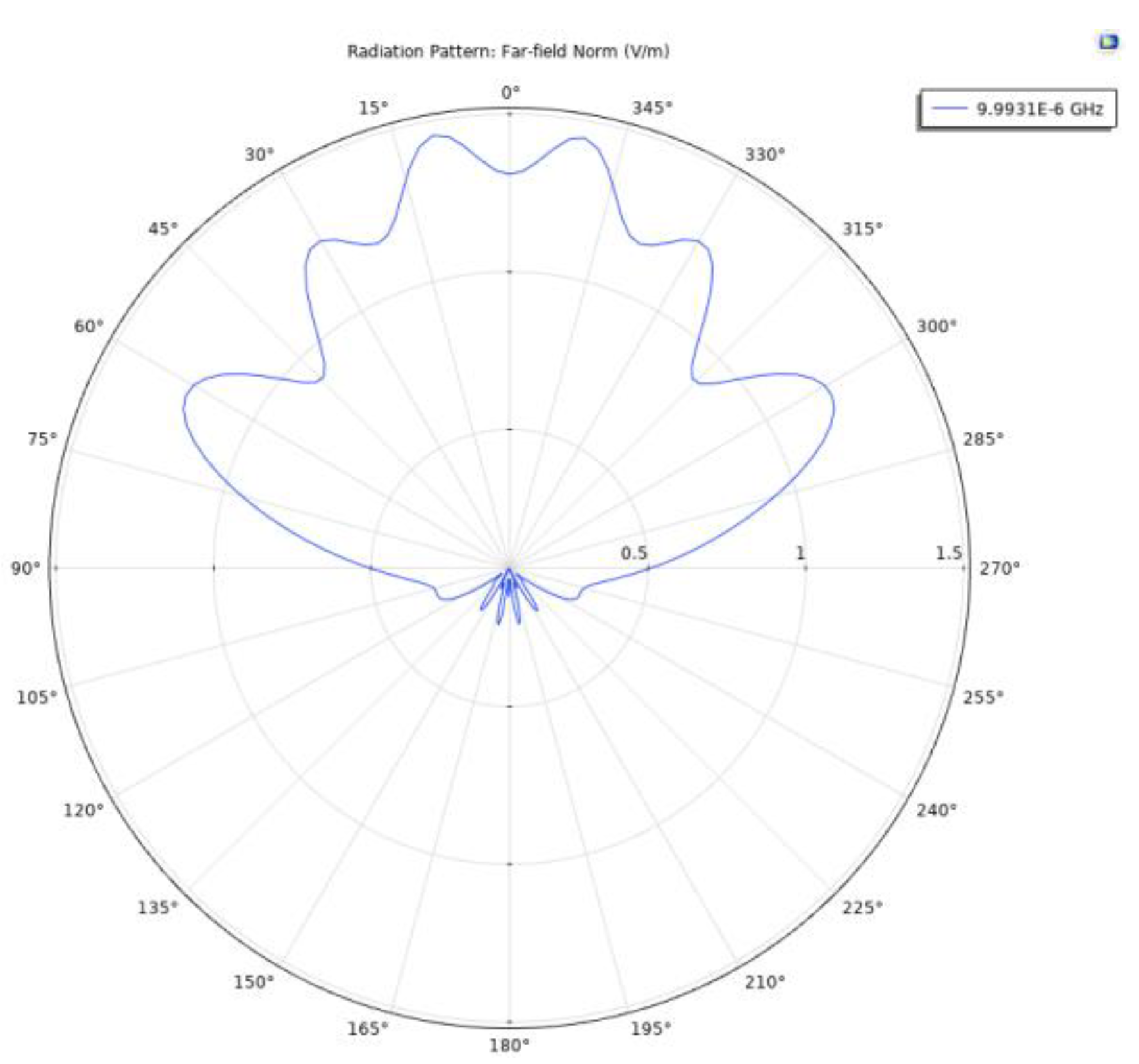
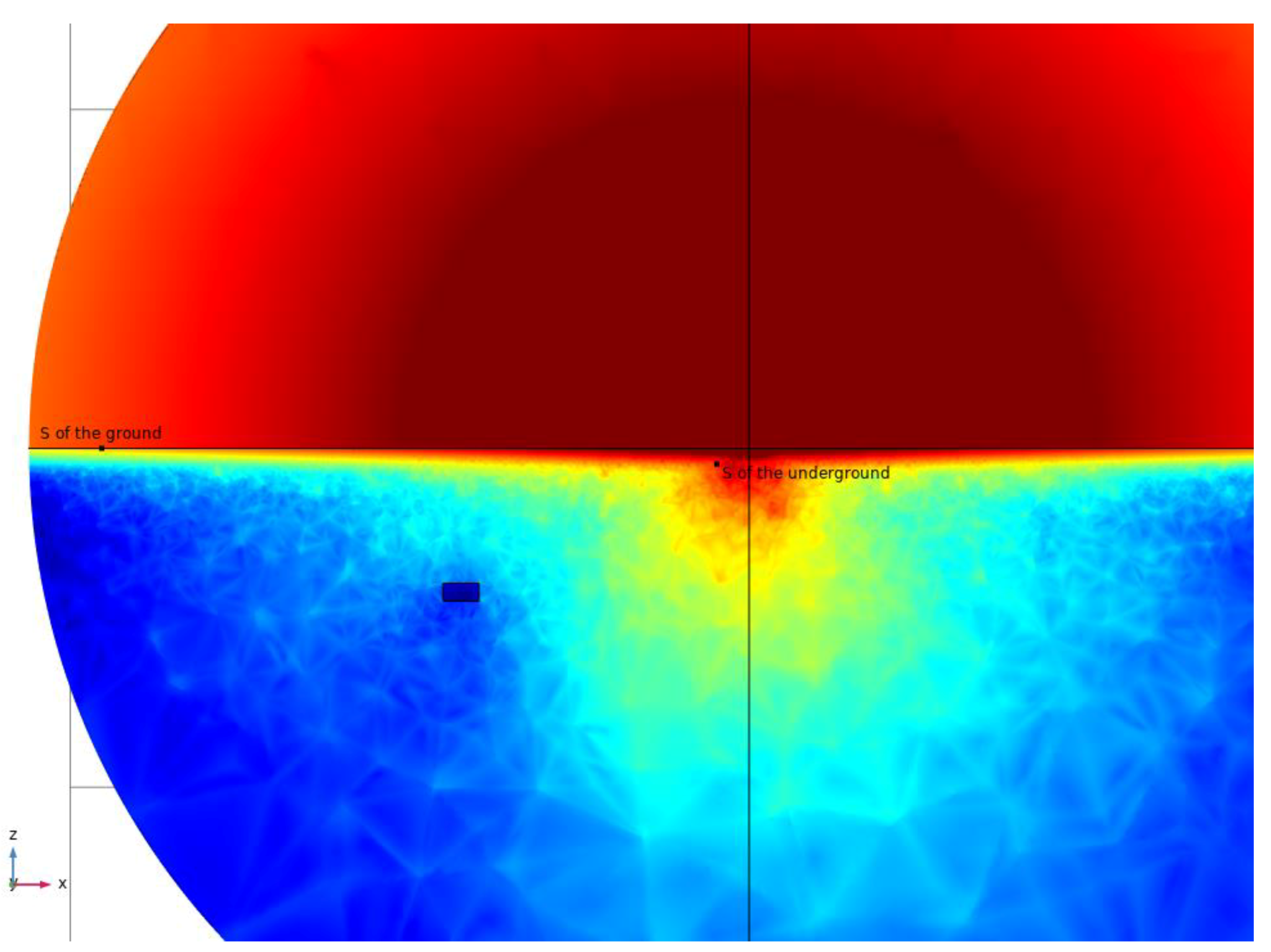
The upper half-space was the air domain, and the lower half-space was the Earth. As shown in Figure 18, most of the energy propagated toward the air domain, while the electromagnetic waves that penetrated the ground from the air mostly propagated to the far field in the form of side waves, which is consistent with the electromagnetic wave propagation mechanism analyzed in the previous section.
Figure 19 shows that there are two types of CP electromagnetic wave emitted by a radiation source: ground waves and underground waves. The two waves are similar to the waves with inconsistent phases produced by an MD array because the propagation speed on the ground is much greater than that underground. As is commonly known, the beam propagation direction is always perpendicular to the wave front, and, at a certain moment, the wave front of both waves will form into a synthetic wave front almost parallel to the ground. Consequently, a plane wave with perpendicular incidence will be formed. The plane wave will interact with underground anomalies and carry information to the receiving antenna on the surface.
As the receiving antenna was in the Ff, the wave front of the electromagnetic wave was almost parallel to the Earth after it reached the receiving antenna position. As shown in Figure 19, the electromagnetic wave re-radiated into the Earth at a vertical angle. This amount of energy should mainly be used for active remote sensing because the electromagnetic waves propagate in the form of circular polarization in this process, and CP electromagnetic waves have stronger penetration and lower attenuation. Moreover, this process can effectively address the problems caused by the multi-path effect and polarization mismatching, meaning that circular polarization has significant advantages over linear polarization.

6. Discussion

6.1. Comparison of SNRs of LP Dipole Antenna and CP MD Array for Bi-Static Antenna GPR for Deep Exploration

Compared to a traditional LP dipole antenna, an SRE CP MD array radiation source can reduce the significance of the problems caused by the multi-path effect and polarization mismatching, such as increased numbers of errors and greater signal attenuation during data reception and processing. Moreover, according to Equation (1), the stronger the electric field component on the y-axis and the magnetic field component on the x-axis are, the more accurate the calculation of the Cagniard resistivity is. As the horizontal linear polarization method is used in the conventional method, the component on the y-axis is significantly stronger than the component on the x-axis, meaning that there will be a large error in the calculation of the Cagniard resistivity. When the circular polarization method is used for transmission, once the electromagnetic wave reaches the receiving antenna, the electromagnetic field components in the x and y directions will have roughly the same orders of magnitude, meaning that the calculated resistivity will be more accurate. When the signal is measured at the receiving antenna, as the traditional GPR uses LP waves, a scalar measurement is used. The measurement line is parallel to the transmission antenna, and the electric field component along the direction of the transmission antenna ( E y ) and the magnetic field component perpendicular to the transmission antenna ( H x ) are measured, so only the underground one-dimensional geological structure can be distinguished. When using CP wave measurement, in order to better reflect the two-dimensional or three-dimensional underground geological structure, the vector method should be used for measurement, and five components ( E x , E y , H x , H y , H z ) should be measured.
In this study, we assumed that the power in both cases was 50 kW. Utilizing the premise of the same total power (TP), with the application of the SRE CP MD array, the energy received by the receiving antenna had a higher magnitude than that in the traditional method. Table 1 presents the excitation of two source modes with the same TP.
As shown in Table 2, when the two exploration methods were implemented with different receiving antenna points (the distance ranged from 5 km to 10 km, and the measurement was conducted every 1 km), the energy density time average (Wav) generated using the CP MD array was about five times that of the LP dipole antenna during the far-field observation.
According to the SNR calculation formula S = 10 lg P s P n , assuming that the effective Wav received by the receiving antenna is P S D when an LP dipole antenna is applied, the effective Wav received when a CP MD is applied is about 5 P S D , and the noise powers P n of both are equal. As can be seen from Table 2, we can then obtain
S S D = 10 lg P S D P n
S M D = 10 lg 5 P S D P n
S M D S S D = 10 lg 5 P S D P n 10 lg P S D P n = 10 lg 5 7 d B
where S S D represents the SNR received by the receiving antenna when an LP dipole antenna is applied, and S M D represents the SNR received by the receiving antenna when a CP MD array is applied.
By subtracting Equation (12) from Equation (11), we obtain Equation (13); the difference between the SNR values is about 7 dB. In other words, the SNR of the CP MD array is 7 dB better than that of the conventional method, which has obvious advantages when dealing with complex noise environments in the field.

6.2. Comparison of Remote Sensing Depths of the Large-Aperture CP MD Array and Small-Size LP Dipole Antenna for Bi-Static Antenna GPR for Deep Exploration

When a bi-static antenna GPR was used for deep exploration in a previous study, it could be seen that, for the receiving antenna, the electromagnetic waves vertically shot into the Earth in the form of plane-like waves. When the electromagnetic wave propagates in the medium, there is a skin effect, and the higher the frequency of the electromagnetic wave is, the more obvious the skin effect. This can be seen in Equation (14):
δ = 2 ρ ω μ = 2 ω μ σ = 2 2 π f μ σ
where δ represents the remote sensing depth; ω represents the angular frequency; μ represents the permeability; ρ represents the resistivity; σ represents the conductivity; and f represents the electromagnetic field frequency.
The low-frequency rate of conventional GPR remote sensing is about 1 MHz, while the frequency of an electromagnetic field can be as low as 10 KHz with the application of a CP MD array.
δ A R S δ c o n v e n t i o n a l = 1 f A R S 1 f c o n v e n t i o n a l = f c o n v e n t i o n a l f A R S = 10
According to Equation (15), the remote sensing depth is ten times deeper with the application of a large-aperture CP MD array than that achieved with conventional methods.

7. Conclusions

In this paper, a novel SRE CP MD array for a bi-static antenna GPR for deep exploration was proposed. We used a large-aperture CP MD array instead of a small-size LP dipole antenna. The analysis and simulation results demonstrated that, comparing circular polarization and linear polarization with the premise of the same transmitting power, the SRE CP multiple-dipole antenna array radiation source achieved a significant enhancement (about 7 dB) in the signal-to-noise ratio (SNR) as the radiant energy was collected at the receiving antenna. More importantly, by reducing the exploration frequency to 10 KHz, the exploration depth could also be greatly increased by about tenfold.
First, the principle for SRE circular polarization was presented. A dipole antenna, an SRE CP MD antenna array, and an SRE CP MD antenna array radiation source for a bi-static antenna GPR for deep exploration were simulated. Then, on the basis of the calculations and the analyses of the SRE CP MD antenna array, several numerical models for the implementation of an SRE CP MD antenna array radiation source with analytical solutions were built. Finally, the effects of the SRE CP MD antenna array radiation source were compared with those of conventional methods. The theoretical analysis and simulation results were all consistent, verifying the correctness and effectiveness of using the proposed SRE CP MD antenna array radiation source in bi-static antenna GPRs for deep exploration.

Author Contributions

Conceptualization, H.F.; Methodology, H.F.; Visualization, Q.T.; Project administration, Y.Z.; Validation, X.W.; Investigation, H.M. All authors have read and agreed to the published version of the manuscript.

Funding

This work was supported by the Beijing Municipal Natural Science Foundation (no. 3214058).

Data Availability Statement

Not applicable.

Acknowledgments

All of the authors thank the referees, editors, and officers of Remote Sensing for their valuable suggestions and help.

Conflicts of Interest

The authors declare no conflict of interest.

Abbreviations

GPRGround-penetrating radar
LPLinear polarized
CPCircular polarized
MDMultiple-dipole
SRESequential rotationally excited
SNRSignal to noise ratio
MIMOMultiple-input multiple-output
TPTransmitting power
WavEnergy density time average

References

  1. Cui, F.; Bao, J.; Cao, Z.; Li, L.; Zheng, Q. Soil hydraulic parameters estimation using ground penetrating radar data via ensemble smoother with multiple data assimilation. J. Hydrol. 2020, 583, 124552. [Google Scholar] [CrossRef]
  2. Léger, E.; Saintenoy, A.; Coquet, Y. Hydrodynamic parameters of a sandy soil determined by ground-penetrating radar inside a single ring infiltrometer. Water Resour. Res. 2014, 50, 5459–5474. [Google Scholar] [CrossRef] [Green Version]
  3. Klotzsche, A.; Jonard, F.; Looms, M.C.; van der Kruk, J.; Huisman, J.A. Measuring Soil Water Content with Ground Penetrating Radar: A Decade of Progress. Vadose Zone J. 2018, 17, 180052. [Google Scholar] [CrossRef] [Green Version]
  4. Yu, Y.; Weihermüller, L.; Klotzsche, A.; Lärm, L.; Vereecken, H.; Huisman, J.A. Sequential and coupled inversion of horizontal borehole ground penetrating radar data to estimate soil hydraulic properties at the field scale. J. Hydrol. 2021, 596, 126010. [Google Scholar] [CrossRef]
  5. Jaumann, S.; Roth, K. Soil hydraulic material properties and layered architecture from time-lapse GPR. Hydrol. Earth Syst. Sci. 2018, 22, 2551–2573. [Google Scholar] [CrossRef] [Green Version]
  6. Lambot, S.; Slob, E.C.; Bosch, I.v.d.; Stockbroeckx, B.; Vanclooster, M. Modeling of ground-penetrating Radar for accurate characterization of subsurface electric properties. IEEE Trans. Geosci. Remote Sens. 2004, 42, 2555–2568. [Google Scholar] [CrossRef]
  7. Davis, J.L.; Annan, A.P. Ground-penetrating radar for high-resolution mapping of soil and rock stratigraphy1. Geophys. Prospect. 1989, 37, 531–551. [Google Scholar] [CrossRef]
  8. Tran, A.P.; Bogaert, P.; Wiaux, F.; Vanclooster, M.; Lambot, S. High-resolution space–time quantification of soil moisture along a hillslope using joint analysis of ground penetrating radar and frequency domain reflectometry data. J. Hydrol. 2015, 523, 252–261. [Google Scholar] [CrossRef]
  9. Yu, Y.; Huisman, J.A.; Klotzsche, A.; Vereecken, H.; Weihermüller, L. Coupled full-waveform inversion of horizontal borehole ground penetrating radar data to estimate soil hydraulic parameters: A synthetic study. J. Hydrol. 2022, 610, 127817. [Google Scholar] [CrossRef]
  10. Feng, X.; Ren, Q.; Liu, C.; Zhang, X. Joint acoustic full-waveform inversion of crosshole seismic and ground-penetrating radar data in the frequency domain. Geophysics 2017, 82, H41–H56. [Google Scholar] [CrossRef]
  11. Serbin, G.; Or, D. Ground-penetrating radar measurement of soil water content dynamics using a suspended horn antenna. IEEE Trans. Geosci. Remote Sens. 2004, 42, 1695–1705. [Google Scholar] [CrossRef]
  12. Zeng, Z.F.; Li, J.; Huang, L.; Feng, X.; Liu, F.S. Improving Target Detection Accuracy Based on Multi polarization MIMO GPR. IEEE Trans. Geosci. Remote Sens. 2015, 53, 15–24. [Google Scholar] [CrossRef]
  13. Xu, X.L. Development of Vehicle Mounted Ground Penetrating Radar System and Experimental Research on Its Application; China University of Mining and Technology: Beijing, China, 2013. [Google Scholar]
  14. Lai, J.L.; Xu, Y.; Zhang, X.P.; Xiao, L.; Yan, Q.; Meng, X.; Zhou, B.; Dong, Z.H.; Zhao, D. Comparison of Dielectric Properties and Structure of Lunar Regolith at Chang’e-3 and Chang’e-4 Landing Sites Revealed by Ground-Penetrating Radar. Geophys. Res. Lett. 2019, 46, 12783–12793. [Google Scholar] [CrossRef]
  15. Bano, M. Modelling of GPR wave for lossy media obeying a complex power law of frequency for dielectric permittivity. Geophys. Prospect. 2004, 52, 11–26. [Google Scholar] [CrossRef] [Green Version]
  16. Brosten, T.R.; Day-Lewis, F.D.; Schultz, G.M.; Curtis, G.P.; Lane, J.W. Inversion of multi-frequency electromagnetic induction data for 3D characterization of hydraulic conductivity. J. Appl. Geophys. 2011, 73, 323–335. [Google Scholar] [CrossRef]
  17. Bano, M.; Tsend-Ayush, N.; Schlupp, A.; Munkhuu, U. Ground-Penetrating Radar Imaging of Near-Surface Deformation along the Songino Active Fault in the Vicinity of Ulaanbaatar, Mongolia. Appl. Sci. 2021, 11, 8242. [Google Scholar] [CrossRef]
  18. Lavoué, F.; Brossier, R.; Métivier, L.; Garambois, S.; Virieux, J. Two-dimensional permittivity and conductivity imaging by full waveform inversion of multi offset GPR data: A frequency-domain quasi-Newton approach. Geophys. J. Int. 2014, 197, 248–268. [Google Scholar] [CrossRef] [Green Version]
  19. Busch, S.; van der Kruk, J.; Bikowski, J.; Vereecken, H. Quantitative conductivity and permittivity estimation using full-waveform inversion of on-ground GPR data. Geophysics 2012, 77, H79–H91. [Google Scholar] [CrossRef]
  20. Jin, R.; Lee, K.S. Investigation of Forest Fire Characteristics in North Korea Using Remote Sensing Data and GIS. Remote Sens. 2022, 14, 5836. [Google Scholar] [CrossRef]
  21. Shlykov, A.A.; Saraev, A.K. Wave effects in the field of a high frequency horizontal electric dipole. Izv.-Phys. Solid Earth 2014, 50, 249–262. [Google Scholar] [CrossRef]
  22. Unsworth, M.J.; Travis, B.J.; Chave, A.D. Electromagnetic induction by a finite electric dipole source over a 2D earth. Geophysics 1993, 58, 198–318. [Google Scholar] [CrossRef]
  23. Hobbs, B.; Ziolkowski, A.; Wright, D. Multi-Transient Electromagnetics (MTEM)-controlled source equipment for subsurface resistivity investigation. 18th IAGA WG 2006, 1, 17–23. [Google Scholar]
  24. Kuznetzov, A.N. Distorting effects during electromagnetic sounding of horizontally non-uniform media using an artificial field source. Earth Physics. 1982, 18, 130–137. [Google Scholar]
  25. Wang, X.X.; Di, Q.Y.; Xu, C. Characteristics of Multiple Dipole Sources and Tensor Measurement in CSAMT. J. Geophys. 2014, 57, 651–661. [Google Scholar]
  26. Radzevicius, S.J.; Daniels, J.J.; Guy, E.D.; Vendl, M.A. Significance of crossed-dipole antennas for high noise environments. In 13th EEGS Symposium on the Application of Geophysics to Engineering and Environmental Problems; European Association of Geoscientists & Engineers: Houten, The Netherlands, 2000; pp. 407–413. [Google Scholar] [CrossRef]
  27. Liu, L.; Wang, C. Two-dimensional DOA estimation based on polarization sensitive array and uniform linear array. J. Electron. Inf. Technol. 2019, 41, 2350–2357. [Google Scholar]
  28. Huang, Y.; Barkat, M. Near-field multiple source localization by passive sensor array. IEEE Trans. Antennas Propag. 1991, 39, 968–975. [Google Scholar] [CrossRef]
  29. Ma, H.; Tao, H.; Xie, J. Mixed far-field and near-field source localization using a linear tripole array. IEEE Wirel. Commun. Lett. 2020, 9, 889–892. [Google Scholar] [CrossRef]
  30. Ma, H.; Tao, H.; Kang, H. Mixed far-field and near-field source localization using a linear electromagnetic-vector-sensor arraywith gain/phase uncertainties. IEEE Access 2021, 9, 132412–132428. [Google Scholar] [CrossRef]
  31. Zhao, L.; Tao, H.; Chen, W.; Song, D. Maneuvering target detection based on subspace subaperture joint coherent integration. Remote Sens. 2021, 13, 1948. [Google Scholar] [CrossRef]
  32. He, J.; Ahmad, M.O.; Swamy, M.N.S. Near-field localization of partially polarized sources with a cross-dipole array. IEEE Trans. Aerosp. Electron. Syst. 2013, 49, 857–870. [Google Scholar] [CrossRef]
  33. Yuan, X. Coherent sources direction finding and polarization estimation with various compositions of spatially spread polarized antenna arrays. IEEE Signal Process. 2014, 102, 265–281. [Google Scholar] [CrossRef] [Green Version]
  34. Zhao, Y.; Zhang, Q.; Tang, B. Frequency diversity array MIMO track-before-detect in coherent repeated interference. IEICE Trans. Fundam. Electronics. Commun. Comput. Sci. 2018, 10, 1703–1707. [Google Scholar] [CrossRef]
  35. He, J.; Li, L.; Shu, T. Near-field parameter estimation for polarized source using spatial amplitude ratio. IEEE Commun. Lett. 2020, 24, 1961–1965. [Google Scholar] [CrossRef]
  36. Sedighi, S.; Rao, B.; Ottersten, B. An asymptotically efficient weighted least squares estimator for co-array-based DOA Estimation. IEEE Trans. Signal Process. 2020, 68, 589–604. [Google Scholar] [CrossRef] [Green Version]
  37. Fan, H.F.; Zhang, Y.M.; Wang, X.H. An Asymmetric Beamforming Method Based on Arithmetic Phase Difference Weighting in CSAMT. Symmetry 2022, 14, 2374. [Google Scholar] [CrossRef]
  38. Lehmann, F.; Boerner, D.E.; Holliger, K.; Green, A.G. Multicomponent georadar data: Some important implications for data acquisition and processing. Geophysics 2000, 65, 1542–1552. [Google Scholar] [CrossRef]
Figure 1. Electromagnetic wave transmission path.
Remotesensing 15 01134 g001
Figure 2. Linear radiation source.
Remotesensing 15 01134 g002
Figure 3. N-element linear array.
Remotesensing 15 01134 g003
Figure 4. Structure of the dipole antenna.
Remotesensing 15 01134 g004
Figure 5. (a) Electric field distribution and (b) direction of dipole antenna.
Remotesensing 15 01134 g005
Figure 6. Structure of CP MD antenna array.
Remotesensing 15 01134 g006
Figure 7. Electric field distribution on the MD plane.
Remotesensing 15 01134 g007
Figure 8. Electric field distribution and direction on MD plane.
Remotesensing 15 01134 g008
Figure 9. Electric field distribution and direction on the plane 10 km above the MD plane.
Remotesensing 15 01134 g009
Figure 10. Electric field distribution and direction on the plane 20 km above the MD plane.
Remotesensing 15 01134 g010
Figure 11. (a) Two-dimensional far-field pattern after circular polarization. (b) Three-dimensional far-field pattern after circular polarization.
Remotesensing 15 01134 g011
Figure 12. Pattern shape seen from the direction of electromagnetic wave propagation.
Remotesensing 15 01134 g012
Figure 13. The SRE CP MD antenna array radiation source model.
Remotesensing 15 01134 g013
Figure 14. Electric field distribution and direction on the MD plane.
Remotesensing 15 01134 g014
Figure 15. Electric field distribution and direction on the plane 5 km below the MD plane.
Remotesensing 15 01134 g015
Figure 16. Electric field distribution and direction on the plane 10 km below the MD plane.
Remotesensing 15 01134 g016
Figure 17. Electric field distribution and direction on the plane 20 km below the MD plane.
Remotesensing 15 01134 g017
Figure 18. Two-dimensional far-field pattern for the H-plane.
Remotesensing 15 01134 g018
Figure 19. The plane wave principle for a bi-static antenna GPR for deep exploration.
Remotesensing 15 01134 g019
Table 1. Excitation of two source modes with the same TP.
Source ModeVoltage (V)Current (A)Phase (deg)Total Power (kW)
CP MD arrayDipole antenna1 25012.5050
Dipole antenna2 25012.590
Dipole antenna3 25012.5180
Dipole antenna4 25012.5270
LP dipole antenna100050050
Table 2. Comparison of the Wav normalized according to the TP.
Position (x, y, z)Wav of CP MD ArrayWav of LP Dipole Antenna
(10,000, 0, 0)2.03 × 10⁻²³ J/m33.86 × 10−24 J/m3
(9000, 0, 0)3.59 × 10⁻²³ J/m37.22 × 10−24 J/m3
(8000, 0, 0)5.23 × 10⁻²³ J/m31.06 × 10−23 J/m3
(7000, 0, 0)6.93 × 10⁻²³ J/m31.32 × 10−23 J/m3
(6000, 0, 0)8.55 × 10⁻²³ J/m31.69 × 10−23 J/m3
(5000, 0, 0)1.39 × 10⁻²² J/m32.75 × 10−23 J/m3
Disclaimer/Publisher’s Note: The statements, opinions and data contained in all publications are solely those of the individual author(s) and contributor(s) and not of MDPI and/or the editor(s). MDPI and/or the editor(s) disclaim responsibility for any injury to people or property resulting from any ideas, methods, instructions or products referred to in the content.