1. Introduction
The concept of autonomous navigation is expected to find large applications in the near feature, revolutionizing the conventional approach of maritime navigation. Maritime Autonomous Surface Ships (MASSs) refer to cutting-edge vessel ships that are equipped with advanced technologies exploiting the potential of artificial intelligence together with sensors and communication systems, enabling them to navigate and carry out various tasks at sea autonomously [
1].
The driving force behind the adoption of autonomous commercial ships arises from the aspiration to improve safety, cut expenses, and minimize environmental issues associated with shipping operations [
2]. Another study presented in [
3] has assessed and quantified the positive impact on energy savings and environmental pollution prevention of adopting autonomous navigation systems by analyzing hundreds of conventional ships and their energy consumption and environmental impact.
In recent years, the developers of Digital Twin (DT) technology within the maritime industry have shown a growing interest in the autonomous navigation field due to its potential, among others, to enhance real-time monitoring of vessel performances and aid in decision-making processes to maximize operational efficiency [
4,
5].
The implementation of cutting-edge models such as DTs and their integration with system automation or other technologies aimed at achieving autonomous navigation all necessitate a substantial exchange of data between the vessel and the land-based systems. One potential solution for data transmission could involve conducting ship-to-land data exchange via low-orbit satellites (LOSs).
Among the systems that can be considered for optical satellite–ship communication, the main ones are Free-Space Optical Communication (FSO) [
6], laser communication [
7] and Hybrid Systems that combine different technologies, such as via the integration of optical communication systems with radio frequencies. In the case of FSO-type communication, the systems are susceptible to atmospheric conditions and alignment issues due to motion, vibration or pointing errors [
8].
Autonomous shipping requires a high level of security and the exchange of huge volumes of data between ships and satellites. Quantum laser communication presents a possible approach for the realization of autonomous navigation technology due to its lower sensitivity to adverse weather conditions, but it requires high pointing accuracy [
9].
In the context of laser communication between the ground and satellites, it is crucial to create a direct line of sight between the ground-based station and the satellite in orbit. This is necessary to guarantee the reliability of the system. Given that the optical beam is highly focused, precise acquisition, tracking and pointing (ATP) systems are crucial, particularly for long-distance communication. “Pointing” is the term used to describe the action of aligning the transmitter with the receiver’s Field of View (FOV), while “tracking” refers to the track of the satellite once has been pointed [
10].
Optical satellite communication is closely influenced by the presence of errors that affect pointing and, thus, establishing a secure connection. The study reported in [
11] identifies, among others, geometric errors (manufacturing errors), installation errors and attitude errors as the major sources of error that influence the satellite pointing of an optical communication terminal and introduces a mathematical model for their reduction.
Other studies such as [
12,
13] have used filters and algorithms with the aim of improving the accuracy of the LOS’s pointing, reducing the size of the field of uncertainty, and providing reference and guidance for the design of space optical communication systems.
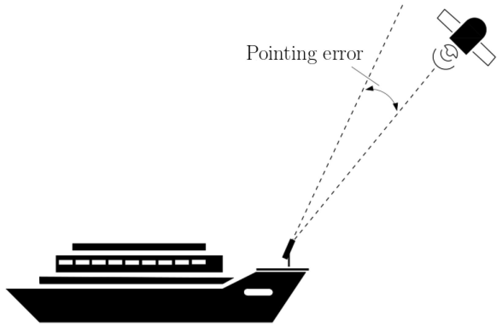
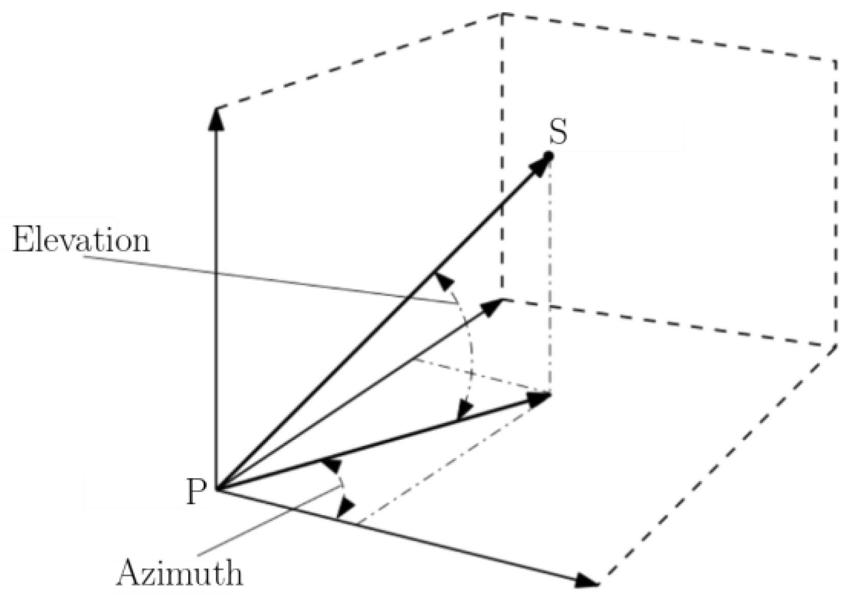
In this study, an ATP model with two degrees of freedom (DoFs) is presented and the pointing error (
Figure 1), i.e., the difference between the satellite position and the pointed target, is analyzed in order to verify the possibility of enabling data exchange between ships and LOS satellites. The considered model accounts for ship motions and the coordinates of low-orbit satellites, taking into consideration the acquisition errors associated with ship motions and satellite coordinates during the acquisition phase. The minimum pointing accuracy requested by the optical system is 100 µrad to reach the satellite’s locking area. Achieving a high pointing accuracy for shipborne ATP systems during the initial pointing process is challenging. These challenges arise from factors like random and sharp waggling along with the sea, especially in several sea conditions. The study introduces an innovative methodology to improve the pointing accuracy to higher than 100 µrad through the application of celestial vault-scanning strategies. The results obtained are used to size the optical system and verify the feasibility of the scanning strategies through the piezoelectric components within the optical system.
2. Methodology
This chapter presents the methodology employed to assess the pointing accuracy of the ATP system, during the pointing phase, with the objective of evaluating the feasibility of facilitating ship-to-satellite optical communication. Once the satellite has been pointed, the system is able to track its position (tracking phase), so the analysis will be focused on the pointing phase. This section introduces the definition of the model along with satellite coordinates and ship motions. The kinematic definition of the model together with the control diagram to evaluate the pointing accuracy is presented, and then the last subsection introduces methodologies to reduce pointing error and evaluate the reliability of the system.
2.1. Model
The ATP system encompasses two principal entities: Body and Pointer. The model considered for the analysis comprehends the ground element in order to introduce the ship deck swing that is the consequence of the presence of ship motions (
Figure 2). The considered ATP system mass is about 5 kg, and the two DoFs of the system include the Body rotation around the
Z-axis (azimuth DoF) and the Pointer rotation (elevation DoF) around the
Y-axis.
2.2. Satellite’s Coordinates
The satellite’s coordinates for the considered low-orbit satellite are given in the Earth-centered, Earth-fixed coordinate (ECEF) system. The Earth-centered, Earth-fixed coordinate system (known also as the geocentric coordinate system) is a Cartesian spatial reference framework for representing, e.g., satellite coordinates referring to Earth’s center of mass [
14].
The considered satellite has an orbital period of approximately 180 min with an average speed of 4.2 km/s, and maintains an average distance from Earth of 631.7 km.
The considered errors in the satellite’s coordinates due to acquisition and orbital propagation errors are taken into account [
15], and the absolute values considered for every direction are listed in
Table 1.
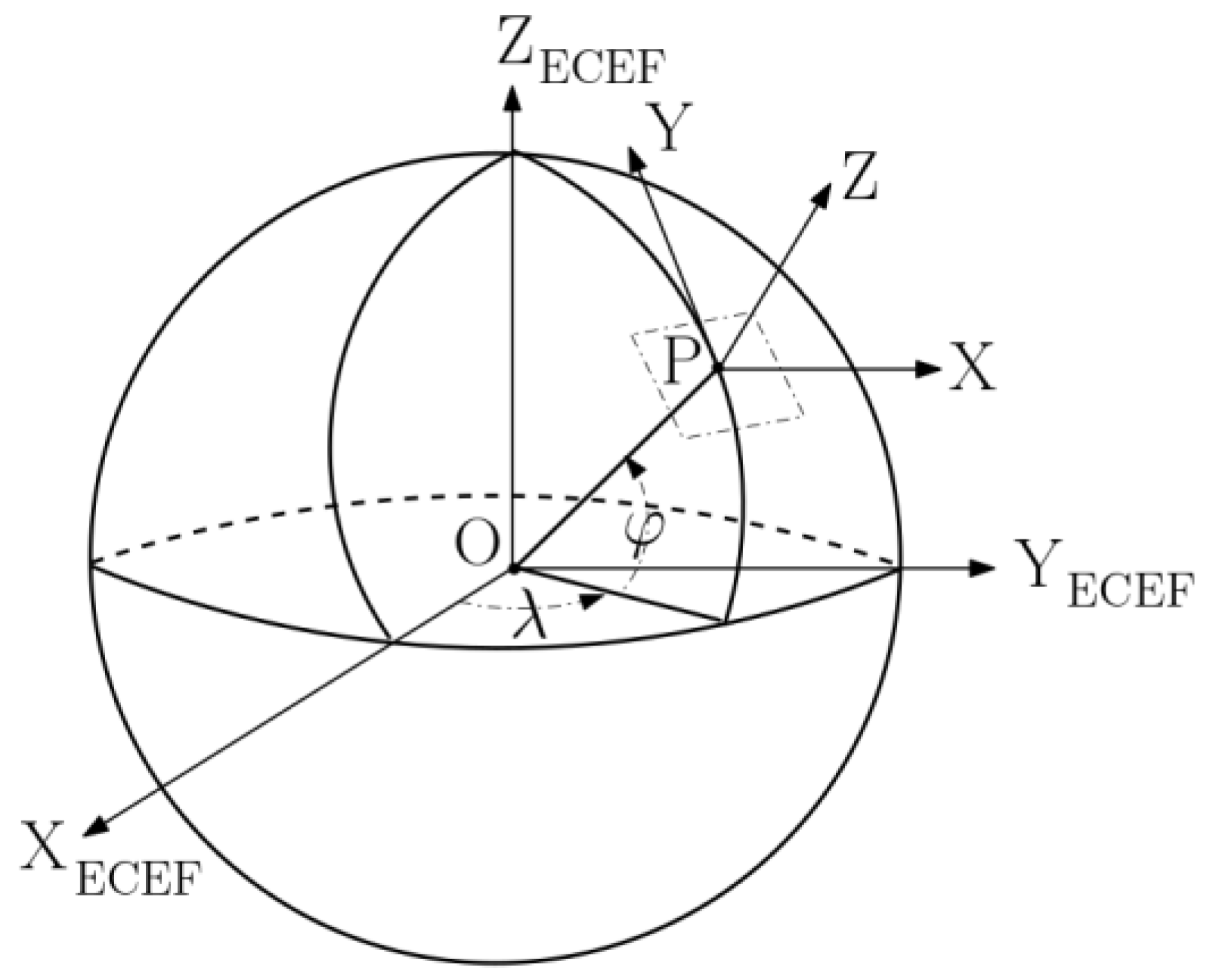
In this context, the given satellite’s ECEF coordinates are transformed into the satellite’s coordinates in the East-North-Up (ENU) reference system; the reference frames are depicted in
Figure 3. The origin of the ENU reference frame results in ships’ positions (commonly determined by a Global Navigation Satellite System (GNSS) [
16]) and the two axes,
Y and
X, are tangential to Earth’s surface at that point [
17]. This coordinate transformation is applied to convey the satellite’s position with respect to the ATP system’s position on Earth.
The transformation between satellite ECEF and ENU coordinates is presented in [
18]; below, the equations will be presented considering the following application scenario.
where, in this case,
φ,
λ and
h are, respectively, the latitude, longitude and altitude of the considered ground point.
Assuming that P represents the geodetic coordinates of the ship’s position:
it is possible to determine the ship’s coordinates in the ECEF reference frame:
by following the geodetic-to-ECEF coordinates’ transformation presented in [
19].
The satellite’s coordinates in the ECEF reference frame can be expressed as in Equation (4).
The satellite coordinates transformation from the ECEF reference frame, and the ENU reference frame can be expressed as follows:
in which X, Y and Z are the satellite’s coordinates in the ENU reference frame as defined in Equation (6).
Considering the ENU reference frame as the Earth reference frame, the transformation matrix from Earth to satellite
can be expressed through Equation (6).
2.3. Ship Motions
The vessel under consideration in the study has an overall length of approximately 230 m and a breadth of about 32 m. Therefore, in the analysis, the effects of wind and sea currents can be considered negligible compared to the effects of waves.
Since the ATP system is placed on the ship’s deck, system operations could be influenced by ship motions that result in system oscillations in magnitude depending on the navigation conditions.
While the effects arising from the angular motions of the ship are the most influential, translational motions have a lesser impact on the pointing system, introducing a very insignificant error, and will not be considered in the analysis.
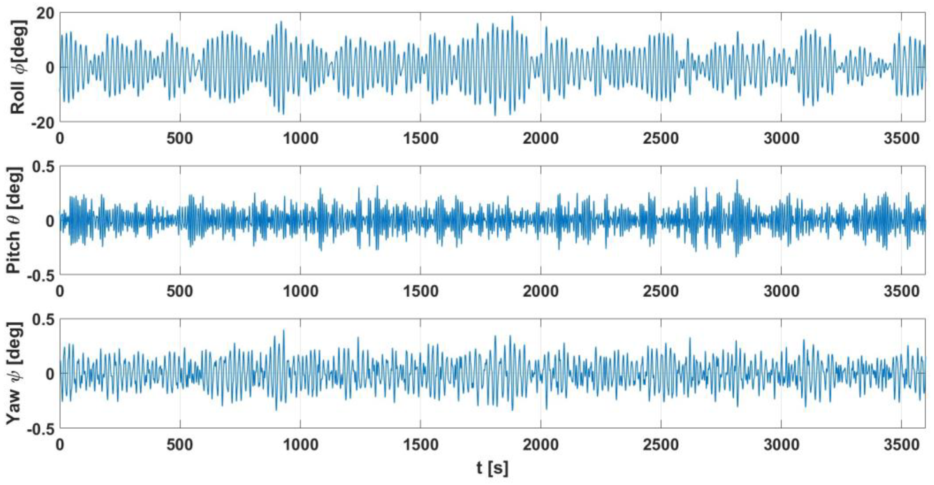
In the model, ship motions are considered as Euler angular displacement quantities of the ship’s deck with the roll–pitch–yaw convention presented in
Figure 4.
Several sea conditions about vessel type considered for the investigation have been previous analyzed in [
20,
21,
22]. This work focuses on the environmental conditions from [
23,
24], considering long-crested waves and assuming a Bretschneider spectrum (
Table 2). Ship motions have been predicted by a linear seakeeping approach that, for example, was also reported in [
25,
26].
In
Table 2, the acronym SWH refers to Significant Wave Height, which is defined as four times the standard deviation of the surface elevation [
27], while Heading is the relative angle between the direction of the vessel and the propagation direction of the waves.
As introduced, ship motions are expressed as the Euler angular displacement of the ship deck;
Figure 5 presents an overview of ship motions.
The acquisition phase of ship motions is affected by GPS/INS unit attitude measurement accuracy. Following the study presented in [
28], it is possible to define the Euler’s angular error quantities (
Table 3):
And then, transpose it to the azimuth and elevation DoFs of the ATP system (
Table 4).
2.4. Model Kinematic and Dynamic Definition
The model introduced at the beginning of the chapter was imported into the MSC Adams environment, and its kinematics has been defined. Referring to
Figure 2, the rotation of the ATP Body around the
Z-axis (azimuth DoF) has been inserted as a rotational joint, which was also employed to specify the ATP Pointer’s rotation (elevation DoF) around the
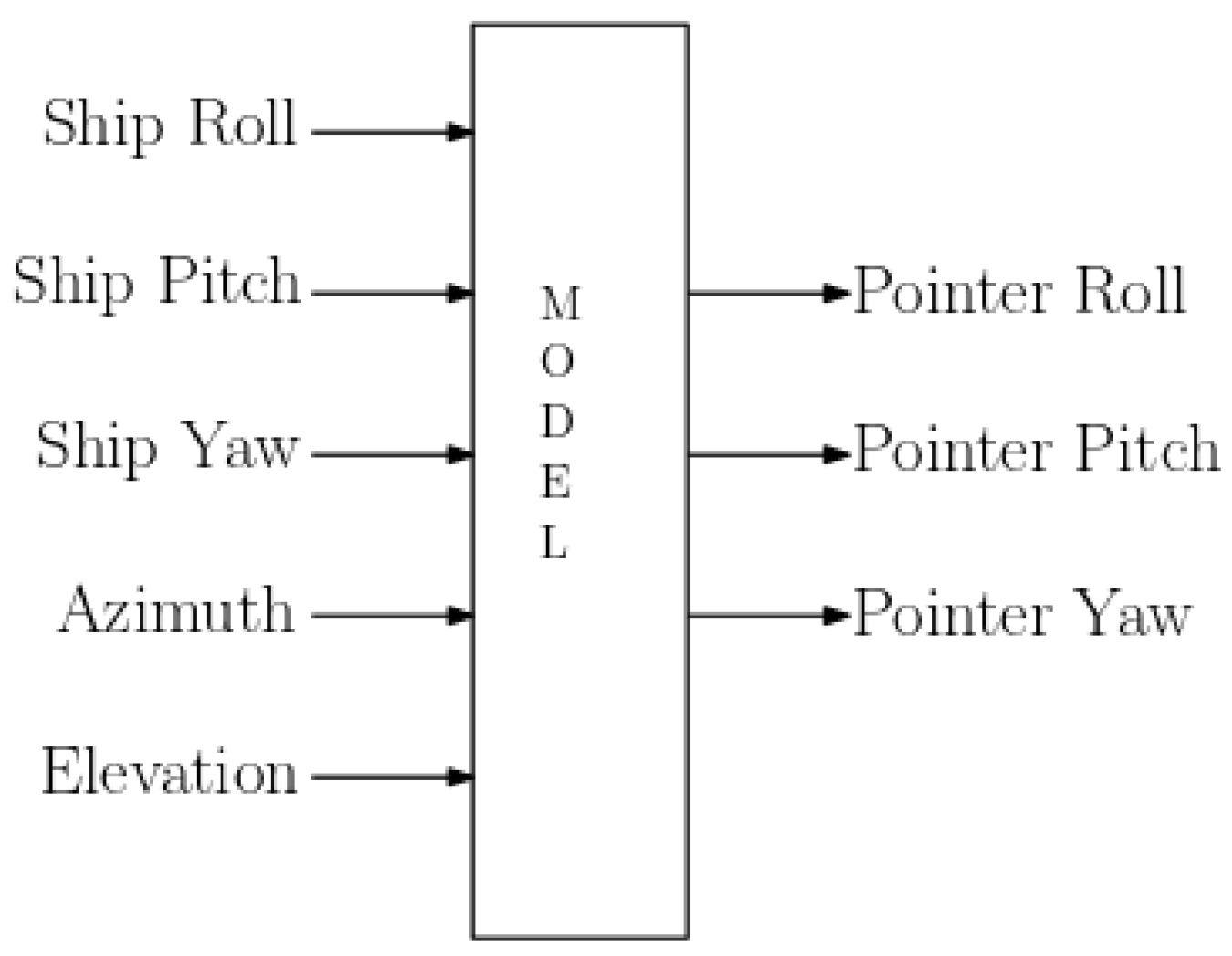
Y-axis. The respective torques have been added to these two joints and defined as system variables. The ATP system displacements caused by ship motions have been introduced through a spherical joint placed at the base of the ship deck segment and angular displacements have been defined as system variables.
At the output, the displacement in terms of Euler angles of the Pointer was measured and it was used to measure the accuracy during the pointing operation phase. The ADAMS model with input and output quantities is presented in
Figure 6.
2.5. Control System Diagram
The model was next imported into a MATLAB–Simulink environment to facilitate an ADAMS–Simulink co-simulation. The model was exported from ADAMS through the plant-export tool and integrated into Simulink as a block, featuring input and output variables as outlined in the preceding sub-chapter. A closed-loop control system has been defined (
Figure 7,
Table 5), with a specific section of the diagram focused on assessing pointing accuracy.
The closed control loop incorporates satellite coordinates (transformed from ECEF to ENU reference frame as introduced in Equations (1)–(7)), ship motions, and the previously introduced errors referred to, satellite coordinates and ship motions (
Table 1 and
Table 4), as inputs. Both types of errors are introduced as random errors in the intervals considered. The satellite coordinates with the added errors are multiplied with the rotation matrix from the ENU reference frame to the Pointer reference frame (
Figure 8).
This multiplication allows us to express the coordinates of the satellite in the Pointer reference frame.
The azimuth–elevation function (
Figure 9) calculates the satellite’s displacement in terms of azimuth and elevation and accounts for the error quantities resulting from the acquisition of ship motions presented in
Table 4.
Azimuth and elevation are calculated as presented in Equations (8) and (9):
considering S the position of the satellite as introduced in Equation (6).
The satellite’s displacement’s proportional value is then utilized by two PID controllers to generate a force signal to set in motion the azimuth and elevation ATP system axes.
The model’s outputs are the Pointer’s Euler’s angles, and then, a function transforms them into a rotational matrix and the loop restart.
From this rotational matrix and the satellite coordinates, it is possible to calculate the pointing accuracy in terms of error along the azimuth and elevation axes, which will be presented in
Section 2.7.
2.6. Simulation Setup
The simulation involved analyzing pointing accuracy, particularly to achieve a pointing accuracy below 100 µrad. Data exchange between the ground and the ship occurred through both a ship–satellite and a satellite–ground connection. During the satellite’s orbital period, there are instances when a specific satellite is no longer within the ATP system’s visible field, requiring the system to re-engage with another satellite to continue the information exchange operation. The most critical phase is when the ATP system initiates the pointing process, necessitating a rapid satellite targeting phase to reduce information lag. Once the satellite is targeted, the ATP system will be capable of tracking its path across the celestial sphere and facilitating information exchange.
For the simulation, the ship’s position and a portion of the orbital trajectory of the satellite were chosen (
Figure 10).
Since the objective was to evaluate the satellite’s pointing phase, the chosen time for the simulation was 10 s, with a simulation time step of 0.001 s.
The azimuth and the elevation axes in the ATP system are concurrent in a single point and it is enough to consider only the angular displacement, while the translational one is negligible.
2.7. Pointing Accuracy Evaluation
It is necessary that the actual pointing phase take place regardless of the sea conditions during navigation and regardless of the entity responsible for the errors that can occur during the phase of acquiring satellite coordinates and ship motions.
The accuracy is evaluated in terms of azimuth and elevation error through the Error
fcn presented in
Figure 7 and described in
Section 2.5.
The vector of pointing errors is given by ∆ = [∆Az, ∆El]
T, and pointing errors are defined by Equation (10):
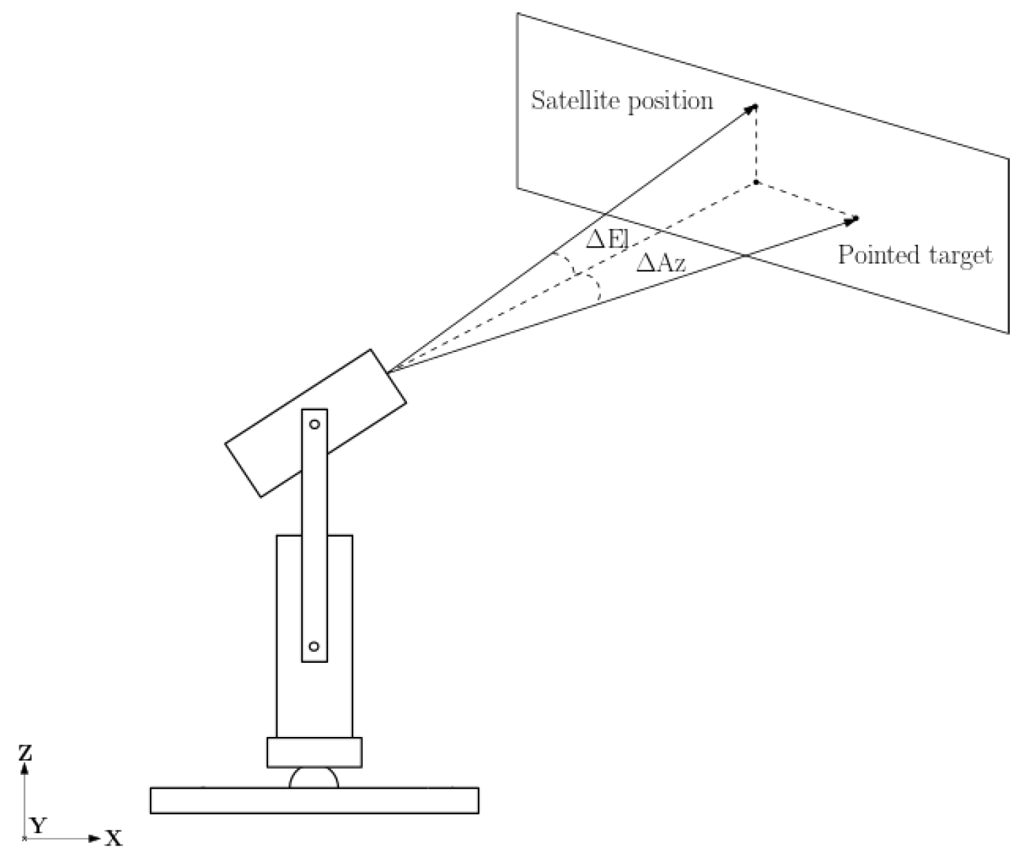
where ∆Az is the pointing error of the azimuth axis, and ∆El is the pointing error of the elevation axis. Az and El are the real azimuth and elevation values of the satellite, while
and
are the azimuth and elevation value respect to the pointed target (
Figure 11). The pointed target differs from the satellite position due to the presence of ship motions (and relative errors) and the errors in satellite coordinates.
Following a transitional phase during which the pointing system shifts from its initial position to the pointing one, the error is expected to converge towards zero if the satellite is precisely pointed.
Figure 12 depicts the accuracy error in pointing in terms of ∆Az and ∆El, i.e., the difference, in terms of azimuth and elevation, between the real position of the satellite and the position pointed by the system.
Figure 12a depicts the errors in both transition and pointing phases, while
Figure 12b provides a more focused representation of the error during the pointing phase. The system requires an error less than 100 µrad to enable quantum communication; in
Figure 12c, the red circle identifies the upper limit of the ∆Az and ∆El errors that can be admitted to achieve the satellite’s pointing.
If the system is able to always point the satellite, the error of the pointing phase is contained within this circle area (locking area,
Figure 12c).
In the example shown, it can be seen that the system achieves the required pointing accuracy only once in the 10 s time interval considered for the simulation. The result obtained may be different in other scenarios, and the satellite may never be pointed; therefore, it will be necessary to incorporate methodologies to achieve a higher level of pointing accuracy. It is also considered necessary to increase the pointing speed in terms of the time in which the system can point the satellite in order to reduce the information lag. Once the satellite has been pointed, the tracking phase can begin [
10], but it is still considered necessary for the system to be able to point the satellite with greater accuracy so that even in the case of target loss, the satellite can be re-targeted quickly.
2.8. Increasing of Pointing Accuracy
In order to increase the pointing accuracy in order to obtain a pointing error of less than 100 µrad, an additional motion may be added to the ATP system’s Body and Pointer to increase the possibility that the tracking phase takes place (
Figure 13).
The operation illustrated by the control diagram is the same as that described in
Section 2.5, with two additional blocks (
Figure 13 bottom left part) introducing an additional motion to the ATP system’s DoFs.
2.8.1. Conical Scanning
Conical scanning is obtained by adding a helicoidal shift to the Pointer.
Considering P = (Px,Py) as the designated point achieved during the pointing phase, the resulting Pointer motion with helicoidal scanning can be determined as follows [
29]:
in which r
s and ω are, respectively, the conical scanning amplitude and frequency.
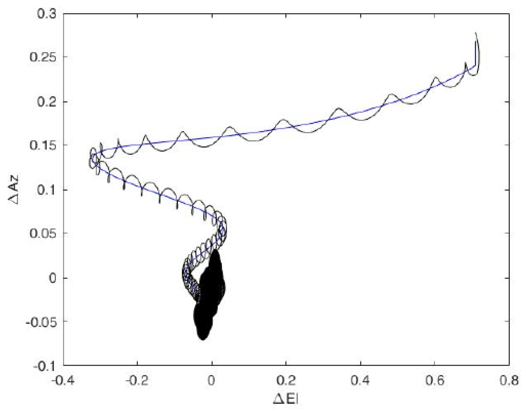
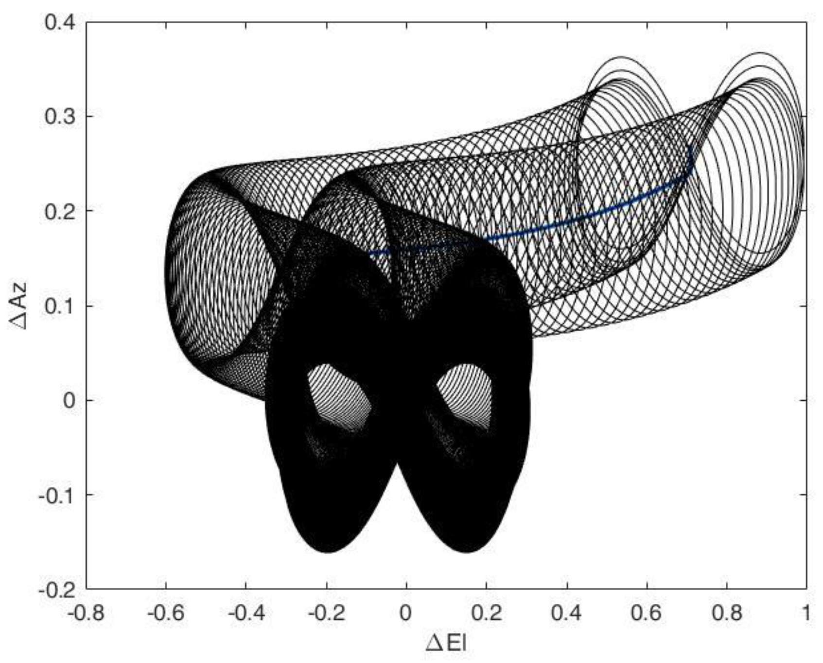
Figure 14 depicts the pointing accuracy graph in the case of helicoidal scanning.
The locking area evaluation led us to identify an increase in pointing accuracy (
Figure 15) with an increment of the number of times in which the system reached the requested pointing accuracy.
2.8.2. Bernoulli’s Lemniscate Scanning
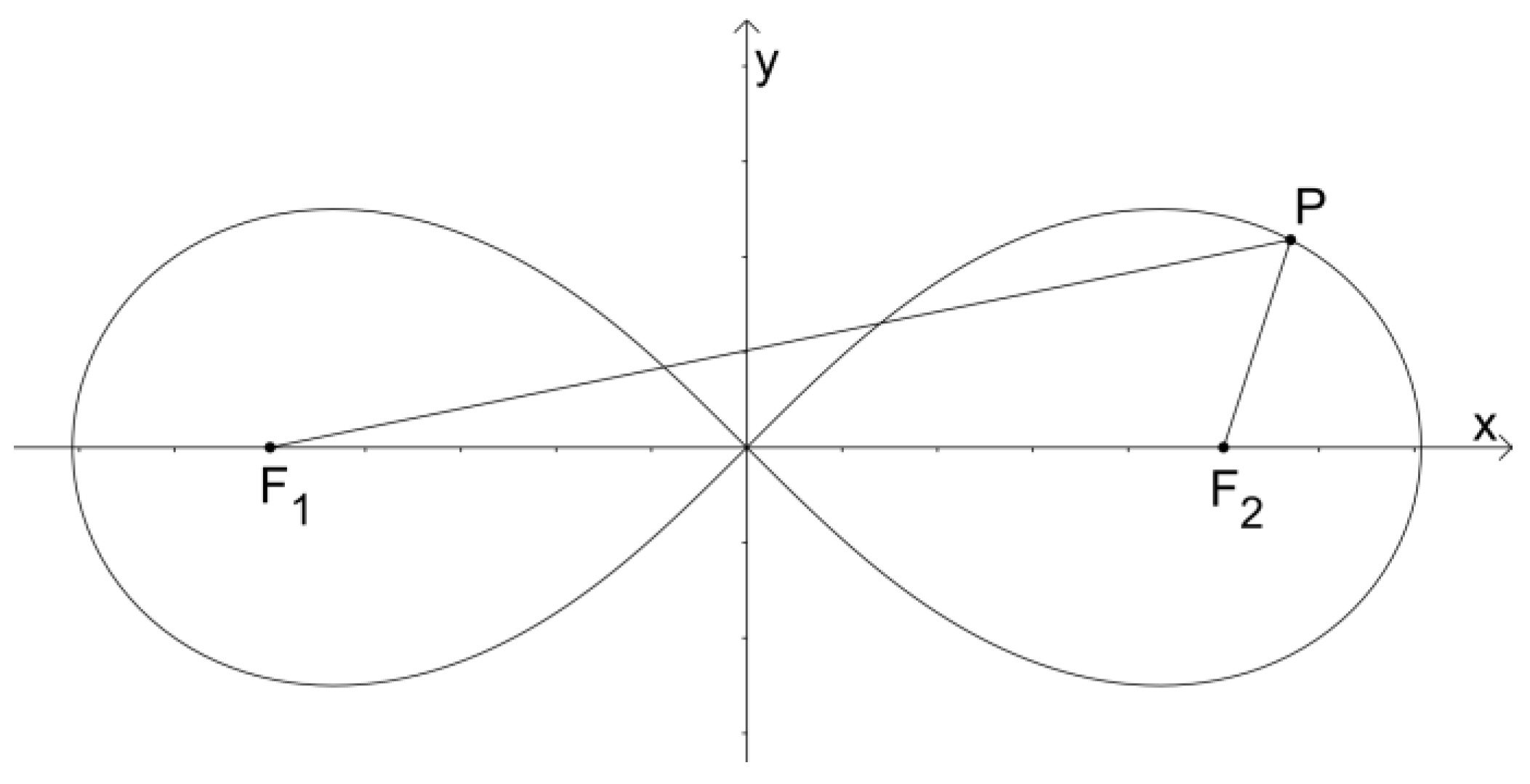
To evaluate the possibility of further increasing the pointing accuracy, another methodology of scanning can be analyzed. The lemniscate of Bernoulli is a plane curve defined from two given points, known as foci, at a distance 2c from each other as the locus of the point P, so that PF1∙PF2 = c
2 (
Figure 16).
Considering P = (Px,Py) as the designated point achieved during the pointing phase, and
a the half-width of the Bernoulli’s lemniscate (a = c∙
), it is possible to define the parametric equation of lemniscate scanning [
30] along the
X-axis (Equation (13)) and
Y-axis (Equation (14)).
Figure 17 depicts the pointing accuracy graph in the case of Bernoulli’s lemniscate scanning:
3. Results and Implementation of the Optical System to Improve Pointing Accuracy
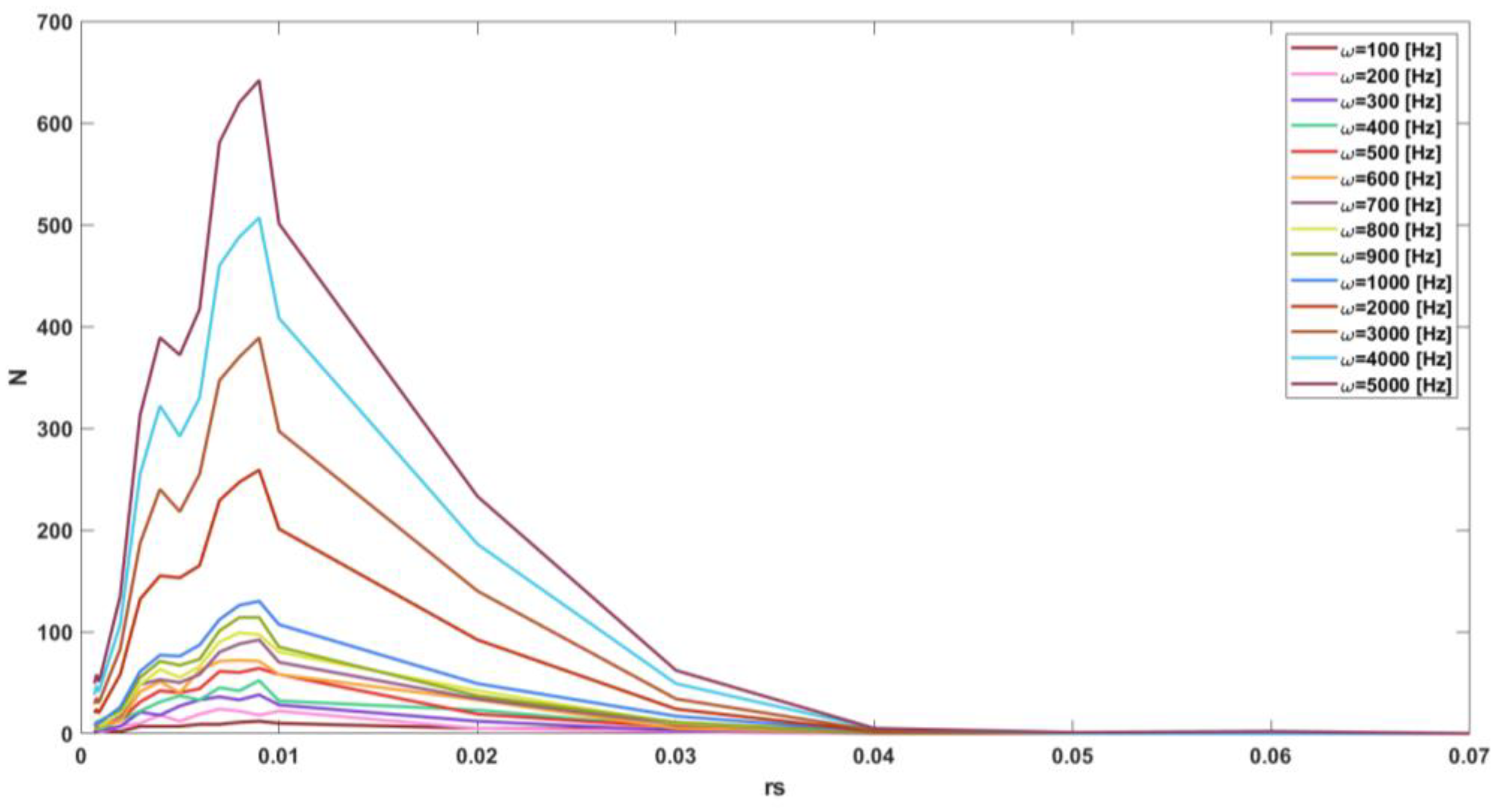
By changing the conical scanning amplitude r
s and frequency ω (Equations (11) and (12)), it was possible to evaluate the number of times (N) in which the system reached the requested pointing accuracy (
Figure 18).
In the case of conical scanning (
Figure 18), N = N
max when the r
s value is 0.009 and decreases up to N = 0 when the r
s > 0.04.
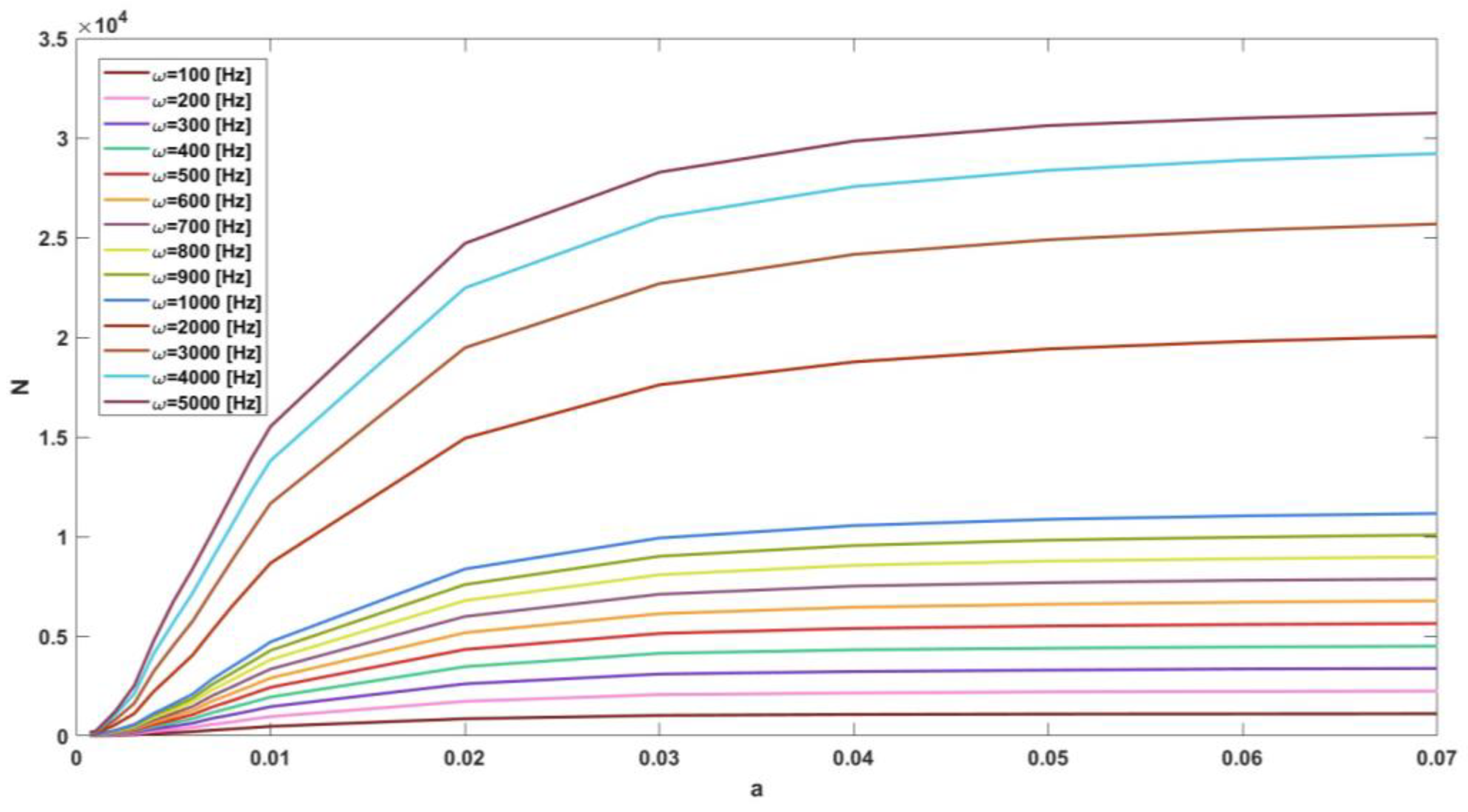
A similar approach has been used in the case of Bernoulli’s lemniscate scanning (
Figure 19), in which the times in which the system has reached the requested pointing accuracy have been evaluated by varying the half-width
a of the Lemniscate and the frequency ω (Equations (13) and (14)).
In the case of lemniscate scanning (
Figure 19), there is a slightly increasing trend of the function as
a changes with a number
N in the thousands, and N = N
max when
a is equal to 0.07.
The presented results in
Figure 18 and
Figure 19 are related to Scenario 01 of ship motions. (
Table 2). The results have been investigated for values of r
s and
a from 0.0007 to 0.07 and values of ω from 100 to 5000 Hz, as presented in
Figure 19 (or
Figure 18).
In both cases of adopted scanning strategies, N = Nmax when the scanning frequency ω is equal to 5000 Hz (higher values of ω were not considered for system feasibility).
In general, the analysis of the other three scenarios concerning ship motions did not show any substantial differences in the results (
Table 6), with N = N
max for ω equal to 5000 Hz, r
s = 0.009 for conical scanning and
a = 0.07 for lemniscate scanning.
In all scenarios, an increasing number of transitions was determined as the scanning frequency increased.
Considering that four different scenarios of several sea conditions were analyzed, and a similar trends were determined, it can be stated that the pointing, when a scanning strategy is adopted, is not so particularly influenced by navigation conditions as it is by errors in the acquisition of the satellite coordinates and the ship’s motions.
This substantial difference between conical and lemniscate scanning in terms of Nmax lies in the shape of the chosen scanning methodology, with lemniscate scanning being more effective in ensuring the transition from the pointing to the tracking phase of the system.
The improvement in pointing accuracy, considering Scenario 02 of ship motions (
Table 2) and scanning methodologies, analyzing the results for N = N
max, leads to the satellite’s first targeting time (deviation from the initial position to the targeting position) of 0.05 s for conical scanning and 0.013 s for lemniscate scanning.
The greater probability of targeting the satellite led to the adoption of lemniscate scanning methodology.
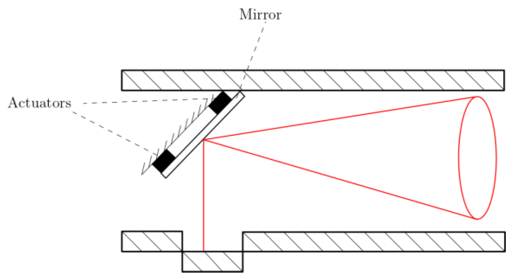
The shifting of the line of sight arising from the adopted scanning methodology in order to improve pointing accuracy can be carried out through the swaying of the mirror inside the optical system reflecting the laser beam (
Figure 20).
In order to ensure the feasibility of the system, a lemniscate scanning frequency ω of 3500 Hz and a value
a equal to 0.007 (Equations (13) and (14)) of the lemniscate half-width was chosen (the choice of ω and r
s parameters was made considering actuator specifications from the catalogue [
31] using an iterative method). The adopted scanning quantities ensured a first targeting time of 0.25 s alongside the probability of hitting the target once every 0.0013 s.
Figure 20 presents the optical system setup with four actuators linked to the optical mirror:
Considering a mirror radius (rm) equal to 0.015 m, thickness (s) equal to 0.01 m and mass (m) of about 0.016 kg, the actuators’ characteristics can be determined as follows.
The Equations (15) and (16) led to the selection of the actuator with a travel range of 108 µrad and a pull force of 125.7 N.
4. Conclusions
The conducted numerical analysis was focused on the assessment of the viability of satellite targeting through a pointing system, with the ultimate goal of realizing autonomously guided ships. The required pointing accuracy to start the communication phase and, thus, the transition from the pointing stage to the satellite-tracking phase should be higher to 100 µrad, and the system must ensure actual targeting even under different navigation conditions.
The analysis, considering a two-degrees-of-freedom acquisition, tracking and pointing (ATP) system located on the ship’s deck and, thus, subjected to the ship’s motions, revealed an increase in accuracy when methodologies for reducing pointing errors were employed. Through the numerical analysis, the four analyzed ship motion scenarios led to the final consideration that the pointing phase is influenced less by ship motions and more by errors in satellite position and ship motions acquisition in the case in which a scanning methodology of the celestial vault is adopted.
Between the two analyzed methodologies for improving pointing accuracy, the lemniscate scanning methodology proved to be more effective, showing a higher probability of achieving the required pointing accuracy.
The higher scanning frequencies led to the choice of implementing the scanning methodology by deviating the laser beam through the swaying of the optical system mirror.
The mirror swaying was realized through four actuators linked to the mirror, and the choice of actuators was evaluated through the actuators’ characteristics of travel range and pull force.
In order to ensure the feasibility of the system, a lemniscate scanning frequency ω of 3500 Hz and a value
a (half-width of the lemniscate) equal to 0.007 was chosen (the choice of ω and r
s parameters was made considering actuator specifications from the catalogue [
31] using an iterative method). In the assessment, it was taken into account that the pull force is proportional to the square of the frequency, while the travel range is proportional to the scanning amplitude. The outcomes led to the selection of actuators with a travel range of 108 µrad and a pull force of 125.7 N that ensure both a first satellite-targeting time of 0.25 s alongside the probability of hitting the target once every 0.0013 s (pointing accuracy greater than 100 µrad).
In this study, several sea conditions and the errors associated with the acquisition of ship motions and satellite coordinates were considered. Future developments concern the consideration of adverse weather conditions that may affect the pointing phase (e.g., fog or rain) and, thus, the system development to ensure communication in all sea and weather conditions. Additionally, geometric and installation errors should also be included in the numerical simulation to obtain a more realistic operation of the system.
