Technical Note

Fast Solution of Scattering and Micro-Doppler Features from Moving Target Using a Tailored Shooting and Bouncing Ray Method

School of Physics, Xidian University, Xi’an 710071, China
*
Author to whom correspondence should be addressed.
Remote Sens. 2023, 15(24), 5724; https://doi.org/10.3390/rs15245724
Submission received: 26 October 2023 / Revised: 1 December 2023 / Accepted: 11 December 2023 / Published: 14 December 2023

Abstract

:
In this paper, we present a tailored shooting and bouncing ray (SBR) method for the fast solution of electromagnetic (EM) scattering from a moving target. And, the micro-Doppler features of the moving target are investigated using a time-frequency analysis technique. In our method, a dynamic spatial division technique is employed to accelerate facet information processing and ray-tracing progress of the moving target. At first, the two coordinate systems are established, which are the geodetic coordinate system (GCS) and the local coordinate system (LCS). In GCS, the target is moving with translation and rotation. The dynamic spatial division is established in LCS to store the facet information and remain relatively stationary to the target. In comparison with the traditional SBR method, this technique avoids repetitive spatial division at each moment in the GCS. Then, ray tracing is performed to find the illuminated facets in the LCS. Finally, the scattering field and the phase compensation are computed in the GCS. In numerical simulations, the verification and computation efficiency comparison are provided using our method and other solutions (MLFMM, RL-GO, and traditional SBR). Moreover, the micro-Doppler features are extracted and analyzed using the time-frequency analysis technique, which includes the precession and spin of the missile, and the rotation of the aircraft. Meanwhile, the micro-Doppler spectra of the target is also compared with the theoretical Doppler of equivalent strong scattering points, which are obtained using the instantaneous high-resolution range profile (HRRP).

1. Introduction

Research on the electromagnetic (EM) scattering of a target is essential for radar detection and target recognition. With the development of computational electromagnetics, the methods for solving EM scattering problems have matured considerably over the past decades. For example, the method of moments (MOM) [1], the finite difference time domain (FDTD) [2], and the multilevel fast multipole method (MLFMM) [3] can achieve high-precision calculation; however, these methods are incapable for electrically large structures due to computing resources. Therefore, some high-frequency approximation methods are becoming increasingly popular in the field of EM calculation due to faster calculation speed and less resource consumption. Among them, physical optics (PO), geometric optics (GO), and ray-launching geometrical optics (RL-GO) [4] are more common, as well as the shooting and bouncing ray (SBR) method [5], which combines the two methods of PO and GO. In the SBR method, GO regulates the rules of wave propagation, and PO integrations are implemented to calculate the scattering field. Therefore, the SBR method is often applied to solve the EM scattering of electrically large complex structural targets [6]. In addition, the physical diffraction theory (PTD) combined with SBR can solve the problem of edge diffraction [7] to improve the calculation accuracy. A series of methods have been proposed to accelerate the ray-tracing process in SBR. The tree structure algorithm [8] and some of its improvements [9,10] were proposed to speed up the process of ray tracing. The time-domain SBR based on the beam tracing (BT) technique [11] was also proposed to improve the accuracy and computational efficiency. The Open Graphics Library (OpenGL) hybrid SBR method [12] was proposed to accelerate shadow removal. At the same time, some technical solutions [13] combined with SBR have been used to process complex scenes with remarkable effectiveness.
The methods mentioned above were focused on solving EM scattering of a stationary target. There are few works on researching the EM scattering and micro-Doppler features of a moving target based on high-frequency algorithms. The research of frequency characteristics based on EM scattering helps to provide theoretical support for radar detection and target identification [14,15], as well as SAR image processing [16,17]. Since the micro-Doppler features generated using different micro-motions are different, they also can be utilized to classify and recognize targets [18,19,20,21]. Chen has conducted a lot of excellent work on the micro-Doppler. He introduced the micro-Doppler phenomenon from microwave radar and established the micro-Doppler models caused by different motion forms [22]. With the deepening of research, the time-frequency analysis technology has become the main method to study micro-Doppler features [23]. Gao et al. [24] adopted this technology to analyze the micro-Doppler features of ballistic targets. The micro-Doppler features of rotor blades in different frequency bands were also investigated by [25,26]. This joint time-domain and frequency-domain analysis technology [27] can reveal the distribution of the Doppler spectra in the time domain.
However, all the works [20,21,22,23,24] above were based on the point scattering model of a moving target. This method just considers the scattering echo of a few strong scattering points on the target, ignoring the influence of structural features on the scattering echo. And the traditional EM scattering algorithms, such as MLFMM and MOM [26], consume too much computational resources in dealing with EM scattering from a moving target. In this paper, the micro-Doppler features of a moving target are investigated using EM modeling, and the dynamic spatial division technique-based SBR method is adopted to accelerate the solution of EM scattering with a moving target. At first, the geodetic coordinate system (GCS) and the local coordinate system (LCS) of the target at each moment are established. In LCS, the boundary of the target at the initial moment is determined and the spatial bounding box is constructed. The spatial bounding box stores facet information and remains relatively stationary to the moving target. In comparison with the traditional SBR method, this process avoids the spatial division at each moment. This will save lots of computational resources. Then, ray tracing is performed to find the illuminated facets in LCS. The illuminated facets information is converted from the LCS to the GCS by the rotation matrix-based coordinate system transformation. Finally, the scattering field and the phase compensation are computed in the GCS. The micro-Doppler features are extracted using the short-time Fourier transform (STFT), which is one of the time-frequency analysis techniques. In the simulation section, the effectiveness of the proposed method is verified by comparing the backscattering results of our method and other solutions (MLFMM, RL-GO, and traditional SBR), and the computation efficiency comparison is also given. Meanwhile, the micro-Doppler features of the moving target are analyzed, which includes the precession and spin of the missile, and the rotation of the aircraft. Moreover, the micro-Doppler spectra of the target is also compared with the theoretical Doppler of equivalent strong scattering points, which are obtained by the instantaneous high-resolution range profile (HRRP).
The remainder of this paper is organized as follows: In Section 2, the fast solution of the EM scattering model for a moving target is established, and the micro-Doppler features of the moving target are extracted using STFT. In Section 3, the accuracy and efficiency are verified by comparison with the results of our method and other solutions (MLFMM, RL-GO, and traditional SBR). The simulation results are discussed, including the micro-Doppler spectra of the missile and aircraft. The conclusion is reported in Section 4.

2. Fast Solution for EM Scattering and the Micro-Doppler of the Moving Target

2.1. Motion Modeling of the Target

Motion modeling is the foundation of solving the EM scattering of the moving target. Since the interaction time between the radar signal and targets is too short, target motion can be neglected. Therefore, the quasi-static method is utilized for motion modeling. Usually, the motion of the target can be divided into two parts: one is the translation relative to the radar irradiation direction, and the other is the rotation of the target relative to the radar coordinate system, as seen in Figure 1.
In a three-dimensional space, the position vector of point p in X Y Z L C S is r p L = [ r p _ x , r p _ y , r p _ z ] T . At moment t n , the position vector r p _ n G in x y z G C S is obtained by rotating r p L for an angle θ around the rotation axis ω = [ ω x , ω y , ω z ] T . It can be written as
r p _ n = R G L ( n ) × r p
where R G L ( n ) is the rotation matrix from X Y Z L C S to x y z G C S at moment t n , which can be expressed as
| G 0 L ( n ) = I 3 × 3 + ω ˜ sin θ + ω ˜ 2 ( 1 cos θ ) ω ˜ = [ 0 ω z ω y ω z 0 ω x ω y ω x 0 ]
where, I 3 × 3 is the unit matrix; ω ~ is a skew symmetric matrix of ω ; θ is the rotation angle of the target around the rotation axis ω at moment t n . Considering that the target also has a translation from X Y Z L C S to x y z G C S , then the motion of the target can be expressed in U V W G C S
r p _ n G = R 0 G G 0 + v t n L 0 L ( n ) + R G 0 L ( n ) × r p L
where R 0 G G 0 is the distance vector from x y z G C S to U V W G C S of the target at initial moment t 0 ; v t n is the translational vector from the position of moment t 0 to t n in X Y Z L C S . In this paper, the superscripts and subscripts of symbols such as ( ) G L represent the transformation relationship from the coordinate system LCS to GCS. L 0 and L ( n ) represent the LCS of the target at the initial moment and the nth moment, respectively.

2.2. Fast Solution for EM Scattering of the Moving Target Using the Tailored SBR Method

In the SBR method, GO regulates the rules of wave propagation, and then PO solves the induced EM current of the illuminated triangular facets. For example, the ray is reflected three times between the different facets of the trihedral shown in Figure 2. The initial facet illuminated by the incident ray is T 0 and the facet illuminated by the ray after the first-order reflection is T 1 ; then, the facet illuminated by the second-order reflection is T 2 . The total EM scattering field is contributed to by these illuminated facets, which include first-order and higher-order scattering. So, the SBR method greatly improves the calculation accuracy compared to the PO method.
In the traditional SBR method, the consumption of computational resources is mainly focused on two parts, creating spatial division to process facet information and ray tracing to find illuminated facets. In addition, the spatial division needs to be rebuilt for each moment in x y z G C S , which will consume large computational resources. In this paper, the rotation matrix-based coordinate system transformation is employed to establish the dynamic spatial division, and bidirectional ray-tracing technology [28] is adopted to accelerate the faceted information process and the ray-tracing process.
As shown in Figure 2b, in x y z G C S , the target is moving with translation and rotation. The dynamic spatial division is established in X Y Z L C S to store facet information and remain relatively stationary to the target, which avoids the spatial division at each moment in x y z G C S . The transformation relationship from the coordinate system X Y Z L C S to x y z G C S is given by Equation (3).
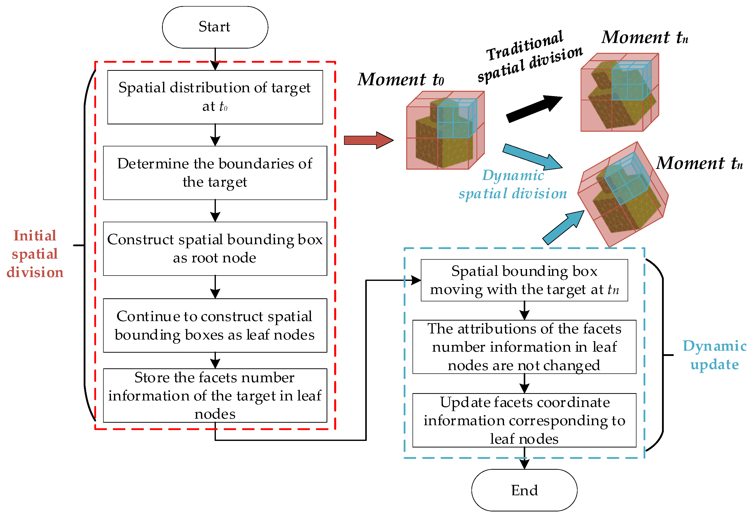
Figure 3 represents the flowchart for the dynamic spatial division. In this process, the spatial bounding box is moving with the target and remains relatively stationary. Thus, the facet number information stored in the leaf nodes does not change with the movement of the target. Only the coordinate information corresponding to the leaf nodes needs to be updated. Then, the new round of spatial division can be completed. Compared to traditional spatial division, there is no need to recognize the boundaries of the target and create a spatial bounding box at each moment. This will save lots of computational resources.
Figure 4 illustrates the geometry of the illuminated facet with rotation and translation. The facet T r i _ t n is illuminated by the incident electric field E i n c G in x y z G C S . The TE and TM waves can be expressed as
E i n c G = E i n c T E G L ( n ) ,   E i n c T M G L ( n ) T E i n c T E G L ( n ) = E i G e ^ T E G L ( n ) e ^ T E G L ( n ) E i n c T M G L ( n ) = E i G e ^ T M G L ( n ) e ^ T M G L ( n )
where e ^ T E G L ( n ) and e ^ T M G L ( n ) are direction vectors of TE and TM, respectively, which can be obtained by
e ^ T E G L ( n ) = k ^ i × N ^ G L ( n ) k ^ i × N ^ G L ( n ) e ^ T M G L ( n ) = e ^ T E G L ( n ) × k ^ i
where k ^ i is the direction vectors of the incident wave; N ^ G L ( n ) = R G L ( n ) × N ^ L ( n ) is the normal unit vector of T r i _ t n . The induced electric and magnetic current of illuminated facet T r i _ t n can be solved using the PO method
J G L ( n ) M G L ( n ) = ( 1 R T E G L ( n ) ) Γ 1 ( 1 + R T M G L ( n ) ) Γ 2 ( 1 + R T E G L ( n ) ) Γ 2 ( 1 R T M G L ( n ) ) Γ 1 E i n c T E G L ( n ) E i n c T M G L ( n )
Γ 1 = N ^ G L ( n ) k ^ i e ^ T E G L ( n ) Γ 2 = N ^ G L ( n ) × e ^ T E G L ( n )
where R T E / T M G L ( n ) is the reflection coefficient of the illuminated facet T r i _ t n , which can be obtained by
R T E / T M G L ( n ) = 1 P o t T E / T M N ^ G L ( n ) 1 + P o t T E / T M N ^ G L ( n )
P o t T E / T M N ^ G L ( n ) = μ r ε r 1 + ( N ^ G L ( n ) k ^ i ) 2 Ζ T E / T M ( N ^ G L ( n ) k ^ i )
in Equation (9), Ζ T E = μ r and Ζ T N = ε r , which are the relative permittivity and relative permeability of T r i _ t n .
The far-field scattering of T r i _ t n in x y z G C S can be approximated using the PO integral
E P O G ( R , t n ) = j k η exp ( j k R ) 4 π R s ^ × [ s ^ × J G L ( n ) + 1 η M G L ( n ) ] χ
χ = S exp [ j k ( i ^ s ^ ) r G L ( n ) ] d S
where η = ε 0 / μ 0 ; k = ω ε 0 μ 0 ; i ^ and s ^ are the unit vectors in the incident direction and the scattering direction, respectively; R is the distance from the source point to the observed point. Figure 5 represents the flowchart for solving the scattering field of T r i _ t n . The χ is the Gordon surface integral [29], and it can be written as
χ = S exp [ j k ( i ^ s ^ ) r | G L ( n ) ] d S     = { S exp [ j k α r c | G L ( n ) ] β = 0 j 1 k β | G L ( n ) m = 1 3 [ h ^ | G L ( n ) d m | G L ( n ) ] exp ( j k r m | G L ( n ) α ) sin c ( k d m | G L ( n ) α 2 ) β 0
where S represents the area of triangular facet T r i _ t n ; α = ( i ^ s ^ ) ; r c G L ( n ) is the center point vector of the facet T r i _ t n ; d m G L ( n ) and r m G L ( n ) are the vector along the mth edge and the midpoint coordinate of the facet T r i _ t n ; r c G L ( n ) , d m G L ( n ) , and r m G L ( n ) can be obtained by Equation (3). In Equation (12), h ^ G L ( n ) and β G L ( n ) can be obtained by
h ^ G L ( n ) = N ^ G L ( n ) × α / | N ^ | G L ( n ) × α β G L ( n ) = α α · N ^ G L ( n ) N ^ G L ( n )
considering that the facet also has translational motion, and the translational vector is T = v t n , as shown in Figure 3. Hence, the phase compensation φ T for translation is performed
φ T = exp [ j k α r T G L ( n ) r G L 0 ] = exp ( j k α T )
then, the total phase function of the illuminated triangular facet moving from T r i _ t 0 to T r i _ t n can be expressed as
φ n = φ T exp [ j k α r | G L ( n ) ]           = exp [ j k α ( T + | G L ( n ) × r L ( n ) ) ]
In the SBR method, high-order ray tracing is also a critical step. The irradiation area of the reflected ray usually covers multiple triangular facets, as shown in Figure 6. In this paper, the bidirectional ray-tracing technology is adopted to judge whether the facets are illuminated. The facet 0 is irradiated by the incident wave. The reflected ray starts from the center of facet 0 and reaches facet 13. Facet 13 is identified using forward ray tracing as one of the illuminated facets. The backward ray tracing is performed in the opposite direction of the reflected rays, which starts from the neighboring centers of facet 13 (facets 7, 12, and 14). If the backward ray intersects facet 0, then the neighboring facet is also one of the facets irradiated by the reflected wave. For a facet of the illuminated area, its adjacent facets will be checked by backward ray tracing. This bidirectional ray-tracing technique combined with neighboring findings improves the efficiency of ray tracing. For the illuminated facets, the far-field scattering can be approximated by Equation (10).

2.3. Time-Frequency Analysis for the Micro-Doppler

In Equations (10) and (15), the scattering field and phase function of the illuminated triangular facet moving with rotation and translation are derived. This can be simplified and written as
E n s = E n s s ^ φ n φ n = exp j α Φ n 2
where s ^ is the unit vector in the scattering direction; E n s represents the amplitudes of the scattering field. The change process of phase Φ n and micro-Doppler frequency shift induced by the motion of this facet to the incident direction can be obtained by
Φ n = 2 k ( T + R G L ( n ) × r G L 0 )
f n m D ( t ) = 1 2 π d Φ n d t                             = 2 f c [ v + d ( | G L ( n ) × r | G L 0 ) d t ]
where f is the incident frequency; v is the velocity vector of translation; R G L ( n ) × r G L 0 is the coordinate system transformation from the LCS to the GCS induced by rotation; and the amplitude of the scattered field corresponding to this Doppler frequency f n m D is E n s .
In order to solve the overall micro-Doppler shift of the target with motion, it is often necessary to resort to the STFT, which is one of the time-frequency analysis techniques. The steps of the STFT are performed as follows.
  • Step 1: The window function w ( t ) is moved to the starting position of the time sequence E s 0 n . At this time, the center position of w ( t ) is at t = τ 0 , and the scattering field sequence is processed by the window function
    s 0 ( t ) = E s 0 n w ( t τ 0 )
  • Step 2: The fast Fourier transform (FFT) is performed on a small sequence covered by the window function to obtain the Doppler shift of this sequence and it can be expressed as
    S f m D ,   τ 0 = F [ s 0 ( t ) ] = F [ E s 0 n w ( t τ 0 ) ]
    where F [ ] represents the FFT operation;
  • Step 3: After completing the FFT of the first sequence, the center of the window function is moved to t = τ 1 . The moving distance should be less than the width of the window function, to ensure that there is an overlap between the two windows;
  • Step 4: Repeat the above operation as shown in Figure 7, continuously slide the window function and process the sequence using FTT, and finally get the Doppler frequency spectra of all segments on τ 0 ~ τ m .
Thus, the micro-Doppler features of a moving target based on EM scattering are extracted using the time-frequency analysis technique. This can be expressed as
S f m D ,   τ i = F [ s i ( t ) ] = F [ E s 0 n w ( t τ i ) ]
where i = 0 ~ m , S f m D ,   τ i is the micro-Doppler distribution at moment τ i .
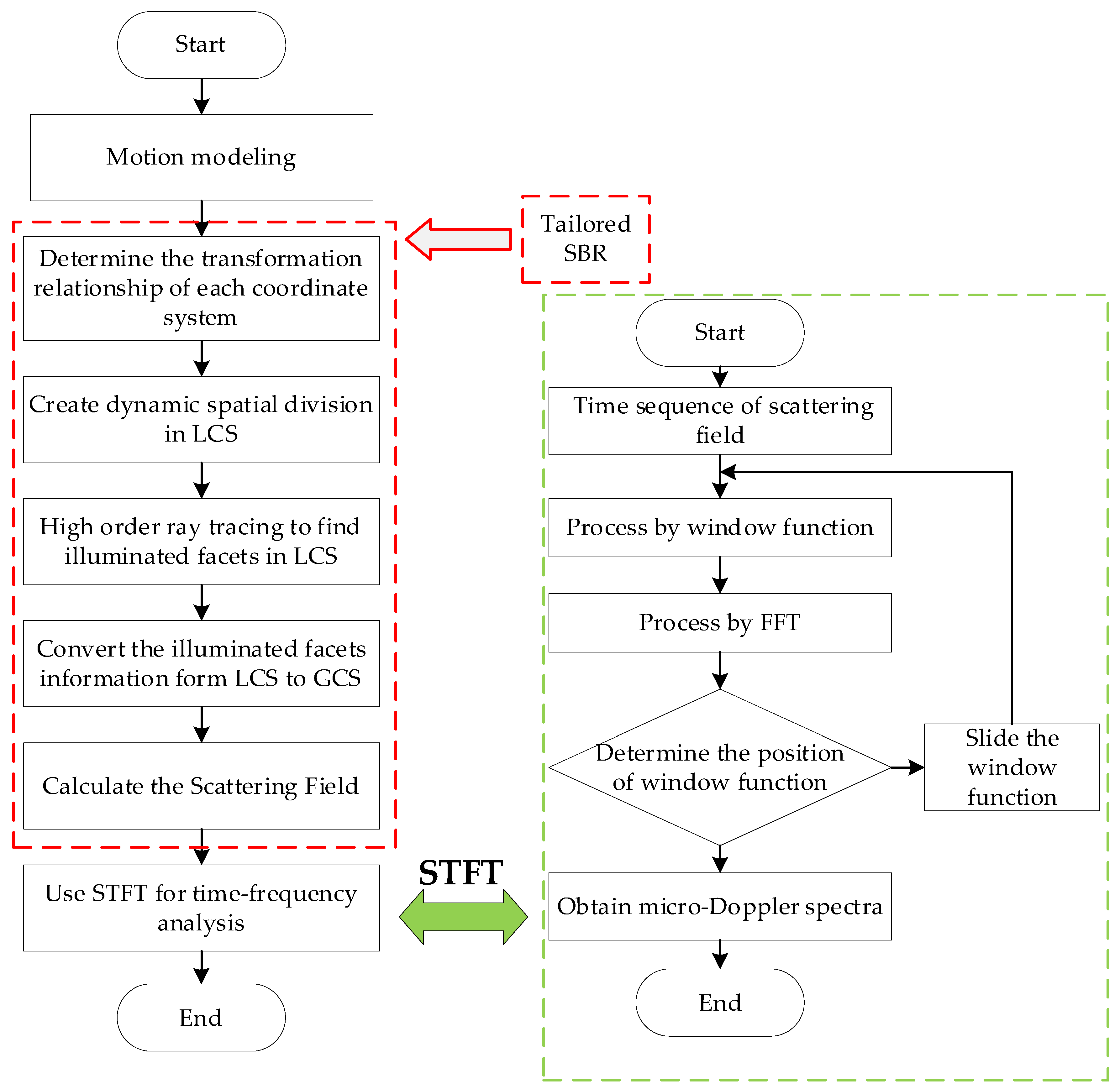
For better understanding, Figure 8 represents the flowchart for the method proposed in this paper to accelerate the solution of EM scattering and the micro-Doppler time-frequency spectra with a moving target.

3. Simulation Results and Discussion

In this section, first, the EM scattering of the moving target is simulated using our method and compared with the results of MLFMM, RL-GO, and the traditional SBR method [28]. Meanwhile, the computation efficiency comparison is given. Then, the micro-Doppler features of the moving target are analyzed, which include the precession and spin of the missile and the rotation of the aircraft. Moreover, the micro-Doppler spectra of the target is also compared with the theoretical Doppler of the equivalent strong scattering points, which are obtained using the instantaneous HRRP. The geometric model adopted in this paper is shown in Figure 9. All simulations were performed on a computer with Intel(R) Xeon(R) Platinum 8275CL at 3.6 GHz and 384 GB RAM.

3.1. EM Scattering of the Moving Target

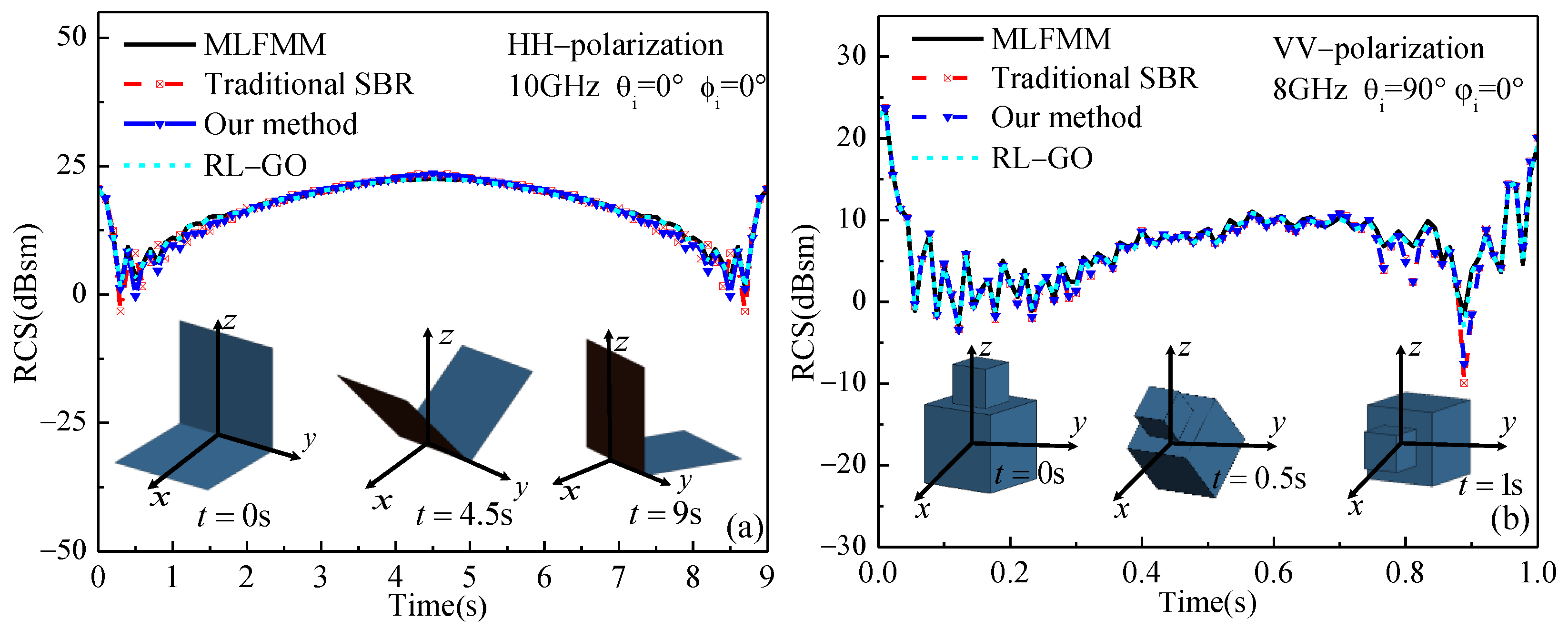
In Figure 10, the backscattering of the dihedral angle and combined model are compared with our method and other solutions (MLFMM, RL-GO, and the traditional SBR). Figure 10a is the scattering of the dihedral angle composed of two 0.5   m × 0.5   m plates with HH polarization. The dihedral angle rotates around the y-axis with an angular velocity of ω = π / 18   rad / s . Where the incident frequency is f = 10   GHz , the incident angle is θ i = 0 ° , and the azimuth angle is ϕ i = 0 ° . Figure 10b is the scattering of the combined model composed of two cubes with side lengths of 0.4   m and 0.2   m , respectively. The combined model rotating around the y-axis with an angular velocity is ω = π / 2   rad / s . Where the incident frequency is f = 8   GHz , the incident angle is θ i = 90 ° , the azimuth angle is ϕ i = 0 ° , and the polarization is VV. In this section, since there is need to evaluate the effectiveness of our method, some statistical concepts are utilized to measure the deviation degree of our method from other solutions. The mean absolute error μ and its standard deviation σ [7] are defined as
μ = 1 N i = 1 N x i , σ = 1 N 1 i = 1 N ( x i μ ) 2
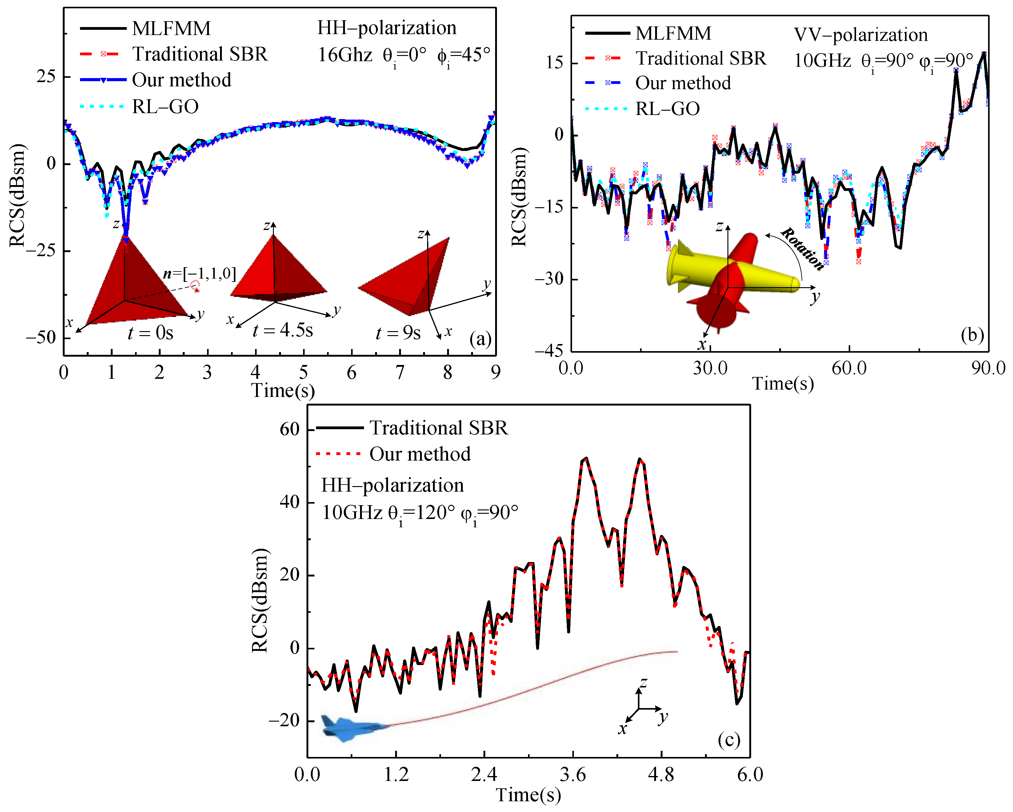
where x i are the differences between the predicted RCS values of our method and other solutions; and N is the total number of moments for target movement. Take the MLFMM and RL-GO results as the reference values, the μ and σ for our method are presented in Table 1. It is obvious that the μ and σ of our method are about 0.36~0.88 and 1.67~2.81. It indicates that these results using different methods match very well.
In Figure 11a,b, the backscattering of the trihedral corner reflector and missile is compared using our method and other solutions (MLFMM, RL-GO, and the traditional SBR). Figure 11c is the backscattering of aircraft compared using our method and the traditional SBR. Figure 11a is the scattering of the trihedral corner reflector composed of three right-angled triangles (right-angle side 0.3 m) with HH polarization. The trihedral corner reflector rotates around the rotation axis n = [ 1,1 , 0 ] with an angular velocity ω = π / 18   rad / s . Where the incident frequency is f = 16   GHz , the incident angle is θ i = 0 ° , and the azimuth angle is ϕ i = 45 ° . Figure 11b is the scattering of the missile with VV polarization. The missile rotates around the z-axis with an angular velocity ω = π / 180   rad / s . Where the incident frequency is f = 10     GHz , the incident angle is θ i = 90 ° , and the azimuth angle is ϕ i = 90 ° . Figure 11c is the scattering of the aircraft with HH polarization. The aircraft is performing a climbing motion at a speed of v = 120   m / s . Where the incident frequency is f = 10   GHz , the incident angle is θ i = 120 ° , and the azimuth angle is ϕ i = 90 ° . In Table 1, it is evident that our method shows good consistency with the MLFMM and RL-GO. In Table 2, the computation cost of Figure 10 and Figure 11 is compared between our method and other solutions. It can be seen from Table 2 that the method adopted in this paper has significant improvement in computational speed compared with the traditional SBR and MLFMM or RL-GO. And with the number of facets increasing, the acceleration effect is more obvious. The speedup of our method relative to traditional SBR is also given in Table 2.

3.2. Micro-Doppler of the Wingless Missile

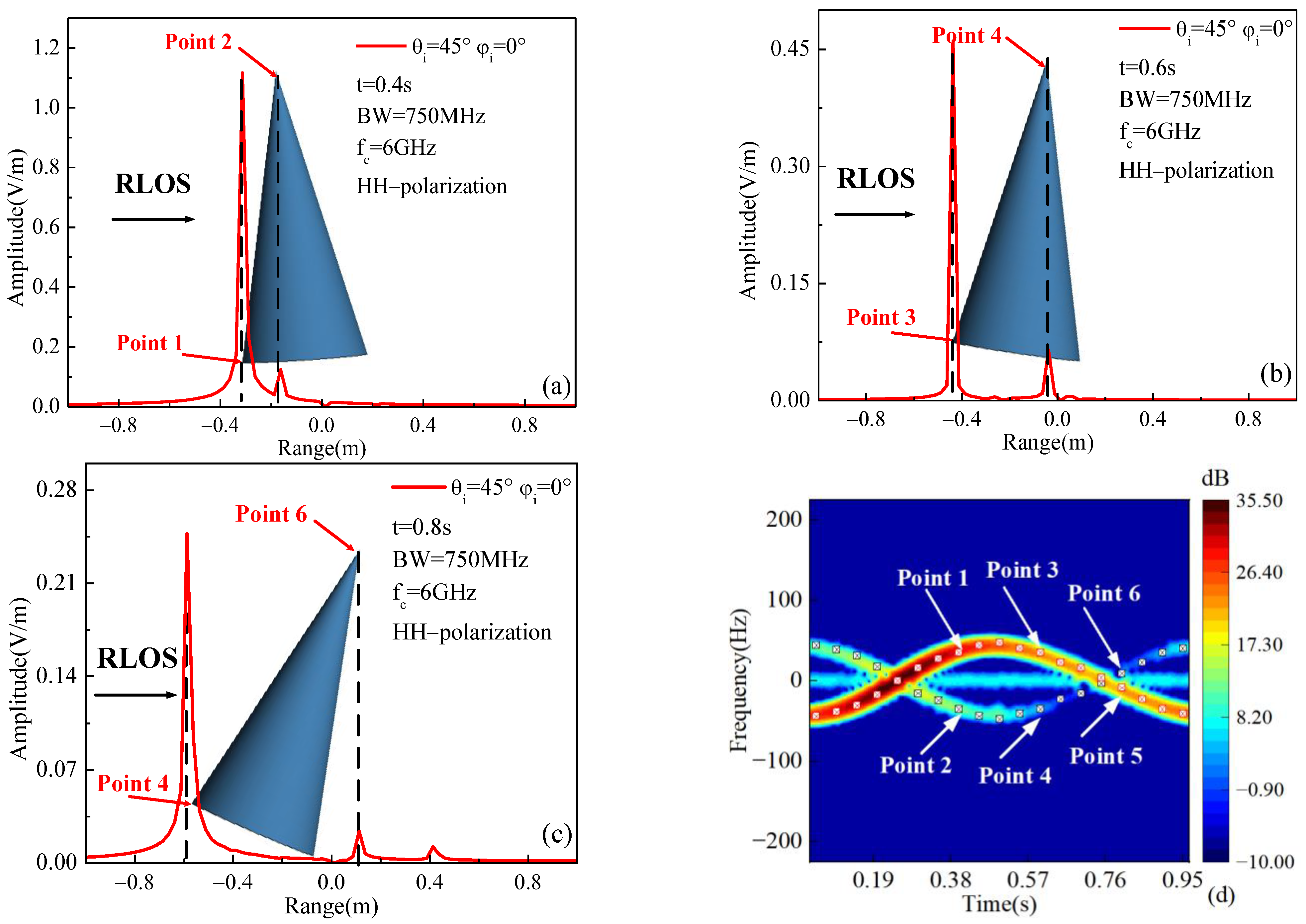
In Figure 12, the instantaneous HRRP and micro-Doppler of the wingless missile with precession are simulated using our method. The missile rotates counterclockwise with the angular velocity ω = 2 π   rad / s around the rotation axis n ^ = [ 0.1961,0.9806,0 ] . Where the incident frequency is f = 6   GHz , the incident angle is θ i = 45 ° , the azimuth angle is ϕ i = 0 ° , and the polarization is HH. In order to verify the micro-Doppler spectra in Figure 12d, the equivalent strong scattering point of the target can be extracted by calculating the instantaneous HRRP. It is the main component that causes the micro-Doppler at the time. The theoretical Doppler formula is given by Equation (19).
Figure 12a–c is the instantaneous HRRPs of the missile with precession at t = 0.4   s , 0.6 s , and 0.8 s . In Figure 12a–c, the equivalent strong scattering points are concentrated with the head (Point 2, 4, 6) and tail (Point 1, 3, 5) of the missile, and the intensity of the Point 2 (Point 4, 6) is weaker than Point 1 (Point 3, 5). Figure 12d is the verification of the theoretical Doppler and micro-Doppler spectra. In Figure 12d, the red scattering points are the theoretical Doppler calculated by points at the head, and the black scattering points are the theoretical Doppler calculated by points at the tail. It can be seen from Figure 12d that the micro-Doppler spectra is consistent with the theoretical Doppler of the equivalent scattering point for most moments.

3.3. Micro-Doppler of the Winged Missile

In this example, the instantaneous HRRP and micro-Doppler of the wingless missile with spin motion are presented in Figure 11. The missile rotates counterclockwise with the angular velocity ω = 2 π   rad / s around the y-axis to simulate spin motion. Figure 11a is the instantaneous HRRP of the missile with spin motion at t = 0.25   s  Figure 11b is the micro-Doppler spectra of the missile with spin motion. Where the incident frequency is f = 10   GHz , the incident angle is θ i = 90 ° , the azimuth angle is ϕ i = 0 ° , and the polarization is VV.
As shown in Figure 13a,b, the micro-Doppler spectra of the spin missile has two identical cycles and each cycle lasts 0.25   s . This is because the missile has four symmetrical tails. Thus, one cycle is generated every 0.25   s when the spin angular velocity is 2 π   rad / s . It can be also seen that the micro-Doppler frequency shift and the overall scattering intensity reaches the highest at t = 0.25   s . This is because at this moment the surface of the tail is vertical to the direction of the incident wave, as shown in Figure 13a. The theoretical Doppler of equivalent strong scattering points 1, 2, and 3 in Figure 13a are calculated, and compared with the micro-Doppler spectra shown in Figure 13b.
In Figure 14a, the missile rotates around n ^ = [ 0.1961,0.9806,0 ] to simulate cone motion and the rotational angular velocity of cone motion is ω = 2 π   rad / s . The precession in Figure 14b is a superposition of the spin motion in Figure 13 and the cone motion in Figure 14a.
In Figure 14b, the micro-Doppler of the precession motion can be clearly distinguished into two parts: the missile body (feature 1) and the tail (feature 2). The time interval between every feature 2 is 0.125   s . This is because when the missile spins, the micro-motion of the tail will produce four features 2. At the same time, the cone motion of the missile also causes four features 2 produced by the tail. Thus, there are eight features 2 in one progression cycle. Since the main part of the missile is also involved in a coning motion, the scattering intensity of eight features 2 is weaker than feature 1. In addition, due to the influence of the motion of the missile body, the eight features 2 in the micro-Doppler spectra are not symmetrical.

3.4. Micro-Doppler of the Aircraft

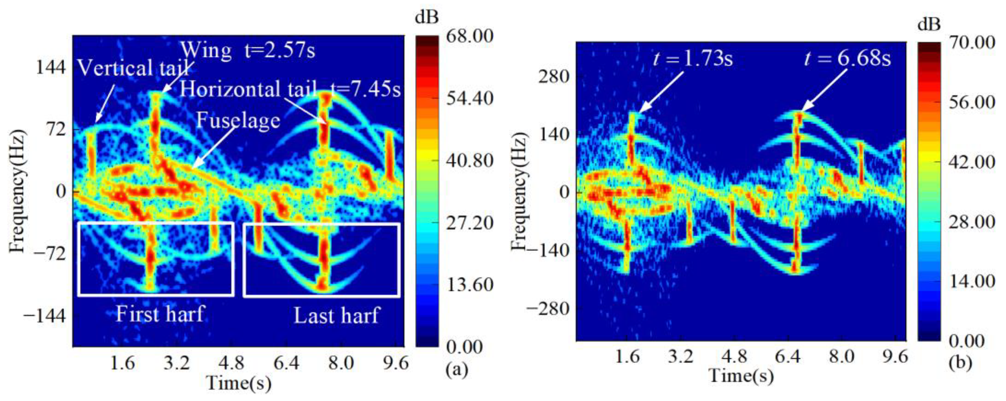
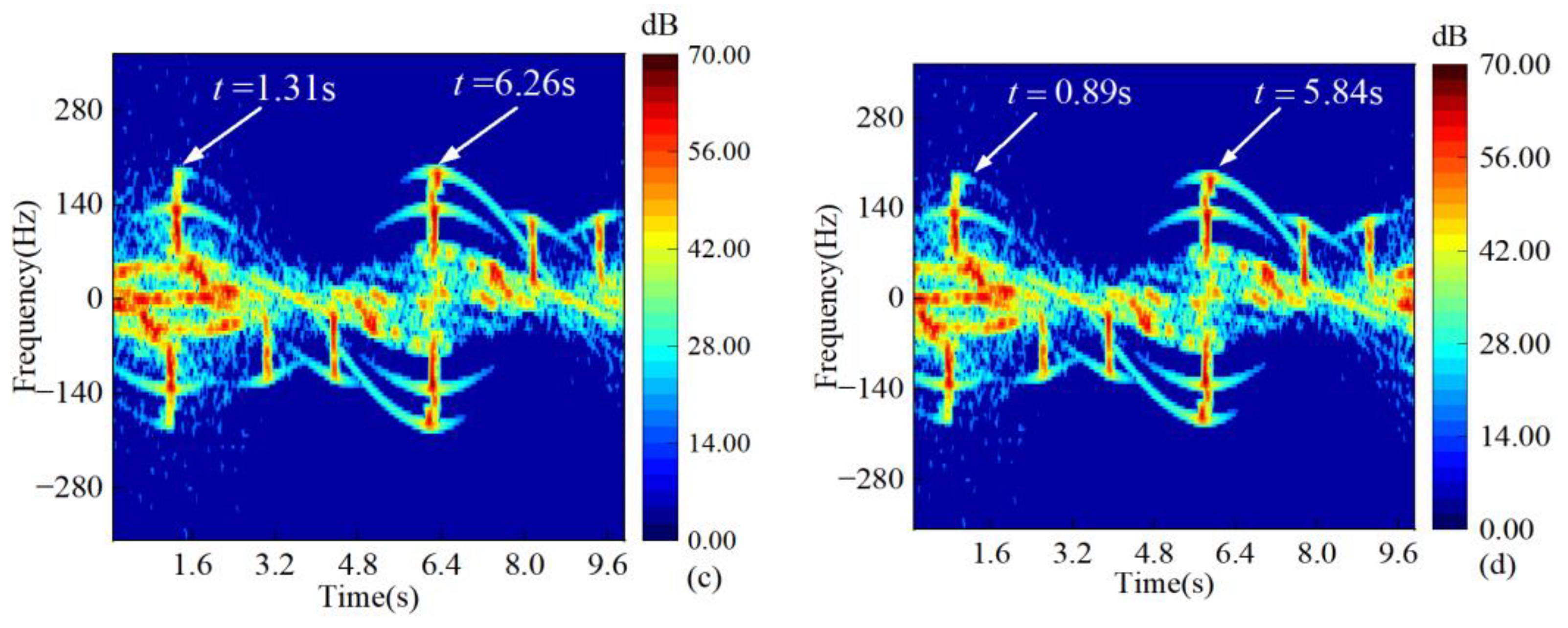
Figure 15 is the micro-Doppler spectra of the missile with a flipping motion in different incident angles. The aircraft rotates with the angular velocity ω = 0.2 π   rad / s around the y-axis to simulate a flipping motion. Where the incident frequency is f = 6   GHz , the incident angle is θ i = 90 ° , 60 ° , 45 ° , and 30 ° ; the azimuth angle is ϕ i = 0 ° ; and the polarization is HH. With the decrease in the incident angle, the variation in time-frequency ridges is reflected that the maximum of the Doppler shift is shifted to the left. The maximum of the Doppler shift is shifted to the left by 0.77 ~ 0.84   s when the incident angle θ i decreases by 30°. In addition, as shown in Figure 15a, time-frequency ridges in the first half of the cycle contain more micro-Doppler components than the last half. This is because the Doppler shift is contributed to by the micro-motion of the two vertical tails and other physical structures on the front of the fuselage; in addition, the front of the fuselage is more complex than the back, so the amount of Doppler shift information embodied in time-frequency ridges is more.

4. Conclusions

In this paper, the EM scattering of a moving target is solved using a tailored SBR method based on the dynamic spatial division technique. In this technique, the dynamic spatial division is established in the LCS to store the facet information and remain relatively stationary with the target. In comparison with the traditional SBR method, this technique avoids repetitive spatial division at each moment in the GCS, which greatly decreases the consumption of computing resources. In our numerical simulations, the verification and computation efficiency comparison are given by our method and other solutions (MLFMM, RL-GO, and traditional SBR method). Moreover, the micro-Doppler features are extracted and analyzed using the time-frequency analysis technique, which includes the precession and spin of the missile, and the rotation of the aircraft. Meanwhile, the micro-Doppler spectra of the target is also compared with the theoretical Doppler of the equivalent strong scattering points, which are obtained using the instantaneous HRRP. In our future work, the tailored SBR method in this paper will be improved to solve and analyze the scattering and micro-Doppler of multiple moving targets.

Author Contributions

Conceptualization, J.L. and Y.X.; methodology, Y.X. and W.M.; validation, Y.X. and S.W.; investigation, Y.X. and W.M.; writing—original draft preparation, Y.X.; writing—review and editing, J.L.; funding acquisition, J.L. and L.G. All authors have read and agreed to the published version of the manuscript.

Funding

This research was funded by the National Natural Science Foundation of China, grant numbers 61971338, 62231021, 62201435, U21A20457, and U20B2059; the Foundation for Innovative Research Groups of the National Natural Science Foundation of China, grant number 61621005; the Aeronautical Science Foundation of China, grant number 20172081009; the Fundamental Research Funds for the Central Universities, grant number ZYTS23068 and QTZX23010; and the Natural Science Basic Research Program of Shaanxi, grant number 2023-JC-YB-537.

Data Availability Statement

Not applicable.

Acknowledgments

The authors thank the editors and reviewers for their constructive suggestions.

Conflicts of Interest

The authors declare no conflict of interest.

References

  1. Rao, S.; Wilton, D.; Glisson, A. Electromagnetic scattering by surfaces of arbitrary shape. IEEE Trans. Antennas Propag. 1982, 30, 409–418. [Google Scholar] [CrossRef]
  2. Kuang, L.; Jin, Y.Q. Bistatic Scattering from a Three-Dimensional Object Over a Randomly Rough Surface Using the FDTD Algorithm. IEEE Trans. Antennas Propag. 2007, 55, 2302–2312. [Google Scholar] [CrossRef]
  3. Kong, W.B.; Zhou, H.X.; Zheng, K.L.; Hong, W. Analysis of Multiscale Problems Using the MLFMA With the Assistance of the FFT-Based Method. IEEE Trans. Antennas Propag. 2015, 63, 4184–4188. [Google Scholar] [CrossRef]
  4. Aguilar, A.G.; Jakobus, U.; Longtin, M.; Schoeman, M.; Strydom, W.; Tonder, J.J.V. Summary of the latest extensions to the electromagnetic field solver package FEKO. In Proceedings of the 2017 International Applied Computational Electromagnetics Society Symposium—Italy (ACES), Florence, Italy, 26–30 March 2017; pp. 1–2. [Google Scholar]
  5. Ling, H.; Chou, R.C.; Lee, S.W. Shooting and bouncing rays: Calculating the RCS of an arbitrarily shaped cavity. IEEE Trans. Antennas Propag. 1989, 37, 194–205. [Google Scholar] [CrossRef]
  6. Li, J.; Zhao, L.; Guo, L.-X.; Li, K.; Chai, S.-R. Hybrid PO-SBR-PTD method for composite scattering of a vehicle target on the ground. Appl. Opt. 2021, 60, 179–185. [Google Scholar] [CrossRef]
  7. Huang, W.F.; Zhao, Z.; Zhao, R.; Wang, J.Y.; Nie, Z.; Liu, Q.H. GO/PO and PTD With Virtual Divergence Factor for Fast Analysis of Scattering from Concave Complex Targets. IEEE Trans. Antennas Propag. 2015, 63, 2170–2179. [Google Scholar] [CrossRef]
  8. Bang, J.K.; Kim, B.C.; Suk, S.H.; Jin, K.S.; Kim, H.T. Time Consumption Reduction of Ray Tracing for Rcs Prediction using Efficient Grid Division and Space Division Algorithms. J. Electromagn. Waves Appl. 2007, 21, 829–840. [Google Scholar] [CrossRef]
  9. Feng, T.T.; Guo, L.X. An Improved Ray-Tracing Algorithm for SBR-Based EM Scattering Computation of Electrically Large Targets. IEEE Antennas Wirel. Propag. Lett. 2021, 20, 818–822. [Google Scholar] [CrossRef]
  10. Wang, H.; Wei, B.; Liu, H. A Fast Method for SBR-Based Multiaspect Radar Cross Section Simulation of Electrically Large Targets. IEEE Antennas Wirel. Propag. Lett. 2022, 21, 1920–1924. [Google Scholar] [CrossRef]
  11. Zhou, X.; Zhu, J.Y.; Yu, W.M.; Cui, T.J. Time-Domain Shooting and Bouncing Rays Method Based on Beam Tracing Technique. IEEE Trans. Antennas Propag. 2015, 63, 4037–4048. [Google Scholar] [CrossRef]
  12. Dong, C.-L.; Guo, L.-X.; Meng, X.; Wang, Y. An Accelerated SBR for EM Scattering from the Electrically Large Complex Objects. IEEE Antennas Wirel. Propag. Lett. 2018, 17, 2294–2298. [Google Scholar] [CrossRef]
  13. Zou, G.; Tong, C.; Zhu, J.; Sun, H.; Peng, P. Study on Composite Electromagnetic Scattering Characteristics of Low-Altitude Target Above Valley Composite Rough Surface Using Hybrid SBR-EEC Method. IEEE Access 2020, 8, 72298–72307. [Google Scholar] [CrossRef]
  14. Lan, L.; Marino, A.; Aubry, A.; Maio, A.D.; Liao, G.; Xu, J.; Zhang, Y. GLRT-Based Adaptive Target Detection in FDA-MIMO Radar. IEEE Trans. Aerosp. Electron. Syst. 2021, 57, 597–613. [Google Scholar] [CrossRef]
  15. Lan, L.; Xu, J.; Liao, G.; Zhang, Y.; Fioranelli, F.; So, H.C. Suppression of Mainbeam Deceptive Jammer With FDA-MIMO Radar. IEEE Trans. Veh. Technol. 2020, 69, 11584–11598. [Google Scholar] [CrossRef]
  16. Kang, M.S.; Baek, J.M. Efficient SAR Imaging Integrated with Autofocus via Compressive Sensing. IEEE Geosci. Remote Sens. Lett. 2022, 19, 1–5. [Google Scholar] [CrossRef]
  17. Kang, M.S.; Baek, J.M. SAR Image Reconstruction via Incremental Imaging with Compressive Sensing. IEEE Trans. Aerosp. Electron. Syst. 2023, 59, 4450–4463. [Google Scholar] [CrossRef]
  18. Shi, F.; Li, Z.; Zhang, M.; Li, J. Analysis and Simulation of the Micro-Doppler Signature of a Ship with a Rotating Shipborne Radar at Different Observation Angles. IEEE Geosci. Remote Sens. Lett. 2022, 19, 1–5. [Google Scholar] [CrossRef]
  19. Amiri, R.; Shahzadi, A. Micro-Doppler based target classification in ground surveillance radar systems. Digit. Signal Process. 2020, 101, 102702. [Google Scholar] [CrossRef]
  20. Wang, Z.; Luo, Y.; Li, K.; Yuan, H.; Zhang, Q. Micro-Doppler Parameters Extraction of Precession Cone-Shaped Targets Based on Rotating Antenna. Remote Sens. 2022, 14, 2549. [Google Scholar] [CrossRef]
  21. Chen, X.; Guan, J.; Huang, Y.; Liu, N.; He, Y. Radon-Linear Canonical Ambiguity Function-Based Detection and Estimation Method for Marine Target with Micromotion. IEEE Trans. Geosci. Remote Sens. 2015, 53, 2225–2240. [Google Scholar] [CrossRef]
  22. Chen, V.C.; Li, F.; Ho, S.S.; Wechsler, H. Micro-Doppler effect in radar: Phenomenon, model, and simulation study. IEEE Trans. Aerosp. Electron. Syst. 2006, 42, 2–21. [Google Scholar] [CrossRef]
  23. Chen, V.C. Joint time-frequency analysis for radar signal and imaging. In Proceedings of the 2007 IEEE International Geoscience and Remote Sensing Symposium, Barcelona, Spain, 23–28 July 2007; pp. 5166–5169. [Google Scholar]
  24. Gao, H.; Xie, L.; Wen, S.; Kuang, Y. Micro-Doppler Signature Extraction from Ballistic Target with Micro-Motions. IEEE Trans. Aerosp. Electron. Syst. 2010, 46, 1969–1982. [Google Scholar] [CrossRef]
  25. Gong, J.; Yan, J.; Li, D.; Chen, R.; Tian, F.; Yan, Z. Theoretical and Experimental Analysis of Radar Micro-Doppler Signature Modulated by Rotating Blades of Drones. IEEE Antennas Wirel. Propag. Lett. 2020, 19, 1659–1663. [Google Scholar] [CrossRef]
  26. Li, T.; Wen, B.; Tian, Y.; Li, Z.; Wang, S. Numerical Simulation and Experimental Analysis of Small Drone Rotor Blade Polarimetry Based on RCS and Micro-Doppler Signature. IEEE Antennas Wirel. Propag. Lett. 2019, 18, 187–191. [Google Scholar] [CrossRef]
  27. Chen, V.C. Spatial and temporal independent component analysis of micro-doppler features. In Proceedings of the IEEE International Radar Conference, Arlington, VA, USA, 9–12 May 2005; pp. 348–353. [Google Scholar]
  28. Fan, T.-Q.; Guo, L.-X.; Lv, B.; Liu, W. An Improved Backward SBR-PO/PTD Hybrid Method for the Backward Scattering Prediction of an Electrically Large Target. IEEE Antennas Wirel. Propag. Lett. 2016, 15, 512–515. [Google Scholar] [CrossRef]
  29. Gordon, W. Far-field approximations to the Kirchoff-Helmholtz representations of scattered fields. IEEE Trans. Antennas Propag. 1975, 23, 590–592. [Google Scholar] [CrossRef]
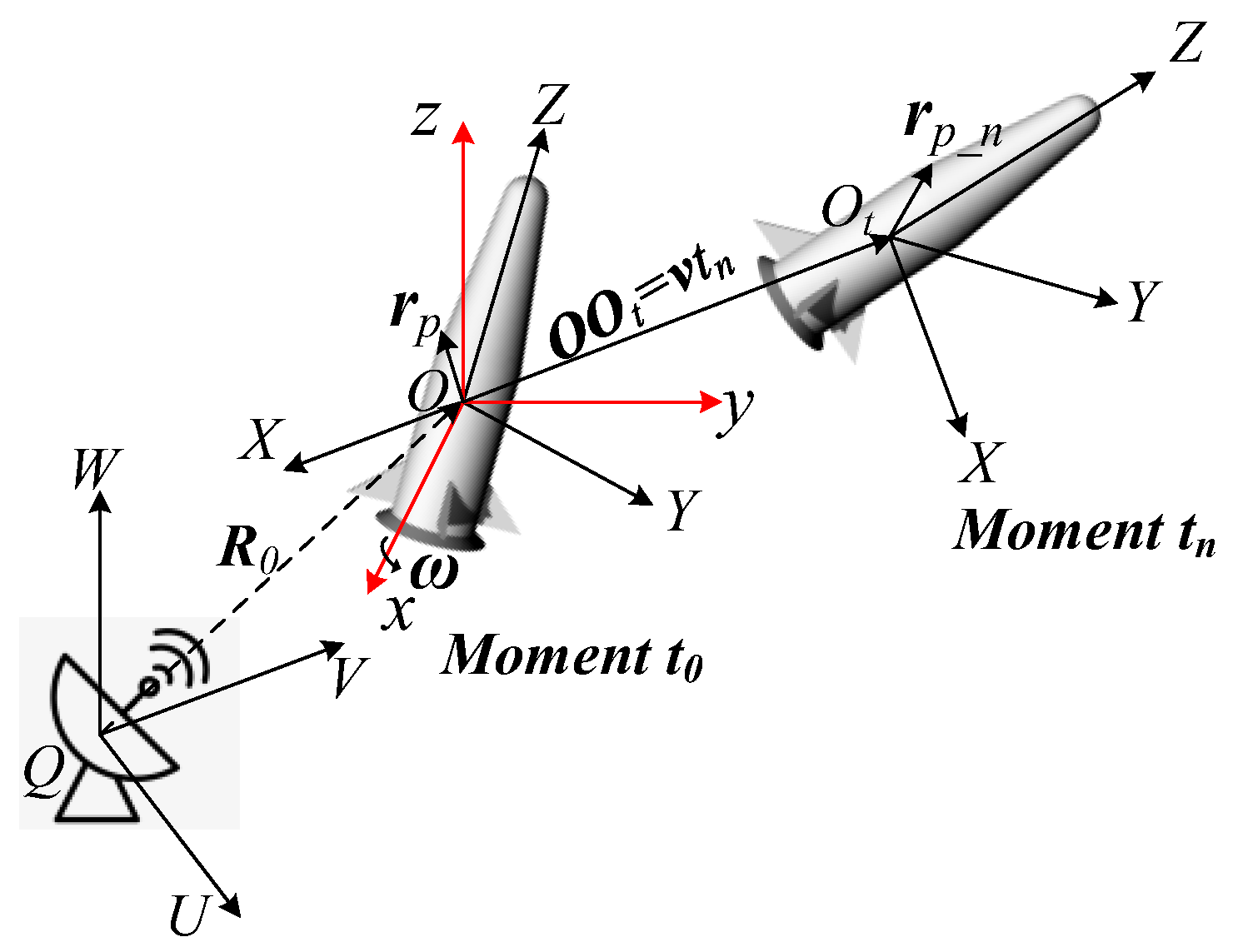
Figure 1. Geometry of moving target with translation and rotation.
Remotesensing 15 05724 g001
Figure 2. (a) Scattering mechanism of SBR method; (b) Dynamic spatial division in LCS.
Remotesensing 15 05724 g002
Figure 3. Flowchart of the dynamic spatial division.
Remotesensing 15 05724 g003
Figure 4. Geometry of illuminated facet with rotation and translation.
Remotesensing 15 05724 g004
Figure 5. Flowchart for solving the scattering field of T r i _ t n .
Remotesensing 15 05724 g005
Figure 6. Bidirectional ray-tracing technology.
Remotesensing 15 05724 g006
Figure 7. Schematic of the sliding window function.
Remotesensing 15 05724 g007
Figure 8. Flowchart of the proposed method. The red dashed box indicates the calculation of the scattering field by the tailored SBR method. The green dashed box indicates the micro-Doppler obtained by the STFT.
Remotesensing 15 05724 g008
Figure 9. Geometric model: (a) Combined model; (b) Wingless missile; (c) Winged missile; (d) Aircraft.
Remotesensing 15 05724 g009
Figure 10. Monostatic RCS of moving target: (a) Dihedral angle; (b) Combined model.
Remotesensing 15 05724 g010
Figure 11. Monostatic RCS of moving target: (a) Trihedral corner reflector; (b) Missile; (c) Aircraft.
Remotesensing 15 05724 g011
Figure 12. Precession of the wingless missile: (ac) Instantaneous HRRPs; (d) Verification of micro-Doppler spectra.
Remotesensing 15 05724 g012
Figure 13. Spin motion of the winged missile, f = 10   GHz   θ i = 90 °   ϕ i = 0 °   VV . (a) Instantaneous HRRP; (b) Verification of micro-Doppler spectra.
Remotesensing 15 05724 g013
Figure 14. Micro-Doppler of the winged missile f = 10   GHz   θ i = 90 °   ϕ i = 0 °   VV . (a) Cone motion; (b) Precession.
Remotesensing 15 05724 g014
Figure 15. Micro-Doppler of the aircraft with flipping motion in different incident angles f = 6   GHz   ϕ i = 0 °   HH . (a) θ i = 90 ° . (b) θ i = 60 ° . (c) θ i = 45 ° . (d) θ i = 30 ° .
Remotesensing 15 05724 g015aRemotesensing 15 05724 g015b
Table 1. Comparison of effectiveness between our method and other solutions.
MLFMM and Our MethodRL-GO and Our Method
μ σ μ σ
Figure 10a0.412.110.362.10
Figure 10b0.582.150.461.99
Figure 11a0.882.170.531.81
Figure 11b0.782.810.571.67
Table 2. Computation cost comparison between our method and other solutions in Figure 10 and Figure 11.
Number
of
Facets
MLFMM
(8 Threads)
RL-GO
(8 Threads)
Traditional SBR
(1 Thread)
Our Method
(1 Thread)
Speedup
Figure 10a16,4926.74 min1.93 min1.01 min0.63 min1.60
Figure 10b71,560306.6 min13.83 min7.47 min3.22 min2.32
Figure 11a12,7864.81 min1.27 min0.96 min0.56 min1.71
Figure 11b148,552488.3 min34.16 min29.2 min6.31 min4.63
Figure 11c248,880//41.97 min7.49 min5.60
Disclaimer/Publisher’s Note: The statements, opinions and data contained in all publications are solely those of the individual author(s) and contributor(s) and not of MDPI and/or the editor(s). MDPI and/or the editor(s) disclaim responsibility for any injury to people or property resulting from any ideas, methods, instructions or products referred to in the content.