1. Introduction
In recent decades, inverse synthetic aperture radar (ISAR) has received a lot of interest because it enables high-resolution two-dimensional imaging of airborne targets at all hours and in all weather situations [
1,
2]. Meanwhile, ISAR is widely used in military air defense and anti-missile applications for target-feature extraction and recognition [
3]. Therefore, ISAR jamming research to prevent targets from being detected and recognized has drawn increasing attention in the electronic countermeasure community [
4,
5].
Digital radio frequency memory (DRFM) technology intercepts radar echoes and processes them with time-frequency modulation to generate false targets for deception jamming [
6,
7,
8]. In [
6], the DRFM principles of high-speed sampling and digital memory are discussed, which are used to store radio frequency and microwave signals. In [
7], the radar signal distortion is estimated and corrected using an improved digital finite impulse response filter with complex coefficients. In [
8], an all-digital image synthesizer is designed to generate false target images. In [
9], a deceptive jamming method is proposed to create false targets with multiple ranges by intercepting radar signals and transmitting back with a different time-delay. Another paper [
10] proposed an FDA-MIMO deception jamming method of modulating the intercepted radar signals with diversification in frequencies, waveforms, and time modulation. The paper [
11] proposed a two-dimensional square-shaped blanket jamming method using frequency modulation and coded phase modulation. This synthesizer can modulate the phase samples of intercepted ISAR pulses, which are stored in DRFM.
Interrupted-sampling repeater jamming (ISRJ) is a method based on DRFM that can generate dense false targets or striped targets for jamming [
12,
13,
14,
15]. In [
12], the principles and the ways of achieving ISRJ are shown to generate multiple false targets for dechirping radar. In [
13], an improved ISRJ method, which can sample and store the radar radio signal at low frequency in the DRFM to preserve its coherent property, was shown to generate a series of false targets before the true target. In [
14], a non-uniform periodic repeater jamming method is shown to generate many false targets with different amplitudes and intervals. In [
15], a constraints parameter ISRJ method is proposed for use against intra-pulse-frequency-agile waveforms. The constraints parameter is calculated by time-frequency ridge extraction and wavelet transform. This class of methods has been widely used in electronic countermeasures. However, the obvious features of dense, similar targets and strips can easily reveal that the radar has suffered from artificial jamming signals. Then, various anti-jamming techniques can be used to filter out the jamming signals [
16,
17]. One paper [
16] proposed an anti-jamming filter method based on the characteristic time-frequency differences between the target echo and the ISRJ signal. Another paper [
17] proposed an anti-jamming method based on the MSMD-net, which utilized the time-domain discontinuity and phase information of ISRJ to perform target-feature extraction and signal reconstruction. Therefore, the research has practical applications for confusing the radar so that it incorrectly identifies the target and cannot detect the jamming.
Sub-Nyquist sampling jamming is a special type of ISRJ in which the width of the sampling pulse is close to the radar sampling pulse. In [
18], the principle of sub-Nyquist sampling jamming is presented to show that lower sampling rates can lead to multiple high-resolution false targets. This technology has significantly decreased the sampling rate and processing-time demands. Combined with ISAR image theory, sub-Nyquist sampling jamming can induce a series of realistic false targets with the same energy amplitude and the same shape on ISAR images [
19,
20,
21,
22]. In [
19,
20], the sub-Nyquist sampling jamming signals are processed via the Compress Sensing (CS) method to obtain finer resolution, realistic multiple false targets. In [
21], an improved DIS method is proposed based on adding the polyphase code to the pulse and sub-Nyquist sampling the echo along the range direction. In [
22], a parallel convolution jamming method is proposed, which samples the radar signal with a sub-Nyquist sampling rate and combines it with a high-resolution range profile.
By generating different shapes of false targets, the radar operator will be confused and misdirected by the false target. The commonly used methods are convolutional modulation jamming [
23], electromagnetic model jamming [
24,
25,
26], and template-modulated jamming [
27,
28]. In [
23], a simple real-time jamming method was proposed, which reduces the computation structure by parallel convolution of the intercepted radar pulse and the real target HRRP. In [
24], an equivalent facet model of targets is proposed to transmit a jamming signal by modulating with the intercepted radar signal. This model can simulate the ISAR images and radar back-scattering of moving targets. In [
25], an imaging technique based on an electromagnetic model is presented, in which a 3-D model is created, triangular facets are divided up, and facet RCS is predicted. In [
26], an electromagnetic model-based jamming method is proposed, which can generate verisimilar false targets, including multiple scattering and shadowing. However, convolutional modulation and electromagnetic model methods generally have high computational complexity and poor real-time performance. Another paper [
27] proposes a real-time jamming algorithm based on a 2-D template for generating realistic false targets by multiplying a derived matrix based on the improved two-stage digital false-target image synthesizer (DIS). In contrast, the scatter positions of the false target cannot be precisely determined on the ISAR image. In [
28], an improved 2-D template jamming method is proposed, fully analyzing the frequency-shift and time-delay relationship between the intercepted LFM pulse and the real target echo. The paper [
29] proposed a deceptive jamming method based on one-bit quantization technology, which can decompose harmonics by a single-frequency threshold. However, those deceptive jamming methods generate a single realistic false target with details. It is important to generate multiple realistic false targets with different target shapes.
This paper proposes a multiple-false-target-generating method based on sub-Nyquist sampling jamming and template multiplication modulated time-delay jamming. Firstly, the jammer intercepts the real target echo and samples it at a sub-Nyquist sampling rate, and then transmits it to a radar receiver. During this process, the incidence and reflection angles of the signal are zero, which means that the echo intercepted by the jammer is the same as the real-target echo received by the radar receiver. Thus, the sub-Nyquist jamming signal will induce multiple false targets with the same shape and energy on ISAR images. At the same time as the sub-Nyquist jamming signal, the LFM pulse is intercepted by the jammer and modulated with a false target template. The frequency-shift relationship between the LFM pulse and the sub-Nyquist sampling jamming signal is analyzed in detail. The jamming signal, which can induce and eliminate scatterers at the specified location of the ISAR image, will be transmitted, and the shape of specified false targets will be changed. Thus, multiple false targets with different ISAR shapes are generated. Adjusting the sub-Nyquist sampling period will adaptively change the number of false targets. Meanwhile, the resolution of the shape changes and the sub-Nyquist false target will alter with the different radar pulse resolutions. These advantages can help to more effectively confuse radar discriminators.
The structure of this paper is organized as follows: In
Section 2, the sub-Nyquist sampling ISAR imaging model is demonstrated.
Section 3 details the procedure and principle of the improved multiple-false-target-generating method.
Section 4 presents numerous simulations. Finally, the conclusion is reported in
Section 5.
2. Sub-Nyquist ISAR Imaging Model
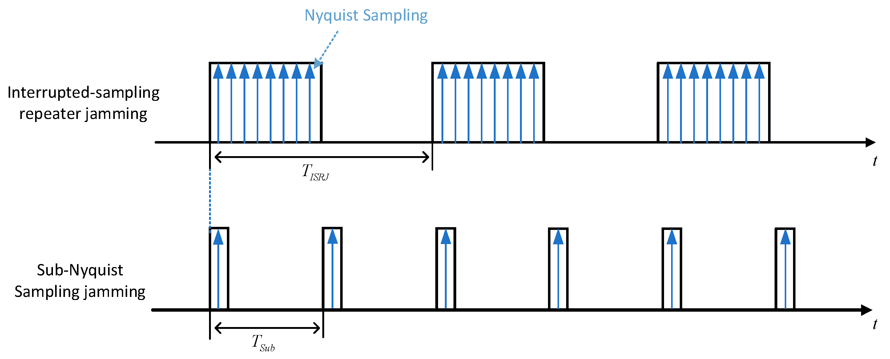
ISRJ is conducted by intercepting a radar signal with high fidelity on a jammer and then forwarding it to the radar receiver. The mathematical expression of ISRJ consists of a series of periodic rectangular pulses as [
18]
where
indicates the sampling pulse width,
is the sampling period, and
is a rectangle envelope pulse, which is
for
.The sub-Nyquist sampling signal is a special type of ISRJ. The difference between them is the sampling pulse width. The sampling rate of the intercepted section of ISRJ still satisfies the Nyquist Sampling Theorem. In contrast, the sub-Nyquist sampling signal is sampled with a much shorter pulse width, which is almost the same as the jammer signal sampling pulse width, as shown in
Figure 1. While both sampling methods can induce multiple, identical false targets, the primary middle false target energy of the ISRJ is stronger, while the sub-Nyquist sampling signal produces multiple false targets with the same energy [
14].
Combining ISAR imaging theory and the sub-Nyquist sampling signal can induce a series of identical ISAR false targets. The jamming characteristics of the sub-Nyquist sampling signals are discussed below. The radar-reflected echoes of a moving target are sampled at fast time and slow time, respectively, and the sub-Nyquist sampling signal is denoted as
where
is the fast time,
indicates the sampling period in the fast time,
is the sampling pulse width in the fast-time domain,
is the slow time,
indicates the sampling period in the slow-time domain, and
is the sampling pulse width in the slow time.
According to the knowledge of the signal system, the sub-Nyquist signals of fast and slow time can be expanded by the Fourier series as
where
is sampling frequency in the fast-time domain,
is sampling frequency in the fast-time domain. The LFM signal transmitted by the radar is
where
is the chirp rate, and
refers to the radar carrier frequency.
Assuming that the scattering coefficients of the target are constant at one, the jammer intercepted the reflection echo of scatters with the sub-Nyquist sampling in the fast and slow time domains, and then transmitted it to the radar receiver. The sub-Nyquist sampling reflection echo of scatters
of the target can be represented as
where
is the propagation range of the scatterer
,
is the pulse duration, and
is the speed of light. When the target moves in a uniform linear motion, the phase compensation under complex motion is not considered. Thus, the echo of scatterers can be processed to the ISAR image at the radar receiver based on the turntable model [
24]. By selecting a reference point on the target, the signal reflected back from this reference point can be expressed as
where
is the reference range. After de-chirping, the received jamming signal can be expressed as
where
,
. Substitute the Equation (3) into Equation (7), and perform the Fourier transform on the fast time
, compensate two phase terms of residual video phase (RVP) and oblique envelope term, then the one-dimensional high-resolution range profile (HRRP) [
19] of the sub-Nyquist jamming signal of scatterers is obtained. Assume that the coordinates of the scatterer
on the turntable model are
. When the target is moving on the turntable model with a tiny angle, there exists an approximate relationship
[
30]. Considering the approximate relationship and
pulse-echoes, the HRRP sum can be expressed as
where
is the scattering coefficient, and
represents the angular velocity of the moving target on the turntable model. Compensating for the constant phase term, and substituting the expression
in Equation (3) into Equation (8), then the jamming signal can be obtained by performing the Fourier transform on the slow time [
19], as
The resulting Doppler shifts in the ISAR image along the azimuth direction and range direction can be expressed as
Since there is a relationship between the Doppler shift and the distance offset as
Bringing Equation (10) into Equation (11), the position coordinates of the sub-Nyquist sampling jamming signal along the range direction and azimuth direction can be obtained, respectively, in the ISAR image as
From Equation (12), it can be seen that the scatterer coordinates of the sub-Nyquist jamming signal have appeared periodically along the range direction and the azimuth direction with the intervals and ,respectively, and the positions of the different false targets are controlled by and , respectively.
3. Template Multiplication Modulated/Time-Delay Jamming Signal
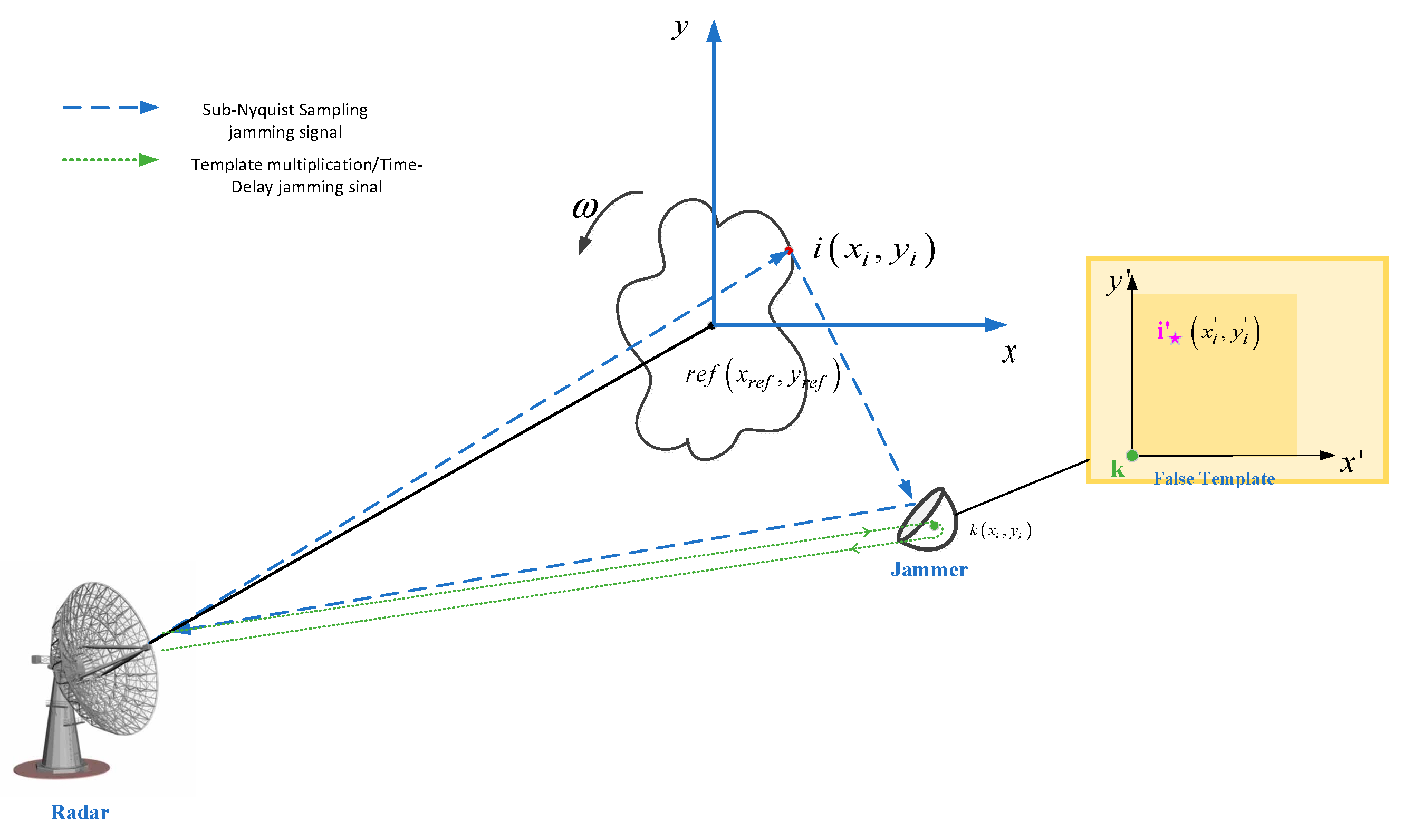
The jammer transmits two types of jamming signals during the jamming process: (1) The sub-Nyquist jamming signal; (2) the template multiplication modulated/time-delay jamming signal, which is transmitted by the jammer based on the false target template, as shown in
Figure 2. The target is rotating counterclockwise at an angular velocity
in the equivalent turntable model, and the position of the scatterer in the coordinate system (i.e., in the turntable model) with the target reference point as the origin is
, while the position of the jammer
is denoted as
. Meanwhile, the equivalent position of scatterer
in the false template is
. The form of the template multiplication modulated/time-delay jamming signal is derived below.
3.1. Template Multiplication Modulated Jamming Signal
According to Equation (12), the sub-Nyquist sampling jamming signal can induce multiple false targets which are identical and equally spaced on the ISAR image. In order to change the shape of the selected false target, the jammer needs to shift the frequency of the intercepted LFM signal and forward it to the radar receiver. The received jamming signal can induce an added scatterer at a specific location on the ISAR image. Assuming that the radar is transmitting an LFM signal, the form of the shift frequency jamming signal should be
where
and
denote the frequency shift parameters along the range and azimuth direction, respectively. These two parameters determine the position of the false target on the ISAR image along the distance and azimuth directions as
. In order to change the ISAR shape of the false target by adding a point at the desired location, the correspondence between the frequency shift parameters and the point on the false target template should be deduced. The frequency shift parameters
and
will be derived below.
The radar receiver receives the template multiplication modulated jamming signal from the jammer in the form of
where
refers to the path of the reflected echo from the scatterer k at the point where the jammer is located. Since the radar performs the same processing on the target echo signal and the jamming signal, the reference point echo signal of Equation (6) is used to de-chirp the jamming signal as
where
indicates the distance between the scatterer
at the jammer’s location and the reference center. By performing an FFT transform on the fast-time and the compensating phase term of RVP and the oblique envelope, the HRRP of the jamming signal can be obtained. Considering the
pulse echoes, the HRRP of
pulse echoes are summed and FFT is conducted on the slow-time of the equation. After neglecting the constant phase, the two-dimensional ISAR image of the jamming signal can be obtained as
where the phase term can be neglected as a constant term. It can be seen that the coordinates of the false-target scatterers induced by the received jamming signal along the range and azimuth directions are
Since the slow time can be regarded as a constant in a single echo, there exists an approximate relationship between the scatterer coordinate and the distance as .
To induce the scatterers at the specific locations in the ISAR image, the positions of the scatterers, which are induced by the template multiplication modulated jamming signal, should be the same as the added scatterers’ position in the sub-Nyquist sampling jamming signal [
28]. Assuming that scatterer
needs to be added, and making Equation (17) equal to Equation (14), then the shift frequency of LFM at the jammer can be obtained as
It can be deduced from Equations (17) and (18) that the template multiplication modulated jamming signal can be processed to generate scatterers in the ISAR image at .
3.2. Time Delay Eliminating Signal
To change the ISAR shape feature of the sub-Nyquist sampling false target, the signal that can eliminate some false target scatterers should be generated in conjunction with the template multiplication modulated jamming signal.
As shown in
Figure 2, the real position of the eliminated scatterer in the ISAR image is
. Assuming that the position of the eliminated scatterer in the fake-target template is
, it should be the same as the position in the fake-target template for eliminating, i.e.,
.
As the phase change of target motion has been assumed to be compensated, the position of the reference point in the coordinate system, which originates in the radar, is
. Therefore, the distance reflected by the real scatterer location
and the jammer location
are denoted by
and
, respectively.
Thus, the time difference between the reflected echoes from the jammer location
and the real scatter location
can be expressed as
. Disregarding the jammer hardware delay, when the LFM signal is captured and then forwarded according to the time delay of the false target template, the cancellation signal can be expressed as
This signal can eliminate a single false-target scatterer. According to Equation (10), the sub-Nyquist jamming signal induces a series of false targets in the ISAR image identical to the real target and equally spaced. Thus, the cancellation signal should consider the distance between the false targets, and it is necessary to shift frequency along the range direction and the azimuth direction. The cancellation signal can be expressed as
Bringing
into Equation (21), the jamming signal received at the radar receiver can be obtained as
The echo has the same amplitude and opposite phase as the real echo returned from scatterer . After frequency shift along the range and azimuth direction, the sub-Nyquist sampling signal corresponding to the false-target scatterer can be eliminated.
3.3. Jamming Signal Generation Process
In order for the jamming signal to induce realistic multiple false targets with different shape characteristics on the ISAR image, the jammer needs to transmit three types of jamming signals: sub-Nyquist sampling jamming signals, template multiplication modulated jamming signals and time-delay cancellation signals. The generation process of the jamming signals is shown in
Figure 3.
3.3.1. Sub-Nyquist Jamming Signal
Firstly, the jammer intercepts the target-reflected echo of the LFM. Secondly, it needs to determine the sub-Nyquist period according to the false-target number to be presented on the target ISAR image, i.e.,
where
denotes the bandwidth of the radar signal,
denotes the pulse repetition period of the radar,
and
denote the signal sampling pulses along the range and azimuth direction, respectively, and
and
denote the number of false targets along the range and azimuth direction, respectively. When the sub-Nyquist sampling signal pulse width of the jammer is close to that of the radar receiver, the energy amplitude of the multiple false targets will be the same. Therefore, the sub-Nyquist pulse width is set as the same as the radar signal sampling pulse width, which can be calculated by estimating the radar bandwidth.
3.3.2. Template Multiplication Modulated Jamming Signal
It is easy to see from
Section 3.1 that when the jammer transmits the jamming signal as in Equation (12), and where the phase-compensated frequency-shift parameters
and
have been derived and obtained as in Equation (12), a false target scatter at the corresponding location on the ISAR image will be induced. Equation (12) has more phase terms than Equation (4) as
where
.This is the phase shift for inducing false scatter, which should be generated by the jammer based on a false template. The generation process of phase shift includes the three steps below [
27]: (1) Performing a two-dimensional FFT on the false target template. (2) Compensation for frequency-shifted phases. (3) Interval sampling on the compensated template.
Firstly, Performing a two-dimensional FFT on the false target template
.
is the distance profile, and
is the azimuth profile. This false target template is the difference operation between the real-target scatter model
and the false-target scatter model
as
where
and
denote the scatters of the two templates over each other, respectively. The eliminating scatter point template
includes the scatter points which need to be eliminated on the ISAR image, and the added scatter point template
includes the scatter points which needs to be added on ISAR image. They are used as target templates for modification of the ISAR shape features, i.e.,
and
.
Set the pixel of template
as
, the resolution along the range and azimuth are
and
, respectively, then
represents the range length and
represents the azimuth length. If the center of the template is set as the origin of the ISAR image, the coordinates of the scatter
of the template
on the ISAR image equal to
. Thus, the false-target template
is transformed by 2-D FFT as
where
and
.
is the number of FFT transforms along the range direction, and
is the number of FFT transforms along the azimuth direction.
Next, Equation (26) is compensated with the frequency-shifted phase by multiplying by a correction matrix
which is
Then the frequency domain expression of the false template can be obtained as
Thirdly, the template
in Equation (28) is processed, sampling with equal intervals as
where
represents the sampling rate of the A/D device on the jammer. If the sampling interval is not an integer, linear interpolation can be used to compensate. There is correspondence between the fast time and range profile
, and the correspondence between the fast time and azimuth profile
. Due to the equal sampling intervals of the templates, the relationship can also be expressed as
, and
. By substituting these relationships in Equation (29), we can obtain
Bringing it into Equation (28), the false template can be obtained, which can be multiplied by the LFM pulse for the template multiplication modulated jamming signal.
3.3.3. Time-Delay Eliminating Signal
Firstly, the comparison between the false-target template and the real-target template is used to calculate the amount of time delay, which can be used for generating the individual-target scatter-cancellation signal. Secondly, the frequency shift is applied to the generated individual-target scatter-cancellation signal, based on the interval between the false targets induced by the sub-Nyquist sampling jamming signal. Finally, the generated jamming signal is transmitted to the radar receiver.
It should be noted that the improved proposed method did not use the ISAR image of the sub-Nyquist sampling false-target directly as a template to generate the time-delay cancellation signal. The cancellation signal is generated by adding shift frequency to the target scatter-cancellation signal.
This can utilize the known jamming signal parameters at the jammer, which can adjust the phases of the time-delay cancellation signal flexibly based on the known sub-Nyquist sampling false-target intervals. Thus, the two types of jamming signals can cooperate, reducing the parameter estimation accuracy and improving the jammer’s efficiency in generating jamming signals.
4. Simulations
The simulation parameters of the radar imaging and the jammer are shown in
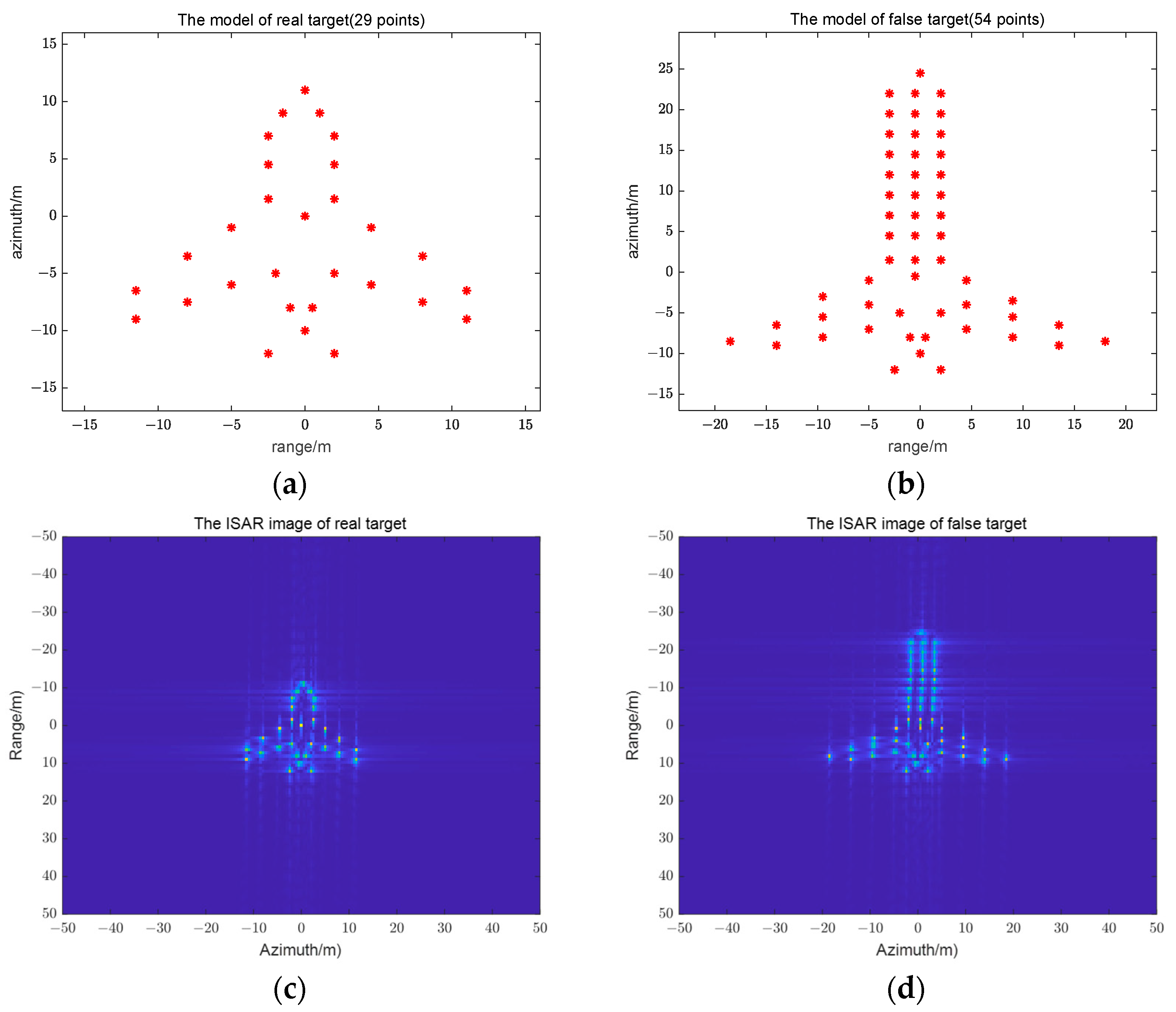
Table 1. In order to analyze whether the proposed jamming method can generate the sub-Nyquist sampling jamming, as well as the feature-shape changes of the specified false targets, this section adopts the 29-point scatter model as the real-target aircraft (
Figure 4a), and the 54-point scatter model as the false-target aircraft (
Figure 4b). The red asterisks in
Figure 4a,b represent the scatterer of the aircraft.
Figure 4c,d show the ISAR images of these two models.
The adding scatter point template (i.e.,
) and the eliminating scatter point template (i.e.,
) are obtained by processing the ISAR image of the real target and that of the false target, as shown in
Figure 4c,d. These two scatter point templates are used for generating the eliminating scatter point jamming signal and the adding scatter point jamming signal, as shown in
Figure 3. These two jamming signals will change the shape of the false target on the ISAR image, which is induced by the sub-Nyquist sampling jamming signal.
4.1. Experiments of Changing Multiple False-Target ISAR Shapes
Based on the theoretical derivation in
Section 3, this section analyzes the effect of the sub-Nyquist sampling jamming signal. The echoes of the 29-point scatter model will be sub-Nyquist sampled and forwarded to the radar receiver. The received jamming signal will induce multiple false targets along the range and azimuth directions on the ISAR image. Then the proposed template multiplication modulated/time-delay method can generate a jamming signal to add scatterers, and cancel existing scatterers, to change the target ISAR shape.
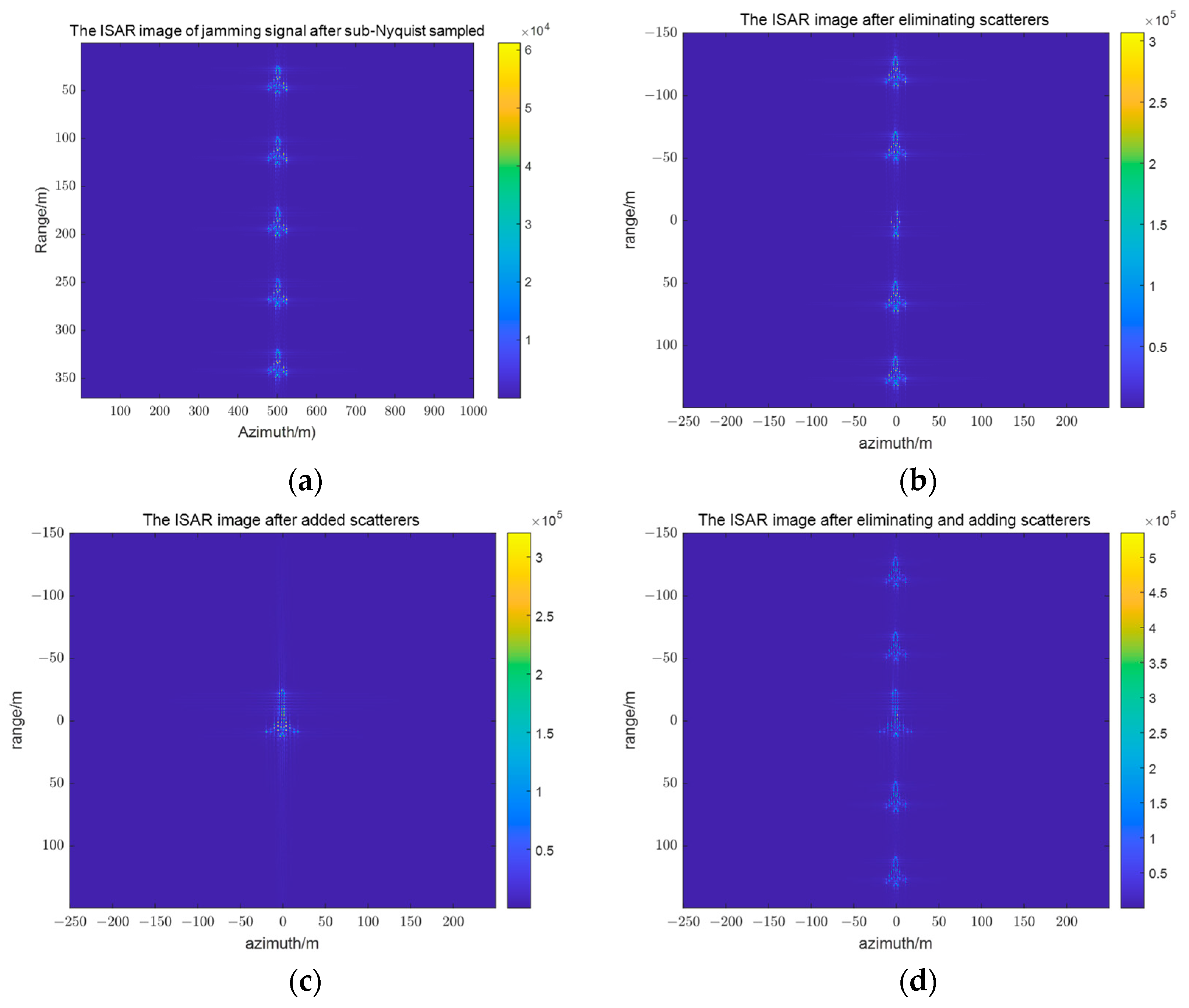
Figure 5a shows the ISAR image of sub-Nyquist sampling jamming signal of the real-target reflected echo in the fast-time domains. This jamming signal induces a series of realistic and identical false targets along the range direction. According to the characteristics of the sub-Nyquist sampling jamming signal, the center false target overlaps with the original real target.
Figure 5b shows the ISAR image after the jamming signal cancels the center-target scatterer, generated by an improved time-delayed eliminating method. The parameter
controls the shifted frequency, which corresponds to the sub-Nyquist sampling false target, to perform the scatterer elimination. The center target corresponds to
. The first false target on the upper side of the center false target corresponds to
. Similarly, the first false target on the lower side of the center false target corresponds to
, and so on.
Figure 5c shows the ISAR image of the adding scatterer, induced by the improved template multiplication modulated jamming signal, at the position of the center target.
Figure 5d shows the ISAR image of the center target after adding and eliminating scatterers. It can be easily seen that the 29-point real target has been changed to the 54-point false target.
Figure 5e shows the ISAR image after the first target scatterer is canceled.
Figure 5f shows the ISAR image after the first target has added scatterers and eliminated scatterers, and parameters are set as
.
Figure 6a shows the ISAR image of the sub-Nyquist sampling jamming signal for the real-target reflected echo in the slow-time domains. This jamming signal induces a series of realistic and identical false targets along the azimuth direction.
Figure 6b shows the ISAR image after the jamming signal cancels the center target scatterer, which is generated by an improved time-delayed cancellation method. The parameter
controls the shifted frequency to perform the scatterer elimination. The center target corresponds to
. The first false target on the left side of the center false target corresponds to
. Similarly, the first false target on the right side of the center false target corresponds to
, and so on.
Figure 6c shows the ISAR image of the center target after adding scatterers and eliminating scatterers.
Figure 6d shows the ISAR image after the fifth target has added scatterers and eliminated scatterers
.
To verify the jamming effect of the sub-Nyquist sampling jamming signal at both fast and slow time domains,
Figure 7 shows that the jammer intercepts the target-reflected echo with sub-Nyquist sampling both in fast and slow times and changes the ISAR shape features of the specified false targets.
Figure 7a demonstrates that the sub-Nyquist jamming signal induces
realistic false targets with the same energy at equal intervals along the range and azimuth directions.
Figure 7b shows the ISAR image after the jamming signal eliminates the scatterer at the specified false target (row 3, column 4), with the parameter
and
. These parameters control the selected position of the false target as row 3, column 4.
Figure 7c shows the ISAR image of the scatterer that needs to be added at the specified location and
Figure 7d shows the ISAR image after the shape-change of the specified false target. Thus, the improved jamming method can generate multiple realistic false targets and autonomously change the ISAR shape of the specified false targets.
4.2. Parameter Analysis
The sub-Nyquist jamming signal can induce multiple false targets in the ISAR image, and the number and interval of the false targets can change with the different parameters. At the same time, the pulse parameters will change according to the imaging requirements, which are not controllable by the jammer, such as the radar resolution. Therefore, this section analyzes the jamming effect with different parameters.
4.2.1. The Experiments with Different Sub-Nyquist Periods
Figure 8 shows the effect of changing the false target ISAR shape after sub-Nyquist sampling in the fast-time domain with different sampling periods. In
Figure 8a, the sub-Nyquist period along the range direction is set as
. Since the sampling pulse width is
, the multiplicity is expressed as
, and there are three identically realistic false targets along the range direction. In
Figure 8b, the sub-Nyquist period is set as
, the multiplicity is expressed as
, and there are five identically realistic false targets along the range direction. In
Figure 8c, the sub-Nyquist period is set as
, the multiplicity is expressed as
, and there are seven identically realistic false targets along the range direction. Thus, the number of false targets can be controlled according to the multiplicity relationship between the sub-Nyquist sampling period and sampling pulse width. Meanwhile, the shape-change parameter is set as
, and the ISAR shape of the first false target on the side of the center target can be changed.
Figure 9 below shows the HRRP with different false target numbers along the range direction. It shows that the number of false targets is controlled by the sub-Nyquist period. Corresponding to the three false targets along the azimuth range in
Figure 8a, there are also three targets in the HRRP in
Figure 9a. When the first target is changed (count from up to down) on the ISAR image in the
Figure 8a, the first targets on the right on the HRRP are different from the other targets too. Corresponding to the five false targets along the azimuth range in
Figure 8b, there are also five targets in the HRRP in
Figure 9b. When the second target is changed (count from up to down) on the ISAR image, the second targets on the right on the HRRP are different from the other targets too. Corresponding to the seven false targets along the azimuth range in
Figure 8c, there are also seven targets in the HRRP in
Figure 8c. The HRRP results verify that the proposed method can generate multiple false targets and change the shape of the false targets.
Figure 10 shows the effect of changing the false-target ISAR shape after sub-Nyquist sampling in the slow-time domain with different sampling periods. In
Figure 10a, the sub-Nyquist period along the azimuth direction is set as
. Since the radar’s pulse repetition period is
, the multiplicity exists as
, and there are three identically realistic false targets along the range direction. In
Figure 10b, the sub-Nyquist period is set as
, the multiplicity exists as
, and there are five identically realistic false targets along the range direction. In
Figure 10c, the sub-Nyquist period is set as
, the multiplicity exists as
, and there are seven identically realistic false targets along the range direction. Thus, the number of false targets can be controlled according to the multiplicity relationship between the sub-Nyquist sampling and the pulse repetition periods. Meanwhile, the shape-change parameter is set as
, and the ISAR shape of the first false target on the side of the center target can be changed. As seen in
Figure 8 and
Figure 9, the proposed method can flexibly alter the false target feature and change the sub-Nyquist periods of fast and slow time.
4.2.2. The Experiments with Different Radar Resolutions
Figure 11 illustrates the jamming effect of jamming signals with different radar resolutions. The radar bandwidth is set to
, the imaging times are set to
, and the pulse repetition frequency is set to
. The parameter is set as
and
to control the shape of false targets in row 3, column 4. From
Figure 11a–c, it can be found that with the higher radar resolution, the ISAR images of the sub-Nyquist false targets are clearer, and the altered shape feature of false targets in row 3 and column 4 is clearer too. Therefore, the proposed jamming method applies to radars with different resolutions.
4.2.3. The Experiments with Different Locating Estimation Accuracies
Figure 12 illustrates the jamming effect of eliminating scatterers with different estimating accuracies at different false targets. The locating estimation accuracies are set as
. From
Figure 12a–c, with the higher position estimation error, the scatterer elimination of the false targets in row 3 and column 4 is worse, and the shape of the original targets is retained more, while the un-eliminated scatterer in the false targets is not very obvious in comparison with the large size of the overall ISAR image. Thus, a more effective deception can still be achieved by the added scatterers of the false targets.
4.2.4. The Experiments with Different SNRs
In order to verify its robustness, the proposed method is simulated with different SNRs, which is the power ratio between the real target’s echo and white noise. The jammer intercepted the mixed signal of the real target’s echo and white noise, sampled the mixed signal with sub-Nyquist, then forwarded it to the radar receiver.
Figure 13 illustrates the jamming effect of eliminating and adding scatterers with different SNRs. The SNRs are set as
, respectively. The radar bandwidth is set as
, and the imaging times were set to
. The sub-Nyquist periods are set as
, and
.The parameters are set as
and
to control the shape of false targets in row 3, column 4. From
Figure 12a to
Figure 13c, the false targets are submerged on the ISAR image with the higher SNRs, while the shape of the false targets in row 3 and column 4 can also be changed. Thus, a better deception effect can still be achieved by the added scatterers of the false targets.
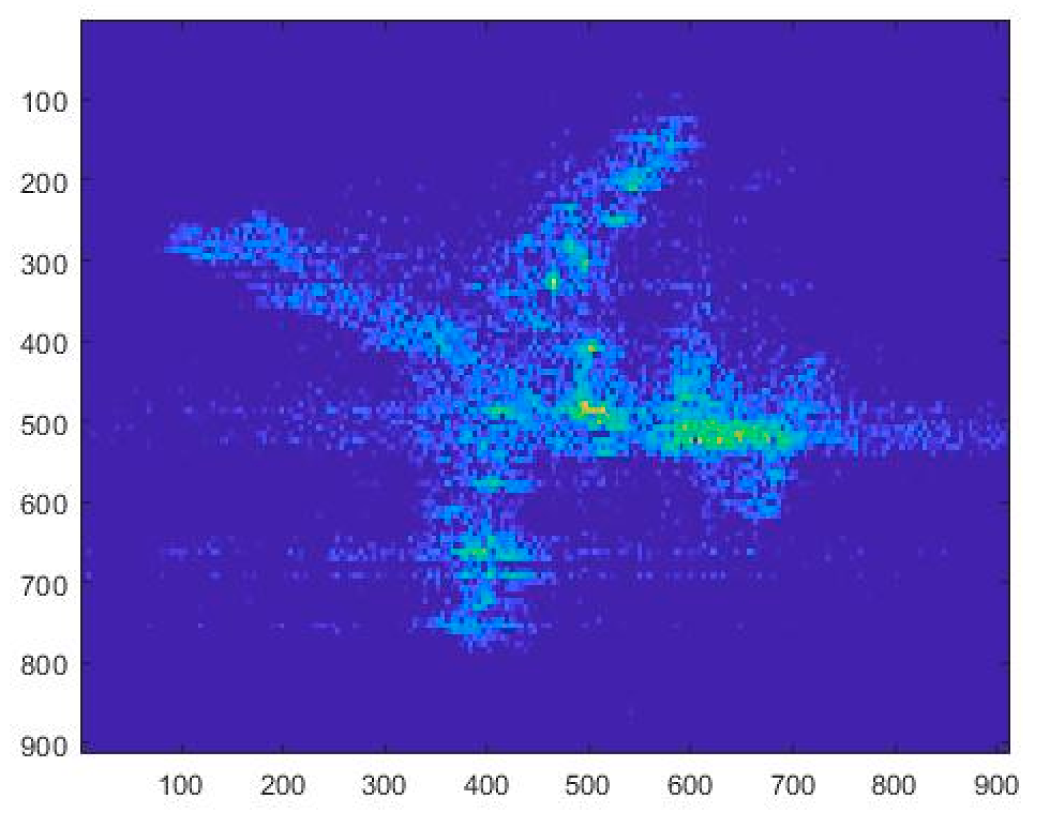
4.3. The Experiment with Maneuvering Block-Targets
In order to verify the utility of the proposed method for maneuvering block-targets’ echo data, the ISAR image of a Yak-42 aircraft, which owns hundreds of scatterers and varying scattering coefficients, is used as a false-target template in this section, as shown in
Figure 14.
4.3.1. The Experiments with Different Radar Resolutions
Figure 15 illustrates the jamming effect of jamming signals with different radar resolutions. The ISAR image of a Yak-42 aircraft is set as the false-target template. The radar bandwidth is set to
, the imaging times are set to
, and the pulse repetition frequency is set to
. The parameter is set as
and
to control the shape of the false targets in row 3, column 4. From
Figure 15a–c, it can be found that with the higher radar resolution, the ISAR image of the sub-Nyquist false targets is clearer, and the altered shape feature of the false targets in row 3 and column 4 is clearer too. Therefore, the proposed jamming method applies to the real-target template with different radar resolutions.
4.3.2. The Experiments with Different SNRs
Figure 16 illustrates the jamming effect of eliminating and adding scatterers with different SNRs. The SNRs are set as
, respectively. The radar bandwidth is set to
, and the imaging times were set to
. The sub-Nyquist period is set as
,
.The parameter is set as
and
to control the shape of the false targets in row 3, column 4. From
Figure 16a–c, the false targets are submerged on the ISAR image with the higher SNRs, while the shape of the false targets in row 3 and column 4 can also be changed. Thus, a better deception effect can still be achieved as long as the SNR does not exceed
.


 ,
, 


