Abstract
Spherical images have the advantage of recording full scenes using only one camera exposure and have been becoming an important data source for 3D reconstruction. However, geometric distortions inevitably exist due to the spherical camera imaging model. Thus, this study proposes a reliable feature matching algorithm for spherical images via the combination of local geometric rectification and CNN (convolutional neural network) learned descriptor. First, image patches around keypoints are reprojected to their corresponding tangent planes based on a spherical camera imaging model, which uses scale and orientation data from the keypoints to achieve both rotation and scale invariance. Second, feature descriptors are then calculated from the rectified image patches by using a pre-trained separate detector and descriptor learning network, which improves the discriminability by exploiting the high representation learning ability of the CNN. Finally, after classical feature matching with the ratio test and cross check, refined matches are obtained based on an essential matrix-based epipolar geometry constraint for outlier removal. By using three real spherical images and an incremental structure from motion (SfM) engine, the proposed algorithm is verified and compared in terms of feature matching and image orientation. The experiment results demonstrate that the geometric distortions can be efficiently reduced from rectified image patches, and the increased ratio of the match numbers ranges from 26.8% to 73.9%. For SfM-based spherical image orientation, the proposed algorithm provides reliable feature matches to achieve complete reconstruction with comparative accuracy.
1. Introduction
Image-based 3D reconstruction has become a critical module in recent photogrammetric systems [1], which has been adopted in varying applications ranging from conventional digital urban construction [2] to the recent archaeological excavation [3] and transmission corridor inspection [4]. Because of the low cost of imaging sensors and the maturity of processing techniques, perspective cameras are the most widely used instruments for data acquisition in image-based 3D reconstruction, especially for aerial photogrammetry. With the increasing demands for 3D reconstruction for street or indoor environments, perspective cameras become inefficient and non-applicable for data acquisition. The main reason is that their limited FOV (field of view) causes significantly more image recording burden to cover the omnidirectional scene.
In contrast to the limited FOV of perspective cameras, spherical cameras, also known as omnidirectional cameras, have the advantage of recording full scenes using only one camera exposure, as they have respectively 360° and 180° FOV in the horizontal and vertical directions [5]. Except for professional spherical cameras, e.g., the LadyBug series that is widely used in mobile mapping systems (MMSs) [6], recent years have also witnessed the explosive development of consumer-grade spherical cameras that feature low costs and light weights, e.g., the Insta360 and Ricoh Theta [7]. For image-based 3D reconstruction, the capability and popularity of spherical cameras have promoted their usage in varying fields, including, but not limited to, damaged building evaluation [8], urban 3D modeling [9] and tunnel rapid mapping [10]. Thus, spherical images are becoming an important data source for 3D reconstruction.
Feature matching is the prerequisite to implementing image-based 3D reconstruction. In the literature, feature matching has been achieved through local feature-based image matching methods that compute descriptors for image patches around detected keypoints and cast image matching as searching nearest neighbors among two sets of descriptors. The pipeline of local feature-based image matching consists of two major steps, i.e., feature detection and matching based on the well-designed descriptors [11,12], and outlier removal based on photometric and geometric constraints [13]. Existing research has promoted the development of feature matching techniques toward the direction of automation and precision. However, the vast majority of existing algorithms are used for perspective images, which differ from spherical images in the camera imaging model [14]. Perspective images use a 2D plane imaging model that projects 3D scene points to 2D image points on the image plane. On the contrary, spherical images are recorded by projecting scene points onto the 3D sphere, which are further flattened to the 2D image plane. Because of the transformation from the 3D sphere to the 2D plane, geometric distortions are inevitably introduced into the recorded spherical images, which become more and more serious in the regions near the equator to the poles [15] as shown in Figure 1. Thus, more attention should be paid to reducing distortions in spherical images.
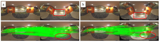
Figure 1.
The illustration of geometric distortion in the spherical images. (a,b) indicate image pairs that are rotated around the X axis with the angles of 45° and 75°, respectively. The red rectangles and ellipses show increasing distortions and decreasing matches.
In the literature, both 2D plane and 3D sphere-based algorithms have been documented to alleviate the geometric distortions in spherical images [16,17,18]. For 2D plane-based methods, existing solutions can be divided into three groups, i.e., global methods, semi-global methods, and local methods. In global methods, Wang et al. [18] have implemented a SLAM (simultaneous localization and mapping) system, namely CubemapSLAM, in which the cubic-map reprojection solution is used to convert each spherical image into six perspective images that are then processed by using classical feature matching methods. Considering the distribution pattern of image geometric distortions, Taira et al. [17] aimed to execute feature matching on the region near the sphere equator, which is achieved by rotating spherical images around the Y axis and detecting local features from the regions near the equator. Compared with the global cubic-map reprojection solution, it can be seen as a semi-global rectification method. In contrast to the global and semi-global rectification solutions, Chuang and Perng [16] proposed reprojecting the local image patches of keypoints onto the corresponding tangent planes and calculating feature descriptors from rectified image patches. Except for rectification-based methods, other research achieves feature detection and descriptor computation by considering the principle of the spherical imaging model. The proposed solutions are usually designed on the spherical grid for neighbor searching, such as SPHORB [19] and BRISKS [20], instead of the plane grid used in the classical methods. In the above-mentioned solutions, classical heuristic algorithms are widely used for feature detection and description.
In recent years, CNN (convolutional neural network)-based deep learning networks have also been widely used for feature matching due to their powerful representation learning ability [21,22]. According to network tasks, existing CNNs can be divided into three groups, i.e., joint feature and metric learning networks that learn the similarity of image patches [23,24], separate detector and descriptor learning networks that learn to compute descriptors [25,26], and joint detector and descriptor learning networks that learn to detect keypoints and compute descriptors [27,28]. These CNN models have achieved comparative or superior performance for feature matching of perspective images. To avoid the degenerated performance for spherical images, recent research has also attempted to design CNNs that can adapt to geometric distortions in spherical images. The reported solutions can be divided into three groups, i.e., tangent projection methods, CNN kernel shape resizing methods, and CNN sampling point adjustment methods. For the first one, equirectangular images are first projected to undistorted tangent images [29] or divided into quasi-uniform discrete images [30], and existing CNNs are applied to the resulting images. For the second one, CNNs are designed to work on equirectangular images by adjusting the CNN kernel shape [31,32,33]. In Su and Grauman [32], a CNN termed SPHCONV was proposed to produce results as the output of applying perspective CNNs to the corresponding tangent images. SPHCONV was achieved by defining convolution kernels with varying shapes for pixels in different image rows. Su and Grauman [34] proposed a kernel transformer network (KTN) to learn spherical kernels by taking as input the latitude angle and source kernels for perspective images. For the third one, sampling points of CNN kernels are adjusted based on geometric distortions instead of adjusting the convolution kernel shape. Zhao et al. [33] and Coors et al. [31] designed distortion-aware networks that sample non-regular grid locations according to the distortions of different pixels. The core idea of these networks is to determine the sampling locations based on the spherical projection of a regular grid on the corresponding tangent plane. Due to regular convolution kernels, these frameworks enable the transfer between CNN models for perspective and equirectangular images.
To achieve feature matching for spherical images, both hand-crafted and learning-based methods can provide useful solutions. On the one hand, the redesigned methods can solve the geometric distortions from the camera imaging principle of spherical images. These algorithms, however, cannot leverage existing mature techniques. On the other hand, the methods that use a reprojection strategy can be easily adapted to the algorithms designed for perspective images and cooperated with the representation learning ability of CNNs. Based on the above-mentioned observation, this study proposes a reliable feature matching method for spherical images through the combination of local geometric rectification and CNN learned descriptors. The main contributions are summarized as follows: (1) we design a local geometric rectification algorithm based on the camera imaging model of spherical images and the scale and orientation data from the feature detector; (2) we implement a reliable feature matching workflow for spherical images by using a CNN descriptor learning network for the rectified image patches and a robust essential matrix estimation algorithm for outlier removal in feature matching; and (3) we verify the validation and demonstrate the performance of the proposed solution by using real spherical images in the terms of feature matching and SfM (structure from motion)-based image orientation.
This paper is organized as follows. Section 2 presents the details of the proposed feature matching algorithm, including local geometric rectification, deep learning-based descriptor generation, and outlier removal via essential matrix estimation. Section 3 gives the details of the used datasets and experimental analysis and comparison for feature matching and SfM-based image orientation. Finally, Section 5 presents the conclusions and future studies.
2. Methodology
Figure 2 presents the overall workflow of the proposed algorithm and verification solution. It mainly consists of three steps. First, SIFT (scale invariant feature transform) [12] keypoints are detected mainly because of their wide usage in industrial fields, and the image patches around them are reprojected for local geometric rectification; second, feature descriptors are then calculated from rectified patches based on a pre-trained separate detector and descriptor learning network, which are subsequently fed into the standard SIFT matching module with cross-check and ratio-test constraints; third, refined matches are obtained after outlier removal by using the geometric constraint via the essential matrix estimation. In this study, the proposed algorithm is finally verified in feature matching and SfM-based image orientation by using three real spherical images, which are captured from varying environments and different platforms. The details of the implementation are presented in the following subsections.
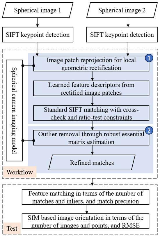
Figure 2.
The overall workflow of the proposed algorithm and verification solution.
2.1. Spherical Camera Imaging Model
The camera imaging model defines the geometric relationship between 3D scene points in the object space and their corresponding 2D image points in the image plane. In the literature, the widely used spherical camera imaging model can be categorized into three major groups, i.e., unified camera model [35], general camera model [36], and multi-camera model [37]. Due to the wide usage of multi-camera imaging instruments and the simple formula of the imaging model, the unit sphere camera model that belongs to the multi-camera model is adopted in this study for feature matching and SfM-based image orientation. For the unit sphere camera model, the intrinsic parameters K of a sphere camera include three parameters without other distortion parameters, including one for the focal length f and two for the principal point . Generally, the radius r of the unit sphere camera model is set as one. In other words, the focal length of the spherical camera is set as ; the principal point coordinates are fixed at the center of images, i.e., and , in which W and H indicate the image width and height, respectively.
Based on the definition of the spherical camera imaging model, the imaging procedure from the 3D scene points to 2D image points can be illustrated in Figure 3, in which the spherical image is represented in the equirectangular projection (ERP) format. For the imaging procedure, Figure 3a presents the spherical camera imaging model that maps one 3D point P in the object space to the 3D point p on the sphere. Figure 3b shows the transformation between the 3D point p and its corresponding 2D point in the image plane. In this projection, the point p on the unit sphere can be formulated in two coordinate systems, i.e., the geographic coordinate system and Cartesian coordinate system . In the former, the coordinate of point p is represented using the longitude and latitude ; in the latter, the coordinate of point p is represented using three coordinate terms .
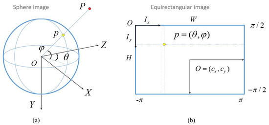
Figure 3.
The principle of spherical camera imaging model and coordinate transformation: (a) the spherical camera imaging model; (b) the coordinate transformation between the spherical image and equirectangular image [5].
According to the coordinate system definition, the transformation from the geographic coordinate system to the Cartesian coordinate system can be expressed by using Equation (1), in which the sphere radius . In addition, the transformation between 3D geographic coordinates and 2D image coordinates can be formulated as Equation (2), where and are the image coordinates in the ERP image plane. These two equations establish the coordinate transformation between 3D sphere points and 2D image points and form the basic formulas for the subsequent local geometric rectification and outlier removal:
2.2. Image Patch Reprojection for Local Geometric Rectification
The geometric distortion in the spherical image seriously degenerates the repeatability of local features due to the appearance difference of image patches around detected keypoints. In this study, image patch reprojection is used to achieve local geometric rectification and alleviate the geometric distortions. The core of image patch reprojection is to project the original patch on the sphere to the corresponding patch on the tangent plane that goes through the keypoint in the geographic coordinate system . The principle of image patch reprojection is illustrated in Figure 4. For the keypoint detected from the ERP spherical image, as shown in Figure 4a, its corresponding geographic coordinate , as presented in Figure 4b, is first calculated according to Equation (2). By using the normal vector that starts from the origin O to the sphere point p, a tangent plane is then defined as shown by the red line in Figure 4b. Based on the imaging geometry, the local patch around p can be projected onto the tangent plane and generate the rectified patch, as shown in Figure 4c.
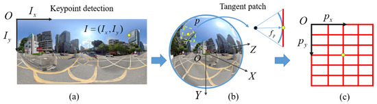
Figure 4.
The illustration of image patch reprojection for local geometric rectification: (a) the keypoint detected from the ERP spherical image; (b) the position of the keypoint is transformed to the spherical coordinate system, in which the tangent plane is defined; (c) the image grid defined on the tangent plane.
In the above-mentioned reprojection procedure, the scale and orientation parameters should be carefully determined to define image patches since it ensures the scale and rotation invariant for descriptors. Fortunately, the required data can be obtained from widely used feature detection algorithms. In the context of feature detection using SIFT, a feature point f can be represented as , in which indicates the pixel coordinates; and indicate the scale and orientation parameters, respectively. Suppose that the desired width and height of the rectified patch are labeled as and , respectively, for the original image scale. Thus, the patch size for the feature point p can be calculated using Equation (3), in which is the scale ratio between the pyramid layers of the feature point p and the original image. Generally, can be calculated as . For the SIFT used in this study, the original image scale is set as :
Based on the defined patch size, a pinhole camera model for the rectified patch is defined with the focal length and principal point and to ensure the same spatial resolution as the original spherical image. In this study, an inverse procedure is utilized to generate the rectified image patch to ensure the desired dimension of output patches. The rectified image patch is computed based on the following steps:
- (1)
- (2)
- Considering that a unit sphere camera model is used to define the Cartesian coordinate system , the homogeneous coordinate is then projected onto the sphere point through the normalization operation presented in Equation (5):
- (3)
- The sphere point is further transformed from the local Cartesian coordinate system of the rectified image patch to the global Cartesian coordinate system by using a transformation matrix , as presented by Equation (6). The transformation matrices , and define the rotation around the Z, X, and Y axes with the orientation , latitude and longitude , respectively:
- (4)
Based on the above-mentioned procedure, the rectified image patches with the size of and can be generated based on the tangent plane reprojection, which is finally resized to the dimension of and . Noticeably, in step (3), the rotation around the Z axis indicates the transformation from the major orientation of feature point f to the nominal orientation of the Cartesian coordinate system. It is used to achieve the orientation invariant for the subsequently generated descriptors.
2.3. Learned Feature Descriptors from Rectified Image Patches
The rectified image patches are then used to compute descriptors for feature matching. In this study, a separate detector and descriptor learning network is adopted due to two main reasons. On the one hand, image patches are the input of the network, which differs from that for the joint detector and descriptor learning network; on the other hand, this strategy can be easily integrated into the existing workflow for the subsequent feature matching and SfM-based image orientation, instead of the joint feature and metric learning network.
Considering the performance of the existing separate detector and descriptor learning networks [22], a pre-trained HardNet [38] network is selected for the descriptor calculation. Figure 5 shows the network structure and sampling strategy in network training. The network is the same as L2-Net [26]. It consists of seven CNN layers with batch normalization and ReLU activation, except for the last layer without activation. To obtain multi-scale information, the dilated convolution is used in the third and fifth layers. For an input image patch with a size of 32 by 32 pixels, HardNet outputs a 128D descriptor with the same dimension as the widely used SIFT descriptor. In contrast to L2-Net, HardNet adopts a hard negative sampling strategy and triplet margin loss function for network training, which further enhances the discriminative ability of the network. Thus, by using the HardNet network, 128D descriptors are calculated from the rectified image patches and used for the subsequent feature matching.
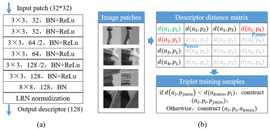
Figure 5.
The network structure and sampling strategy of HardNet: (a) the network structure of HardNet; (b) the sampling strategy used in network training.
2.4. Outlier Removal through Robust Essential Matrix Estimation
To establish correspondence between two images, the initial matches are first obtained based on the standard feature matching strategy. The nearest and second-nearest neighbor searching is executed between two sets of feature descriptors, and the feature points that pass through the ratio test are set as candidate matches. Meanwhile, the cross-checking strategy is also used to further refine the initial matches.
Due to repetitive patterns in images and the limited discriminative ability of local descriptors, false matches are inevitably retained in the initial matches. In this study, the coplanar geometric constraint is utilized to refine the initial matches, which requires that three vectors, i.e., the baseline vector that connects projection centers and two observing vectors that start from projection centers to the scene point, are coplanar. Suppose that the relative orientation of two spherical images is expressed by the relative rotation R and translation T; the intrinsic parameter K of the spherical camera are known. Therefore, an essential matrix can be calculated to encode the relative orientation. For two corresponding rays and , the coplanar constraint is then formulated by Equation (7):
where and are the spherical coordinates of two corresponding image points and in the image plane, which are calculated according to Equations (1) and (2). The geometrical meaning of the coplanar constraint is shown in Figure 6. If and are a true match, the three vectors , and T are coplanar. In other words, lies on the circular plane composed of the vector and T with the normal vector . Thus, using the estimated essential matrix E, false matches can be identified from the initial matches.
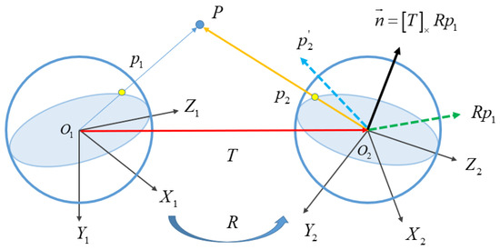
Figure 6.
The principle of relative orientation for spherical images.
To achieve a robust estimation of the essential matrix E, the RANSAC-based hypothesis-verify framework [39] is used in this study. During the iteration in RANSAC, the error metric e and error threshold are required to label true and false matches. According to the coplanar constraint as shown in Figure 6, the corresponding ray of in the left image lies on the circular plane that is defined by the normal vector and the projection center of the right image. Thus, this study adopts the vector-to-plane geodesic angular error metric [14] as presented in Equation (8):
where indicates the absolute value. At the same time, the error threshold in the unit of pixels is converted to spherical angles in the unit of degrees. In this study, the conversion is implemented according to Equation (9):
where indicates the scale factor of these two metrics; is the error threshold in the spherical angles. In conclusion, based on the estimated essential matrix E, the corresponding points and are labeled as one inlier if the angular error . Based on the coplanar constraint, refined matches are obtained from the initial matches.
2.5. Implementation of the Proposed Algorithm
The proposed algorithm is implemented by using the C++ programming language. For SIFT feature detection, the open-source library SIFTGPU [40] with default parameter settings is used due to its hardware-accelerated high efficiency. For descriptor learning, the pre-trained HardNet network released on the official website is directly used due to two main reasons. On the one hand, it is trained using the Brown and HPatches datasets, which have large diversity in terms of viewpoint and illumination; on the other hand, this study aims to achieve feature matching using geometric rectified patches, instead of using spherical images directly. Thus, no retraining is necessary for the utilized network. For nearest neighbor searching-based feature matching, the maximum distance and the ratio test threshold are set as 0.7 and 0.8, respectively. For essential matrix estimation, the 8-point algorithm [41] is used, in which eight corresponding points form eight linear equations, and the linear system is then solved through SVD (singular value decomposition) [42]. In addition, the error threshold is set as 4 pixels.
3. Experiments and Results
In the experiments, three datasets are utilized to evaluate the performance of the proposed algorithm for the feature matching of spherical images. First, the adopted datasets and evaluation metrics are described. Second, the comparison with other algorithms is conducted for feature matching in terms of the number of matches and inliers and the matching precision. Third, the proposed algorithm is integrated with an incremental SfM workflow for image orientation. In this study, all tests are conducted on a Windows desktop computer that is configured with 32 GB memory, an Intel Core i7-8700K 3.7 GHz CPU (central processing unit), and an NVIDIA GeForce GTX 1050Ti GPU (graph processing unit).
3.1. Test Sites and Datasets
Detailed information on the three spherical datasets is presented in Table 1. The datasets are captured by using both consumer-grade and professional sphere cameras, which are fixed on the ground or in a hand-held tripod and mounted on the moving car. The characteristic of each test site and the details for data acquisition are listed as follows.

Table 1.
Detailed information of the three spherical datasets.
- The first dataset is recorded from a campus, which includes a parterre surrounded by high buildings as shown in Figure 7a. For image acquisition, a Garmin VIRB 360 camera is used, which stores images in the equirectangular representation format. The data acquisition is conducted around the central parterre, and there are a total number of 37 images collected with a resolution of 5640 by 2820 pixels.
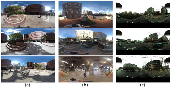 Figure 7. The illustration samples of the used spherical datasets: (a) dataset 1; (b) dataset 2; (c) dataset 3.
 - The second dataset includes a complex building structure that covers from its rooftop to the inner aisles as shown in Figure 7b. Parterres exist on the rooftop, and the inner aisles connect different layers. For image acquisition, the same Garmin VIRB 360 camera as in dataset 1 is adopted by using a hand-held tripod. A total number of 279 spherical images are collected, which cover the whole inner aisles.
- The third dataset is collected using an MMS system. The test site goes along an urban street, whose length is approximately 7.0 km. Along the street, low residual buildings are located near the two roadsides as shown in Figure 7c. In this test site, a PointGrey Ladybug3 camera that is made of six fisheye cameras is used. By setting the interval distance of 3 m for camera exposure, there are a total number of 1937 spherical images collected from this site.
3.2. Evaluation Metrics
The proposed algorithm would be evaluated in feature matching and SfM-based image orientation. For feature matching, three metrics are utilized, i.e., the number of matches and inliers, and matching precision. The first indicates the number of obtained initial matches; the second indicates the total number of obtained true matches; the third represents the number ratio of true matches and initial matches. In SfM-based image orientation, the obtained matches are then fed into an incremental SfM engine to reconstruct camera poses and scene points. For performance evaluation, three metrics are used, i.e., the number of images and points, and RMSE (root mean square error). The first and second metrics indicate the completeness of the image orientation, which is calculated as the number of registered images and reconstructed 3D points. The third metric is calculated as the reprojection error in BA (bundle adjustment) optimization. The description of used evaluation metrics is listed in Table 2.
Table 2.
The description of the used metrics for performance evaluation. Categories 1 and 2 indicate the terms of feature matching and SfM-based image orientation, respectively. RMSE represents the root mean square error in BA optimization.
3.3. The Analysis of the Performance for Local Geometric Rectification
Local geometric rectification via image patch reprojection is the first step in the proposed algorithm. It aims to alleviate appearance differences caused by the spherical camera model. For visual analysis, Figure 8 presents the image patches that are directly cropped from images and geometrically rectified based on tangent plane projection, which are rendered by yellow and green colors, respectively. It is clearly shown that geometric distortions exist in original image patches, such as the curve boundaries of buildings. After geometric rectification, the distortions can be decreased, especially for the regions near the poles.
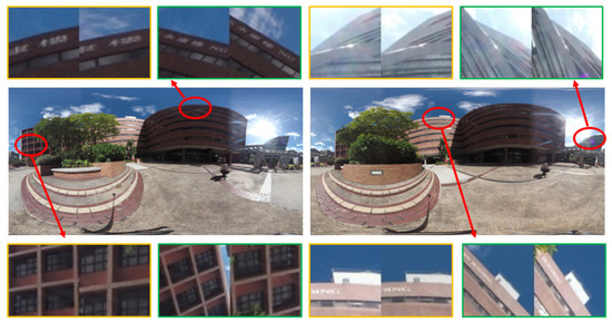
Figure 8.
The comparison of extracted local image patches from one image pair in dataset 1. For each item, the left and right items are directly cropped around keypoints and geometrically rectified based on tangent plane reprojection, respectively.
In local geometric rectification, the orientation and scale of the output image patches have a great influence on the performance of the subsequent descriptor calculation. In this study, the scale and orientation are obtained from the used SIFT keypoint detectors. Figure 9 shows the comparison of local geometric rectification under different configurations. The geometric rectification can dramatically decrease the appearance differences as the results are presented from Figure 9a to Figure 9b. Although they have high appearance similarity, the generated image patches are not invariant to the changes in orientation and scale. By using the orientation and scale from detected SIFT features, the image patches are then rotated and scaled accordingly as illustrated in Figure 9c,d, respectively. For the visual analysis of the proposed algorithm, Figure 10 illustrates the generated image patches from dataset 3. We can see that the structure and texture of generated patches from the proposed algorithm are more regular as verified by the patches labeled by the red rectangle.
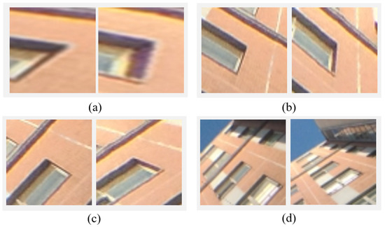
Figure 9.
The comparison of local geometric rectification: the image patch (a) directly cropped from the spherical image without geometric rectification; (b) without orientation and scale; (c) with only orientation; and (d) with both orientation and scale. Noticeably, the image size is 32 by 32 pixels for all patches.
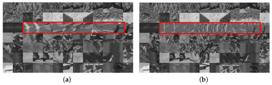
Figure 10.
The illustration of generated image patches: image patch (a) directly cropped from the spherical image without geometric rectification and (b) rectified by the proposed algorithm. The red rectangle indicates the effect of geometric rectification.
To verify the validation of the proposed local geometric rectification solution, three image pairs with varying viewpoints are selected from dataset 2 for tests, and the four configurations presented in Figure 9 are used for image patch extraction and feature matching. The statistical results of the number of inliers are shown in Figure 11, in which the methods with labels 1, 2, 3, and 4 correspond to the four configurations in Figure 9a–d. It is shown that for all three image pairs, the number of inliers increases obviously for the methods with the label from 1 to 4. For a visual illustration, Figure 12 presents the matching results of image pair 2. We can see that the geometric rectification increase matches near poles as shown in Figure 12b; the introduction of orientation and scale further increases matches over the whole image plane as presented in Figure 12c,d.
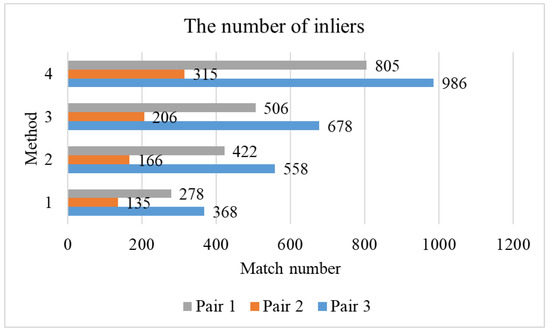
Figure 11.
The comparison of the number of inliers of different methods.
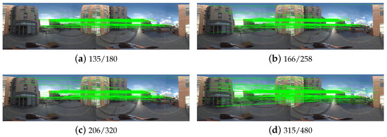
Figure 12.
The comparison of different image patch extraction methods for feature matching: image patch (a) directly cropped from the spherical image without geometric rectification; geometrically rectified (b) without orientation and scale; (c) with only orientation; and (d) with both orientation and scale.
3.4. The Comparison of Local Feature-Based Matching
Local feature-based matching is then conducted by using the geometrically rectified image patches. In this test, three metrics are used for performance evaluation, including the number of matches, the number of inliers, and match precision. For comparison analysis, four methods are adopted in this study, i.e., SIFT, ASLFeat, NGR-H (HardNet for non-geometric rectified patches), and the proposed algorithm (HardNet for geometric rectified patches). SIFT is used as the baseline algorithm, which has been widely used in the photogrammetry field. ASLFeat is an end-to-end network for feature detection and description [28]. NGR-H is utilized to verify the advantage of deep learning-based descriptors when compared with hand-crafted descriptors. Before feature matching, image pairs are first selected based on the sequential and spatial constraints in the data acquisition. For the three datasets, there are a total number of 157, 4941, and 14,836 image match pairs.
Table 3 presents the statistical results of feature matching for the three datasets. It is shown that compared with separated detection and description methods, i.e., SIFT and NGR-H, the proposed algorithm achieves the best performance under all used metrics, except for the matching precision in dataset 1. In particular, compared with SIFT, the increasing ratio of the number of inliers is 73.9% for dataset 1, which is higher than the values of 34.2% and 26.8% for datasets 2 and 3, respectively. The main reason is that the top region of the images is covered by sky and cloud, as illustrated in Figure 7, and few keypoints are extracted from the region with large distortions. When comparing SIFT and NGR-H, we can see that NGR-H achieves better performance in dataset 1 and comparative performance in datasets 2 and 3. It verifies that the learned descriptor has a high tolerance to image distortions. For the end-to-end network ASLFeat, the number of inliers is obviously lower than the proposed method, which are 83, 198, and 177 for the three datasets, respectively. The main reason is the low position accuracy of detected keypoints from down-sampled feature maps as mentioned in [22].
Table 3.
The statistical results of feature matching for the tested algorithms. The mean of each metric is calculated from all selected image pairs for feature matching. The best values are in bold.
For the further visual analysis, Figure 13, Figure 14 and Figure 15 show the matching results of one selected image pair from the three datasets. We can see that the proposed algorithm achieves the best performance in the number of matches and inliers. In the term of match precision, comparative performance can be observed from image pairs 1 and 3 for the three methods. For image pair 2, the proposed algorithm has better performance to cope with the large distorted regions. Due to the low position accuracy, the number of inliers and match precision of ASLFeat is obviously lower than the other methods. Considering the performance of the evaluated methods, only SIFT, NGR-H, and the proposed algorithm would be further analyzed in the following experiments.
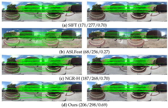
Figure 13.
The comparison of feature matching for dataset 1. For each method, the left and right images represent the results of initial and refined matches. The values in the bracket are the number of inliers and initial matches, and the match precision, respectively.
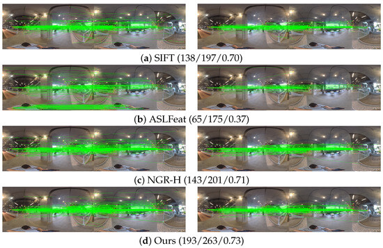
Figure 14.
The comparison of feature matching for dataset 2. For each method, the left and right images represent the results of initial and refined matches. The values in the bracket are the number of inliers and initial matches, and the match precision, respectively.
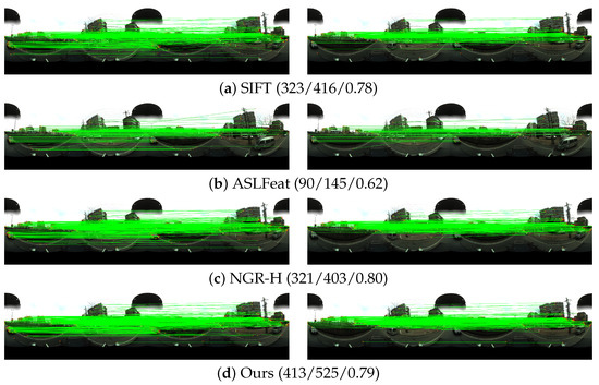
Figure 15.
The comparison of feature matching for dataset 3. For each method, the left and right images represent the results of initial and refined matches. The values in the bracket are the number of inliers and initial matches, and the match precision, respectively.
For the overall statistical analysis, Figure 16 presents the statistical results of the number of inliers by using the frequency histogram and accumulative frequency. For each sub-figure, the range of the inlier number is divided into bins with the same width, and the inlier number of all selected image pairs votes for the bins and the accumulative frequency. For interpretation, the point near the value of 90% in the accumulative frequency is highlighted in each sub-figure, and the range of bins and inliers are labeled. It is shown that for the three datasets, the proposed algorithm has a larger span for both bins and inliers when compared with SIFT and NGR-H. It means that more image pairs have a larger number of inliers.
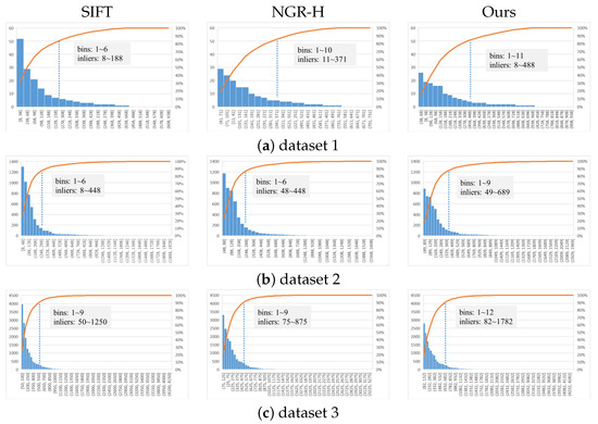
Figure 16.
The statistical analysis of the number of inliers for the three datasets. Each figure presents two terms. The bottom one is the bin frequency that inlier numbers fall into, which is arranged in descending order; the top one indicates the accumulation of the bin frequencies.
3.5. Application in SfM-Based Image Orientation
SfM-based image orientation can be achieved by using the refined feature matches. In our previous work, an incremental SfM engine was designed and implemented [5]. The inputs of the SfM engine are spherical images in the ERP format. After the sequential execution of SIFT feature matching, essential matrix-based outlier removal, and the iterative bundle adjustment, sparse reconstruction can be obtained, including the oriented images and reconstructed 3D points. Based on the established workflow, the proposed feature matching algorithm is integrated with the SfM engine for image orientation.
Table 4 presents the statistical results of image orientation for the three datasets. We can see that all images can be successfully reconstructed for the three test algorithms. The number of reconstructed 3D points from the proposed algorithm are 4645, 49,252, and 363,371 for the three datasets, respectively, whose increase ratios are approximately 80.8%, 22.8%, and 25.2% when compared with SIFT. It is almost consistent with the increased ratio of feature matching as presented in Section 3.4. Considering the metric RMSE in the BA optimization, SIFT achieves better performance than the proposed algorithm, whose values are 0.74, 0.80, and 0.56 for the three datasets, respectively. It can explain from two aspects. On the one hand, fewer matched points would be involved in the BA optimization, which would decrease the ratio of false matches in SIFT; on the other hand, the distortions near the pole are larger than the other regions, which would further decrease the position accuracy of matched points in the proposed algorithm. In addition, Figure 17 presents the image orientation results of the three datasets based on the SfM engine. It is shown that all images in the three datasets are well reconstructed, which can be used for subsequent 3D reconstruction procedures, e.g., dense matching and texture mapping. Based on the comparison, we can conclude that the proposed algorithm can reconstruct more 3D points and achieves comparative accuracy when compared with other methods.
Table 4.
The statistical results of image orientation for the three datasets in terms of the number of oriented images and reconstructed 3D points and precision. The RMSE is in pixels.
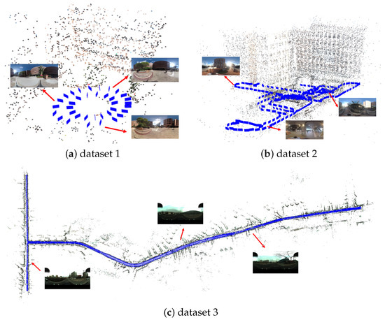
Figure 17.
Image orientation results based on the SfM engine. The blue rectangles indicate the oriented images, and reconstructed 3D points are rendered by the color of the images.
4. Discussion
Spherical images are becoming a promising data source for the 3D reconstruction of complex scenes due to their omnidirectional FOV. However, geometric distortions are inevitably added to the recorded images of their spherical camera imaging model. Considering the wide usage of spherical cameras and their promising applications in 3D reconstruction, this study designs and implements a reliable feature matching method for spherical images. The main purpose is to reduce the geometric distortions that are caused by the projection from the 3D sphere to the 2D plane and improve the discriminative power of descriptors by exploiting deep learning-based techniques. The performance of the proposed algorithm is verified by spherical images captured from both consumer-grade and professional cameras.
Compared with existing methods, two major advantages are designed for the proposed algorithm. On the one hand, local geometric rectification is adopted to remove the distortions. For scale and rotation invariance, it is implemented by considering both orientation ori and scale oriof the output image patches since they have a great influence on the subsequent descriptor calculation. Specifically, the scale ori and orientation ori information in the SIFT keypoint detector is used to improve the performance as demonstrated in Section 3.3. On the other hand, the learned descriptor is then utilized to describe rectified patches because they have shown high discriminative power in recent studies, and the results are verified in Section 3.4. In addition, a robust outlier removal method is designed as the final step to refine the initial matches, which is based on the essential matrix estimation in the sphere coordinate system. Based on the designed feature matching method, reliable feature matches can be used to achieve SfM- and SLAM-based image orientation as shown in Section 3.5.
According to the experimental results, some limitations could also be observed in this study. First, the unit sphere camera model is used for image orientation, which consists of three intrinsic parameters, i.e., one for the focal length f and two for the principal point . The ideal camera model may not be enough to establish the imaging model for consumer-grade cameras. It can be observed from the RMSE presented in Table 4, in which the RMSE of datasets 1 and 2 is larger than that of dataset 3. Second, the hand-crafted SIFT detector is used to detect keypoints for patch generation. However, compared with aerial images, spherical images are often captured from near-ground streets or indoor rooms that include a majority of low- or non-textured regions. Thus, a few keypoints can be detected from these scenes, which can be verified by the results presented in Figure 14. In future studies, more spherical camera imaging models would be compared in the SfM-based image orientation. Furthermore, deep learning-based detector-free networks can be used to address the second issue.
5. Conclusions
This study implements a reliable feature matching algorithm for spherical images via the combination of local geometric rectification and the CNN learned descriptor. After SIFT-based feature detection, image patches are first reprojected to their corresponding tangent planes for the local geometric rectification, which can achieve scale- and orientation-invariant geometric rectification. Using a pre-trained separate detector and descriptor network, feature descriptors are then generated and used to obtain the initial matches. Finally, refined matches are obtained after outlier removal that is implemented using the essential matrix-based epipolar geometry. The performance is verified by using real spherical images, and experimental results demonstrate that the proposed algorithm can provide reliable feature matches and improve the completeness of SfM-based image orientation.
Author Contributions
Conceptualization, S.J. and W.C.; methodology, S.J. and J.L.; software, S.J. and J.L.; validation, J.L., Y.L. and D.W.; formal analysis, J.L.; resources, Y.L.; data curation, S.J.; writing—original draft preparation, S.J. and J.L.; writing—review and editing, S.J. and J.L.; visualization, J.L.; supervision, W.C.; project administration, S.J. and W.C.; funding acquisition, S.J. All authors have read and agreed to the published version of the manuscript.
Funding
This research was funded by the National Natural Science Foundation of China (Grant No. 42371442), the Hubei Provincial Natural Science Foundation of China (Grant No. 2023AFB568), and the Hong Kong Scholars Program (Grant No. 2021-114).
Data Availability Statement
Research data would be shared from e-mail query.
Acknowledgments
The authors would like to thank authors who have made their algorithms of SiftGPU and ColMap free and open-source software packages, which is helpful to the research in this paper. Meanwhile, heartfelt thanks to the anonymous reviewers and the editors, whose comments and advice improve the quality of the work.
Conflicts of Interest
The authors declare no conflict of interest.
References
- Jiang, S.; Jiang, W.; Wang, L. Unmanned Aerial Vehicle-Based Photogrammetric 3D Mapping: A survey of techniques, applications, and challenges. IEEE Geosci. Remote Sens. Mag. 2022, 10, 135–171. [Google Scholar] [CrossRef]
- Wu, B.; Xie, L.; Hu, H.; Zhu, Q.; Yau, E. Integration of aerial oblique imagery and terrestrial imagery for optimized 3D modeling in urban areas. ISPRS J. Photogramm. Remote Sens. 2018, 139, 119–132. [Google Scholar] [CrossRef]
- Chiabrando, F.; D’Andria, F.; Sammartano, G.; Spanò, A. UAV photogrammetry for archaeological site survey. 3D models at the Hierapolis in Phrygia (Turkey). Virtual Archaeol. Rev. 2018, 9, 28–43. [Google Scholar] [CrossRef]
- Jiang, S.; Jiang, W.; Huang, W.; Yang, L. UAV-based oblique photogrammetry for outdoor data acquisition and offsite visual inspection of transmission line. Remote Sens. 2017, 9, 278. [Google Scholar] [CrossRef]
- Jiang, S.; You, K.; Li, Y.; Weng, D.; Chen, W. 3D Reconstruction of Spherical Images based on Incremental Structure from Motion. arXiv 2023, arXiv:2306.12770. [Google Scholar]
- Torii, A.; Havlena, M.; Pajdla, T. From google street view to 3d city models. In Proceedings of the 2009 IEEE 12th International Conference on Computer Vision Workshops, ICCV Workshops, Kyoto, Japan, 29 September–2 October 2009; pp. 2188–2195. [Google Scholar]
- Gao, S.; Yang, K.; Shi, H.; Wang, K.; Bai, J. Review on panoramic imaging and its applications in scene understanding. IEEE Trans. Instrum. Meas. 2022, 71, 1–34. [Google Scholar] [CrossRef]
- Jhan, J.P.; Kerle, N.; Rau, J.Y. Integrating UAV and ground panoramic images for point cloud analysis of damaged building. IEEE Geosci. Remote Sens. Lett. 2021, 19, 1–5. [Google Scholar] [CrossRef]
- Fangi, G.; Pierdicca, R.; Sturari, M.; Malinverni, E. Improving spherical photogrammetry using 360 omni-cameras: Use cases and new applications. Int. Arch. Photogramm. Remote Sens. Spat. Inf. Sci. 2018, 42, 331–337. [Google Scholar] [CrossRef]
- Janiszewski, M.; Torkan, M.; Uotinen, L.; Rinne, M. Rapid photogrammetry with a 360-degree camera for tunnel mapping. Remote Sens. 2022, 14, 5494. [Google Scholar] [CrossRef]
- Bay, H.; Ess, A.; Tuytelaars, T.; Van Gool, L. Speeded-up robust features (SURF). Comput. Vis. Image Underst. 2008, 110, 346–359. [Google Scholar] [CrossRef]
- Lowe, D.G. Distinctive image features from scale-invariant keypoints. Int. J. Comput. Vis. 2004, 60, 91–110. [Google Scholar] [CrossRef]
- Jiang, S.; Jiang, W. Reliable image matching via photometric and geometric constraints structured by Delaunay triangulation. ISPRS J. Photogramm. Remote Sens. 2019, 153, 1–20. [Google Scholar] [CrossRef]
- Pagani, A.; Stricker, D. Structure from motion using full spherical panoramic cameras. In Proceedings of the 2011 IEEE International Conference on Computer Vision Workshops (ICCV Workshops), Barcelona, Spain, 6–13 November 2011; pp. 375–382. [Google Scholar]
- Lichti, D.D.; Jarron, D.; Tredoux, W.; Shahbazi, M.; Radovanovic, R. Geometric modelling and calibration of a spherical camera imaging system. Photogramm. Rec. 2020, 35, 123–142. [Google Scholar] [CrossRef]
- Chuang, T.Y.; Perng, N. Rectified feature matching for spherical panoramic images. Photogramm. Eng. Remote Sens. 2018, 84, 25–32. [Google Scholar] [CrossRef]
- Taira, H.; Inoue, Y.; Torii, A.; Okutomi, M. Robust feature matching for distorted projection by spherical cameras. IPSJ Trans. Comput. Vis. Appl. 2015, 7, 84–88. [Google Scholar] [CrossRef]
- Wang, Y.; Cai, S.; Li, S.J.; Liu, Y.; Guo, Y.; Li, T.; Cheng, M.M. CubemapSLAM: A piecewise-pinhole monocular fisheye SLAM system. In Proceedings of the Asian Conference on Computer Vision, Perth, WA, Australia, 2–6 December 2018; pp. 34–49. [Google Scholar]
- Zhao, Q.; Feng, W.; Wan, L.; Zhang, J. SPHORB: A fast and robust binary feature on the sphere. Int. J. Comput. Vis. 2015, 113, 143–159. [Google Scholar] [CrossRef]
- Guan, H.; Smith, W.A. BRISKS: Binary features for spherical images on a geodesic grid. In Proceedings of the IEEE Conference on Computer Vision and Pattern Recognition, Honolulu, HI, USA, 21–26 July 2017; pp. 4516–4524. [Google Scholar]
- Chen, L.; Rottensteiner, F.; Heipke, C. Feature detection and description for image matching: From hand-crafted design to deep learning. Geo-Spat. Inf. Sci. 2021, 24, 58–74. [Google Scholar] [CrossRef]
- Jiang, S.; Jiang, W.; Guo, B.; Li, L.; Wang, L. Learned local features for structure from motion of uav images: A comparative evaluation. IEEE J. Sel. Top. Appl. Earth Obs. Remote Sens. 2021, 14, 10583–10597. [Google Scholar] [CrossRef]
- Han, X.; Leung, T.; Jia, Y.; Sukthankar, R.; Berg, A.C. Matchnet: Unifying feature and metric learning for patch-based matching. In Proceedings of the IEEE Conference on Computer Vision and Pattern Recognition, Boston, MA, USA, 7–12 June 2015; pp. 3279–3286. [Google Scholar]
- Kumar BG, V.; Carneiro, G.; Reid, I. Learning local image descriptors with deep siamese and triplet convolutional networks by minimising global loss functions. In Proceedings of the IEEE Conference on Computer Vision and Pattern Recognition, Las Vegas, NV, USA, 27–30 June 2016; pp. 5385–5394. [Google Scholar]
- Luo, Z.; Shen, T.; Zhou, L.; Zhu, S.; Zhang, R.; Yao, Y.; Fang, T.; Quan, L. Geodesc: Learning local descriptors by integrating geometry constraints. In Proceedings of the European Conference on Computer Vision (ECCV), Munich, Germany, 8–14 September 2018; pp. 168–183. [Google Scholar]
- Tian, Y.; Fan, B.; Wu, F. L2-net: Deep learning of discriminative patch descriptor in euclidean space. In Proceedings of the IEEE Conference on Computer Vision and Pattern Recognition, Honolulu, HI, USA, 21–26 July 2017; pp. 661–669. [Google Scholar]
- Dusmanu, M.; Rocco, I.; Pajdla, T.; Pollefeys, M.; Sivic, J.; Torii, A.; Sattler, T. D2-net: A trainable cnn for joint description and detection of local features. In Proceedings of the IEEE/CVF Conference on Computer Vision and Pattern Recognition, Long Beach, CA, USA, 15–20 June 2019; pp. 8092–8101. [Google Scholar]
- Luo, Z.; Zhou, L.; Bai, X.; Chen, H.; Zhang, J.; Yao, Y.; Li, S.; Fang, T.; Quan, L. Aslfeat: Learning local features of accurate shape and localization. In Proceedings of the IEEE/CVF Conference on Computer Vision and Pattern Recognition, Seattle, WA, USA, 13–19 June 2020; pp. 6589–6598. [Google Scholar]
- Eder, M.; Shvets, M.; Lim, J.; Frahm, J.M. Tangent images for mitigating spherical distortion. In Proceedings of the IEEE/CVF Conference on Computer Vision and Pattern Recognition, Seattle, WA, USA, 13–19 June 2020; pp. 12426–12434. [Google Scholar]
- Shan, Y.; Li, S. Descriptor matching for a discrete spherical image with a convolutional neural network. IEEE Access 2018, 6, 20748–20755. [Google Scholar] [CrossRef]
- Coors, B.; Condurache, A.P.; Geiger, A. Spherenet: Learning spherical representations for detection and classification in omnidirectional images. In Proceedings of the European Conference on Computer Vision (ECCV), Munich, Germany, 8–14 September 2018; pp. 518–533. [Google Scholar]
- Su, Y.C.; Grauman, K. Learning spherical convolution for fast features from 360 imagery. Adv. Neural Inf. Process. Syst. 2017, 30. [Google Scholar]
- Zhao, Q.; Zhu, C.; Dai, F.; Ma, Y.; Jin, G.; Zhang, Y. Distortion-aware CNNs for Spherical Images. In Proceedings of the International Joint Conference on Artificial Intelligence, Stockholm, Sweden, 13–19 July 2018; pp. 1198–1204. [Google Scholar]
- Su, Y.C.; Grauman, K. Kernel transformer networks for compact spherical convolution. In Proceedings of the IEEE/CVF Conference on Computer Vision and Pattern Recognition, Long Beach, CA, USA, 15–20 June 2019; pp. 9442–9451. [Google Scholar]
- Mei, C.; Rives, P. Single view point omnidirectional camera calibration from planar grids. In Proceedings of the Proceedings 2007 IEEE International Conference on Robotics and Automation, Rome, Italy, 10–14 April 2007; pp. 3945–3950. [Google Scholar]
- Scaramuzza, D.; Martinelli, A.; Siegwart, R. A flexible technique for accurate omnidirectional camera calibration and structure from motion. In Proceedings of the Fourth IEEE International Conference on Computer Vision Systems (ICVS’06), New York, NY, USA, 4–7 January 2006; p. 45. [Google Scholar]
- Ji, S.; Shi, Y.; Shi, Z.; Bao, A.; Li, J.; Yuan, X.; Duan, Y.; Shibasaki, R. Comparison of two panoramic sensor models for precise 3d measurements. Photogramm. Eng. Remote Sens. 2014, 80, 229–238. [Google Scholar] [CrossRef]
- Mishchuk, A.; Mishkin, D.; Radenovic, F.; Matas, J. Working hard to know your neighbor’s margins: Local descriptor learning loss. In Proceedings of the 31st International Conference on Neural Information Processing Systems, Long Beach, CA, USA, 4–9 December 2017; Volume 30. [Google Scholar]
- Fischler, M.A.; Bolles, R.C. Random sample consensus: A paradigm for model fitting with applications to image analysis and automated cartography. Commun. ACM 1981, 24, 381–395. [Google Scholar] [CrossRef]
- Wu, C. SiftGPU: A GPU Implementation of Sift. 2007. Available online: http://cs.unc.edu/~ccwu/siftgpu (accessed on 10 October 2023).
- Hartley, R.; Zisserman, A. Multiple View Geometry in Computer Vision; Cambridge University Press: Cambridge, UK, 2003. [Google Scholar]
- Umeyama, S. Least-squares estimation of transformation parameters between two point patterns. IEEE Trans. Pattern Anal. Mach. Intell. 1991, 13, 376–380. [Google Scholar] [CrossRef]
Disclaimer/Publisher’s Note: The statements, opinions and data contained in all publications are solely those of the individual author(s) and contributor(s) and not of MDPI and/or the editor(s). MDPI and/or the editor(s) disclaim responsibility for any injury to people or property resulting from any ideas, methods, instructions or products referred to in the content. |
© 2023 by the authors. Licensee MDPI, Basel, Switzerland. This article is an open access article distributed under the terms and conditions of the Creative Commons Attribution (CC BY) license (https://creativecommons.org/licenses/by/4.0/).