1. Introduction
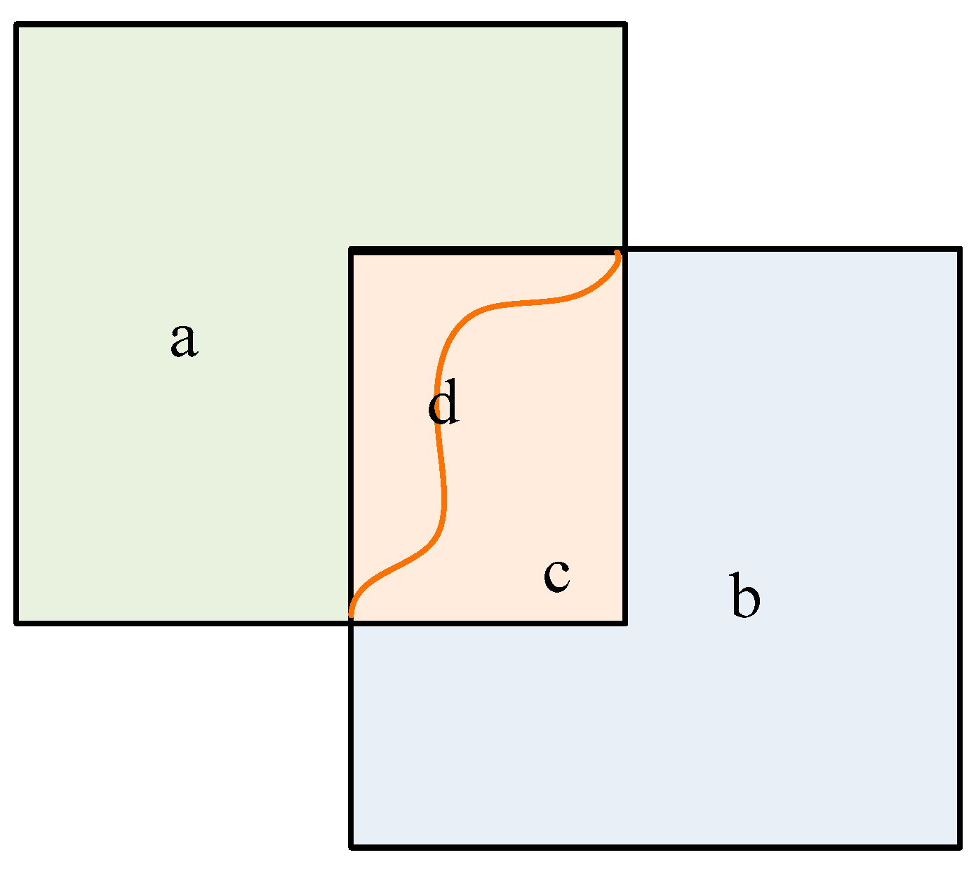
Image mosaicking is defined as the procedure of seamlessly stitching together images that share overlapping regions, creating a unified and coherent image (see
Figure 1) [
1]. Given the wide range of applications for large-scale remote sensing images in fields such as environmental monitoring, resource surveillance, and disaster risk assessment [
2,
3,
4,
5], image mosaicking serves as a vital component of the remote sensing image processing pipeline [
6]. It plays a pivotal role in analyzing and visualizing extensive spatial information captured by remote sensing platforms, enabling the creation of detailed and seamless representations of landscapes. Consequently, it facilitates improved comprehension and decision-making in diverse domains, including agriculture, forestry, environmental monitoring, and urban development.
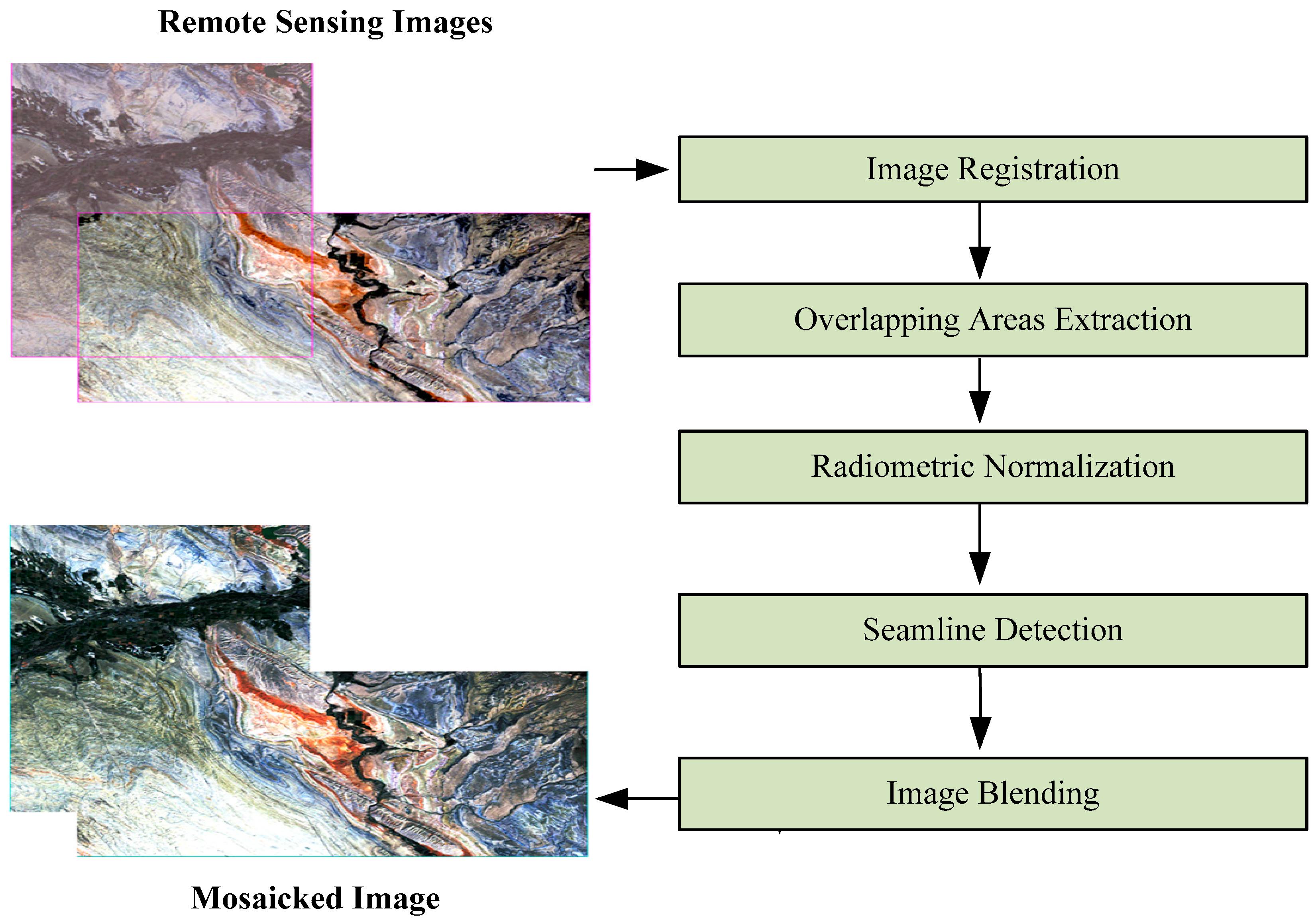
For successful mosaicking, three criteria must be met: (1) consistent geometric shapes of objects in the resulting image, (2) normalized radiation intensity, and (3) seamless transitions and natural connections in overlapping areas. To satisfy these criteria, remote sensing image mosaicking typically involves five steps: image registration, overlapping areas extraction, radiometric normalization, seamline detection, and image blending [
7] (see
Figure 2). Image registration [
8] ensures criterion (1) by matching the same features in different images to keep their geometric shapes consistent. After image registration, extracting the overlapping areas serves as the foundation for subsequent processing. Depending on whether the remote sensing image has spatial geographic reference information, the extraction of overlapping areas can be based on geographic reference [
9] or pixel similarity [
10,
11]. If the images are obtained from varying sensors or in different time periods, the radiation intensity between them may vary, hence leading to an unnatural appearance in the mosaicked result. To preserve criterion (2), radiometric normalization [
12] (also referred to as radiometric balancing or tonal adjustment) computes the radiation mapping relationships for the entire image using overlapping areas. Seamline detection [
13] and image blending [
14] ensure criterion (3). Seamline detection locates the best position for splicing the images, and based on the seamline, image blending reduces differences around the seamline and then integrates them into a cohesive whole.
In some applications, such as disaster monitoring or time-sensitive analysis, there is a need for real-time or near-real-time processing of remote sensing data. However, we can see that remote sensing image mosaicking necessitates significant computing resources and data, especially when dealing with high-resolution or multispectral imagery, where large amounts of image data are loaded into the memory at one time, and data are transferred frequently between mosaicking steps, which brings huge data computing and input/output (I/O) load to a single computer. Thus, it is deemed useful to design parallel mosaicking algorithms based on high-performance computing (HPC). Presently, HPC solutions addressing the formidable task of mosaicking massive remote sensing images mainly encompass CUDA-programmed GPUs [
15], parallel computing clusters with MPI (message passing interface) support [
16], and Spark-based distributed computing [
17]. Eken [
18] introduced a novel concept centered on the assessment of available hardware resources within the host machine where the mosaicking process takes place. This evaluation serves as the basis for dynamically scaling the image resolution accordingly. Ma [
15] delved into the development of an efficient, reusable, GPU-based model for processing remote sensing images in parallel. They established a collection of parallel programming templates designed to simplify and enhance the creation of parallel algorithms for remote sensing image processing. However, when dealing with vast volumes of remote sensing data, achieving optimal mosaic results becomes a complex challenge that cannot be solely addressed by enhancing the standalone performance of computing devices and coordinating logical operations in parallel. Furthermore, the use of CUDA programming, geared toward computationally intensive tasks, necessitates intricate configurations for various complex logic operations, thus elevating the programming complexity and limiting flexibility.
Parallel processing architectures, including centralized cluster structures and physically dispersed distributed structures, introduce new perspectives for the processing of massive remote sensing images. In Chen’s study [
19], three challenges in mosaicking parallelism were discussed: difficulty in handling multiple dependent tasks, multistep programming, and frequent I/O operations. To schedule mosaicking tasks that handle a vast number of dependent tasks, Wang [
20] represented the priority of the task list with a minimal spanning tree. On the other hand, Ma [
16] introduced a task-tree-based approach for dynamic directed acyclic graph (DAG) scheduling of massive remote sensing images rather than static task scheduling. The most common solutions for parallel mosaicking programming are based on MPI [
21,
22] and on MPI + OpenMP [
16]. Although these programming paradigms enable parallel mosaicking, they require consideration of low-level parallel algorithm details, and the difficulty in multistep programming has not been solved. Moreover, frequent data loading and exporting operations in large-scale image mosaicking introduce significant data I/O overheads, which are parallelized mainly through multithreading [
20] and distributed file systems [
16,
23]. While the aforementioned research aims to solve the difficulties in mosaicking parallelization, the implemented algorithms are often complicated. Compared to GPU and MPI, Apache Spark [
24] is a high-level parallel computing framework that generates tasks into a DAG for scheduling, with the ability to directly interact with distributed file systems. It allows users to call the Spark API for parallel computing, without concern for the details of the underlying implementation. In light of this, Wu [
25] designed a parallel drone image mosaicking method harnessing the power of Spark. By modifying it to be fit for fast and parallel running, all steps of the proposed mosaicking method can be executed in an efficient and parallel manner. For large-scale aerospace remote sensing images, Jing [
17] proposed a parallel mosaicking algorithm based on Spark. With the data to be mosaicked stored in a distributed file system, parallel mosaicking is achieved through a custom Resilient Distributed Dataset (RDD), without requiring consideration of too many underlying parallel details. This improvement markedly enhances the efficiency of parallel mosaicking. Ma [
26] introduced a large-scale, in-memory, Spark-enabled distributed image mosaicking approach. By utilizing Alluxio for data prefetching and expressing the data as RDDs for concurrent grid-based mosaicking tasks within a Spark-enabled cluster, this method minimizes data transfers and enhances data locality. The experiments indicate that this approach significantly improves the efficiency and scalability of large-scale image mosaicking compared to traditional parallel implementations.
Although HPC, especially Spark, has significantly improved the performance of remote sensing image mosaicking, these studies have used external advanced technologies to empower mosaicking, and they have not deeply studied the characteristics of mosaicking or optimized it from the perspective of algorithm flow. As presented in
Figure 1, the primary focus of image mosaicking processing is the overlap area. Operations such as overlapping area extraction, seamline detection, and image blending only deal with overlapping regions. On the other hand, for image registration and radiometric normalization, mapping relations are acquired from overlapping regions and applied to the entire image. For example, control points of mutual information are derived from overlapping regions before constructing the global geometric polynomial. However, the current parallel mosaicking lacks a designed image storage structure. All image data, both overlapping and non-overlapping, are loaded into memory for the process, resulting in the entire global image being resident in memory during the mosaicking. This undoubtedly increases the node’s load and slows down the mosaicking process.
Addressing the issue commonly encountered in the existing parallel mosaicking techniques, this paper introduces each step of the mosaicking in detail, optimizes the mosaicking from the perspective of the algorithm flow, and proposes a rapid parallel mosaicking algorithm that utilizes read filtering to process the overlapping area and non-overlapping area asynchronously. The algorithm comprises three main components, namely, preprocessing, read filtering, and mosaicking processing: (1) For preprocessing, we first calculate the overlapping areas of the images and then divide the images into blocks and store them in a distributed file system. (2) For read filtering, image blocks within the overlapping areas are read from the distributed file system, and blocks outside the overlapping areas are filtered out to reduce the I/O load. (3) For mosaicking processing, after read-filtering, only the overlapping areas are loaded into memory for mosaicking processing. Data outside the overlapping areas undergo image registration and radiometric normalization based on the mapping relationship determined from the overlapping areas. Once the mosaicking results of the overlapping and non-overlapping areas are obtained, the results are combined to generate a complete mosaicking image. Our algorithm is designed to utilize read filtering to effectively minimize the I/O load, improving the overall efficiency and processing speed. The proposed approach efficiently addresses common issues in parallel mosaicking techniques, making it a promising solution for the mosaicking of large-scale remote sensing images.
2. Materials and Methods
2.1. Principle of Remote Sensing Image Mosaicking
2.1.1. Image Registration
Image registration ensures that the geometric shape and spatial position of an object in images captured at different times and from different viewpoints are consistent. There are two main categories of existing techniques: area-based and feature-based methods [
27]. Area-based methods use pixel values, whereas feature-based methods use low-level features of the image. Among various image registration methods, mutual information is known for its high accuracy and ease of implementation [
28]. As a result, we selected the mutual information method to perform the registration of images.
In mutual-information-based image registration, a reference image and a second image are required for the registration process. The first step involves extracting control points by analyzing the mutual information between the images. The purpose of this step is to identify the area with the highest mutual information. Next, a geometric polynomial is constructed based on these control points to create a mapping function between the row–column coordinates and the geographic coordinates. The geometric polynomial serves as the mapping function used to establish the relationship between the two sets of coordinates. Finally, the registered image is generated through resampling, which allows the pixel values of the second image to be transformed and aligned with those of the reference image in a consistent manner. By following these steps, the mutual-information-based registration approach can effectively ensure that the geometric shape and spatial position of objects in images captured at different times and viewpoints remain consistent.
Geometric polynomials and resampling are widely used techniques in image registration. Thus, this paper focuses solely on the calculation of images’ mutual information. Mutual information is a measure that describes the amount of information shared between two systems or data sources.
In image registration, mutual information is quantified by analyzing entropy and joint entropy. Entropy
H is calculated using Formula (1), where
hi represents the total number of pixels with gray level
i in the image,
pi is the probability that a pixel has gray level
i, and
N is the total number of gray levels in the image.
The formula for computing the joint entropy
H(X,Y) of images
X and
Y is shown in Formula (2). The joint probability
Pij(i,j) of the two images can be calculated using a joint histogram [
29], i represents the pixel gray level in image
X, and j represents the pixel gray level in image
Y.
The mutual information
MI(X,Y) can be calculated using Formula (3) from the entropy and joint entropy of images
X and
Y.
2.1.2. Overlapping Areas Extraction
Extracting overlapping areas is a simple process. When the remote sensing images are georeferenced, the georeferencing information, such as geographical coordinates (e.g., GPS data) or attitude data and onboard position (e.g., inertial navigation system data), can be used directly to extract these areas. For images without georeferencing information, other methods, such as phase correlation [
10] or scale-invariant feature transform (SIFT) [
11], can be used to calculate the pixel similarity between images for identifying overlapping areas.
2.1.3. Radiometric Normalization
Remote sensing images, often captured at different times or using different sensors, exhibit significant radiation variations. These variations lead to visually inconsistent images after mosaicking. To ensure tonal balance and visual consistency across the mosaic, radiometric normalization is imperative.
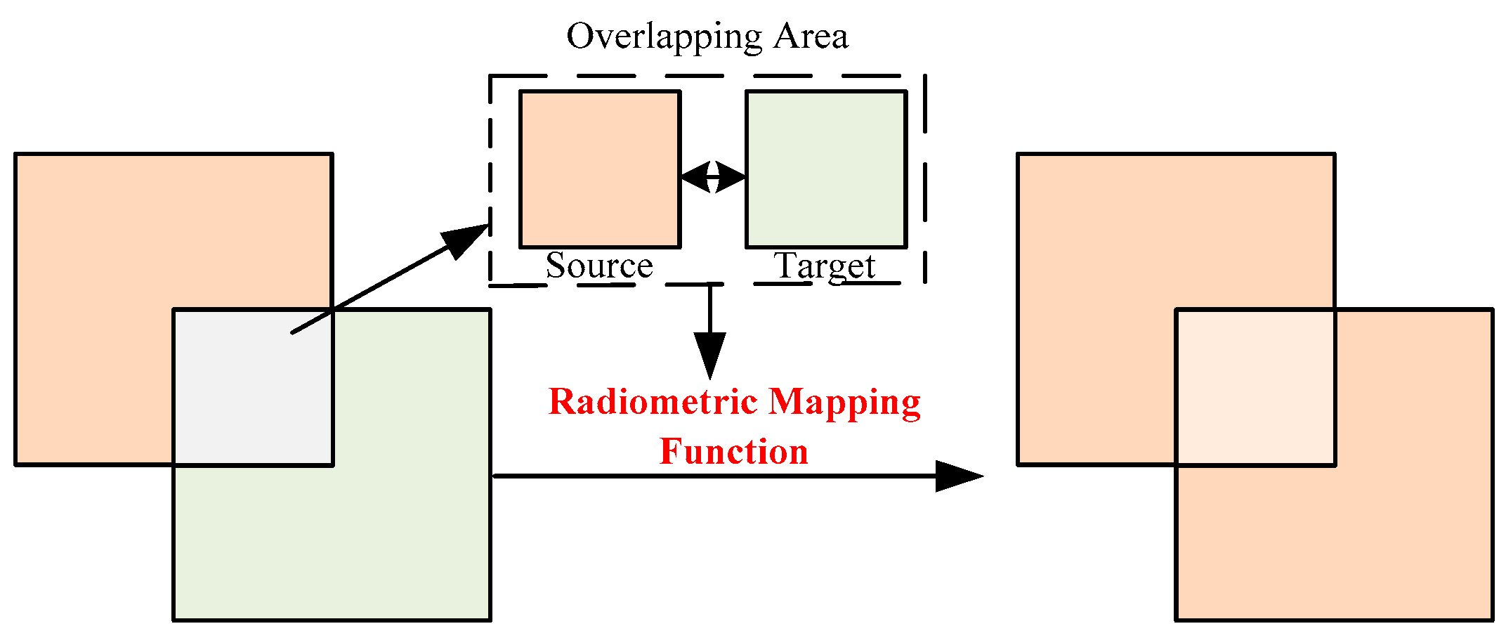
Radiometric normalization operates under the assumption that the reflection conditions in the overlapping regions of two images remain static. As such, pixel pairs from the overlapping areas of two images are used to compute the mapping relationship. This relationship is then extended to the global image, as depicted in
Figure 3. Radiometric normalization has three primary methods: global models, local models, and combined models [
7]. Global models are the most widely adopted method, establishing a linear or nonlinear mapping function based on overlapping pixel pairs. One image serves as a reference (source image), while the other is normalized (target image). The global model is mathematically represented as shown in Formula (4):
where
M1 denotes the target image, with
referring to the normalized image, and
f( ) representing the linear or nonlinear function that governs the global image mapping relationship. The mapping function can be derived in diverse ways, including linear regression [
30] and least-mean-square (LMS)-based transformation [
31].
2.1.4. Seamline Detection
Detecting the optimal seamline is a critical step in creating seamless image mosaics. The ideal seamline is characterized by the closest match in pixel values and texture features in the overlapping areas of the two images. Typically, the seamline of the overlapping area is a curved line (see
Figure 1), and the highest-quality output is achieved by cutting and splicing the images along this line.
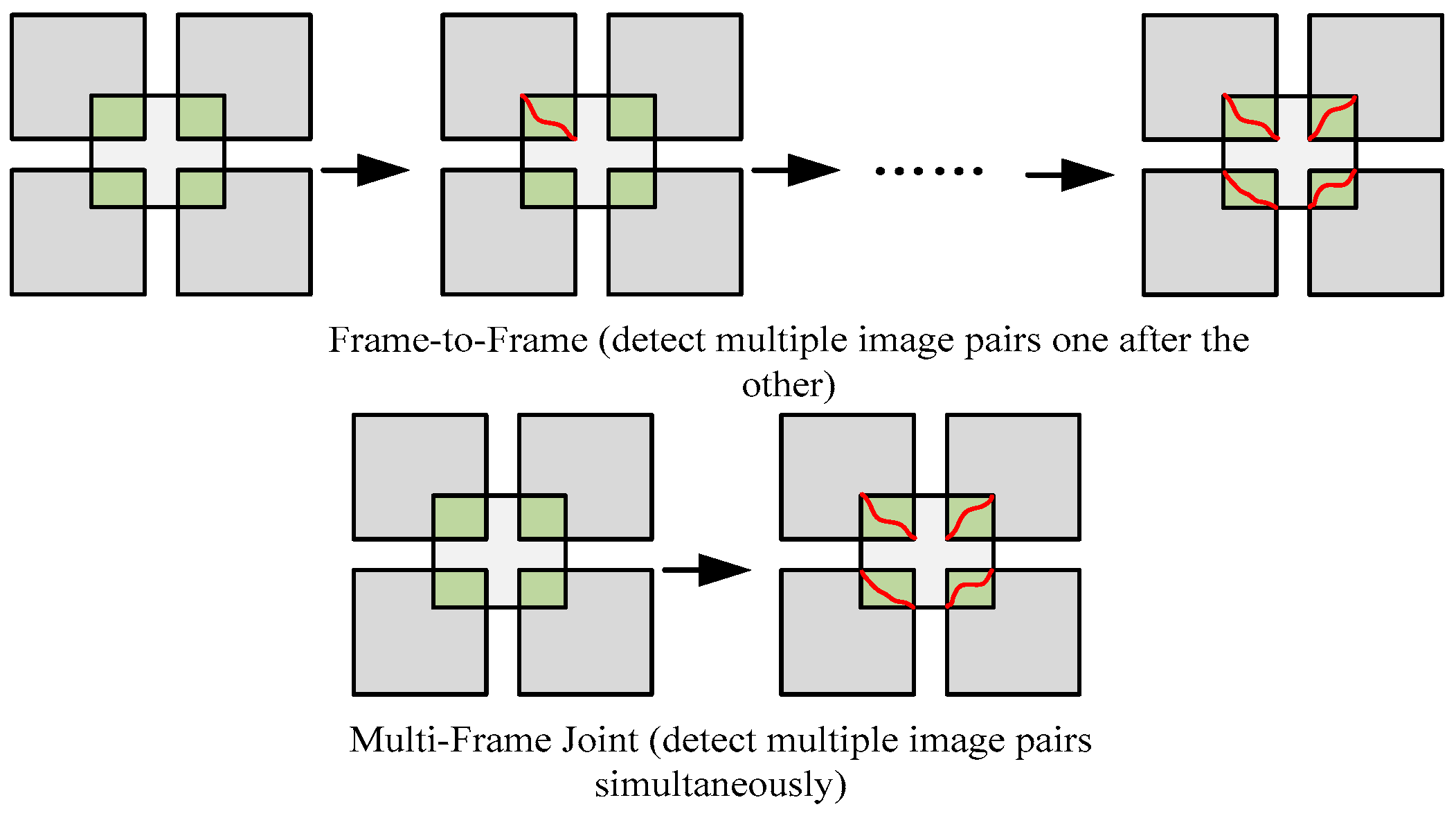
The two primary methods for detecting seamlines are image-internal-information-based and external-data-based [
7]. Since the former is more commonly used, we will focus on this method. The image-internal-information-based method utilizes information within the image, such as pixel values and texture structure, to detect the optimal seamline. This method can be categorized into two detection processes: frame-to-frame and multiframe joint methods (as depicted in
Figure 4). With frame-to-frame detection, seamlines are detected individually, whereas multiframe detection can identify multiple seamlines concurrently. Frame-to-frame detection is more suitable for efficient parallel processing and can be achieved by implementing multiple nodes. The primary frame-to-frame methods include the bottleneck model [
32], the snake model [
33], Dijkstra’s algorithm [
34], and the DP algorithm [
35]. The simplest and most direct method is the bottleneck model, which uses pixel value differences between images to define the cost function, as shown in Formula (5):
where the value of pixel (
i,
j) is
Lij for one image and
Rij for the other, while the cost
Cij is defined as the absolute difference between them. If the overlapping area contains a total of M*N pixels, then any seamline (
SL) is a straightforward path from a row 1 pixel to a row M pixel. Equation (6) represents the cost of any
SL:
The problem of identifying the optimal seamline is equivalent to minimizing C(SL).
2.1.5. Image Blending
Although the optimal seamline displays the path with the least difference, there could be radiometric variation around the seamline. Therefore, image blending is necessary to eradicate inconsistency around the seamline and achieve a seamless transition between the images. As a result of the blending process, a complete mosaic result image is obtained.
The weight combination of transition zones is the most frequently applied blending method [
7]. This combination is realized through a weight function, typically using cosine distance-weighted blending (CDWB) [
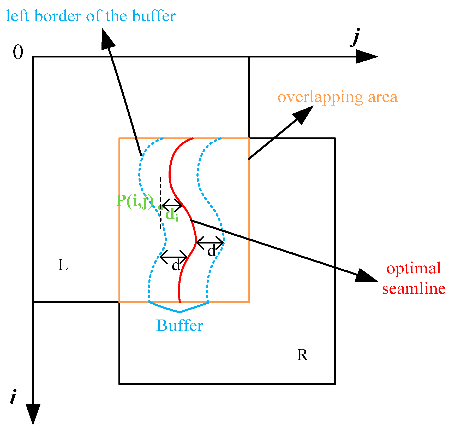
6]. As illustrated in
Figure 5, CDWB creates a buffer along the seamline, known as the transition zone. The pixels within the transition zone result from the weighted combination of the two images, while pixels outside the buffer are obtained from the left and right images on the respective sides of the overlap region. CDWB uses distance as the weight criterion. Thus, pixels closer to the image have a greater weight.
Figure 5 displays that for a pixel P(
i,
j) in the buffer, d is half of the buffer length, while d-di represents the distance from the pixel to the left buffer border. The weight of the left image increases as P(
i,
j) gets closer to the left buffer border, and vice versa for the right image. The expression of the distance ratio
S of P(
i,
j) to the seamline is provided in Formula (7):
where the distance
di from P(
i,
j) to the seamline is negative when P(
i,
j) is on the left side of the seamline, while it is positive when P(
i,
j) is on the right side. The complete mosaicked image,
I, can be obtained using Formula (8):
where
WL(
S) and
WR(
S) are the weights of image
L and image
R in the buffer, respectively. These weights are functions of the distance ratio
S, and they satisfy the conditions that
WL(
S) +
WR(
S) = 1 and 0 <=
WL(
S),
WR(
S) <= 1. This relationship is depicted in Formula (9):
2.2. Overview of the Proposed Algorithm
The core of mosaicking processing is the overlapping area. In fact, overlapping area and non-overlapping area can be processed separately. In this paper, we propose a rapid parallel mosaicking algorithm based on read filtering, as illustrated in
Figure 6. The algorithm consists of three parts: preprocessing, read filtering, and mosaicking processing. In the preprocessing phase, we first extract the overlapping area of the images, divide the images into blocks, and store the blocks in the Hadoop Distributed File System (HDFS). Read filtering is based on the overlapping area and involves reading the intersecting data blocks from the HDFS, filtering out data that fall outside the overlapping area, and reducing the I/O load. Finally, we use Spark to perform parallel mosaicking processing. After the read-filtering process, the overlapping area is read into the distributed memory to form an RDD. For data outside the overlapping area, we load them into memory after the mapping function is obtained from the overlapping area, and then we perform image registration and radiometric normalization. After obtaining the mosaicking results of the overlapping and non-overlapping areas, we combine the two areas to form a whole mosaicking result image.
2.3. Preprocessing
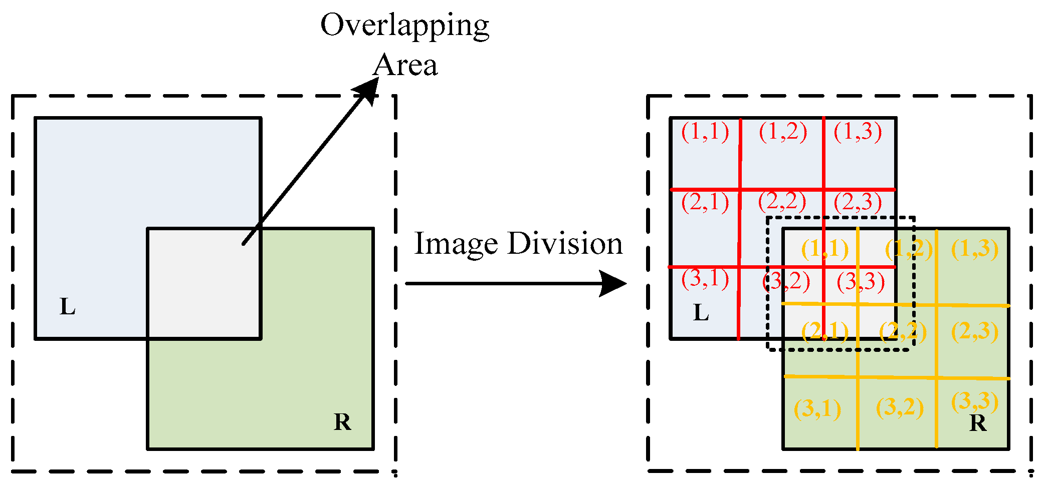
To distinguish between the overlapping and non-overlapping areas in the mosaicking process, we introduce preprocessing. First, we extract the overlapping area, and then we divide the images into blocks, which are stored in the Hadoop Distributed File System (HDFS). The intersecting relationship between the overlapping area and the image blocks forms the basis for read filtering.
To accurately extract the overlapping area, we utilize georeferencing information (if available) and scale-invariant feature transform (SIFT) to extract the union of the overlapping areas. Once the overlapping area is extracted, we divide the images into fixed rectangular blocks and assign a number to each block.
Figure 7 shows that two images, L and R, are partitioned into 9 rectangles, each labeled with a row and column number. The overlapping area intersects with blocks (2,2), (2,3), (3,2), and (3,3) of image L and blocks (1,1), (1,2), (2,1), and (2,2) of image R, which constitutes the mapping relationship between the overlapping area and the image blocks: Map (overlapping area) = {L (2,2), L (2,3), L (3,2), L (3,3), R (1,1), R (1,2), R (2,1), R (2,2)}.
Distributed storage provides underlying data support for parallel processing, and concurrent computing nodes can read data from distributed storage. The open-source big data system, Hadoop Ecosystem, offers a two-tiered framework of distributed storage (HDFS) and parallel processing using MapReduce and Spark. HDFS is a fault-tolerant file system suitable for deployment on commodity hardware with efficient data access. In this paper, we design a storage structure for images using HDFS’s MapFile [
36].
As shown in
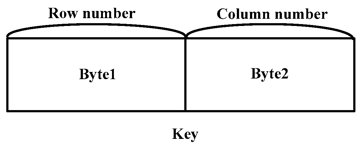
Figure 8, MapFile consists of two key–value files: one for storing data, and the other for storing indices. The data in MapFile are sorted by keys, and an index is generated using the key and the offset of each key value in the data file. Image blocks that are partitioned are stored in the data file of MapFile. Each image block corresponds to a key–value pair, in which the key denotes the image block number, while the value represents the serialized image block stream. For the image block number (key) and the serialized image block stream (value), we store them using two bytes and a byte array, respectively. The key occupies two bytes, and the correspondence between the image block number (i.e., row number and column number) and the key is shown in
Figure 9. The row occupies the first byte, and the column occupies the next byte. With a maximum of 27 rows and columns, there are a total of 27^2 image blocks. The maximum capacity of the block stream is determined by setting the array length.
2.4. Read Filtering
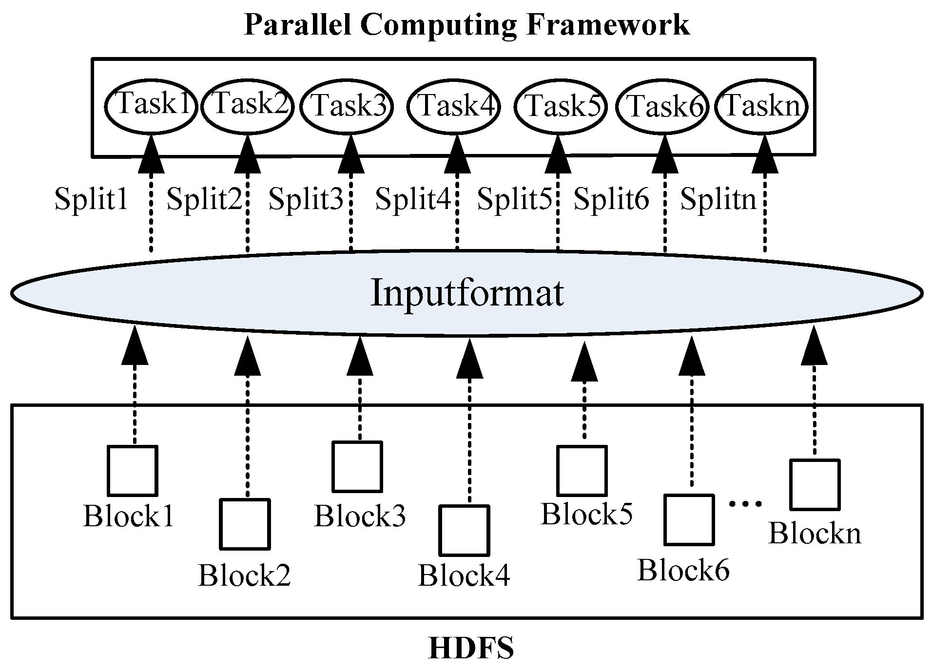
Preprocessing describes the storage of images in the MapFile in blocks, as well as their retrieval based on the mapping relationship with the overlapping area. To achieve asynchronous reading of both overlapping and non-overlapping areas, a special input format of MapFile called read filtering is utilized. MapReduce/Spark applications are divided into multiple subtasks, with each subtask processing a particular input data split that is further subdivided into records. A record corresponds to a key–value pair, and the split data are read in parallel at each task node. The input data split represents a logical concept that corresponds to a physical HDFS data block. In Hadoop, this split is abstracted into the InputSplit class, which contains information such as the split length field in bytes and a method to obtain the data location. The interaction between the computing framework and the HDFS is shown in
Figure 10. It can be seen that InputFormat is the interface for the parallel computing framework to read from the HDFS. Based on InputFormat, the mapping between HDFS data blocks and data splits of the task is established.
Creation and segmentation of the input data split is handled by the abstract class InputFormat and its subclasses. As the parent class of all InputFormats, the abstract class InputFormat consists of two abstract methods:
Public abstract list<InputSplit> getSplits (JobContext context):
This method is utilized to acquire the input split, which is then forwarded to the master node. The master node schedules tasks based on the storage location information and assigns input splits in the closest possible proximity to each task.
Public abstract RecordReader<K,V> createRecordReader (Input Split split, TaskAttemptContext context):
This method creates an iterator object called RecordReader to traverse through the specified input split. The RecordReader is then utilized to divide the input split into records (key–value pairs) that can be processed by the task.
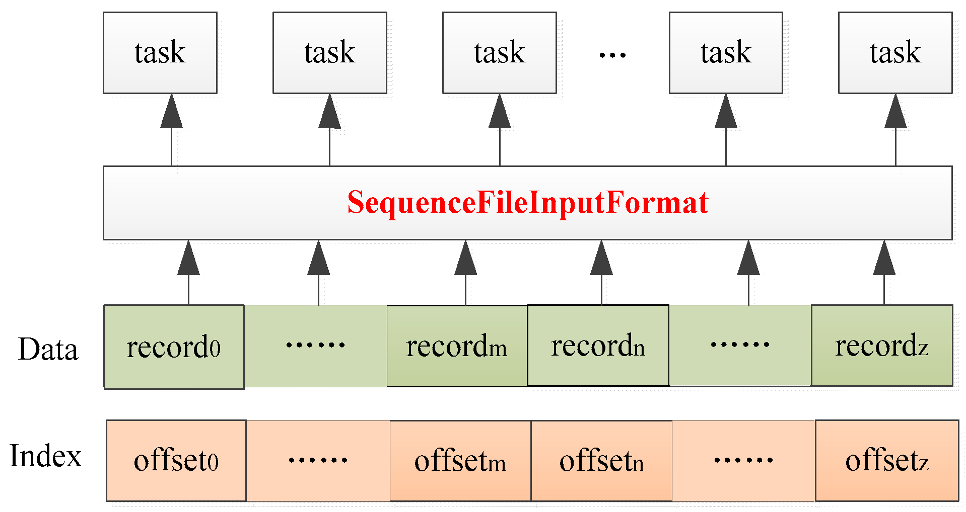
The above statement reveals that InputFormat specifies rules that the parallel computing framework must abide by while reading the HDFS. The native InputFormat for MapFile is SequenceFileInputFormat, which extends FileInputFormat. The SequenceFileInputFormat class provides an implemented createRecordReader method. This method is responsible for creating a data iterator for the input split. The iterator creates a reader instance, identifies the input split’s location within the data, and iterates over records from beginning to end. Each record is then passed on to the task for processing. This approach allows for efficient reading of data in MapFile and easy integration with the parallel computing framework. Reading MapFile based on SequenceFileInputFormat is shown in
Figure 11.
However, when reading the MapFile based on SequenceFileInputFormat, the index is not utilized. Instead, all key–value pairs are read sequentially without regard for their location, which does not meet our specific requirements. Based on the mapping relationship between overlapping areas and image blocks, we can redefine the InputFormat of the MapFile to enable concurrent random reading of image data blocks and on-demand data retrieval. Thus, asynchronous reading of both overlapping and non-overlapping areas is achieved. In this section, we propose and implement MapFileInputFormat: a dedicated parallel InputFormat designed for MapFile. This InputFormat extends SequenceFileInputFormat, rewrites the createRecordReader method, and returns a specific split iterator. Its createRecordReader is as follows:
Public RecordReader<K,V> createRecordReader(Short[] args, InputSplit split, TaskAttemptContext context).
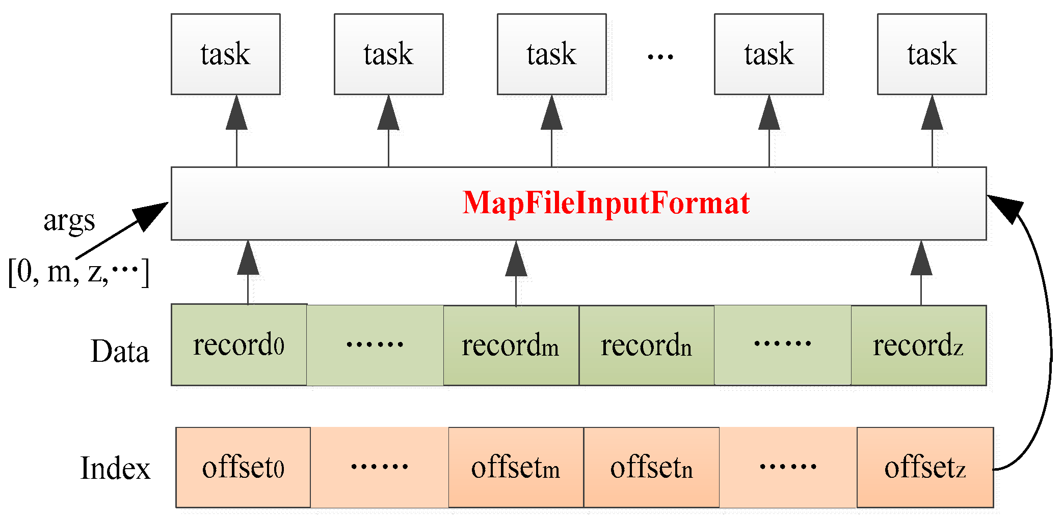
This method creates a MapFile iterator for the input split. For the split iterator, the split is read according to the method parameter args. The key–value records corresponding to the parameter args are read out and passed to the task. The key points of the split iterator are to return to the upper-level directory of the data file, create an instance of MapFile.Reader, load the index file into memory, and randomly read the input split according to the parameter args and index. In fact, when reading the overlapping area data, the method parameter Short[] args is the set of keys of the image blocks that intersect with the overlapping area.
The MapFileInputFormat is more flexible for parallel reading of MapFile. As illustrated in
Figure 12, the MapFileInputFormat can randomly read image blocks according to the specified read parameter and index.
2.5. Mosaicking Processing
In this section, we employ Spark to accomplish parallel mosaicking processing of remote sensing images. Spark was proposed by the AMP Lab of Berkeley University in 2009 [
24]. In summary, Spark is a comprehensive analysis engine for large-scale data processing that operates on clusters and delivers potent parallel computing capabilities. Resilient Distributed Datasets (RDDs) are the foundation of Spark, serving as a representation of distributed memory that is partitioned, read-only, and supports a broad range of operations. Operations on RDDs are categorized into input, transformation, and action.
During preprocessing, the images intended for mosaicking are separated into image blocks and saved in MapFiles. Spark randomly reads the MapFiles in parallel based on the MapFileInputFormat. The mapping relationship between the overlapping area and the image blocks enables asynchronous reading of the overlapping and non-overlapping areas. Firstly, the image blocks that intersect with the overlapping area are read into memory to generate an overlapping area RDD. Then, image registration, radiometric normalization, seamless detection, and image blending are executed. Next, the remaining image blocks are read into memory to form the non-overlapping area RDD, and image registration and radiometric normalization are carried out based on the mapping relationship computed from the overlapping area. Lastly, the overlapping area RDD and non-overlapping area RDD are merged to create the final image. In summary, Algorithm 1 illustrates a rapid parallel mosaicking algorithm for remote sensing images that leverages read filtering.
| Algorithm 1. Rapid parallel mosaicking algorithm Spark-RF |
| Input: Images |
1. OverlappingAreaExtraction(Images) → Array[OverlappingArea]
//Extract overlapping areas (OAs) between images and store them in an array; each OA is represented in either geospatial coordinates or row and column coordinates, depending on whether the image is georeferenced or not. The array functions as a shared Spark variable, allowing computing nodes to access it.
2. Preprocessing(Images) → MapFiles
//Divide the images into blocks and store to the HDFS in MapFiles.
3. For MapFile in MapFiles
3.1. Mapping(Array[OverlappingArea]) → Array[BlockIntersectOAs], Array[BlockOutsideOAs]
//Based on the relationship between each image and the OAs, an array of image blocks intersecting the OAs and an array of image blocks outside the OAs are obtained. Each image block in the array is identified by a block number.
3.2. Spark.ReadMapFile(MapFileInputFormat(Array[BlockIntersectOAs])) → OAPairRDD
//Based on the proposed MapFileInputFormat and block number, the blocks that intersect the OAs are read into memory to form OAPairRDD.
3.3. Spark.ReadMapFile(MapFileInputFormat(Array[BlockOutsideOAs])) → NonOAPairRDD
//Based on the proposed MapFileInputFormat and block number, the blocks outside the OAs are read into memory to form NonOAPairRDD.
4. For eachOAPairRDD
4.1. OAPairRDD.FlatMaptoPair(Array[OverlappingArea]) → FlatPairRDD
//By assessing the intersection between each image block and the OAs, we can determine the OAs that each image block covers. If a single block extends over multiple OAs, it must be assigned to all of those OAs. The block’s key is then associated with the intersecting OA, and a field recording the image block number is added to the value of the block.
5. FlatPairRDD1.cogroup(FlatPairRDD2)…cogroup(FlatPairRDDn) → GroupPairRDD
//Given the preceding step’s transformation, the FlatPairRDD key becomes indicative of the OA. To aggregate image blocks that share the same key, which signifies the same OA, we employ a cogroup operation.
6. GroupPairRDD.MapValues(MosackingProcessing) → MosaickedOAPairRDD
//Currently, the image blocks that intersect with same OA are collected together as one. Based on the block number in the value of the block (step 4.1), the blocks from the same image are combined in memory to form the mosaic area. For each mosaic area, mosaicking processing is performed based on the algorithms discussed in Section 2. It should be noted that the image registration and radiometric normalization mapping functions must be saved to the disk for the processing of image blocks outside the OAs in the next step.
7. NonOAPairRDD.MapValues(ImageRegistration and RadiometricNormalization) → MosaickedNonOAPairRDD
//Based on the registration and normalization mapping functions derived from the previous step, mosaicking of data outside the OAs is performed on the NonOAPairRDD derived from step 3.
8. MosaickedOAPairRDD.CollectAsMap( ) → OAMap
MosaickedNonOAPairRDD.CollectAsMap( ) → NonOAMap
//Return the mosaicking-processed OAPairRDD and NonOAPairRDD to the master node in the form of a map table.
9. Splice(OAMap,NonOAMap) → MosaickedImage
//On the master node, the map tables of OA and NonOA are merged to create the final complete image.
Output: Mosaicked Image |
The flatMapToPair, cogroup, mapValues, and collectAsMap Spark operators are used in the parallel mosaicking algorithm described in Algorithm 1. The first three are transformation operations, while collectAsMap is an action operation. Note that in step 6, the mutual-information-based method is used for image registration, the LMS-based method is used for radiometric normalization, the bottleneck-model-based method is used for seamline detection, and the CDWB algorithm is used for image blending.
4. Discussion
The current parallel mosaicking algorithm mainly uses the characteristics of the parallel computing framework itself to parallelize the mosaicking task. MPI is based on multithreading and distributed file systems, while Spark is based on RDDs. However, remote sensing image mosaicking is not only a data-intensive task but also a computationally intensive task. If we can analyze the characteristics of the mosaicking algorithm and optimize the mosaicking flow on the basis of advanced parallel computing technology, the efficiency of parallel mosaicking will be improved.
In this study, we asynchronously processed the overlapping areas and non-overlapping areas in the mosaicking algorithm based on read filtering, and then we performed full-step mosaicking processing on the overlapping areas, while only performing image registration and radiometric normalization on the non-overlapping areas, which was expected to greatly reduce the cluster data I/O and computing load, thereby accelerating the mosaicking of massive remote sensing images.
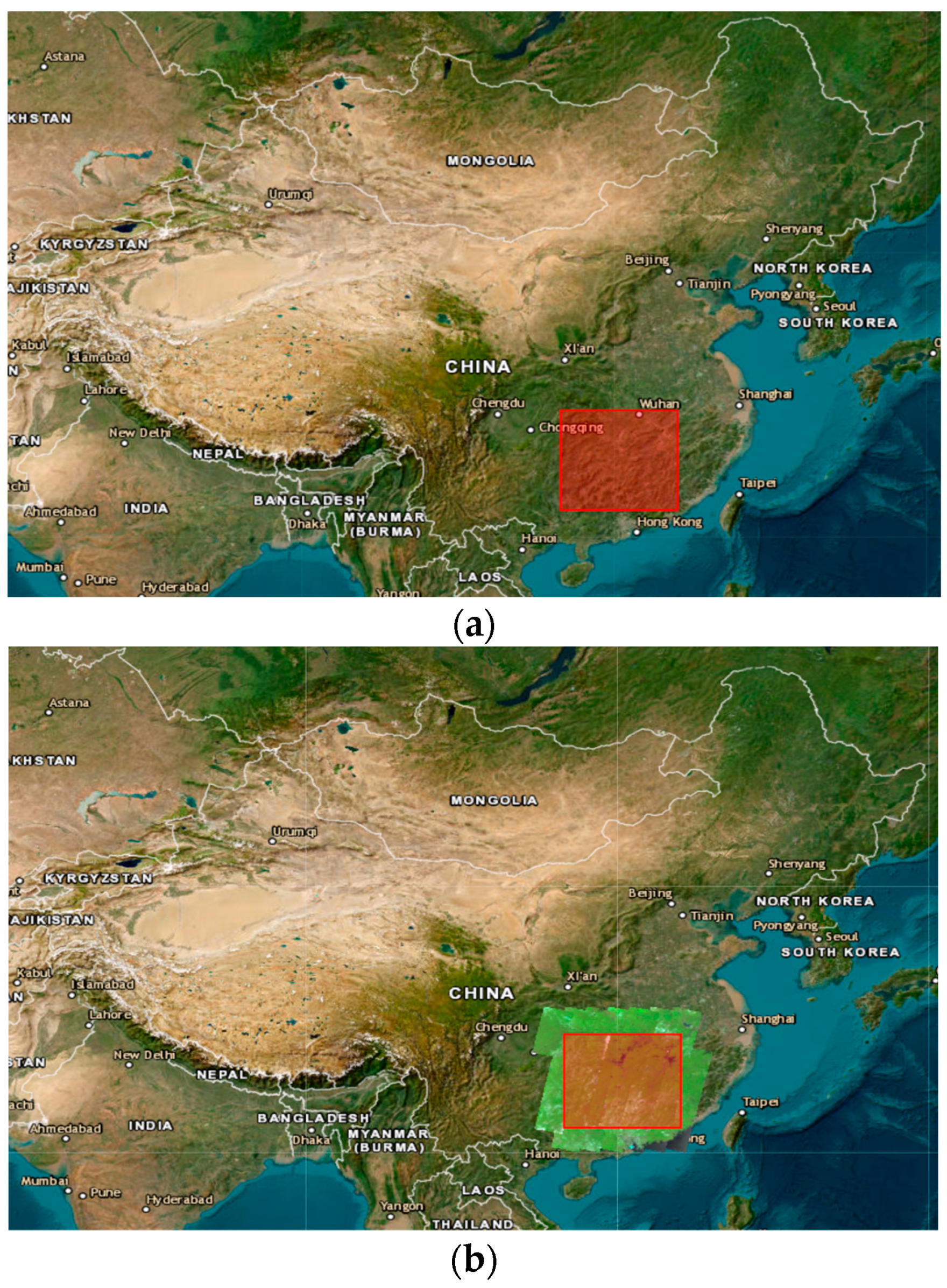
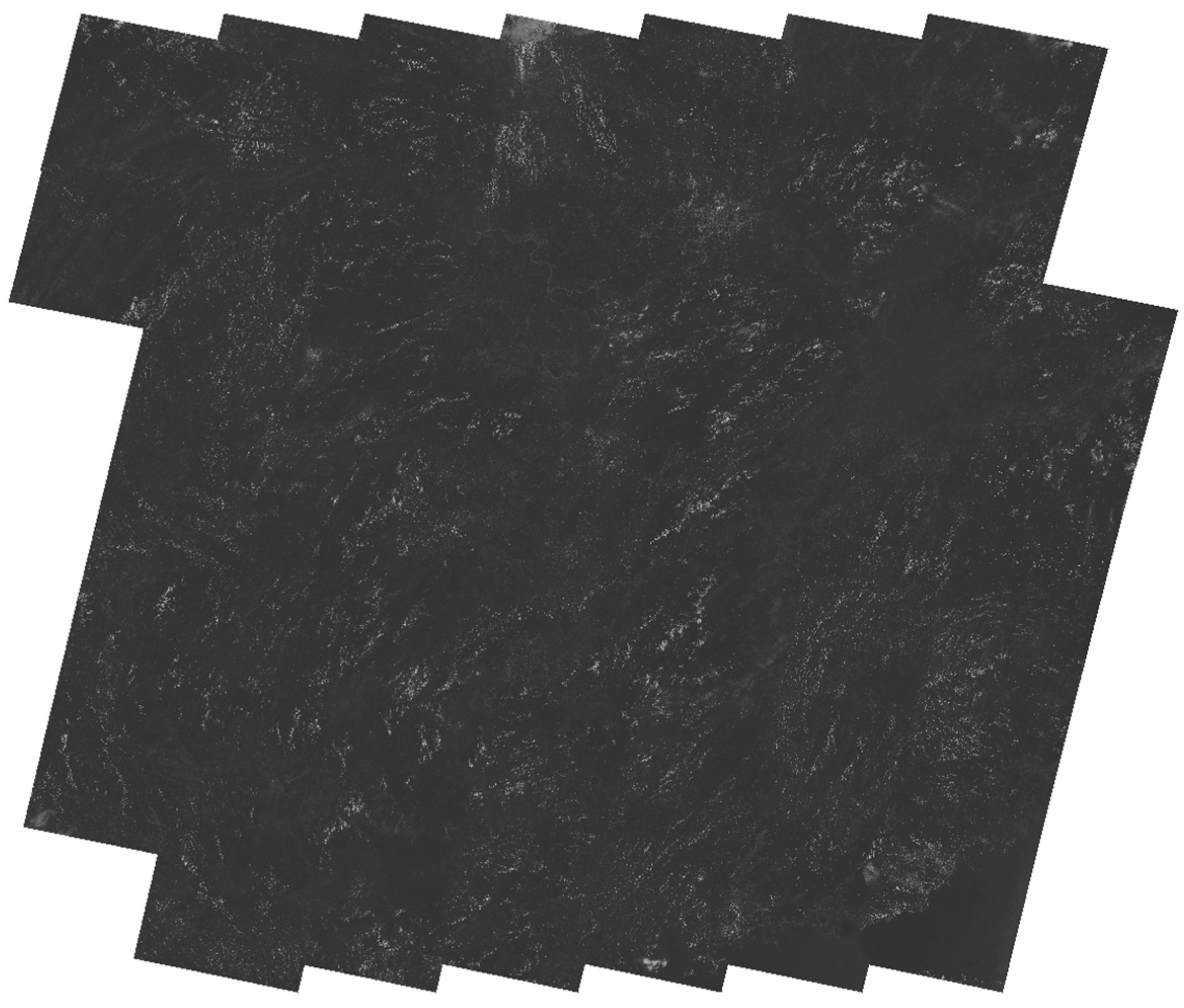
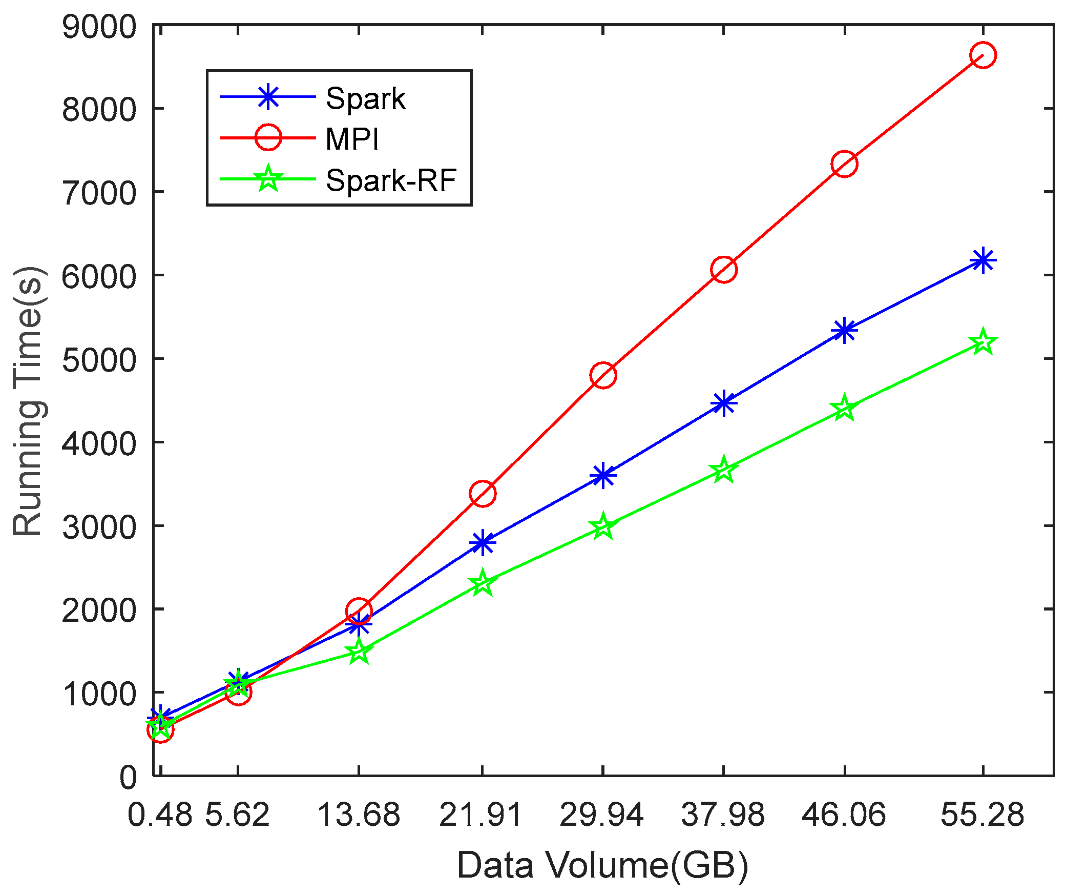
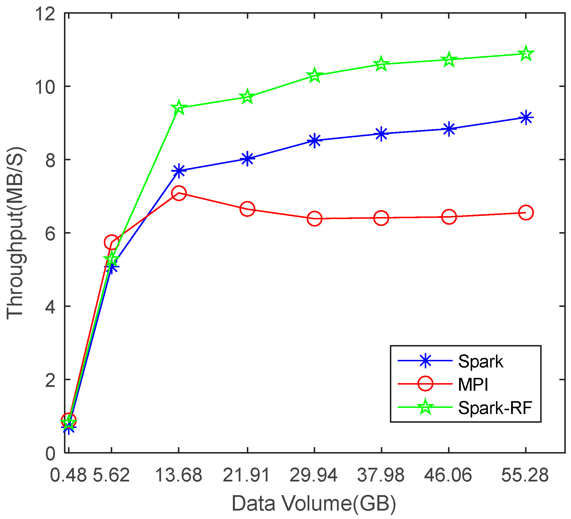
Figure 14 shows that the parallel mosaicking algorithm proposed in this paper is feasible. The results of Experiment 1, as shown in
Figure 15 and
Figure 16 and
Table 2 and
Table 3, show that the Spark-based parallel mosaicking algorithm is more efficient than MPI, and that the mosaicking algorithm proposed in this paper has less running time and higher throughput than state-of-the-art algorithms. The results of Experiment 2 (
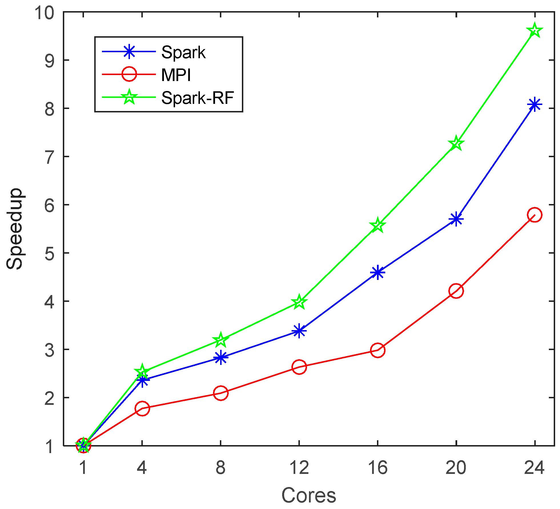
Figure 17 and
Table 4) show that the mosaicking algorithm proposed in this paper has good scalability. In summary, we can say that it is effective to accelerate parallel mosaicking by optimizing the flow of mosaicking.
However, further improvements are still required. First of all, the image data selected in this paper come from the same sensor and are highly consistent, which makes it possible to construct a global polynomial based on mutual information. If the images to be mosaicked come from different sensors or have large differences, other image registration methods will need to be considered. Secondly, looking at the mosaic results in
Figure 14, it can be seen that the transition between images still exists, and better seamline detection and image blending methods are needed in the future. Finally, we can see from
Figure 17 that the speedup of Spark-RF is still far behind the linear speedup, so higher-performance parallel computing technology or further optimization of the mosaicking flow is needed.
