Article

High-Resolution Wideband Waveform Design for Sonar Based on Multi-Parameter Modulation

1
School of Marine Science and Technology, Northwestern Polytechnical University, Xi’an 710072, China
2
Ocean Institute of Northwestern Polytechnical University, Taicang 215400, China
*
Author to whom correspondence should be addressed.
Remote Sens. 2023, 15(18), 4603; https://doi.org/10.3390/rs15184603
Submission received: 25 July 2023 / Revised: 13 September 2023 / Accepted: 17 September 2023 / Published: 19 September 2023

Abstract

:
The design of transmitting waveforms is an effective way to improve the detection performance of sonar systems. For the problem of high-range sidelobe when designing reverberation-resistant waveforms, this paper proposes a high-resolution wideband composite waveform design with reverberation suppression performance and a waveform parameter improvement method. Firstly, we propose a novel wideband waveform, which utilizes linear frequency modulation (LFM) as the fundamental pulse, referred to as multi-parameter coded modulation LFM pulse (MPCM-LFM). Additionally, we deduce the wideband ambiguity function for waveform design. Then, we deduce the constraint relations of the waveform parameters for different sub-band overlaps, and according to the mathematical expressions of the obtained range ambiguity function, we analyze in detail the effects of the waveform parameters on the range ambiguity function under different constraints. Secondly, on the basis of the analysis, we also propose a hopping carrier frequency constraint rule to optimize the spectral performance, and the range sidelobe is restrained effectively in significant measure by this parameter improvement method. Finally, we analyze the computer simulation results. It is obvious that our proposed waveform parameter improvement method leads to good results. The proposed improved MPCM-LFM signal shows a “near-thumbtack” ambiguity function, whose sidelobe suppression performance is superior to other classical waveforms in the desired region, and it can realize high-precision parameter estimation. In addition, the proposed improved MPCM-LFM signal possesses good performance in detecting stationary and low Doppler targets in the background of reverberation.

Graphical Abstract

1. Introduction

The active sonar system transmit waveform not only determines the signal processing method but also directly affects range and velocity resolution, estimation accuracy and interference suppression performance of the system. Therefore, the selection and design of transmit waveform become increasingly important [1]. For many years, the traditional sonar transmits waveforms with fixed parameters, and the research work have mainly been devoted to the optimal processing of the corresponding receivers. However, technological advances have created conditions for the generation and transmission of flexible and variable waveforms, and active sonar waveforms have newly been developed for the design of composite and coded signals in specific environments.
The comb spectrum signal is a class of composite signals. Its energy is distributed in multiple narrowband spectral bands, while the overall performance is a wideband signal. It can be said that it combines the advantages of both narrowband and wideband signals, and is usually used in the shallow sea environment to suppress the low-speed target reverberation interference, such as the sinusoidal frequency (SFM) signal, generalized sinusoidal frequency-modulated (GSFM) signal, and pulse trains of linear frequency modulation (PTFM) signal [2,3,4,5]. However, there are some disadvantages, such as range ambiguous sidelobes, and the improvement of one performance of the signal will reduce the other performance. Coded signals use coded sequences with special properties to modulate the signal parameters and improve the performance while increasing the flexibility of the waveform design, such as time–frequency hopping signals designed with frequency coding [6], phase-coded design based on complementary sequence sets [7], and optimized design combining coding and wideband signals [8,9]. The application of modulation coding can solve the problem of range–Doppler coupling in conventional wideband frequency modulation (FM) signals. The design of the coding sequence can make the signal show a “near-thumbtack” ambiguity function, which has an ideal time–Doppler resolution [10].
Therefore, in order to design time–frequency high-resolution waveforms with reverberation suppression performance, it is necessary to combine the advantages of the above two types of signals, that is, to enhance the reverberation suppression performance of high time–frequency resolution signals or to reduce the high distance blurring sidelobe of signals with reverberation suppression performance. For this reason, in [11], a sonar waveform suitable for moving targets was designed with segmented wideband base pulse composite inter-pulse coded frequency modulation. This modulation significantly enhanced the detection performance of moving targets, but it was only effective in the case of low frequency, and the improvement of the time–frequency resolution ability needs to be further researched. Based on OFD-LFM [12] and Costas [13] pseudo-random sequences, Xu et al. designed discrete frequency coding waveform of orthogonal frequency division linear frequency modulation (DFCW-OFD-LFM) and discrete frequency coding waveform of non-orthogonal frequency division linear frequency modulation (DFCW-NOFD-LFM) for the application of collaborative detection sonar in multiple unmanned underwater vehicles (UUVs) [14]. Simulation results showed that the designed waveforms have a large Doppler tolerance and excellent anti-reverberation capability. However, optimization algorithms are still required to further improve the ability to address the range sidelobe. There were also some methods to solve the problem of high-range sidelobe in the desired region. According to the time–frequency hopping sequence shift [15], modulated signal diversity operation [16] and optimization algorithms are under constraints [17,18] to achieve sidelobe suppression, but the above algorithmic design process requires the establishment of an optimization model that satisfies specific time–frequency conditions or constraints. Consequently, the algorithms become more complicated. Moreover, only numerical examples were given for the wideband FM pulse without theoretical analysis.
In theory, characterizing a given transmit waveform must comprise the derivation of its ambiguity function [19]. It is an effective tool for signal analysis studies and waveform design, which is determined only by the transmit waveform, reflecting the point target response, parameter estimation performance, target discrimination ability, and clutter suppression ability of the system operating in the optimal receive mode [20]. However, when theoretically analyzing the performance of the designed waveform, most of the literature still directly uses the narrowband ambiguity definition for the approximate theoretical derivation of the wideband waveform [21,22,23,24], and does not use the wideband ambiguity function definition for derivation and analysis. An essential way to improve system performance is to analyze and design the wideband waveform that possesses an optimal time–frequency resolution and reverberation suppression capabilities based on the wideband ambiguity function and corresponding signal processing techniques.
In response to the existing issues in the aforementioned research, our motivation is to design waveforms that can reduce range ambiguity sidelobes, possess high time–frequency resolution, and exhibit reverberation suppression capabilities. This will improve the detection and parameter estimation capabilities in complex underwater environments. The main contributions of the research in this paper are listed as follows:
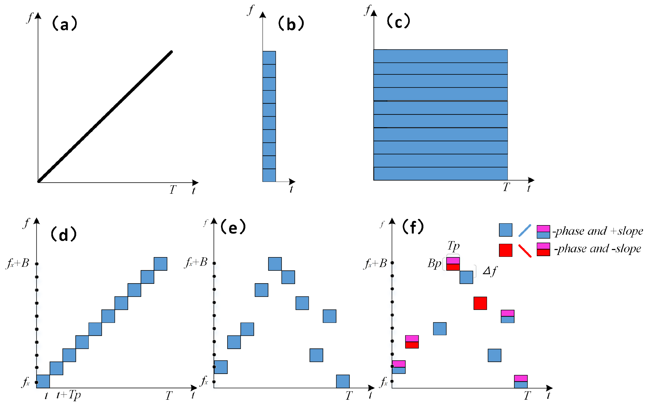
  • We propose a novel high-resolution wideband waveform with reverberation suppression performance called the multi-parameter coded modulation LFM pulse (MPCM-LFM), and deduce its wideband ambiguity function.
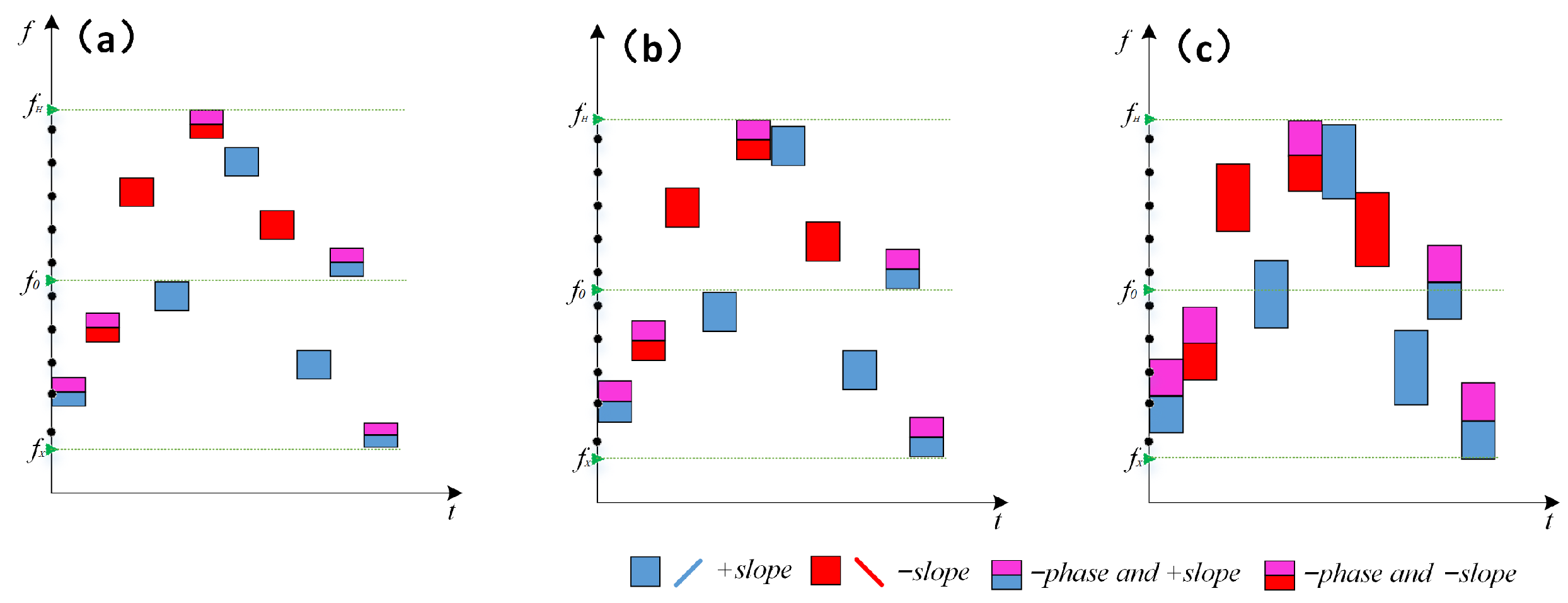
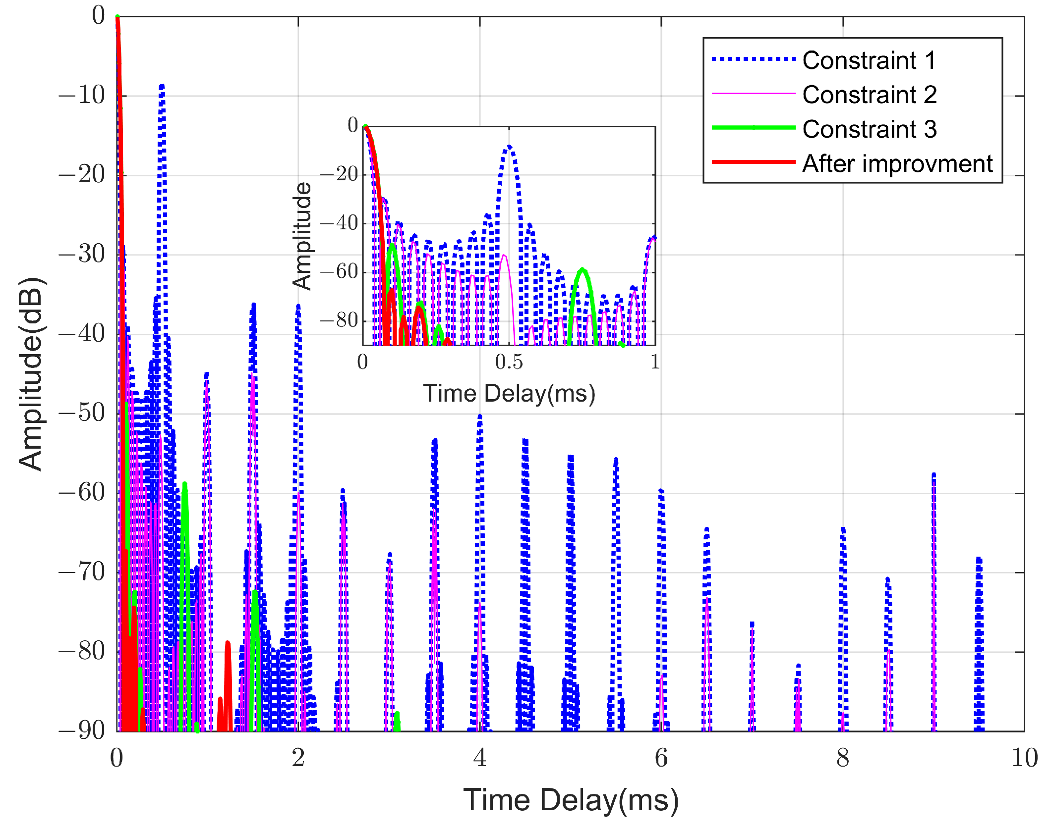
  • We deduce the waveform parameter relations for different sub-band overlaps, and analyze in detail the influence of waveform parameters on the range ambiguity function under different constraints according to the theoretical expression of the range ambiguity function.
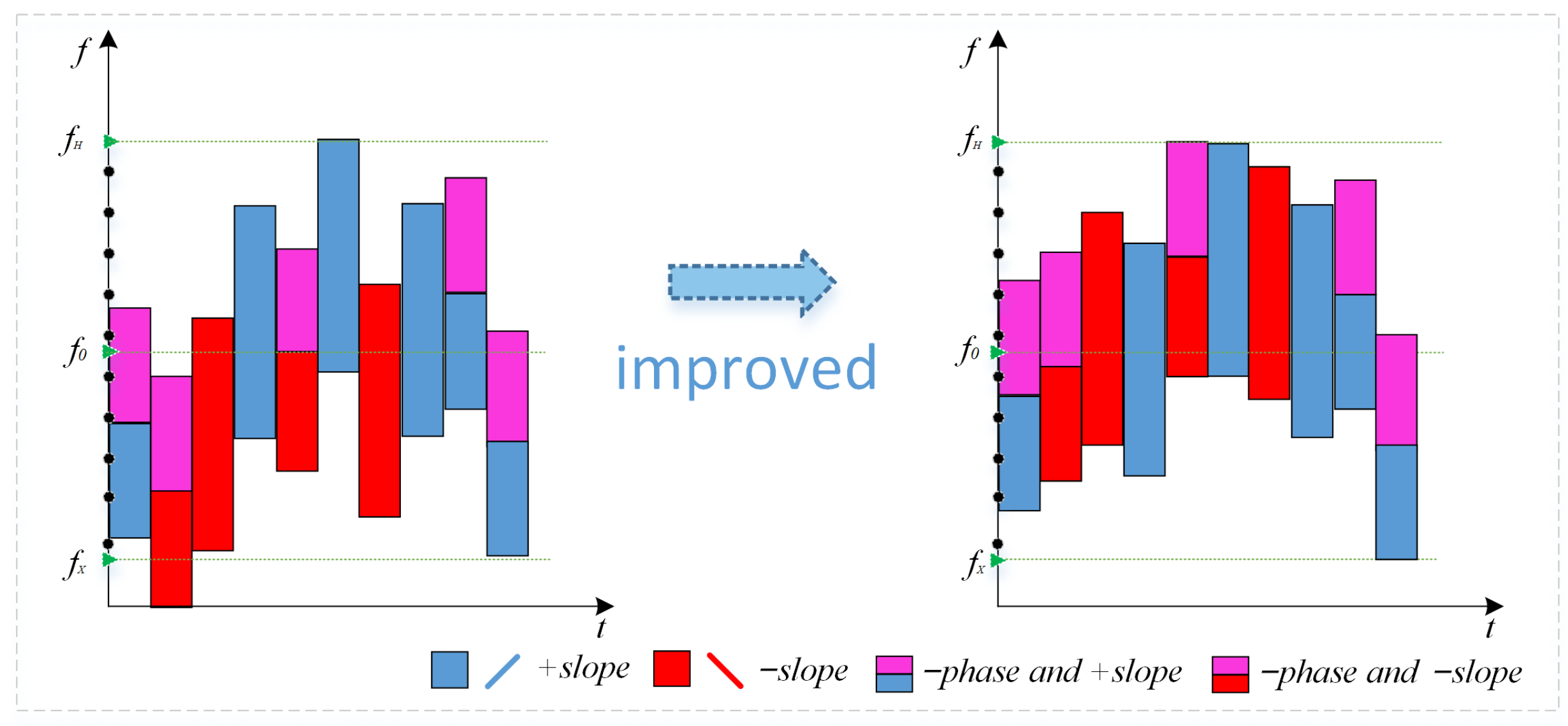
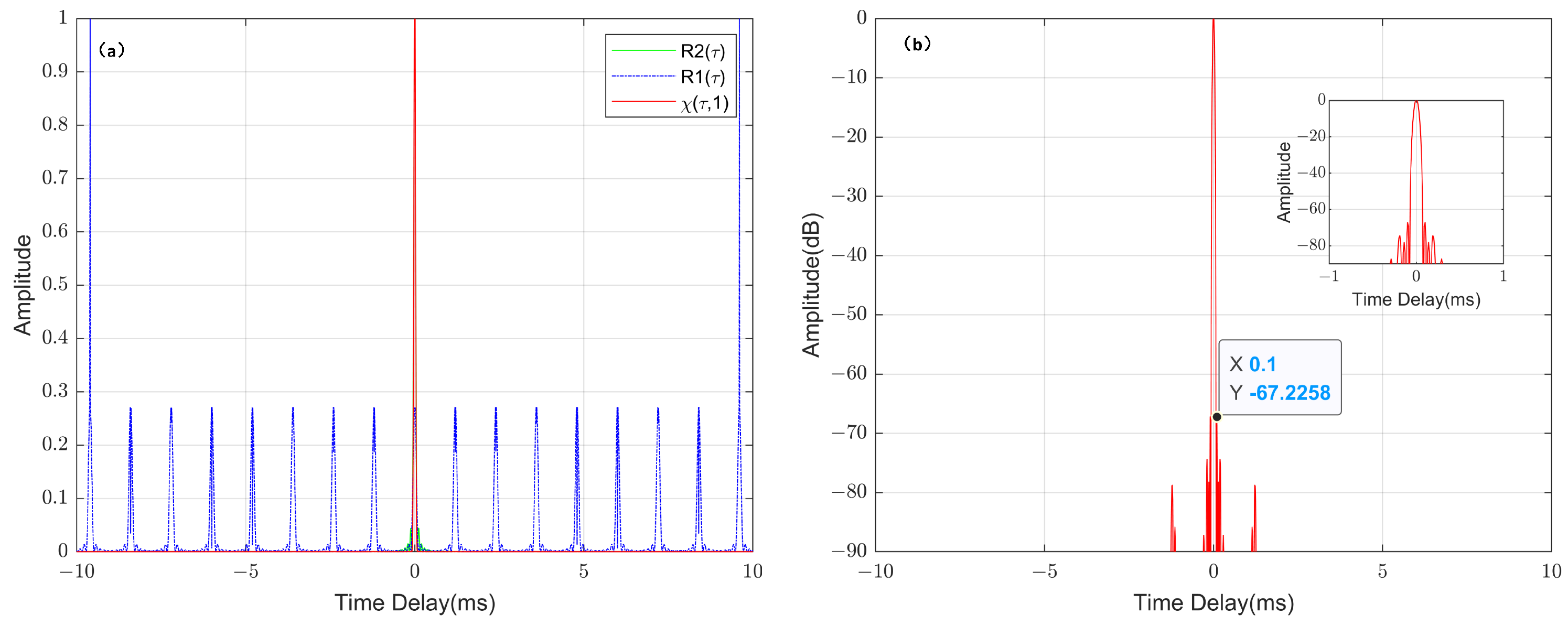
  • On this basis, we also propose a parameter improvement method to realize the suppression of periodic grating while significantly reducing the range ambiguity sidelobe.
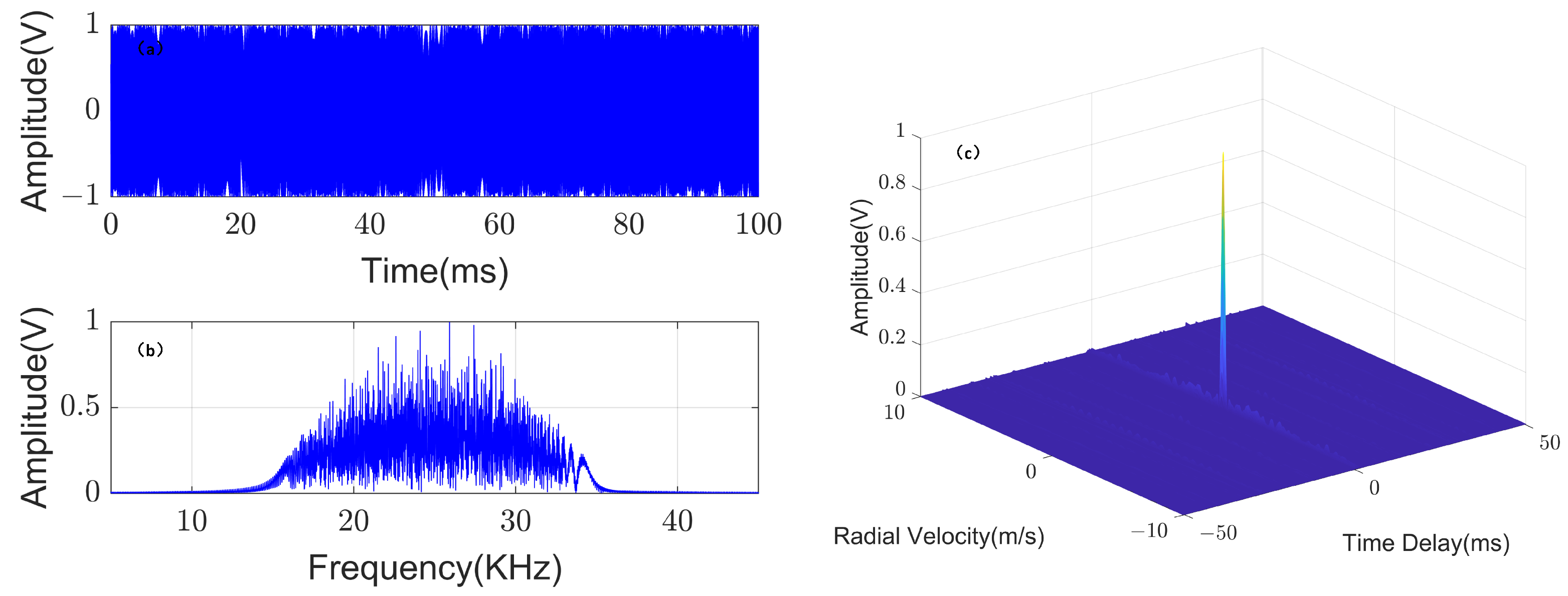
  • The simulation results provide evidence of the correctness of the theoretical analysis and effectiveness of the waveform improvement method. It is shown that the improved MPCM-LFM waveform has good performance in detecting stationary and low Doppler targets in the background of the reverberation, and at the same time possesses the best time–frequency resolution, which can realize high-precision parameter estimation.
The rest of this paper is organized as follows. In Section 2, we propose a wideband waveform design method, establish the MPCM-LFM wideband signal model, and deduce its wideband ambiguity function. In Section 3, we deduce the waveform parameter constraints for different sub-band overlaps, and based on the theoretical analysis, also propose a waveform parameter improvement method. In Section 4, we provide several simulation results. Finally, the conclusions of the paper are given in Section 5.

2. MPCM-LFM Wideband Waveform Design and Deduction of Wideband Ambiguity Function

In this section, we propose a wideband waveform design method and give the mathematical expression of the designed waveform. Then based on the definition of the wideband ambiguity function, we deduce the wideband ambiguity function of the designed waveform.

2.1. MPCM-LFM Wideband Waveform Design

Considering the diversity idea, if the whole wideband signal is divided into several sub-pulses and the parameters, such as the bandwidth and frequency of each pulse, are varied by changing the modulation method or combination method, it is possible to make the sub-pulses have different modulation properties.Then, we can combine the advantages of different waveforms among the pulse signals and design the signal to meet the requirements through the constraints of parameters. Therefore, in this paper, we construct composite wideband waveform based on wideband FM signals and coded signals using time–domain combination, phase modulation, and frequency hopping.
Time–domain combining means dividing the waveform into multiple time segments, and filling the coded or FM signals within each time segment according to a certain pattern, which is expressed as
s t = u 1 t + A · u 2 t t 0 ,
where u 1 t , u 2 t represent a certain coded signal waveform or FM signal waveform, which can be in the same or different forms. t 0 is the combination delay in the range of (0, u 1 t signal pulse width); A is the amplitude combination factor in the range of (0, 1). Since the time–domain combination of bidirectional FM signals can overcome the range–Doppler coupling and obtain better performance than a single signal, when we design the composite wideband signal waveform, we consider the control of the FM exponent (also called the slope) in a certain sequence between the sub-pulses to realize the time–domain combination of positive and negative bidirectional FM signals.
Phase-coded modulation utilizes a pseudo-random sequence to code and modulate the phase of each sub-pulse signal to obtain a composite waveform [25]. Since the ambiguity function of pseudo-random coded signals is mostly “near-thumbtack”, there is no coupling between the range and Doppler, and it has good anti-interference performance, but there is Doppler sensitivity (DS) [26]. In application, a composite signal with both waveform properties can be obtained by combining it with LFM signals, which can achieve a large bandwidth and are Doppler-insensitive (DI) [26].
The time–frequency hopping is realized by time–domain combining of the sub-pulse signals after filling different time periods with randomly coded frequency modulation to obtain the reconstructed signals. Frequency random hopping can break the step nature of the inter-pulse frequency shift and obtain the ambiguity characteristic to meet the requirements through the change of the hopping rule [27]. Combining the above analysis, through certain coding modulation rules, the modulation frequency, slope and phase of the wideband base pulse are combined and modulated to obtain a balanced and optimized waveform in all aspects of performance. The schematic diagram of the waveform design is shown in Figure 1.
According to the schematic in Figure 1, we use LFM signal as the base pulse, modulate the waveform parameters using multiple coding sequences, and combine the DS and DI waveform characteristics to make the signal simultaneously Doppler sensitive (for detecting moving targets) and with high time–frequency resolution. In this method, we can control the carrier frequency, slope and phase of the sub–pulse signals based on coded sequence combinations, and we can also independently change the modulating carrier frequency and bandwidth of each sub-pulse signal to construct sub-pulse combinations with different band overlap so as to obtain different performance of the waveforms. The proposed waveforms are called multi-parameter coded modulation LFM pulse (MPCM-LFM). According to this idea, the above theory is mathematically described. The mathematical expression of the designed MPCM-LFM signal and its modulated sub-pulse are as follows:
x ( t ) = 1 T n = 0 N 1 x n ( t n · T p )
x n ( t ) = L n x A n t · e j 2 π f n t ,   0 t T p
Here, x A n t is the complex envelope (i.e., sub-pulse signal waveform) of the signal x n t , denoted as
x A n ( t ) = r e c t ( t T p ) e j 2 π f 0 t + 1 2 K n t 2 ,
r e c t ( t T p ) = 1 ,   0 t T p 0 ,   t < 0 , t > T p ,
where N indicates the number of sub-pulses. f n is the carrier frequency of the sub-pulse, which is modulated by the frequency coding sequence of C n and belongs to the set f 0 B / 2 ,   f 0 B / 2 + C n 1 · Δ f , ,   f 0 B / 2 + N 1 · Δ f . f 0 is the center frequency of the wideband composite waveform. Δ f = m m T p T p indicates the frequency-hopping interval of sub-pulses, where m is a natural number and T p is the width of sub-pulses. B p is the bandwidth of sub-pulses, and K n = G n · B p B p T p T p indicates the modulation slope of sub-pulses. G n indicates the coding sequence for the FM slope, and the code elements are expressed by 1 and 0, where 1 is positive FM and 0 is negative FM. L n represents the phase-coding sequence; there are pseudo-random sequences, such as Barker code, M sequence, etc., which are used to modulate the phase of each sub-pulse, taking +1 or −1 (some code elements are represented by 1 and 0; in this case, 1 means +1, while 0 means −1).
The performance in the time–frequency domain of the signal further illustrates the waveform design method. Starting from the standard OFDM signal model, Figure 2a shows the LFM signal for a given bandwidth B and the time width of the pulse T which is taken as the base pulse. Figure 2b shows the standard OFDM signal model, which consists of N sub-pulses in the frequency domain [28], separated by the frequency hopping interval Δ f . According to the constraints of bandwidth and time width, the OFDM signal in the time–frequency domain is obtained as shown in Figure 2c, that is, the same sub-pulse signals are sent at the same time, which occupies the whole pulse width time and will require a large sampling rate to be sampled when receiving the signal. In order to carry out the sub-pulse parameter setting flexibly and reduce the sub-pulse time width, the carrier frequency of each sub-pulse is converted to a step-increasing frequency with a frequency-hopping interval Δ f as shown in Figure 2d, and the time domain combination is utilized to obtain the complete system bandwidth. A random frequency coding sequence is added to improve the waveform characteristic and obtain the performance in the time–frequency domain as shown in Figure 2e, i.e., to break the step nature of the inter-pulse frequency shift and realize the time–frequency hopping to obtain high-distance resolution. Increasing the random frequency coding sequence improves the waveform characteristic to obtain the performance in the time–frequency domain as shown in Figure 2e, i.e., to break the step nature of the inter-pulse frequency shift and realize the time–frequency hopping to obtain high range resolution. Finally, we combine the slope and phase-coded modulation, add the DS characteristic to improve the detection performance of moving targets in the background of reverberation, and obtain the performance of the designed MPCM-LFM waveform in the time–frequency domain as shown in Figure 2f, with the colors representing the different sub-pulse modulation properties.

2.2. Deduction of Wideband Ambiguity Function for the MPCM-LFM Waveform

In this subsection, we deduce the wideband ambiguity function of the designed waveform. In order to further analyze the sidelobe suppression performance of the waveform, we deduce the wideband range ambiguity function in detail and give an explicit mathematical expression, which lays a theoretical foundation for the subsequent improvement of the waveform.

2.2.1. Deduction of Wideband Ambiguity Function

The wideband ambiguity function of the signal is defined as (positive type expression) [29]
χ ( τ , s ) = s + x ( s t ) x * t + τ d t ,
so
Ψ ( τ , s ) = χ ( τ , s ) 2 ,
where τ is the target echo time delay. s = ( c v ) ( c v ) ( c + v ) ( c + v ) is called the time scale or Doppler compression factor. Here, c is the propagation velocity of the signal in the water and v is the radial velocity of the target, which is negative when moving in the opposite direction. When s = 1 , we obtain Ψ ( 1 , τ ) , called the range ambiguity function, and when τ = 0 , we obtain Ψ ( s , 0 ) , which is called the velocity ambiguity function.
Instead of x ( t ) , we substitute the mathematical expression of the MPCM-LFM signal into the wideband ambiguity function definition Equation (6) to obtain its wideband ambiguity:
Ψ τ , s = χ τ , s 2 = 1 T 2 s . + n = 0 N 1 x n s ( t n T p ) · m = 0 N 1 x m * ( t m T p + τ ) d t 2 = 1 T 2 n = 0 N 1 W n , n ( τ , s ) + m = 0 m n N 1 W n , m ( τ + ( n m ) T p , s ) 2 ,   τ + ( n m ) T p T ,
where W n , n and W n , m are the wideband self-ambiguity function and mutual ambiguity function of the sub-pulse signal, respectively.
It can be seen that the main peak is related to the sum of W n , n , while the sidelobe response is mainly related to the sum of W n , m . Consider that the wideband ambiguity function expression is a more complex form of dual integration, and that the MPCM-LFM signal belongs to the composite modulated signals with frequency diversity and time–domain combination characteristic. Since there are various types of such signals, we would like to deduce a quantitative expression for the wideband ambiguity function with universal applicability, which facilitates the further analysis of the time–frequency resolution of the signal.
Next, we deduce the wideband self-ambiguity function and mutual ambiguity function for each sub-pulse in Equation (8) separately. The n-th sub-pulse of the signal is written according to Equation (3):
x n ( t ) = L n x A n t · e j 2 π f n t = L n r e c t ( t T p ) b n t · e j 2 π f n t ,   0 t T p
In order to facilitate analysis and calculation, it is considered to use the signal complex envelope instead of the signal for solution of the wideband ambiguity function. If it is written as a time–frequency two-dimensional correlation function similar to the narrowband definition, it needs to have a frequency-shift variable φ . However in the wideband case, there are different frequency shifts for different frequencies within the signal bandwidth, so when using the signal complex envelope representation, we need to first deduce the corresponding wideband two-dimensional correlation function form. Based on this, the wideband self-ambiguity function of the sub-pulse is further written as
W n , n ( τ , s ) = s + x n s t x n * t + τ d t = s L n b n ( s t ) e j 2 π f n ( s t ) · L n b n * ( t + τ ) e j 2 π f n ( t + τ ) d t = s · e j 2 π f n τ L n 2 · + b n ( s t ) b n * ( t + τ ) e j 2 π s f n f n t d t = L n 2 · e j 2 π f n τ s + b n ( s t ) b n * ( t + τ ) e j 2 π φ t d t = L n 2 e j 2 π f n τ · χ b n , n τ , s , φ ,
where φ = β f n = s 1 f n is the Doppler shift of the sub-pulse signal with respect to its center frequency, corresponding to the wideband frequency shift autocorrelation function of the sub-pulse complex envelope expressed as
χ b n , n ( τ , s , φ ) = s + b n ( s t ) b n * ( t + τ ) e j 2 π φ t d t
Similarly, the wideband frequency shift cross-correlation function of the complex envelope between sub-pulses is
χ b n , m ( τ , s , φ ) = s + b n ( s t ) b m * ( t + τ ) e j 2 π φ t d t
Accordingly, the process of deriving the wideband mutual ambiguity function of sub-pulse is as follows:
W n , m ( τ , s ) = s + x n s t x m * t + τ d t = s L n b n ( s t ) e j 2 π f n ( s t ) · L m b m * ( t + τ ) e j 2 π f m ( t + τ ) d t = L n L m e j 2 π f m τ · s + b n ( s t ) b m * ( t + τ ) e j 2 π s f n f m f n + f n t d t = L n L m e j 2 π f m τ · s + b n ( s t ) b m * ( t + τ ) e j 2 π φ + f n f m t d t = L n L m e j 2 π f m τ · χ b n , m τ , s , φ + f n f m
Substituting Equations (10) and (13) into Equation (8) yields the wideband ambiguity function of the MPCM-LFM signal
Ψ τ , s = χ τ , s 2 = 1 T 2 n = 0 N 1 W n , n ( τ , s ) + m = 0 m n N 1 W n , m ( τ + ( n m ) T p , s ) 2 = 1 T 2 n = 0 N 1 L n 2 e j 2 π f n τ · χ b n , n τ , s , φ + m = 0 m n N 1 L n L m e j 2 π f m ( τ + ( n m ) T p ) · χ b n , m τ + ( n m ) T p , s , φ + f n f m 2
From Equation (14), as long as the explicit expression of the signal is given and the ambiguity function χ b n , n τ , s , φ of the sub-pulse waveform’s complex envelope is calculated accordingly, we can obtain the wideband ambiguity function of the composite waveform. It means that the composite modulation signal that satisfies the characteristic of the time–domain combination and frequency diversity, its wideband ambiguity function can be expressed by the ambiguity function of the sub-pulse waveform’s complex envelope.

2.2.2. Deduction of Wideband Range Ambiguity Function

For the purpose of following up the theoretical analysis of the influence of MPCM-LFM signal waveform parameters on the sidelobe suppression performance and realizing the waveform improvement, this subsection deduces the range ambiguity function of the signal in detail and gives an explicit mathematical expression.
First, we substitute s = 1 into Equation (14) to obtain the range ambiguity of the signal
Ψ τ , 1 = χ τ , 1 2 = 1 T 2 n = 0 N 1 L n 2 e j 2 π f n τ · χ b n , n τ , 1 , 0 + m = 0 m n N 1 L n L m e j 2 π f m ( τ + ( n m ) T p ) · χ b n , m τ + ( n m ) T p , 1 , f n f m 2
Theoretically, we utilized the time–domain combination method in designing the MPCM-LFM signal, where different sub-pulses occupy different time periods from each other. When calculating the integrals, there is no intersection between the autocorrelation intervals of the two sub-pulses, so according to Equation (12), we obtain
χ b n , m ( τ , 1 , φ ) = + b n ( t ) b m * ( t + τ ) e j 2 π φ t d t = 0
So, Equation (15) is left with only one term before the plus sign.
The complex envelope of the sub-pulse after removal of carrier frequency can be expressed as
b n ( t ) = L n r e c t ( t T p ) e j π K n t 2 ,
Substituting into Equation (11) and s = 1 , φ = 0 , further deduction results in the following:
χ b n , n ( τ ,   1 ,   0 ) = + b n ( t ) b n * ( t + τ ) d t = + e j π K n t 2 e j π K n t + τ 2 d t = e j π K n τ 2 + e j 2 π φ K n τ t d t = 0 < τ < T p ,   e j π K n τ 2 1 j 2 π φ K n τ e j 2 π φ K n τ t τ T p T p < τ < 0 ,   e j π K n τ 2 1 j 2 π φ K n τ e j 2 π φ K n τ t 0 T p + τ = T p τ . e j π K n τ 2 e j π K n τ T p + τ sin π K n τ T p τ π K n τ T p τ ,   τ < T p ,
so there is
χ τ , 1 = 1 T n = 0 N 1 q n 2 e j 2 π f n τ · χ b n , n τ , 1 , 0 = 1 T n = 0 N 1 e j 2 π f n τ · T p τ . e j π K n τ 2 e j π K n τ T p + τ sin π K n τ T p τ π K n τ T p τ ,
take a mold
χ τ , 1 = 1 T n = 0 N 1 e j 2 π f n τ · T p τ sin π K n τ T p τ π K n τ T p τ = 1 T e j 2 π f 0 B / 2 + B p / 2 τ · n = 0 N 1 e j 2 π n · Δ f τ · T p τ sin π K n τ T p τ π K n τ T p τ = 1 T e j π N Δ f τ sin π N Δ f τ e j π Δ f τ sin π Δ f τ · T p τ sin π K n τ T p τ π K n τ T p τ = 1 T sin π N Δ f τ sin π Δ f τ · T p τ sin π K n τ T p τ π K n τ T p τ = R 1 τ R 2 τ
This suggests that the range ambiguity function of the MPCM-LFM signal consists of two parts, R 1 t and R 2 t . R 1 t is sin π N Δ f τ sin π Δ f τ in Equation (20), i.e., the grating that appears periodically in the signal. R 2 t is χ b n , n τ , 1 , 0 in Equation (20), i.e., the wideband frequency-shifted two-dimensional autocorrelation function of the sub-pulse waveform’s complex envelope.
According to Equation (20), the number of pulses N, the inter-pulse frequency interval and the modulation slope affect the overall performance of the ambiguity function. On the basis of the equation for R 1 t , periodic gratings exist when the frequency increases in linear steps with Δ f , and when the frequency varies non-linearly and randomly, the periodicity of the gratings is destroyed, thus suppressing the gratings. In addition, multiplication with R 2 t , which is shaped like a Sinc function, also suppresses the gate flaps, but there will be a high-range sidelobe, which affects the range resolution. By designing the appropriate signal parameters, we can realize the inhibition of grating and reduce the range ambiguity sidelobe at the same time. When N is certain, the combination of waveform parameters Δ f and K n affects the performance of the sidelobe suppression accordingly. Combined with the performance of MPCM-LFM in the time–frequency domain, when the sub-pulse bandwidth changes, the mathematical relationship between the corresponding waveform parameters m and N can characterize different overlapping degrees of the waveform bands, which can also reflect the variation of combination parameters of Δ f and K n under the constraint of different sub-pulse bandwidths. Therefore, in the next section, we deduce the waveform parameter constraint relations for different frequency band performance results and theoretically analyze the respective range sidelobe suppression performance in conjunction with Equation (20). On this basis, we propose an improvement method for the waveform parameters.

3. Performance Analysis of MPCM-LFM Signal under Different Constraints and Waveform Parameter Improvement

In this section, we deduce the constraint relations of waveform parameters for different overlaps of sub-bands based on the mathematical expressions of the MPCM-LFM waveform, and analyze in detail the effects of waveform parameters corresponding to different degrees of frequency band overlap on the range ambiguity function. In light of the analysis results, we propose an improvement approach for the waveform parameters and analyze the changes of the improved parameters on the sidelobe suppression performance. Finally, the wideband waveform parameters that meet requirements and have the best performance are obtained.

3.1. Deduction of Waveform Parameter Constraint Relationships and Analysis of Range Sidelobe Suppression Characteristic

When the sub-pulse bandwidth changes, the frequency band assignments exhibit different degrees of overlap. Accordingly, we categorize the MPCM-LFM waveform into three kinds—one with separate sub-bands without overlap, one with low overlap of sub-bands and the last one with high overlap of sub-bands—which are shown in Figure 3a–c, respectively. The corresponding mathematical relationships between the waveform parameters m and N under the constraints of different sub-pulse bandwidths can characterize the different overlapping degrees of the waveform frequency bands, so we deduce the corresponding constraints relationships between m and N.
Following the design rules of the waveform in Section 2, upper and lower frequency limits of the generated MPCM-LFM wideband composite signal are denoted as
f H = f 0 B / 2 + B p + N 1 Δ f
f X = f 0 B / 2
Under the constraint of the total signal bandwidth, there exists relation
f H f X = B p + N 1 Δ f = B
The mathematical relationships of the corresponding waveform parameters and their performance in the time–frequency domain are discussed in separate cases for different sub-pulse bandwidth constraints.
[Case 1] When B p Δ f is substituted into Equation (23), there is inequality
B Δ f + N 1 Δ f ,
and we simplify to obtain
Δ f B N ,
and Δ f = m / T p obtains
m B N · T p
Under this constraint, when 0 < B p Δ f 2 , each sub-pulse band is completely separate without overlapping; when Δ f 2 < B p Δ f is the sub-pulse with low band overlapping rate, the corresponding sub-pulse carrier frequency satisfies
f n = f 0 B / 2 + C n 1 · Δ f
[Case 2] When B p > Δ f , the sub-pulse bandwidth satisfies
B p B f X N 1 Δ f ,
corresponding to sub-pulses with high band overlap. The subsequent deduction process is similar to the above, substituting Equation (28) into Equation (23) and associating with Δ f = m / T p . We can solve for
m 2 B f X T p 2 N 2
The sub-pulse carrier frequency at this point satisfies
f n = f 0 B / 2 + B p / 2 + C n 1 · Δ f
In summary, we organize the deduced mathematical relationship between m and N under the sub-pulse bandwidth constraint, as well as the corresponding carrier frequency and different overlap of sub-bands results in Table 1.
For the designed signals under different parameter constraint relations of the three band overlap rates, the sub-pulse bandwidths B p and the deduced m and N relational equations as well as the carrier frequency expressions, corresponding to parameter variations of the combinations of Δ f and K n in Equation (20), accordingly affect the sidelobe suppression performance. To visually analyze the range ambiguity sidelobe suppression characteristics of MPCM-LFM signals under different constraint conditions, we set the signal’s pulse width as T = 100 ms , system bandwidth as B = 20 KHz , and the number of sub-pulses as N = 10 . Based on the mathematical expression for waveform design in Section 2.1 and the parameter constraint relationships derived in Table 1, we calculate the combined parameter values of frequency hop interval Δ f and sub-pulse modulation frequency K n for three different sub-band overlaps of MPCM-LFM signals. Then, these values are substituted into the theoretical Equation (20), yielding the wideband range ambiguity function results for MPCM-LFM signals under different constraints as shown in Figure 4, Figure 5 and Figure 6. The blue dashed line in each figure (a) corresponds to the grating R 1 t , the green solid line is the wideband frequency-shifted autocorrelation function of the sub-pulse waveform’s complex envelope R 2 t , and the red color is the range correlation function of the MPCM-LFM wideband waveform χ τ , 1 . The dB representation of the range correlation function of the wideband waveform is shown in the (b) plot of Figure 4, Figure 5 and Figure 6.
Analyzing Figure 4, Figure 5 and Figure 6, the results demonstrate that the performance of range ambiguity sidelobe suppression is significantly improved as the waveform sub-bands rise, corresponding to the increase in sub-bands overlap. In terms of Figure 6a, the range ambiguity function is getting closer to the form of the ideal “ δ ” function; however, in the meantime, the signals with a high overlap of sub-bands have a higher grating. If we improve the combination of waveform parameters with a high overlap of sub-bands by some measures to further reduce the ambiguous range sidelobe while suppressing the grating, we can make the designed waveform achieve more desirable anti-interference performance. Therefore, in the next section, we propose an improvement approach based on the above analysis.

3.2. MPCM-LFM Waveform Parameter Improvement and Performance Analysis

For improving the combination of waveform parameters with high overlap sub-bands, according to the theoretical analysis in Section 3.1, the first step is to increase the bandwidth of the sub-pulses, rewriting Equation (28) as
B p B f 0 N 1 Δ f
Then, we deduce the mathematical relationship between the waveform parameters, which is calculated as in [Case 2], and solve the relationship of m and N as follows:
m 2 B f 0 T p 2 N 2
Correspondingly, the carrier frequency of the sub-pulse is expressed as
f n = f 0 B / 2 + C n 1 · Δ f
The MPCM-LFM signal with a high overlap of sub-bands will lead to band overflow when the sub-pulse bandwidth is further increased. According to the well-known Wiener–Khinchin theorem [30], the inverse Fourier transform (FT) of the power spectrum of a signal is the ACF of the signal. Consequently, we consider adding new constraints to solve the band overflow problem while realizing the adjustment of the power spectrum in order to obtain an optimal autocorrelation characteristic. Theoretically, the inverse FT of a Gaussian power spectrum produces a Gaussian ACF without sidelobes, which corresponds to the method of amplitude windowing in the time domain. However, this approach reduces the range resolution compared to a base pulse with a uniform spectrum. Therefore, we consider realizing the above idea in the frequency domain, which means that by appropriately constraining the hopping carrier parameters, the power spectrum presents a near Gaussian shape. The high sub-bands overlap the MPCM-LFM signal with an increased sub-pulse bandwidth, and its improved form is shown in Figure 7.
Based on the above analysis, we constrain the sub-pulse hopping carrier frequency after modulating with a coded sequence, and rewrite the rule for calculating the sub-pulse carrier frequency corresponding to the position of negative modulation slope. The equation is as follows:
f n = f n + B p ,
Here, n is the position where the modulation slope is negative.
Then, the signal reconstruction is performed, and finally the waveform carrier frequency with high overlap of sub-bands satisfies
f n = f 0 B / 2 + C n 1 · Δ f o t h e r s f 0 B / 2 + B p + C n 1 · Δ f t h e v a l u e o f n c o r r e s p o n d i n g t o G n = 0
The wideband range correlation function results for the improved MPCM-LFM signals are shown in Figure 8. The comparison results of the range correlation functions between the improved MPCM-LFM waveform and the MPCM-LFM waveforms under three different parameter constraints discussed in Section 3.1 are shown in Figure 9. The blue dashed line represents the wideband range correlation function result of the MPCM-LFM signal with separate sub-bands and non-overlap, corresponding to waveform parameters under Constraint 1 in Table 1. The magenta and green solid lines represent the wideband range correlation function results of the MPCM-LFM signals with low and high sub-band overlap rates, respectively, corresponding to waveform parameters under Constraints 2 and 3 in Table 1. The red solid line represents the wideband range correlation function of the improved MPCM-LFM signal with optimized waveform parameters. Additionally, to analyze the sidelobe suppression performance of the waveform more clearly before and after the parameter improvements, the sidelobe levels of the range correlation functions for each waveform are statistically summarized. The results are presented in Table 2.
From Figure 8a, it can be observed that by using the improved waveform parameters, the performance optimization goal is achieved. It further suppresses the sidelobes of the MPCM-LFM with high overlap of the sub-band (Figure 6a). Combining the results from Figure 8b and Figure 9, the improved waveform significantly reduces the range ambiguity sidelobes without sacrificing the overall delay resolution, resulting in improved resolution and better anti-interference capabilities. The sidelobe values of the range correlation functions for different MPCM-LFM waveforms, as presented in Table 2, provide a clearer reflection of the effectiveness of the waveform parameter improvement method. It can be seen that the improved MPCM-LFM waveform exhibits the lowest sidelobe level. The lower the sidelobe level, the less probable it is for the target’s main lobe to be disrupted. Moreover, compared to the parameters before improvement, the sidelobe values of the range ambiguity function are reduced by at least 18 dB. Therefore, even when detecting the low-intensity targets, the improved MPCM-LFM waveform still maintains a significant performance advantage.
After realizing the suppression of high-range ambiguity sidelobe and obtaining the waveform parameters corresponding to the optimal resolution, it is necessary to combine the DS characteristic of the MPCM-LFM composite wideband signal to make the signal possess good performance in detecting low and medium Doppler moving targets. Calculating the corresponding Doppler frequency according to the target velocity range so that there is no ambiguous aliasing, there are
1 c v max c + v max f 0 = f d < N T
Then, the number of sub-pulses can be taken as
N = ceil 1 c v max c + v max f 0 T
When the velocity increases, the above calculation will make the number of sub-pulses increase. In this case, the minimum value of the frequency hopping interval is required to be greater than the Doppler frequency calculated according to the target velocity. To ensure that there is no ambiguity, it is sufficient to satisfy Equation (38):
1 c v max c + v max f 0 = f d < Δ f
Therefore, in the waveform design method of this paper, we can preset the number of sub-pulses, and then solve the frequency hopping interval at this time according to the improved formula between the waveform parameters. The calculated frequency-hopping intervals can all satisfy Equation (38), and the anti-reverberation parameter design requirements can be met without increasing the number of pulses.

4. Simulation Experiment

In this section, we utilize computer simulations to verify the correctness of the theoretical analysis and effectiveness of the waveform improvement approach. Firstly, we compare the sidelobe suppression performance of the improved MPCM-LFM waveform with other classical waveforms (LFM, LFM-Costas and PTFM signals) as well as the DFCW-NOFD-LFM waveform proposed in the last two years [14]. Then, we use the Q-function to evaluate the reverberation suppression performance of the proposed waveform at different target speeds. Finally, we analyze the detection and estimation performance of the improved MPCM-LFM waveform.

4.1. Simulation Parameter Settings

We generate the improved MPCM-LFM wideband signal for simulation experiments according to what is described in the waveform design methodology, and specific signal parameters are set as shown in Table 3. The frequency coding sequence C n is a 10th-order Costas sequence, the slope coding uses the complementary Gold sequence, and the phase coding uses the pseudo-random m sequence. The signal sampling frequency f s is 100 KHz.
The parameter settings of the other waveforms used for comparison are as follows:
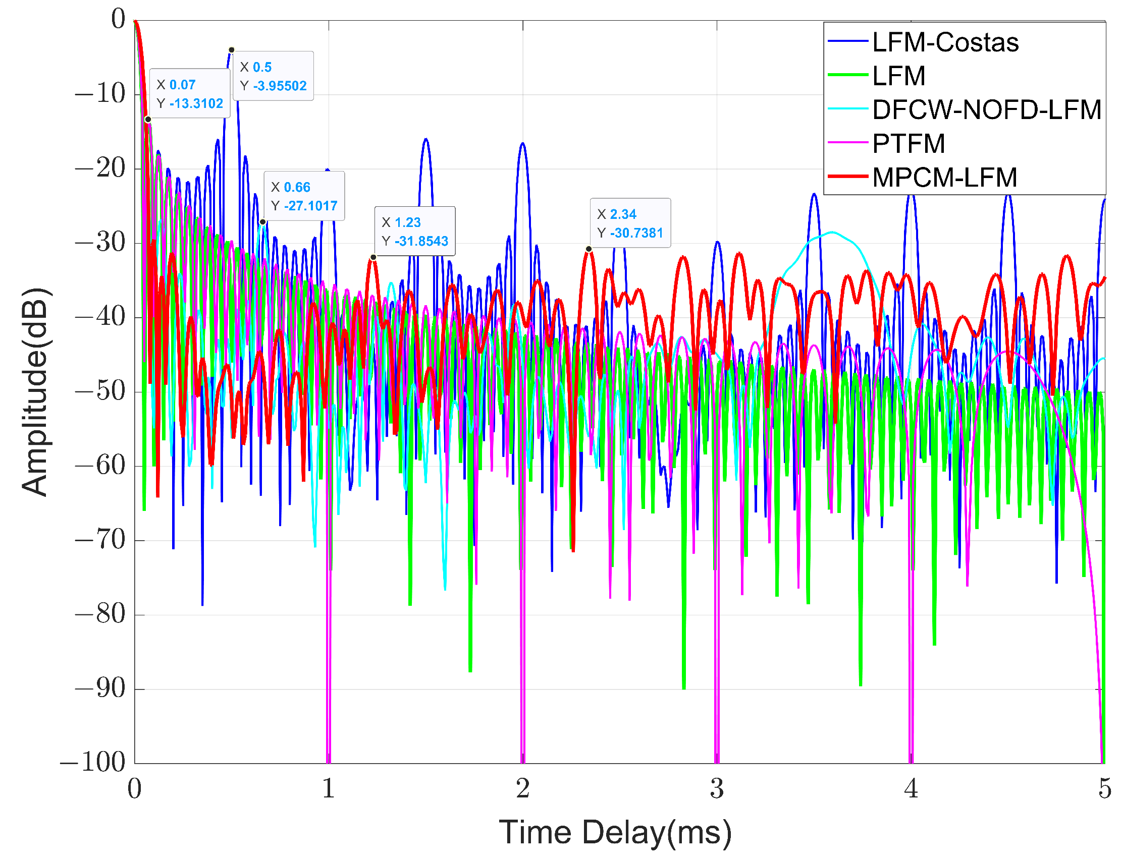
  • LFM signal: The pulse width of the LFM signal was 100 ms. The center frequency of the LFM was 20 kHz.
  • PTFM signal: It consisted of 10 LFM sub-pulses with a duration of 10 ms, and the bandwidth of the sub-pulse was 20 kHz.
  • LFM-Costas signal: It consisted of 10 LFM sub-pulses with a duration of 10 ms. The bandwidth of the sub-pulse was 2 kHz, and the frequency modulation sequence was C n = { 2 , 4 , 8 , 5 , 10 , 9 , 7 , 3 , 6 , 1 } .
  • DFCW-NOFD-LFM signal: The bandwidth range is 15–35 KHz, and the genetic algorithm was employed to acquire a sequence of non-uniform frequency spacing coefficients M = { 22.287823 , 22.893909 , 22.206368 , 22.089862 , 22.595781 , 23.063251 } and an initial phase sequence ϕ = { 15.135 , 12.002 , 11.315 , 15.125 , 10.328 , 15.171 , 12.627 } , with a sub-pulse bandwidth of B p = B ( N 1 ) · max ( Δ f ) 10 , 313 Hz .

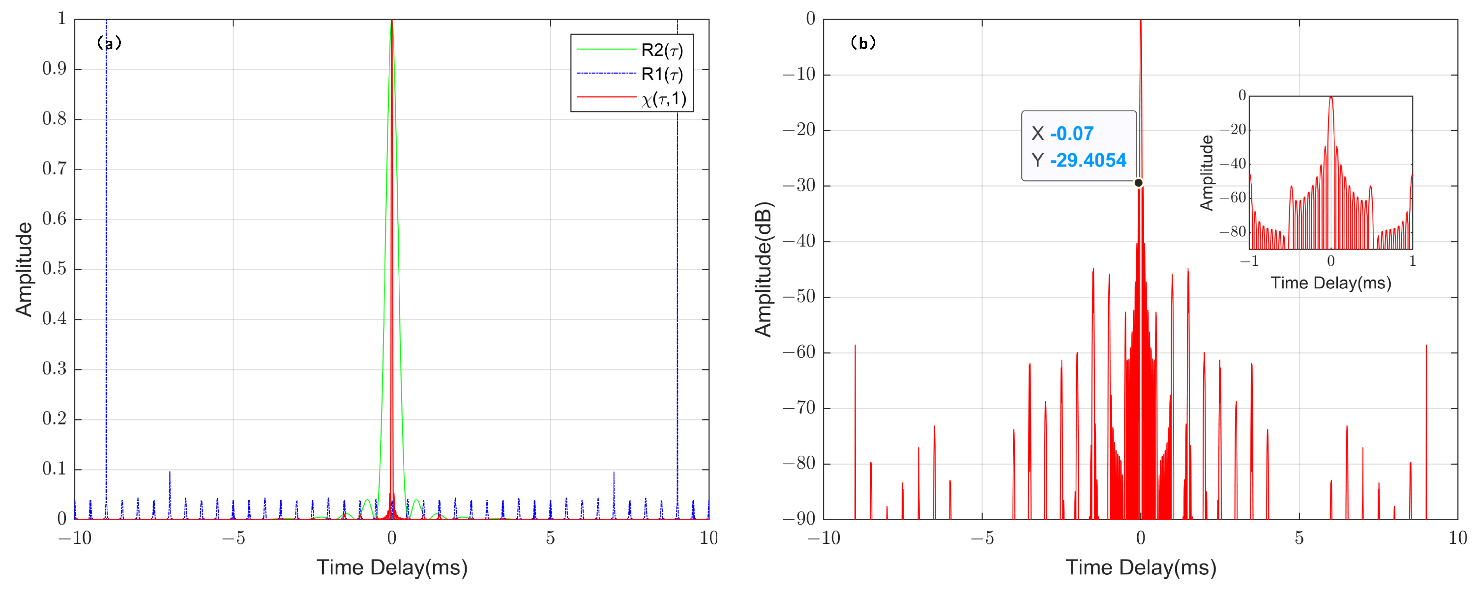
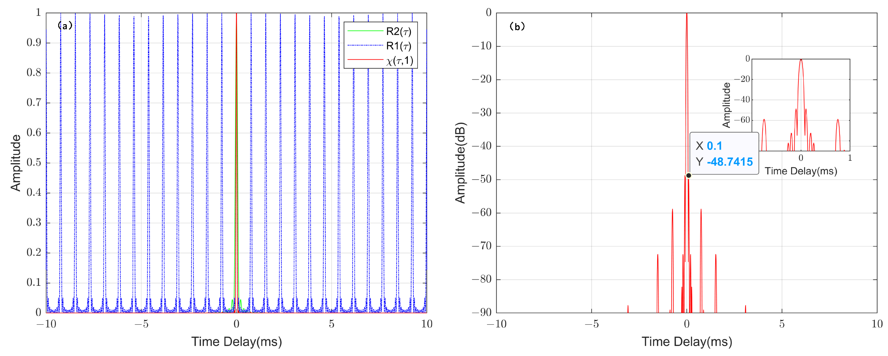
4.2. Results and Comparative Analysis of Range Ambiguity Function and Q-Function

Based on the above waveform parameters, we simulate the improved MPCM-LFM signal in the time domain and frequency domain, and its three-dimensional ambiguity function results are shown in Figure 10. It is apparent that the spectral envelope is similar to the shape of the Gaussian function, and the ambiguity function shows show a “near-thumbtack” shape, which has ideal time–Doppler resolution. The simulation results are consistent with the theoretical analysis. In addition, the simulation results of the comparison between the range ambiguity function (center ambiguous zone) and Q-function of the improved MPCM-LFM with other waveforms (LFM, LFM-Costas, PTFM and DFCW-NOFD-LFM [14] signals) are shown in Figure 11 and Figure 12.
The simulation results in Figure 11 clearly show that the maximum range sidelobe of the improved MPCM-LFM signal in the center ambiguous zone is about −31 dB, which is 17 dB, 17 dB and 27 dB lower than those of the base-pulse LFM signal, the PTFM signal and the LFM-Costas signal, respectively. The results demonstrate that the parameter improvement approach effectively removes the effect of the grating while extremely suppressing the range sidelobe. It also achieves a 4 dB reduction in the sidelobes compared to the DFCW-NOFD-LFM [14]. Although the suppression performance is not significantly improved, the DFCW-NOFD-LFM signal needs to be combined with a genetic algorithm for searching and optimizing the frequency spacing as well as the initial phase to improve the range sidelobe problem, which is more complicated than our proposed parameter-based improvement algorithm. Therefore, the combined results verify that the sidelobe suppression performance of the proposed improved MPCM-LFM outperforms that of the other signals.
We describe the results of the Q-function comparison in Figure 12, which show that the improved MPCM-LFM signal maintains the lowest Q-function value in the range of 0 m/s–5 m/s, except the Q-function value at the velocity of 0.45 m/s–2 m/s is slightly higher than the PTFM signal. This suggests that it has good detection performance for stationary and low-speed moving targets in the background of reverberation.

4.3. Discussion Analysis of Detection and Estimation Performance for the Improved MPCM-LFM Signal

Finally, we verify the detection performance of the improved MPCM-LFM signal for low-speed moving targets and its ability to achieve high-precision parameter estimation with the help of a simple matching correlation detection algorithm. Setting the target information, the target distance is 350 m and the motion speed is 2.5 m/s. The detection performance curves of the improved MPCM-LFM signal and other waveforms (LFM, LFM-Costas, PTFM and DFCW-NOFD-LFM signals [14]) in the background of the reverberation and the results of the root mean-square error (RMSE) curves for range estimation with different SRR are shown in Figure 13. The number of Monte Carlo experiments were set to 10,000 times and 5000 times, respectively.
From the results in Figure 13a, it is clear that superior detection performance is seen for the improved MPCM-LFM signal. In particular, the detection performance is significantly improved in the range of SRR from 0 dB to 4 dB, with an average enhancement of near 50% compared with the other signals. The detection curves show results compliance with the analysis of the reverberation suppression performance for different waveforms characterized through the Q-function. Furthermore, according to the results in Figure 13b, the classical waveform LFM suffers from the delay–Doppler coupling problem and has poor range estimation performance at low SRR. The PTFM signal has multiple high-correlation peaks due to spectral combing, and when the target deviates from the optimal detection velocity, the interference greatly affects the accuracy of the parameter estimation. The LFM-Costas signal solves the delay–Doppler coupling of the wideband FM signal to a certain extent, but its estimation performance decreases at low SRR due to the higher-range ambiguity sidelobe. The DFCW-NOFD-LFM signal suppresses the grating to a certain extent due to the setting of the non-uniform frequency spacing and initial phase, and the range estimation error is lower than that of other classical waveforms at SRR less than −8 dB. However, at different SRR from −10 to 10 dB, the improved MPCM-LFM signal has the lowest RMSE for range estimation and the fastest decrease in ranging error. Overall, our proposed parameter improvement method is one that obtains excellent results for the designed MPCM-LFM waveform, which effectively suppresses the range sidelobe and makes the signal possess the ability for high-precision parameter estimation.

5. Conclusions

In this paper, we proposed a novel high-resolution wideband waveform called MPCM-LFM, which improves the complexity and design flexibility of the waveform by combining the modulation of multiple parameters. Moreover, we deduced the wideband ambiguity function of the designed waveform from the definition of the wideband ambiguity function, and obtained a specific mathematical expression for the range ambiguity function. Theoretically, variation of the combination of waveform parameters affects the performance of sidelobe suppression, so we combined the performance of the MPCM-LFM signal in the time–frequency domain, deduced the constraint relationship of waveform parameters with different sub-band overlaps, and analyzed in detail the influence of waveform parameters on the range ambiguity function under different constraints. To overcome the shortcoming of the signal to further improve performance for suppressing grating as well as the high-range sidelobe, we also proposed a hopping carrier frequency constraint rule to optimize the spectral performance on the basis of theoretical analysis. By this parameter improvement method, the suppression of the periodic grating could be realized while significantly reducing the range ambiguity sidelobe. Finally, we analyzed the computer simulation results. It is obvious that our proposed waveform parameter improvement method led to good results. Compared with other classical waveforms, the improved MPCM-LFM waveform reduced the sidelobe level in the desired region by at least 17 dB. The detection performance curves and the range estimation RMSE curves also provided evidence of the correctness of the theoretical analysis, which proved that the designed waveform shows good performance in detecting stationary and low Doppler targets with optimal resolution, and is capable of realizing high-precision parameter estimation.
However, we simply analyze the designed waveform detection performance using the matching correlation detection algorithm in this paper. In future work, the exploration of optimal detectors specifically designed for the MPCM-LFM signals will be conducted to further enhance the detection performance of signals under low SRR conditions. Additionally, the effectiveness of the improved MPCM-LFM waveform and the proposed detection algorithm will be validated through external field experiments.

Author Contributions

Conceptualization, T.D. and H.L.; methodology, T.D.; software, T.D.; validation, T.D.; formal analysis, T.D.; investigation, T.D. and Z.D.; resources, T.D.; data curation, T.D.; writing—original draft preparation, T.D.; writing—review and editing, T.D. and L.Y.; visualization, Z.D. and L.Y.; supervision, H.L.; project administration, H.L.; funding acquisition, H.L. All authors have read and agreed to the published version of the manuscript.

Funding

This research was funded by the National Nature Science Foundation of China, grant number 61971354 and the National Nature Science Foundation of China, grant number 62371394.

Data Availability Statement

Not applicable.

Conflicts of Interest

The authors declare no conflict of interest.

Abbreviations

The following abbreviations are used in this manuscript:
MPCM-LFMMulti-parameter coded modulation LFM pulse
FMFrequency modulation
DSDoppler sensitivity
DIDoppler insensitive
ACFAutocorrelation function
SRRSignal-to-reverberation ratio

References

  1. Sun, Y.; Willett, P.; Lynch, R. Waveform fusion in sonar signal processing. IEEE Trans. Aerosp. Electron. Syst. 2004, 40, 462–477. [Google Scholar] [CrossRef]
  2. Doisy, Y.; Deruaz, L.; van IJsselmuide, S.P.; Beerens, S.P.; Been, R. Reverberation suppression using wideband Doppler-sensitive pulses. IEEE J. Ocean. Eng. 2008, 33, 419–433. [Google Scholar] [CrossRef]
  3. Hague, D.A.; Buck, J.R. The generalized sinusoidal frequency-modulated waveform for active sonar. IEEE J. Ocean. Eng. 2016, 42, 109–123. [Google Scholar] [CrossRef]
  4. Wang, Y.; He, Y.; Wang, J.; Shi, Z. Comb waveform optimisation with low peak-to-average power ratio via alternating projection. IET Radar Sonar Navig. 2018, 12, 1012–1020. [Google Scholar] [CrossRef]
  5. Hague, D.A.; Buck, J.R. An experimental evaluation of the generalized sinusoidal frequency modulated waveform for active sonar systems. The J. Acoust. Soc. Am. 2019, 145, 3741–3755. [Google Scholar] [CrossRef]
  6. Pecknold, S.P.; Renaud, W.M.; McGaughey, D.R.; Theriault, J.A.; Marsden, R.F. Improved active sonar performance using Costas waveforms. IEEE J. Ocean. Eng. 2009, 34, 559–574. [Google Scholar] [CrossRef]
  7. Li, H.; Liu, Y.; Liao, G.; Chen, Y. Joint Radar and Communications Waveform Design Based on Complementary Sequence Sets. Remote Sens. 2023, 15, 645. [Google Scholar] [CrossRef]
  8. Jiang, J.; Sun, Z.; Duan, F.; Liu, W.; Wang, X.; Li, C.; Bu, L.; Fu, X.; Huang, T.; Ma, L. Disguised Bionic Sonar Signal Waveform Design With its Possible Camouflage Application Strategy for Underwater Sensor Platforms. IEEE Sens. J. 2018, 18, 8436–8449. [Google Scholar] [CrossRef]
  9. Xi, R.; Ma, D.; Liu, X.; Wang, L.; Liu, Y. Intra-Pulse Frequency Coding Design for a High-Resolution Radar against Smart Noise Jamming. Remote Sens. 2022, 14, 5149. [Google Scholar] [CrossRef]
  10. Pralon, L.; Beltrao, G.; Pompeo, B.; Pralon, M.; Fortes, J.M. Near-thumbtack ambiguity function of random frequency modulated signals. In Proceedings of the 2017 IEEE Radar Conference (RadarConf), Seattle, WA, USA, 8–12 May 2017; pp. 0352–0355. [Google Scholar]
  11. Pakdel Azar, O.; Amiri, H.; Razzazi, F. Enhanced target detection using a new combined sonar waveform design. Telecommun. Syst. 2021, 77, 317–334. [Google Scholar] [CrossRef]
  12. Huang, Q.-d.; Li, Y.; Lu, G.-y. Design and analysis of inter-pulse costas frequency hopping and intra-pulse multi-carrier chaotic phase coded radar signal. J. Electron. Inf. Technol. 2015, 37, 1483–1489. [Google Scholar]
  13. Costas, J.P. A study of a class of detection waveforms having nearly ideal range—Doppler ambiguity properties. Proc. IEEE 1984, 72, 996–1009. [Google Scholar] [CrossRef]
  14. Xu, Y.; Xue, M.; Liu, M.; Hao, C.; Zhao, L.; Wang, J.; Zhou, Z. Wideband Waveform Design and Performance Analysis for Multiple Unmanned Underwater Vehicle Cooperative Detection Sonar. J. Electron. Inf. Technol. 2023, 45, 1–9. [Google Scholar]
  15. Neuberger, N.; Vehmas, R. A Costas-based waveform for local range-Doppler sidelobe level reduction. IEEE Signal Process. Lett. 2021, 28, 673–677. [Google Scholar] [CrossRef]
  16. Neuberger, N.; Vehmas, R. Range sidelobe level reduction with a train of diverse LFM pulses. IEEE Trans. Aerosp. Electron. Syst. 2021, 58, 1480–1486. [Google Scholar] [CrossRef]
  17. Guan, C.; Zhou, Z.; Zeng, X. Optimal waveform design using frequency-modulated pulse trains for active sonar. Sensors 2019, 19, 4262. [Google Scholar] [CrossRef]
  18. Zhao, D.; Wei, Y.; Liu, Y. Hopped-frequency waveform design for range sidelobe suppression in spectral congestion. IET Radar Sonar Navig. 2018, 12, 87–94. [Google Scholar] [CrossRef]
  19. Long, T.; Li, Y.; Zhang, W.; Liu, Q.; Chen, X.; Tian, W.; Yang, X. Wideband Radar Signal and Waveform Design. In Wideband Radar; Springer Nature: Singapore, 2022; pp. 13–39. [Google Scholar]
  20. Richards, M.A. Basic principles. In Principles of Modern Radar; Sheridan Books, Inc.: Chelsea, MI, USA, 2010. [Google Scholar]
  21. Hague, D.A. Adaptive transmit waveform design using multitone sinusoidal frequency modulation. IEEE Trans. Aerosp. Electron. Syst. 2020, 57, 1274–1287. [Google Scholar] [CrossRef]
  22. Wang, Q.; Wei, X.; Gao, M. Stepped frequency signal property analysis based on Ambiguity function. In Proceedings of the 2022 IEEE 6th Information Technology and Mechatronics Engineering Conference (ITOEC), Chongqing, China, 4–6 March 2022; Volume 6, pp. 1503–1509. [Google Scholar]
  23. Yue, L.; Liang, H.; Duan, T.; Dai, Z. A Reverberation Suppression Method Based on the Joint Design of a PTFM Waveform and Receiver Filter. Entropy 2022, 24, 1707. [Google Scholar] [CrossRef] [PubMed]
  24. Dash, D.; Jayaraman, V. Ambiguity function analysis for orthogonal-LFM waveform based multistatic radar. IEEE Sens. Lett. 2021, 5, 1–4. [Google Scholar] [CrossRef]
  25. Fu, Y.; Li, Y.; Lu, G.; Zhang, K. Design and analysis of interpulse hybrid frequency modulation and intrapulse phase-coded radar signal. J. Harbin Eng. Univ. 2019, 40, 1347–1353. [Google Scholar]
  26. Mason, S.F.; Berger, C.R.; Zhou, S.; Willett, P. Detection, synchronization, and Doppler scale estimation with multicarrier waveforms in underwater acoustic communication. IEEE J. Sel. Areas Commun. 2008, 26, 1638–1649. [Google Scholar] [CrossRef]
  27. Mao, Z.; Wei, Y. Interpulse-frequency-agile and intrapulse-phase-coded waveform optimisation for extend-range correlation sidelobe suppression. IET Radar Sonar Navig. 2017, 11, 1530–1539. [Google Scholar] [CrossRef]
  28. Yang, Y.; Kang, J.S.; Park, J.; Guvenc, I.; Kim, H.; Jeong, B.J. Stepped-Carrier OFDM with a Nonlinear Hopping Pattern for Joint Radar and Communications. IEEE Sens. J. 2022, 22, 24619–24633. [Google Scholar] [CrossRef]
  29. Rihaczek, A.W. Delay-Doppler ambiguity function for wideband signals. IEEE Trans. Aerosp. Electron. Syst. 1967, AES-3, 705–711. [Google Scholar] [CrossRef]
  30. Wiener, N. Generalized harmonic analysis. Acta Math. 1930, 55, 117–258. [Google Scholar] [CrossRef]
Figure 1. Schematic diagram of waveform design.
Remotesensing 15 04603 g001
Figure 2. Time–frequency domain performance in different signals. (a) LFM pulse. (b) Standard OFDM signal. (c) OFDM signal satisfying band and time-width constraints. (d) Linear stepping time–frequency domain performance. (e) Time–frequency hopping. (f) Designed MPCM-LFM signals, with the colors representing the different sub-pluses modulation properties.
Remotesensing 15 04603 g002
Figure 3. MPCM-LFM signals with different overlaps of sub-bands. (a) Separate sub-bands without overlap. (b) Low overlap of sub-bands. (c) High overlap of sub-bands. (The colors represent the different sub-pluses modulation properties).
Remotesensing 15 04603 g003
Figure 4. MPCM-LFM signal with separate sub-bands, non-overlapping (Constraint 1). (a) R 1 t , R 2 t , and χ τ , 1 . (b) Wideband range correlation function (in dB).
Remotesensing 15 04603 g004
Figure 5. MPCM-LFM signal with low overlap of sub-bands (Constraint 2). (a) R 1 t , R 2 t , and χ τ , 1 . (b) Wideband range correlation function (in dB).
Remotesensing 15 04603 g005
Figure 6. MPCM-LFM signal with high overlap of sub-bands (Constraint 3). (a) R 1 t , R 2 t , and χ τ , 1 . (b) Wideband range correlation function (in dB).
Remotesensing 15 04603 g006
Figure 7. The high sub-bands overlap MPCM-LFM signal with an increased sub-pulse bandwidth and its improved form. (The colors represent the different sub-pluses modulation properties).
Remotesensing 15 04603 g007
Figure 8. Range correlation function of MPCM-LFM signal after improving waveform parameters. (a) R 1 t , R 2 t , and χ τ , 1 . (b) Wideband range correlation function (in dB).
Remotesensing 15 04603 g008
Figure 9. Comparison of range correlation function between the improved waveform and the MPCM-LFM signals under the previous three parameter constraints.
Remotesensing 15 04603 g009
Figure 10. Improved MPCM-LFM signal. (a) MPCM-LFM in time domain. (b) MPCM-LFM in frequency domain. (c) Ambiguity function of improved MPCM-LFM signal.
Remotesensing 15 04603 g010
Figure 11. Simulation results of range ambiguity function (center ambiguous zone) for different waveforms.
Remotesensing 15 04603 g011
Figure 12. Q-function results for different waveforms.
Remotesensing 15 04603 g012
Figure 13. Comparison results of ROC curves and RMSE curves for different signals. (a) ROC curves for different SRR. (b) RMSE curve for range estimation.
Remotesensing 15 04603 g013
Table 1. Relationship of waveform parameters under the different sub-pulse bandwidth constraints.
ConstraintCorresponding Parameter RelationshipSub-Bands Overlap Results
Sub-Pulse Bandwidth B p Relationship between m and N Sub-Pulse Carrier Frequency f n
1 B p Δ f 2 m B N · T p f n = f 0 B / 2 + C n 1 · Δ f Separate sub-bands without overlap
2 Δ f 2 < B p Δ f m B N · T p f n = f 0 B / 2 + C n 1 · Δ f Low overlap of sub-bands
3 Δ f < B p B f X N 1 Δ f m 2 B     f X T p 2 N     2 f n = f 0 B / 2 + B p / 2 + C n 1 · Δ f High overlap of sub-bands
Table 2. The sidelobe levels of the wideband range correlation functions for the MPCM-LFM waveforms under the three constraints and the improved MPCM-LFM.
MPCM-LFM WaveformSidelobe Level (dB)
Constraint 1−8.71868
Constraint 2−29.4054
Constraint 3−48.7415
After improvement−67.2258
Table 3. Waveform parameter settings.
Parameter SettingValue
Signal pulse width100 ms
Baseband frequency range15–35 KHz
Number of sub-pulses N10
Sub-pulse frequency interval Δ f 833 Hz
Sub-pulse bandwidth12,500 HZ
Disclaimer/Publisher’s Note: The statements, opinions and data contained in all publications are solely those of the individual author(s) and contributor(s) and not of MDPI and/or the editor(s). MDPI and/or the editor(s) disclaim responsibility for any injury to people or property resulting from any ideas, methods, instructions or products referred to in the content.

