Article

Investigation on Geometry Computation of Spaceborne GNSS-R Altimetry over Topography: Modeling and Validation

1
School of Earth Sciences and Engineering, Hohai University, Nanjing 211100, China
2
German Research Centre for Geosciences (GFZ), 14473 Potsdam, Germany
3
Earth Observation Research Group, Institute of Space Sciences, Spanish National Research Council (ICE, CSIC), 08193 Barcelona, Spain
4
Institut d’Estudis Espacials de Catalunya (IEEC), 08034 Barcelona, Spain
5
Institute of Geodesy and Geoinformation Science, Technische Universität Berlin, 10623 Berlin, Germany
*
Author to whom correspondence should be addressed.
Remote Sens. 2022, 14(9), 2105; https://doi.org/10.3390/rs14092105
Submission received: 8 March 2022 / Revised: 20 April 2022 / Accepted: 25 April 2022 / Published: 27 April 2022
(This article belongs to the Special Issue Applications of GNSS Reflectometry for Earth Observation II)

Abstract

:
The spaceborne Global Navigation Satellite Systems Reflectometry (GNSS-R) offers versatile Earth surface observation. While the accuracy of the computed geometry, required for the implementation of the technique, degrades when Earth’s surface topography is complicated, previous studies ignored the effects of the local terrain surrounding the ideal specular point at a suppositional Earth reference surface. The surface slope and its aspect have been confirmed that it can lead to geolocation-related errors in the traditional radar altimetry, which will be even more intensified in tilt observations. In this study, the effect of large-scale slope on the spaceborne GNSS-R technique is investigated. We propose a new geometry computation strategy based on the property of ellipsoid to carry out forward and inverse calculations of path geometries. Moreover, it can be extended to calculate unusual reflected paths over versatile Earth’s topography by taking the surface slope and aspects into account. A simulation considering the slope effects demonstrates potential errors as large as meters to tens kilometers in geolocation and height estimations in the grazing observation condition over slopes. For validation, a single track over the Greenland surface received by the TechDemoSat 1 (TDS-1) satellite with a slope range from 0% to 1% was processed and analyzed. The results show that using the TanDEM-X 90 m Digital Elevation Model (DEM) as a reference, a slope of 0.6% at an elevation angle of 54 degrees can result in a geolocation inaccuracy of 10 km and a height error of 50 m. The proposed method in this study greatly reduces the standard deviation of geolocations of specular points from 4758 m to 367 m, and height retrievals from 28 m to 5.8 m. Applications associated with topography slopes, e.g., cryosphere could benefit from this method.

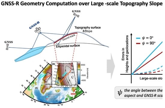
Graphical Abstract

1. Introduction

The forward scattering passive-mode reflectometry technique, using GNSS signals, exhibits a great potential for Earth observation with an exceptionally high spatial and temporal resolution [1]. This novel remote sensing approach has been evolved from ocean altimetry [2,3,4] to diverse Earth surface investigations, such as sea surface winds retrieval [5,6,7], cryosphere detection [8,9], land geophysical parameters inversion [10,11,12], and potentially precipitation detection over calm oceans [13,14]. Since GNSS-R altimetry was proposed for the first time [15], numerous studies on the height estimation have led to the development of ground-based [16,17], airborne [18,19], and spaceborne [20,21] Earth observation systems.
However, the data processing and validity of observations for all those geolocation-related GNSS-R applications require exact geometric computations [22,23]. For the GNSS-R altimetry, a three-dimension computation of the geolocation and height information is needed, which are calculated by a specular point algorithm and geometric processing on propagation length. Specular point calculation is one of the key aspects of geometry computation. In addition to specifying the geolocation of the measurements, the code phase offset and doppler information are also derived to collaborate the onboard real-time open-loop processing of the reflected signals [24]. Accurate estimations can ensure the efficiency of open-loop processing and increase the potential to track the reflection from the diverse Earth’s surfaces. The numerical method derived in [15] is based on an approximate spherical Earth. Although this approach benefits from the one-time calculation of solving a quartic polynomial, it suffers from an unacceptable error due to the Earth’s curvature [25]. A quasi-spherical Earth approach was added to improve this non-iterative method, and a significant improvement was achieved. This method was applied in the TDS-1 mission for real-time processing [25]. Large geolocation errors close to unacceptable limits still existed, which is not suitable for all situations when errors are further considered [25]. More than 3 km errors can be found by investigating the metadata of TDS-1 products. Besides the numerical approaches, several approaches using the iterative calculation were presented based on the method of steepest descent [23,26,27]. Those methods can converge to the best solution at a considerable computational cost. Studies in [24] revealed that the precise estimation of the specular point still dominates the computation demand in the tracking algorithm, which currently was mainly limited by the correction factor in the iterative calculation and tolerance of the convergence. Modifications for the acceleration of iterative computations by improving the steepest descent still suffer from a mean number of more than 80 iterations at a strict stopping condition of 0.1m distance tolerance. Nevertheless, the estimation error, with a maximum of approximately 20 km, cannot be effectively eliminated due to the effect of the curvature as the specular point approaches mid-latitude and when the incidence angle gradually increases [23]. Alternatively, an improved method to reduce curvature errors by applying an osculating sphere (OS) was analyzed [28,29]. This method requires a precise initial input to firstly find the local osculating sphere and estimate the specular point iteratively. However, it has been found that large angular and propagation length errors occur at intermediate latitudes [23].
It should be noted that calculation over a large number of iterations will occupy more computational resources if future satellites operate for grazing condition observations. In such a geometry the error sources will be larger and more significant [27]. Too many iterations are generally caused by an inaccurate initial estimation, especially for the high-incidence situations. The traditional initial estimation is usually given roughly by (a) the sub-satellite point of the receiver normalized to the Earth’s surface [24] or (b) a height-weight method given in [25,30]. Both methods are currently insufficient to obtain precise initialization to significantly increase the speed of convergence, whose performance significantly degrades at high incidence angles. As discussed in [24], a much more accurate initialization can be done simply by further correcting the previous specular point of the same track. However, more complicated additional budgets will be required to support the interpolated prediction. Since the shape of the Earth and the motion of the satellite are geometrical properties (ellipsoidal shape and approximately fixed orbit height), it is possible to obtain accurate enough initializations by empirical methods, which is one of the breakthroughs of this paper. Nevertheless, the ocean situation is relatively not difficult to be addressed. Once the reflection point crosses over land, the situation becomes more complicated due to the diverse terrain topography. In [22], a new perspective according to the shortest total length and angular criteria based on the Digital Elevation Model (DEM) model is studied to determine the specular region. However, it adds additional computation costs to geolocate each measurement. In addition, it cannot be combined with bistatic observations for further altimetric implementation.
Another aspect of the geometry computation in altimetry is the determination of the propagation path of the reflected signal with a known path delay, in which the height of the reflective surface information must be determined. Specifically, GNSS-R altimetry is based on the path range observation to estimate the surface height, and the propagation path may no longer be the Earth’s ellipsoid surface but the surface topography. Accordingly, the measurements should be corrected to the topography. On the ocean, the reflective surface is smooth and flat with a stable topography, which is conducive to reflecting the signals from a specific quasi-specular region to the receiver. Nevertheless, the specular point is still affected by the ocean topography [31]. In addition, due to the discrepancy between the Earth’s ellipsoid and the gravity field, predictable errors in path length have been considered in the calibration of CYGNSS products [32]. An initial simulation integrating the DEM model to find the trajectories within the scattering plane also highlighted the importance of the Earth’s topography in geometry computation [27]. As a result, the surface height estimation model with the observed delay as input and taking into account the surface topography (surface height, and surface slope) is another important part of the geometry computation in the GNSS-R altimetry.
In a spaceborne scenario, the path delay observation can be retrieved utilizing the waveform retracker algorithm [2,33]. After careful corrections of propagation errors [34,35], the exact observation delay can be obtained. Currently, several estimation models are based on the difference between the observed delay and the modeled delay derived at the estimated specular points [36]. A typical model proposed in [15], has been widely applied and validated in [20,34,37], which is based on the delay difference approximation estimation. In that method:
Δ ρ = ( ρ m ρ o )
H s u r f = Δ ρ 2 s i n θ
where ρ o is the bistatic observed delay and ρ m is the bistatic model delay of the reflected signal, Δ ρ is the difference between the observed and model path ranges, H s u r f is the reflective surface height with respect to the reference surface. θ is the elevation angle at the specular point. Applying this method, one should be careful to control the height difference between the reference surface and the true reflecting surface. Furthermore, the large-scale slope of the reflective surface is not considered. Theoretically, a geolocation offset of 1 km in the horizontal direction can lead to a height deviation of 5 m for a fixed slope of 0.5%. Another model proposed in [38] and used in [39] is based on the iterative computation of geometry. It takes into account the three-dimension variations of the specular point at different reflective heights. However, the Earth’s sphere model is used to scale the iterative estimation on the sphere surface. The geometric method proposed in [21], applied to estimate the large-scale topography of the sea surface, takes only the offset of the specular point in the normal direction into account, similar to the first method but with different equations.
As a result, most of the specular point algorithms or surface height estimation models are based on the assumption that the reflecting surface is parallel to the tangent plane at the specular point on the Earth reference ellipsoid to compute the geometry conveniently. On the other hand, the surfaces are normally inclined to the tangent plane on land reflection surfaces. The ocean surface also has a small topography slope, which is ignored by the traditional specular point estimation algorithms. However, it has been considered in the radar altimetry [40], which is a more pressing issue for GNSS-R technology. In [41,42], the impact of local small-scale slope and topography data on the spaceborne observations are investigated. In [43,44], the application of the DEM retrieval using the GNSS-R technique has been investigated. Large errors can be found due to the large-scale slope of the reflective surface in the cryosphere area when the geometric method proposed in [21] was applied. Slope impact on the traditional radar altimetry is also a severe issue, which can be improved with several methods found in [45,46]. Overall, the geometry computation in GNSS-R altimetry should be improved to accommodate more natural scenarios, in which the Earth’s curvature and surface topography are included. Here, a new comprehensive geometry computation strategy, suitable for the relatively smooth and large-scale slope situation, is proposed.
This paper is organized as follows. Section 2 describes the proposed ellipsoid-based geometry computation strategy in detail. Section 3 further focuses on the geometry computation over topography based on the proposed strategy. Dataset and results are presented in Section 4. Section 5 provides some discussions regarding several factors on this method. Finally, the conclusions are given in Section 6.

2. Ellipsoid-Based Geometry Computation Strategy

2.1. Observation-Driven GNSS-R Geometry Computation

In the GNSS-R geometry, the positions of the transmitter and receiver are the fundamental requirements. The position of the satellites can be obtained by the International GNSS Service (IGS) [47] and using positioning techniques or directly collected from the metadata, such as those of TDS-1 and CYGNSS [48]. With these two satellites’ positions and an observed reflected signal propagation range, an ellipsoid in space with the positions of both satellites as the focal points and observed path range ρ o of reflected signal as the major axis can be created. This ellipsoid is the set of all virtual specular points that satisfy the propagation range of reflected signals, here named path equal ellipsoid. As for this spatial geometry, it provides a special perspective to calculate the specular point according to the ellipsoidal mirror reflection. With an ellipsoid in space, the normal of the tangent plane at a point on the ellipsoid bisects the angle between the point and the two focal points. In other words, in an ellipsoid, when electromagnetic waves depart from a focal point and reflect on the inner wall of the ellipsoid, the reflected waves will always pass through another focal point, which is consistent with the geometry of the GNSS signals reflection events. Therefore, a more accurate and rigid model for geometry computation can be designed, and the specular point calculation is transformed to find the tangent point between the path equal ellipsoid and Earth ellipsoid.
In the case of specular reflection on an Earth’s ellipsoidal surface, there is only one specific specular point on the ellipsoidal surface. This normal vector at the specular point on Earth’s ellipsoid surface is also the normal vector at the tangent point on the path equal ellipsoid, thus the common normal vector will bisect the angle between the vectors from the tangent point to two focal points, which coincides with the definition of the specular reflection point. If the positions of both the transmitter and receiver are determined, the specular point on the ellipsoidal surface is fixed as there is only one common tangent point with the minimum path length. The position of the specular point is therefore dependent on the path range of the reflected signal. As a result, the path range of the reflected signal determines the specular point and the height of the reflected surface, as shown in Figure 1.
The transmitter ( T x ( x T , y T , z T ) ) and receiver ( R x ( x R , y R , z R ) ), and true specular point ( S x ( x S , y S , z S ) ) on the WGS84 ellipsoidal surface are in the same plane according to the law of reflection. The transmitter ( T x ) and receiver ( R x ) are the focal points of “Ellipsoid 1” and “Ellipsoid 2”. The “Ellipsoid 2” is formed corresponding to the observed path range ρ o of the reflected signal, and the specular point S x is the tangent point between the path equal ellipsoid (Ellipsoid 2) and new Earth ellipsoid modified based on the WGS84 ellipsoid by adding a scale factor ς , which associates with the surface height h . Its semi-major and semi-minor axes are expressed by:
r m a j o r = ( 1 + ς ) r m a j o r W G S 84
r m i n = ( 1 + ς ) r m i n W G S 84
where r m a j o r W G S 84 and r m i n W G S 84 are the semi-major and semi-minor axis of the WGS84 ellipsoid, and r m a j o r , r m i n are the semi-major and semi-minor of the new Earth ellipsoid. The scale factor, ς , is an unknown to be determined as well as the new specular point S x which is an important parameter that can be used against the impact of the Earth’s surface curvature on the surface height estimation. The scale factor varies with the surface height increase and adds the curvature effect in the geometry computation. Overall, the idea of this method is to calculate the scale factor and the specular point S x simultaneously from the perspective of the special relationship between the ellipsoid and GNSS-R geometry associated with the positions of transmitter and receiver and the observed path range.
In Figure 1, the normal of the tangent plane at S x bisects the angle formed by the point S x and the two focal points, and the S x is on the ellipsoid with receiver and transmitter as the focal points and | R x S x | + | T x S x | as the major axis of the “Ellipsoid 2” in Figure 1. By mathematical modeling, the equation of the equal path range ellipsoid can be expressed as a function of the reflection geometric parameters:
Γ o ( x , y , z ) = f ( R x , T x , ρ o )
where ρ o is the observed geometric path range of the reflected signal after correcting propagation errors, which determines the ellipsoid with receiver and transmitter. Γ o = f ( ) is the equal range ellipsoid function with input variables of R x , T x , ρ o . Γ o = f ( ) can be further extended to:
Γ o ( x , y , z ) = ( x x R ) 2 + ( y y R ) 2 + ( z z R ) 2 + ( x x T ) 2 + ( y y T ) 2 + ( z z T ) 2 ρ o
In addition, the Earth’s surface can be presented by an ellipsoid deduced by the WGS84 ellipsoid, as follows:
Γ e a r t h ( x , y , z ) = x 2 r m a j o r 2 + y 2 r m a j o r 2 + z 2 r m i n 2
where r m a j o r , r m i n are the semi-major and semi-minor of the new Earth ellipsoid modified based on the WGS84 Earth ellipsoid by adding a scale factor ς , as denoted in Equations (3) and (4).
According to the analysis and ellipsoidal properties mentioned before, the specular point solution can be summarized as the problem of solving the external tangent point of these two ellipsoids. Therefore, the specular point is on the two ellipsoidal surfaces, and the normals at the tangent point are parallel. The normal vector on the Earth’s ellipsoidal surface at the specular point can be obtained by:
N x o = Γ o ( x , y , z ) x
N y o = Γ o ( x , y , z ) y
N z o = Γ o ( x , y , z ) z
where N o ( N x o , N y o , N z o ) is the normal vector at any point on the equal range ellipsoid. Similarly, the normal vector of the point on the Earth’s ellipsoidal surface can be represented as ( x r m a j o r 2 , y r m a j o r 2 , z r m i n 2 ) , which is simplified to N e ( N x e , N y e , N z e ) . For subsequent calculations, the N o and N e are normalized to a unit vector and in the following part, N o and N e are referred to as the unit vectors. Considering the directions of two normals, two situations where both two normals are in the same direction or reverse should be taken into account to build a system of equations to find the specular point solution with respect to the observed path range ρ o . When both normals are in the same direction, the following equations can be applied:
f 1 ( x , y , z ) = N x o N x e
f 2 ( x , y , z ) = N y o N y e
f 3 ( x , y , z ) = N z o N z e
Otherwise:
f 1 ( x , y , z ) = N x o + N x e
f 2 ( x , y , z ) = N y o + N y e
f 3 ( x , y , z ) = N z o + N z e
Combining that the specular point is on both ellipsoids, four unknowns:
X = [ x , y , z , ς ] T
are about to be calculated. Consequently, a set of four equations can be formed as follows:
Γ = { Γ o ( x , y , z ) = 0 Γ e a r t h ( x , y , z , ς ) = 0 f i ( x , y , z ) = 0 f j ( x , y , z ) = 0
where i , j = 1 , 2 , 3 . but i j . which is related to the coordinates. We need to avoid the impact on the iterative calculation when a coordinate component is close to zero. Γ is the system of the equations including four constraints to deduce the solution X . Apparently, the solution with four unknown variables can be obtained by the four independent equations. Since Γ is a nonlinear system of equations, the Newton–Raphson method [49] is employed to find the solution of Equation (18) with an iterative formula:
X n + 1 = X n Γ ( X n ) Γ ( X n )
The iterative stopping condition is set according to the Euclidean distance, Δ X , between the specular points for the n and n + 1 iterations. The initial input in the iterative calculation is important as introduced before. To ensure the convergence of the iterative computation, a new empirical model method for the initialization is given in Appendix A. In addition to the specular point on the new Earth ellipsoid, the scale factor ς , is initially set as 1. It is related to the geodetic height of the specular point but is not accurately determined due to the curvature of the ellipsoid. Once the specular point is calculated, a reasonable ellipsoidal height of the surface can be obtained by coordinate transformation as follows:
B , L , h = F e a r t h W G S 84 ( x , y , z )
where F e a r t h W G S 84 ( ) is the function to transform the coordinates ( x , y , z ) to the geodetic system represented by latitude B , longitude L , and ellipsoidal height h . As a result, the proposed method directly transforms the receiver, transmitter, and observed path ranges to the specular reflection point and its ellipsoidal height, which is different compared to previous studies.
In this strategy, the method can be modified to carry out other common geometry computations. For instance, if the observation ρ o is unknown, and we need to calculate the specular point on the WGS84 ellipsoid surface, then the scale factor ς can be replaced by the path length of the reflected signal ρ g . Then, four new unknowns are as follows:
X = [ x , y , z , ρ g ] T
where ρ g is the geometric path range of the reflected signal when the specular point is on the reference ellipsoidal surface.
Furthermore, if we already know the height of the specular region, we can set this height as a constrain to iteratively calculate the scale factor ς and specular point until the ellipsoid height of the iterative specular point is equal to the expected height. Following similar steps given above, the estimation of the new specular point, considering the surface height, can be carried out. Due to the quadratic convergence rate of the Newton–Raphson method, combining a greatly precise initialization, this calculation strategy can lead to high computational efficiency.

2.2. Comparisons of the Specular Point Calculation Performance

To investigate the calculation performance of the proposed ellipsoid-based geometry computation strategy, further comparisons with the traditional iterative method, called Minimum Propagation Length (MPL) [23], are presented. In this comparison, 500,000 simulations for an orbit height of 500 km of the receiver were conducted. The mean orbit height of the transmitter is 20,200 km, and a normal distribution error with a standard deviation of 200 km is added. We recorded the time consumption for each method to finish calculations for evaluation. Moreover, iterations, errors of Total Path Length (TPL), and Specular Points (SPs) with respect to the reference data are counted separately with an elevation angle of 30 degrees as the boundary. The iterative stopping condition of MPL is set as 0.1 m as the same in [23]. The iterative stopping threshold in the ellipsoid-based geometry computation strategy is also set as 0.1 m. The reference data are calculated by the ellipsoid-based method with a strict iterative stopping threshold, in which angular criteria (difference between the incidence and reflected angle) and distance criteria (difference between the radius of the WGS84 ellipsoid at specular point and its distance to the WGS84 ellipsoid center) are controlled to the magnitude of 1 × 10⁻¹⁰ degrees and 1 × 10⁻⁸ m respectively to ensure the high precision of each simulation. The results of the statistics are presented in Table 1.
In Table 1, it can be found that the ellipsoid-based iterative method (S#1) demonstrates quite high efficiency. The TPL and SPs errors are within 10 × 10−8 m, and mean iterations through all the geometric situations are close to 3 times. In fact, setting the stopping threshold to 100 m also ensures the precision of TPL and SPs higher than 5 × 10⁻⁵ m. In addition, a simplified approach based on S#1 still keeps the TPL and SPs errors less than 5 m, and the computational efficiency is improved by 58.3% in terms of time consumption compared to S#1 method. The MPL iterative method takes nearly 2.4 times longer than the S#1 method to complete the calculation with the same stopping threshold. Moreover, the number of iterations in the grazing angle condition is about 7 times higher than that in the other geometric conditions. Due to the Earth’s curvature, the results of MPL cannot converge to the true point. This results in the average errors of SPs reaching 6 km for elevation angles lower than 30 degrees and 2227 m for elevation angles higher than 30 degrees. The proposed empirical model shows the highest calculation efficiency, and the TPL and SPs errors are even less than the MPL method. In general, the S#3 and S#4 methods are suitable for onboard data processing on the satellites in terms of computational efficiency and accuracy of results. The first method is recommended to be used for more precise data processing and for applications on the ground.

3. Geometry Computation Based on Topography

For GNSS-R geometry computation over the natural Earth’s surface, two factors should be noticed. The first primary factor is the height of the terrain nearby the specular point. The significant Earth’s surface height can lead to a considerable shift in the estimation of the measurement location when taking the WGS84 ellipsoidal surface as a reference. The proposed method introduced above can address this issue. Another important and complex consideration is the surface slope where the signal is reflected. In general, the incidence and reflected angles are equal with respect to the tangent plane to the Earth’s ellipsoid surface at the specular point, whereas the topography over land changes this principle due to the surface slope and its aspect. Normally, the signal tends to be reflected over a tilted surface ensuring the shortest length path according to Fermat’s principle [23]. The issues caused by the large-scale topography slope are ignored in previous altimetric methods. In the following part, an extended method for geometry computation over topography is presented.

3.1. True Specular Area Determination Based on Topography

3.1.1. Local Area Searching Based on the Initial Specular Point

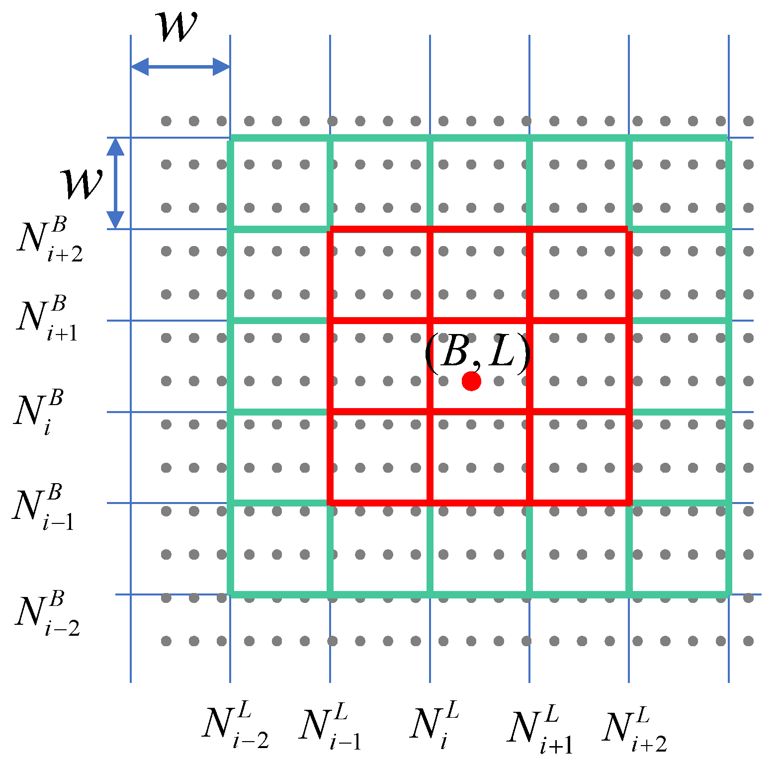
Implementing a fast search of a local area corresponding to a specular point in the global topography map is a quite time-consuming process for each reflection. Therefore, firstly, we can preprocess the global topography data and divide it into subseries boxes along latitude and longitude with each box containing a certain of points, and then extract the local topography data by searching the subseries boxes to characterize the local reflecting surface, as shown in Figure 2. Provided that the width of the subseries boxes is ω , then all of the topography data can be reconstructed to subseries boxes with identified coordinates ( N lat , N lon ) along the latitude and longitude directions:
N lat = c e i l ( B ω )
N lon = c e i l ( L ω )
When the ω is set 1 degree, we can obtain 180 × 360 subseries boxes. Once we estimate an initial specular point ( B , L ) , it can be quickly located in these reconstructed subseries boxes according to the identified coordinates ( N i B , N i L ) calculated by Equations (22) and (23). At the same time, we can extract the local topography data from the identified subseries boxes.
Moreover, the adjacent subseries boxes can be determined to assist with a local area’s fast search. Extending one layer outward with the initial estimation as the center, we can get nine subseries boxes (red boxed in Figure 2). Analogously, we can get sufficient adjacent points that we expect to construct the local topography.

3.1.2. Analysis of the Topography Impact on the Geometry

Traditional specular reflection point refers to the point on the hypothetical reference ellipsoid with the shortest total path length, as well as the incidence angle is equal to the reflective angle. When the topography information is known, we can easily obtain the path length information according to the coordinates. However, we should notice that only the normal vector at a point, that is equal or quite close to the scattering vector, can contribute to the observations. Therefore, the normal vector of each point in the local topography should be calculated to determine the probability of contributing to the received signal. Here we utilize the vector angle ϑ to represent the probability:
ϑ = a c o s ( q t q s | q t | | q s | )
where q t is the normal vector at the point S t on the local topography, which is calculated by fitting the plane with the nearest k-neighbor points. q s is the scattering vector, which is the sum vector of the unit inverse vector of the incident wave and the unit vector of the reflected wave [50]. It can be calculated by:
q s = S t R | S t R | + S t T | S t T |
where S t R and S t T are the vector from a point S t to the receiver and transmitter.
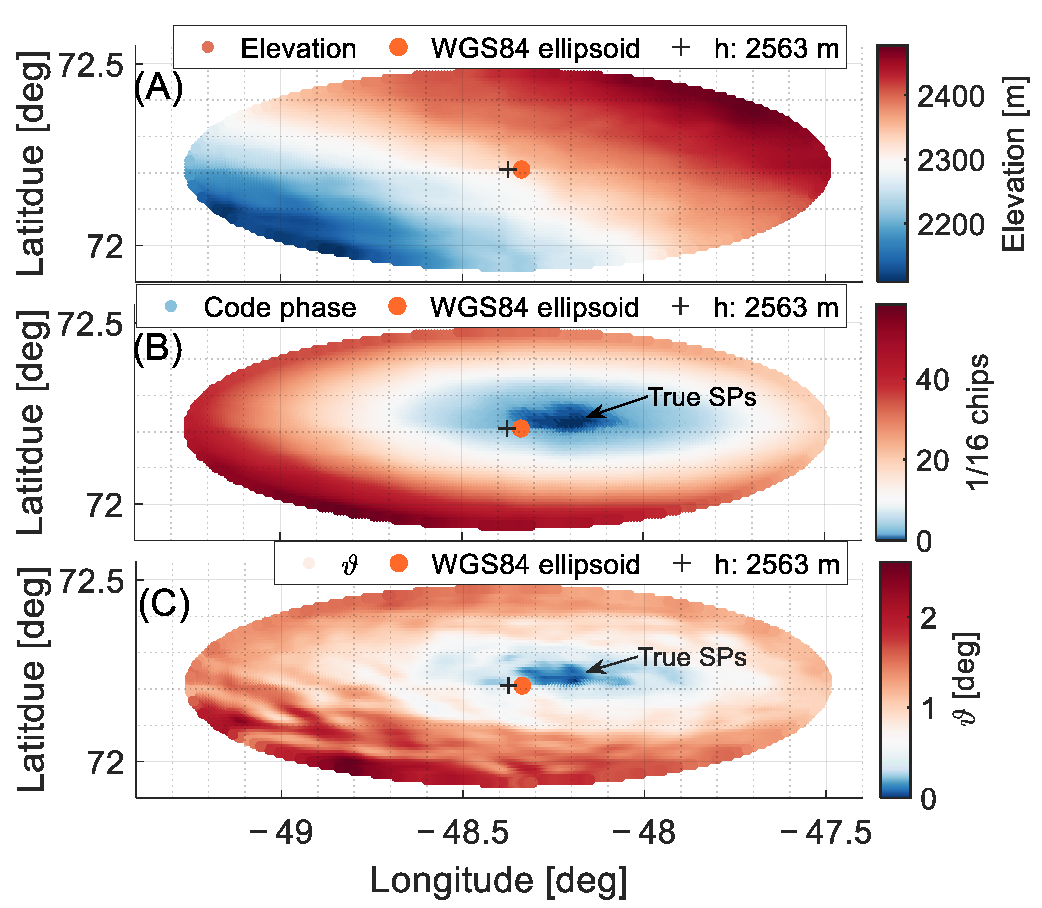
In theory, only when ϑ is equal to 0 it can be guaranteed that the signal reflected from this point is received by the receiver. However, considering the short wavelength of the L-band compared to the resolution of topography data, ϑ can be treated as a degree or probability of contribution to reflection. An instance that presents the true specular region determined according to Equations (24) and (25) and the impact of slope on the specular point location is shown in Figure 3.
It can be found that surface slopes tend to shift the specular point along the slope aspect toward uphill. This demonstrates that slopes can lead to a large source of error in the estimation of the measurement location, indirectly affecting the surface height estimation. In Figure 3, we can find that the specular region determined by the shortest length and the area according to the probability of contribution are quite close. Further investigation reveals that a slope of 0.43%, corresponding to Figure 3A, can result in a horizontal error of 5.7 km and 6.8 km in specular point estimation without and with surface height consideration, respectively.
Unexpectedly, considering surface height may increase the horizontal error over slopes due to the fact that specular point tends to move to the receiver direction as the surface slope raise. Therefore, the local area information should be introduced in the geometry computation over the tilted surface. To this end, a further altimetry algorithm as part of the Ellipsoid-based geometry computation strategy, combining the local area topography is proposed.

3.2. Geometry Computation over Slopes

The new method is based on the local area approximation. Firstly, we need to estimate the initial specular point rapidly based on the new empiric model introduced in Appendix A. Once the precise initial specular point is estimated, the local topography can be extracted based on the DEM model using the fast search method presented in Section 3.1. Then the local surface is approximated by utilizing the 2-degrees polynomial surface fitting method to obtain the topography information. However, quite complicated terrains with great abrupt elevation changes are not suitable for this method, in which the terrain information cannot be modeled well. Therefore, only relative smooth and large-scale slopes are discussed here. The model is defined as:
f p o l y ( x , y , z , m ) = p 00 + p 10 x + p 01 y + p 20 x 2 + p 11 x y + p 02 y 2 z + m
where p 00 , p 10 , p 01 , p 20 , p 11 , p 02 are the coefficients of the 2-degrees polynomial surface model, m is an assistant parameter to adjust the position of the fitted surface according to the observation. The normal vector of a point on the polynomial surface is derived as follows:
N x p = p 10 + p 11 y + 2 p 20 x
N y p = p 01 + p 11 x + 2 p 02 y
N z p = 1
where N p ( N x p , N y p , N z p ) is the normal vector on the polynomial surface. Then a set of equations similar to Equation (18) is established:
Γ p o l y = { Γ o ( x , y , z ) = 0 f p o l y ( x , y , z , m ) = 0 f i p ( x , y , z , m ) = 0 f j p ( x , y , z , m ) = 0
where f i p and f j p are the equations similar to Equations (11)–(16) restricting the two normal directions to be equal. i , j = 1 , 2 , 3 , but i j , which are selected according to the three components of the initial estimated position. Γ p o l y is the system of equations to calculate the solution X p o l y .
X p o l y = [ x , y , z , m ] T
This method takes the observed path range of reflected signals and the polynomial surface fitting of the local terrain as inputs, and finally obtains the specular point that matches the local reflection surface and the path range observation. Due to the precise initial specular point, the solution can be calculated efficiently based on the Newton–Raphson method [49].

3.3. Analysis of Errors Based on Simulations

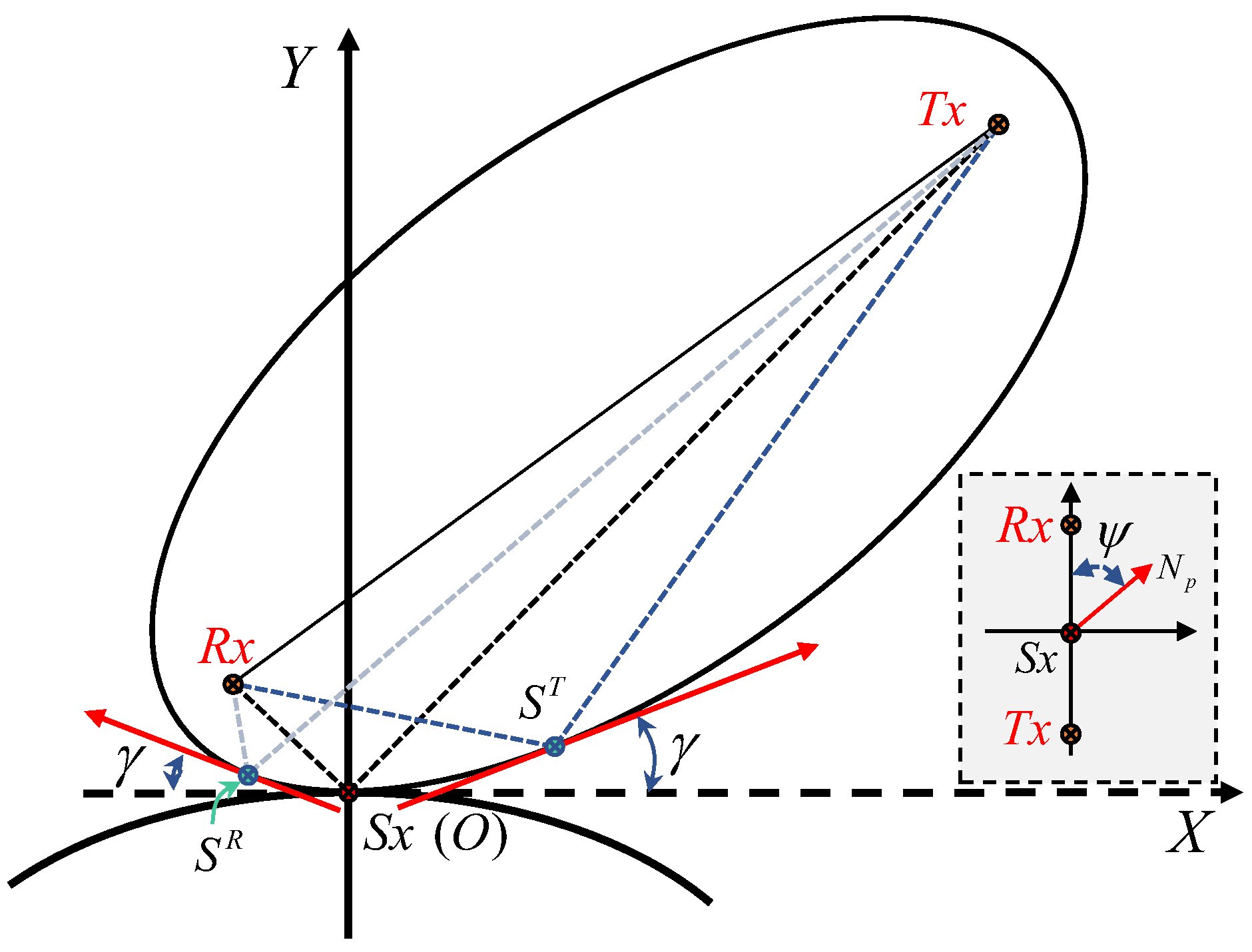
As the analysis in Section 3.1 shows, slopes can lead the specular point to a shift in the horizontal and height directions. There are two significant factors related to the errors. One is the slope angle of the reflective surface, which can affect the horizontal and vertical shifts, as γ indicated in Figure 4. The other factor is the slope aspect with respect to the scattering plane defined by the receiver, transmitter, and the specular point at the ellipsoidal surface, which is represented by ψ in the bottom-right corner in Figure 4.
The slope aspect mainly determines the shift direction of the specular point, but it still affects the magnitude of the error. Since the orbital height of the receiver is much lower than that of the transmitter, the errors in both horizontal and vertical directions in the situation where the slope aspect points to the receiver, i.e., ψ = 0 ° , are slightly larger than that when ψ = 180 ° . However, both errors reach their minimum when the slope aspect is perpendicular to the scattering plane, i.e., ψ = 90 ° . A comprehensive simulation taking into account the surface slope and three extreme situations, where normal vectors of the slopes are parallel or perpendicular to the scattering plane, is carried out. The results are presented in Figure 5.
In Figure 5 and Figure 6, geometric situations are simulated with elevation angles from 20 degrees to 70 degrees extracted from the dataset of the TDS-1 mission. In each geometry, the path range of the reflected signal is fixed and equals the path length when the specular point is on the WGS84 ellipsoidal surface. Then we change the surface slope by considering the constraint that the slope aspect parallels or is perpendicular to the scattering plane to calculate the tangent point between the observed ellipsoid and tilt reflecting surface.
As introduced in Section 2, this tangent point is the specular point at the slope when taking the surface slope and its aspect into account. Provided that the tilted surface is broad enough to maintain a fixed slope at the local reflecting area, the specular point can suffer from large shifts in horizontal and vertical directions. As presented in Figure 5, the errors increase as the surface slope angle increases and the elevation angle decreases. When the surface slope is around 0.4% at elevation angles of 20 degrees and 50 degrees, the shifts in the horizontal direction can reach 31 km and 8.3 km, and the height errors are about 140 m and 22 m, respectively. Compared with two slope aspects parallel to the scattering plane, the simulation confirms that the slope aspect toward the receiver can lead to a slightly larger error in specular point estimation than that toward the transmitter, which is more significant in the low elevation angles. In another situation where ψ = 90 ° , the offsets in both directions maintain close and minor values with an inverse trend concerning elevation angles when ψ = 0 ° or 180°. Nevertheless, it still causes a 5 km shift in the horizon at the slope of 0.4%. Almost a 17 m shift in height estimation can be found at the slope of 0.5% that commonly existed in Greenland [51].
Although this simulation assumes a flat surface and a smooth plane with an unchanged slope, it can be taken as a reference to understand the extent to which the large-scale slope affects the calculation from a perceptual aspect when the GNSS-R technique is applied to the cryosphere, e.g., Greenland and Antarctica. The reflected surfaces in Greenland and Antarctica regimes tend to be smooth and flat enhancing the reflection intensity. In addition, as demonstrated in Figure 5, lower elevation angles can exacerbate the accumulation of errors. Therefore, the surface slopes will be a complicated challenge for the GNSS-R technique focusing on grazing conditions and applied to the cryosphere [52,53]. The next section will present a detailed investigation on a single track over the Greenland surface with a typical slope based on the data from the TDS-1 mission.

4. Datasets and Results

4.1. Datasets

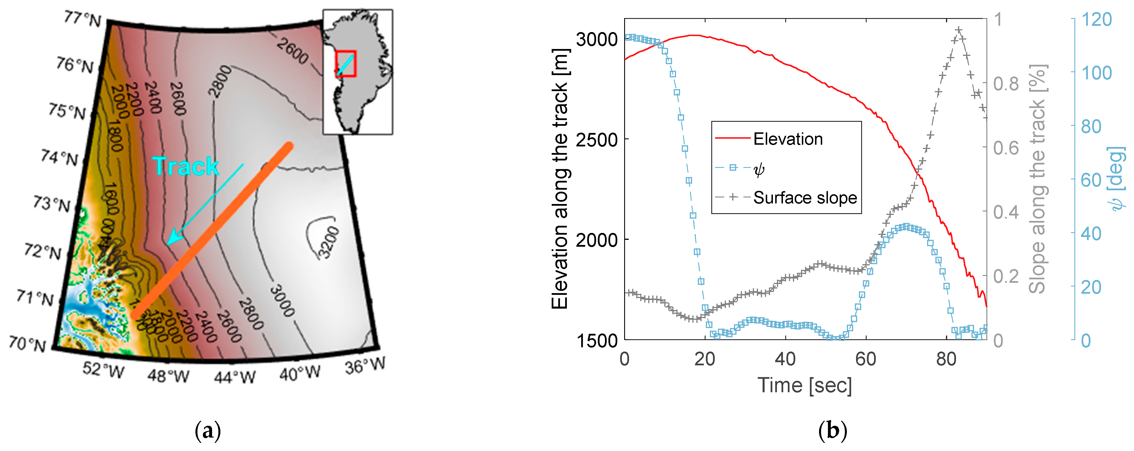
To validate the proposed method and the impact of slope on the spaceborne GNSS-R geometry computation in altimetry, a single TDS-1 track over southwest Greenland is pre-processed based on a software-defined radio GNSS receiver [54] to obtain the 1-ms waveform observations with a 1/16 chips delay resolution. The data used in this paper has been trimmed to 90-s to ensure the reflection points are located over the relatively simple terrain, avoiding the influence of complicated raised hills near the edge on the reflected signal. The footprints of the track are plotted in Figure 6a. The specular points move from the ridge of Greenland to the southwest and close to the Jakobshavn Glacier with large elevation differences from 3000 m to 1600 m, as shown in Figure 6b. The elevation angles at the specular point decrease from 57 to 52 degrees with an almost unchanged azimuth of 238 degrees. The first reflection zone derived in [3] reaches 18 km. Considering the 550 km track length on the surface, this condition is close to the modeling using a flat and tilted plane. The surface slope along the track is increasing as the specular point is approaching the edge of Greenland. The profile slopes are calculated according to the specular point locations along the track based on the TanDEM-X 90 m DEM [55], which is rising from 0% to 1%, as presented in Figure 6b.
As the analysis above, the slope aspect can disturb the offsets of the specular point in the horizontal and vertical directions. Accordingly, we also calculate the slope aspect of the neighbor regime around the specular point using a flat plane fitting method based on the TanDEM-X 90 m elevation product. Here we present the angel ψ , as introduced in Figure 4, to investigate its influence on geometry computation. As shown in Figure 6b, the angle ψ covers from 0 to 120 degrees and keeps a small difference from 20 to 55 s. This condition is favorable for the validation study as the extreme effects of the slope aspect commonly happen at ψ = 0 ° ( 180 ° ) and ψ = 90 ° .

4.2. Data Processing

As introduced above, the proposed ellipsoid-based geometry computation strategy requires the observations of path ranges of reflected signals, which assists to build the observed ellipsoid. Slightly different from the bistatic delay used in the traditional method, the observed path range of the reflected signal, i.e., | R x S x | + | T x S x | in Figure 1, consists of several steps. By considering the errors in the propagation of GNSS signals from the transmitter’s direct or indirect arrival at the receiver, we can obtain the expressions of the path ranges of direct and reflected signals in the vacuum by:
ρ R S T = ρ R T + ρ o b ρ i o n r ρ t r o r + ρ t i d e r
ρ R T = ρ g R T ρ o r b i t R T
where ρ R S T is the path range of reflected signals propagating in the vacuum from the positions of the transmitter to the receiver after the reflection from the Earth’s surface. ρ R T is the path range of direct signals propagating in the vacuum from the positions of the transmitter to the receiver. ρ o b is the observed bistatic delay containing several propagation errors. ρ i o n r , ρ t r o r , ρ t i d e r are the ionospheric, tropospheric, and tide errors, respectively. ρ g R T is the geometric range, calculated from the positions of the transmitter and receiver, of the direct signal from the transmitter to the receiver. ρ o r b i t R T is the delay error caused by the inaccurate orbit of the receiver.
From another perspective, the observed bistatic delay ρ o b r can be extracted from the time-series of the waveforms obtained from the signal cross-correlation process [36]. The waveform observation can be used to derive local path delay information with respect to the pre-defined geometry where the specular points locate at a pre-set ellipsoid height. In the implementation, the original waveforms are processed assuming that specular points are at an ellipsoid height of average elevation along the track. The delay resolution is 1/16 chips of C/A code length (~18 m) with a spread of 500 samplings centered at the 193rd sample point. The peak maximum method [56] is employed to re-track the delay point of specular reflection due to the strong power of reflection over flat and smooth ice surfaces. This method is combined with a spline interpolation to increase the sampling resolution to 1cm. Here we define the delay with respect to the predicted specular delay point (193rd for this data) extracted from the reflective waveform is δ ρ p r . With predicted bistatic delay ρ p r e inputting to the open-loop process of reflection, the observed bistatic delay ρ o b is obtained by:
ρ o b = ρ p r e + δ ρ p r δ ρ r d
where δ ρ r d is the residual delay error after the time-series fitting for delay observations extracted from the waveform of direct signals.
Accordingly, combining Equation (33), the true path range of the reflected signal propagating in the vacuum is calculated as:
ρ R S T = ρ g R T ρ o r b i t R T + ρ p r e + δ ρ p r δ ρ r d ρ i o n r ρ t r o r + ρ t i d e r
where ρ R S T = | R x S x | + | T x S x | , which is a vital input of the proposed ellipsoid-based computation strategy.
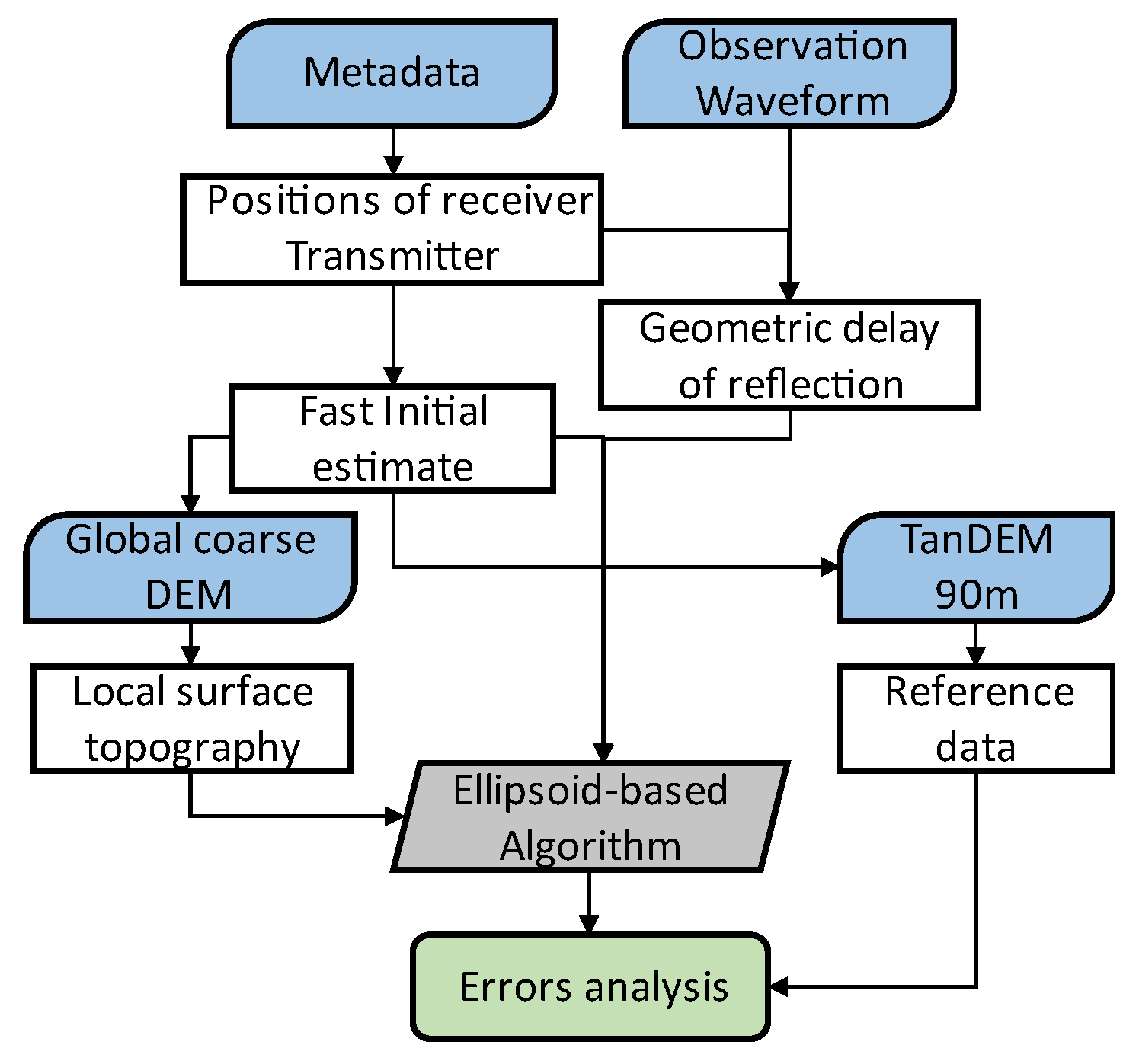
One of the significant challenges in data processing is the error corrections due to the receiving capacity of the single-frequency signal. For the ionospheric error, it varies greatly with time and space, which cannot be fully corrected currently until receiving dual-frequency GNSS signals using the ionosphere-free combination method. However, there are models to be used for partial corrections [57,58]. The tropospheric error is corrected by the hybrid UNB3 model [59] that consists of the Saastamoinen vertical propagation delay models and the Niell mapping functions, and it can be further weakened by the ray-tracer method [47]. The orbital error is corrected based on the high-resolution DEM model using a similar fitting approach in [35,36]. Here TanDEM-X 90 m [55] surface elevation model is involved as reference data and assists in providing the approximate true specular point according to the investigation in Section 3.1. The entire processing flow is given in Figure 7.
In this study, to validate the correctness of the proposed method, two surface elevation models are used. One is the global coarse DEM model used to combine the fast initial estimation method and to obtain the local topography, see Section 3.1. The other is the high (90 m) resolution of TanDEM-X DEM model, which is a relatively better model in the Greenland area to be used as reference data [60]. Three methods involved in the comparison of the altimetry over slopes are listed in Table 2.
In each method, the results are separated into two components, i.e., geolocations and heights, to evaluate the precision. These two components in the typical method (M#1) are calculated separately, which means both components are not matched when the surface height is ignored. The second method (M#2) is one of the parts of the ellipsoid-based geometry computation strategy introduced in Section 2. This method is based on observations and the assumption that the reflection point is on the ellipsoidal surface. If the precise altitude is considered, M#1 and M#2 are quite closed. Here the height of the surface is ignored in M#1 to figure out the discrepancy of the specular location in the horizon when the surface height is or is not considered.

4.3. Results and Analysis

Following the data process in Figure 7, the results are analyzed separately to investigate the slope influence on the geometry computation through both the height estimation and measurement location aspects. The reference specular points are obtained by averaging the specular regions based on the TanDEM-X 90 m elevation model as introduced in Section 3.

4.3.1. Effects of the Slope Angle

The horizontal components of each method are represented by latitudes and longitudes, and the horizontal offsets compared to the reference point are shown in Figure 8a. The vertical component represented by ellipsoidal height differs from the reference height given in Figure 8b.
As simulated in Section 3.3, slopes can lead to errors of several kilometers in a horizontal direction under the condition of the same total path range of the reflected signal. This is consistent with the results presented in Figure 8a. Horizontal errors of specular points calculated by M#1 and M#2 increase with surface slope, and both keep a similar variation trend along the receiving time. However, some asynchronous changes occur in areas where slope aspects change. Between those two methods, a small discrepancy can be found during the period between 1 to 60 s. Specifically, two dotted lines in Figure 8a are changing alternately. At the time of the 14th second, the horizontal shift of M2# exceeds that of M#1 and keeps a stable contrast, which is consistent with the variation of the slope aspect information in Figure 6b. It also shows that it is not always optimal to consider height in the geometry computation. Due to the slope effects, surface height considered in specular point estimation may lead to a more obvious shift compared to the location at the reference ellipsoid surface. This is closely related to the relative orientation between the slope and scattering plane. Nevertheless, the horizontal shift can reach 12 km when the surface slope is 0.8% and the aspect approaches 0 degrees. The maximum geolocation offset can be found at the largest slope point, resulting in an error more than 16 km. The standard deviations of the overall horizontal errors from M#1 and M#2 are 4758 m and 4801 m, respectively. For the proposed method based on the topography, the standard deviation of error is significantly improved to 367 m, as demonstrated by the purple circle and yellow cross dot at the bottom of Figure 8a. The results represented by the purple circle are the improvement on the yellow cross results by removing the coarse point in the local surface fit. The light blue line shows the precision of surface fitting, which decreases significantly when the footprint approaches the edge of Greenland. Complicated terrain at the edge of Greenland leads to a significant challenge for the GNSS-R technique. On the other hand, the proposed method still shows a decent performance even though the surface slope exceeds 0.8% and residual errors of surface fitting are larger than 200 m.
The precise positioning of the specular reflection point in the horizontal direction is required for accurate altimetry. A large slope of 1% can lead to at least a height error of 10 m under the condition of a 1 km geolocation offset. Not unexpectedly, large errors happen in the surface height retrievals, as presented in Figure 8b. The errors with respect to the reference data obtained from the three methods are represented by the red square, purple circle, and green triangle, respectively. It showed that the results of M#1 and M#2 are close, but a small difference around 0.1–0.5 m exists due to the approximate process in M#1, which is not plotted here. Since these two methods ignore the surface slope effects, the errors in height estimations gradually increase as the signals tend to keep the shortest propagation path on the slope. The errors in height retrievals from the M#1 and M#2 reach 20 m for a surface slope of 0.4% and almost 90 m for a surface slope of 0.8%. However, the proposed method maintains a stable error level along the changing slopes and aspects. Slightly large errors occur in the large slope areas. This is mainly caused by the bad delay precision extracted from the waveform observations. The accuracy of height retrievals from the proposed method reaches 5.8 m, which is greatly improved compared to the M#2 with an accuracy of 28 m.
A light blue line in Figure 8b shows the discrepancy between the proposed method and the ellipsoid-base method (M#2), which is plotted on the right axis with a variation range from 0 m at the slope-free point to 100 m at the largest slope point. It shows a similar trend, however, slightly different from the slope curve in Figure 8a. A magnified plot in Figure 8b shows that its changing rate along the time is slightly inverted to the surface slope, which is also a signal of the influence caused by the slope aspect on the height retrievals.

4.3.2. Effect of the Slope Aspect

To further investigate the influence of the slope aspect on the results in this real slope situation, a deeper simulation based on the same input geometric information of the proposed method, including the true path ranges of reflected signals and positions of the transmitter and the receiver, is conducted.
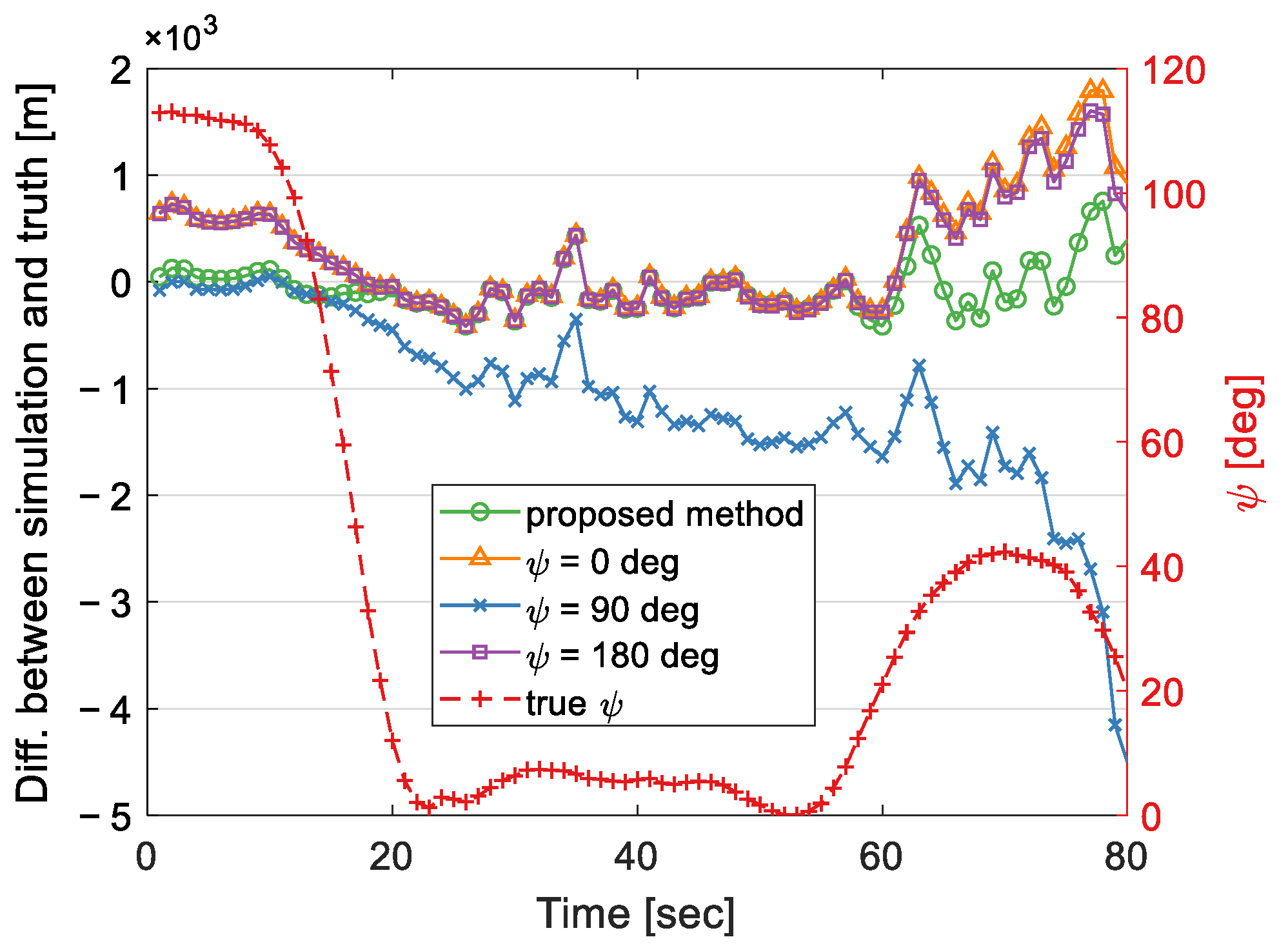
Firstly, the reliable and factual slope information extracted from the TanDEM-X 90 m model is input to simulate the same geometric condition (including slope angles and aspects), and then calculate the difference between the modeled results and reference data, which is plotted in the green circle in Figure 9. The only difference is that the local terrain is replaced by a flat plane defined by the surface slope and its aspect. The results reveal that the simulated shift is quite close to the reference data with an accuracy of 228 m, which confirms the accuracy and reliability of the simulation given in Figure 5. Besides this, three other special situations, at different angles between the slope aspect and the scattering plane ψ , are also included in the comparison. The first one assumes that the slope aspect is fixed and toward the receiver, i.e., ψ = 0 ° , and its results are shown with the orange triangle dot in Figure 9. It can be found that its modeled geolocation results are the same as the reference data during the period from the second 20 to 60 due to the true slope aspects being close to the receiver’s direction. However, discrepancies occur in two aspect changing periods starting from 20th and 60th seconds. The same result but slightly small can be obtained from the third situation where the slope aspect is toward the transmitter, i.e., ψ = 180 ° . Its results are presented with purple square dots, which is consistent with the simulation results presented in Figure 5. At ψ = 90 ° , errors increase as the slope is gradually steep except for the beginning period when the slope aspects are close to 90 degrees. These results again confirm that the slope aspect has a significant influence on the geometry computation in addition to the pure surface slope angle. In addition, it has validated the correctness and reliability of the proposed method.

5. Discussions

In the following part, several factors are discussed, including the surface fitting model, the size of the local area, and the initial coarse DEM model that is used for geoinformation extraction.

5.1. Surface Fitting Model

The GNSS-R technique cannot avoid the impact of slope due to its bistatic model with wide change ranges of elevation angles and azimuths. The new method proposed in this paper is based on the local topography information to correct the errors caused by the slope. Therefore, it is crucial to precisely extract the local topography information. The fitting model given by Equation (26) is a quadratic surface equation. In truth, to ensure the accuracy of fitting, a higher-degree surface model can be used. However, we should be careful about the variability of the high degree surface, in which the observed ellipsoid may unexpectedly converge to another point instead of the local area near the initial estimation. In addition, the higher-degree surface requires more parameters and a larger area to fit the local surface, which will increase the complexity of the calculation. In addition to the experiments in this paper, higher-degree surface models were also investigated to evaluate the performance. It turns out that in flat and smooth areas, for instance, nearby the mid-level area of Greenland, the high-degree surface model can fit the local terrain better and lead to slightly improved results. However, once the surface tends to be gradually complicated, more uncontrolled results can be found, even though an iterative fitting approach is applied. On the contrary, the quadratic surface model is more stable and performs better combining the iterative fitting approach. As a result, the quadratic surface model is recommended. Definitely, a more advanced curve surface model can further unlock the potential of this geometry computation strategy and acquire more precise results even in more complicated terrain.

5.2. Selection of Fitting Data in the Local Area

Due to the errors in the initial estimation, the size of the local area is supposed to be large enough to cover the true specular point. Taking the errors of the initial estimations and specular point shifts into account, the radius of the local topography data should reach 20 km or more, and it depends on the surface slope and elevation angles, as the simulation in Figure 5 shows. According to the grid segmentation method introduced in Section 3.1, a fast local area search can be carried out after the box numbers are determined. However, only based on the data in those selected grids, relatively large errors still occur in the steep slope and complicated regimes. The reason is that the shape of those selected grids based on the latitude-longitude-gridded elevation product is commonly a narrow rectangle in the high latitude region, while this narrow rectangular-shaped local topography is not conducive to fitting and obtaining comprehensive slope information. Points far from the true specular point can affect the surface fit even though the distance-weighted approach is introduced in the fitting. Therefore, there are two ways to reduce the impact of the local area on the surface fitting. One is to search all the selected grids terrain points centered on the initial specular point for a given radius. When a small local terrain has been determined, this step can be efficiently implemented. It reveals that circular-shape local terrain data is more favorable for fitting to extract surface information. The second approach of selecting the fitting data is based on the total path length of reflected signals. Assuming each point in the local area contributes to the observation, then the corresponding path length can be calculated and length constraint is applied to filter all the points in the selected grids. However, the second method is susceptible to complex terrain. For instance, topography with sudden localized bulges can dominate the filtered data, thus affecting the accurate fit of the local terrain. Nevertheless, both methods can significantly improve the accuracy compared to the fitting based on the original selected grid data. The first method is applied in this paper.

5.3. Selection of the Coarse DEM Model

As discussed above, a better characterization of the local terrain topography is important for the processing. From another perspective, the fundamental topography model used for extracting the local terrain is also important for this method. To improve computational efficiency, the resolution of the DEM model should be considered. It turns out that 30 arc-second resolution is enough for surface fitting based on the 20 km radius circle of terrain. In the Greenland region, the resolution is about 950 m in the longitude direction and 250 m in the latitude direction for a 30 arc-second resolution model. Further investigations reveal that a more refined DEM model data cannot lead to better results; instead, it leads to more computational time. Table 3 lists the comparison between different DEM models of Greenland, at five search radiuses r s .
The fundamental DEM model is input to provide the local geoinformation based on the quadratic surface model. Due to the characteristic of the low degree surface model, the additional detailed surface elevation data from the high-resolution DEM model will not have a significant impact on the fitting. The results of Arctic DEM models [61] with resolutions of 100, 500, and 1000 m, released by the Polar Geospatial Center, demonstrated that the high-resolution DEM model cannot improve the accuracy of the results, which means that 100 m resolution is saturated for local slope information extraction. However, results based on the 1 arc-minute resolution ice surface elevation model: ETOPO1 [62], indicate that the precision is slightly decreasing as the resolution (1800 m in the longitude and 600 m in the latitude direction) exceeds 1000 m. Therefore, a DEM model with a resolution of 1 km or 30 arc-second is recommended to be used as an initial coarse DEM model.

6. Conclusions

GNSS-R technique demonstrated a potential way to investigate the Earth’s surface with a high temporospatial resolution over the ocean and land. In this study, the effect of topography on the geometry computation of the spaceborne GNSS-R was investigated. A new geometry computation strategy based on the unique property of the ellipsoid in different situations was proposed. In addition, a fast empirical model for initial estimation was presented, which can significantly improve the GNSS-R geometry computational efficiency. To validate the method, a single track over the southwest Greenland ice surface was studied. The results confirmed that the large-scale slope can lead to significant errors of specular points in both horizontal and vertical directions when the slope and its aspect were ignored. Taking the TanDEM-X 90 m elevation model as a reference, 10 km errors in the horizontal direction and 50 m in the height direction for a slope of 0.6% at the elevation angles of 54 degrees can be found. Footprint location error has been reduced greatly from 4758 m to 367 m for the track under study.
In the GNSS-R technique, the bistatic passive model required a versatile geometry computation to accommodate scenarios with different surface heights and topographies. A high-efficient and precise geometry computation strategy for all situations are essential. An Earth ellipsoid surface-based method is not able to satisfy the requirements for different applications such as altimetry. The new approach proposed in this study shows a more prospective way to solve the geometric issues. In addition, it can be further combined with a more advanced surface approximate fitting model to increase the potential to track the footprint accurately. It can additionally feedback delay information to the onboard process of reflected signals efficiently, especially in the context of the current proposal to adopt GNSS-R technology in polar regions [52].
The correctness of simulations regarding slope influence on specular point calculation has been validated. Accordingly, more attention should be paid to the effect of the large-scale slope on grazing observations. A large source of errors caused by the prior known topography may occur and exhibit a disorganized character. Furthermore, the simulation also reveals that the partial extreme topographic slope of the ocean may also have an impact on the high-precision carrier phase altimetry in grazing angle conditions, which also needs to be further considered in the precise altimetry in the future.

Author Contributions

Conceptualization, X.H., M.S. and J.W.; methodology, M.S., M.A. and W.L.; software, M.S.; validation, R.X. and D.J.; investigation, X.W.; resources, W.L. and J.W; writing—original draft preparation, M.S. and M.A.; writing—review and editing, X.H. and J.W. All authors have read and agreed to the published version of the manuscript.

Funding

This research was funded by the Natural Science Foundation of China (Grant No. 41830110 and No. 42174018), the Fundamental Research Funds for the Central Universities (Grant No. B200203110), Postgraduate Research & Practice Innovation Program of Jiangsu Province (KYCX20_0489), and the State Scholarship Fund from Chinese Scholarship Council (No. 202006710115).

Acknowledgments

We appreciate Surrey Satellite Technologies Ltd. making their data from TechDemoSat-1 available to the public at www.merrbys.co.uk (accessed on 5 August 2021). We are also grateful to the ICE/IEEC-CSIC for making the waveform data accessible at https://www.ice.csic.es/research/gold_rtr_mining (accessed on 1 July 2021).

Conflicts of Interest

The authors declare no conflict of interest.

Appendix A

A New Empirical Model for Initialization

A fast and accurate initial input can expedite the estimation of precise specular points. Previous analyses are commonly based on the subpoint of the receiver on the Earth’s surface or the weighted distance along the vector from the receiver to the transmitter and then scaled down to the Earth’s surface to get the initial specular point [30,38], as shown in Figure A1. We can find an estimated point S on R T , and then set the subpoint, S , of S on the sphere Earth’s surface as the initial estimation of specular point. The precision of estimation obtained from this method depends on the position of S . In previous studies, S is determined approximately by the weighted distance approach, and its expression reads:
S = O S | O S | × r s p h e r e
O S = O R + η R T
where r s p h e r e is the radius of the Earth sphere, η is the weight and calculated by:
η = | R R | | T T |
where R and T are the subpoints of the receiver and transmitter in Figure A1. However, unaccepted large errors can be found in low elevation angle situations based on these approaches, which is caused by the incorrect hypothesis that the heights of the receiver and transmitter to the tangent plane at the specular point are equal to the ellipsoid height. Therefore, if the heights of the receiver and transmitter to the tangent plane at the specular point are known and the Earth is assumed spherical, this method is theoretically valid and reliable. In this work, we proposed an empirical method to determine the accuracy point S .
Figure A1. The geometry of initial specular points estimation. S is the specular point; R and T denote the receiver and transmitter; R and T are the orthographic points on the tangent plane to the sphere Earth at S ; S is the intersection of vector O S and R T .
Remotesensing 14 02105 g0a1
In Figure A1, once the vertical distances of R and T to the tangent plane are known, the intersection point S of the vector O S and the vector R T can be obtained by (A2) with a new weight calculated by:
η = | R R | | T T |
Then the initial specular point can be estimated by scaling the S to the sphere Earth surface based on Equation (A1). In this study, the radius of the sphere Earth r s p h e r e is set to the mean radius of WGS-84 ellipsoid (6378 km). After obtaining the position of S in Figure A1, we can simply transform it to the WGS84 ellipsoid surface by multiplying the transformation matrix according to the method in [25] to reduce the errors caused by the Earth’s curvature, as follows:
S e = S × M e  
M e = [ r s p h e r e r m a j o r W G S 84 0 0 0 r s p h e r e a W G S 84 0 0 0 r s p h e r e r m i n o r W G S 84 ]
where r m a j o r W G S 84 and r m i n o r W G S 84 are the semi-major axis and semi-minor axis, respectively.
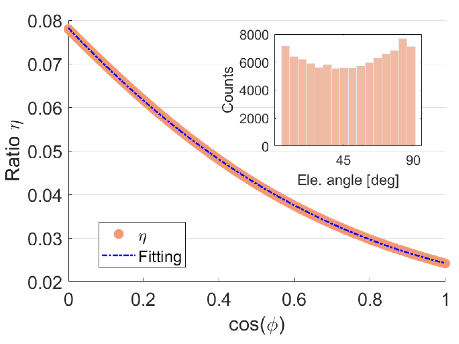
However, it is impossible to get this precise ratio η only based on the position of the receiver and transmitter. Therefore, we try to estimate it empirically. Firstly, we implement a comprehensive simulation corresponding to different orbit heights from 300 km to 1200 km. In each simulation, the geocentric angle φ , shown in Figure A1, between receiver and transmitter is calculated to figure out the relationship between φ and ratio η . Here an example corresponding to the orbit height of 500 km is shown in Figure A2.
Figure A2. The relationship between geocentric angles φ and distance ratio η . In this simulation, 100,000 events were involved, and a histogram plot of the elevation angle is shown in the top right corner.
Remotesensing 14 02105 g0a2
In Figure A2, simulations are obtained in the situation where the receiver height is 500 km and the transmitter height is 20,200 km (GPS), with an even distribution in the elevation angles. It can be found that the true ratio η demonstrates a smooth and regular trend along with the cosine value of the geocentric angle φ . Thus, here a cubic-polynomial fitting method is applied to fit the dot trend and it exhibits a decent performance. The fitting model is as follows:
η = p a η c o s ( φ ) 3 + p b η c o s ( φ ) 2 + p c η c o s ( φ ) + p d η
where p a , b , c , d η are the coefficients of the fitting model.
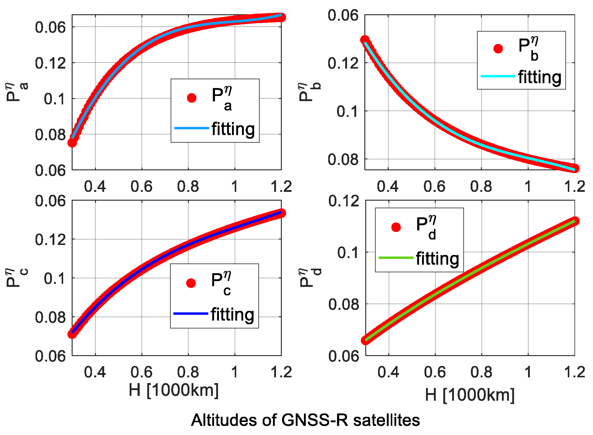
Once the curve corresponding to different orbit heights is fitted, the relatively precise ratio η can be estimated by inputting the geocentric angle φ , which is easy to calculate. According to this idea, a comprehensive simulation related to different orbit heights and geocentric angles is implemented. Based on the simulations, it finds that the coefficients along the varied orbit heights of the receiver demonstrate regular and smooth changes, as the dot presented in Figure A3.
Figure A3. Variations of coefficients in Equation (A7) versus the orbital heights of the receiver. The results are obtained by the 100,000 simulations at each orbit height situation.
Remotesensing 14 02105 g0a3
In Figure A3, the variations of coefficients in Equation (A7) along the increasing orbit heights show a monotonous trend of change. To reduce the computational overhead, a cubic-polynomial fitting method is employed to estimate the coefficients with respect to different orbit heights of receivers. The fitted model is as follows, and fitting results are given in Figure A3:
P a , b , c , d η = p 1 H H 3 + p 2 H H 2 + p 3 H H + p 4 H
where p 1 , 2 , 3 , 4 H are the coefficients of the fitting model, which are used to estimate the coefficients p a , b , c , d η in Equation (A7). Further tests reveal that the cubic-polynomial curve is not the best fit, but it is decent for the initial estimation and minimizing calculation load. The coefficients from the fits along the orbit heights are given in Table A1. To ensure the order of magnitude of the coefficient, the unit of H is 1000 km.
Table A1. Parameter fitting results of coefficients in Equation (A8) for empirical model functions.
p a , b , c , d η p 1 H p 2 H p 3 H p 4 H
p a η 0.04478−0.13250.1333−0.04484
p b η −0.084420.2599−0.28920.1341
p c η 0.03152−0.099350.1240−0.1332
p d η 0.008292−0.030640.081510.04403
Combining Equations (A1)–(A8), Table A1, and the transformed method in [25], the initial specular point can be estimated rapidly. However, we should be aware that the ratio η will also be affected by different heights of the transmitter. A height of 20,200 km is fixed in the simulation, which is slightly different from the natural orbits of GPS satellites. So, the position of the transmitter should be scaled to the fixed height before the initial estimation to weaken the relatively small orbital height influence, as follows:
T = O T | O T | × ( H T + r s p h e r e )
where T is the transmitter position, H T is the mean orbital height of the transmitter, 20,200 km for GPS satellites. r s p h e r e is the mean Earth’s radius (6378 km). Then, T is entered in Equation (A2).
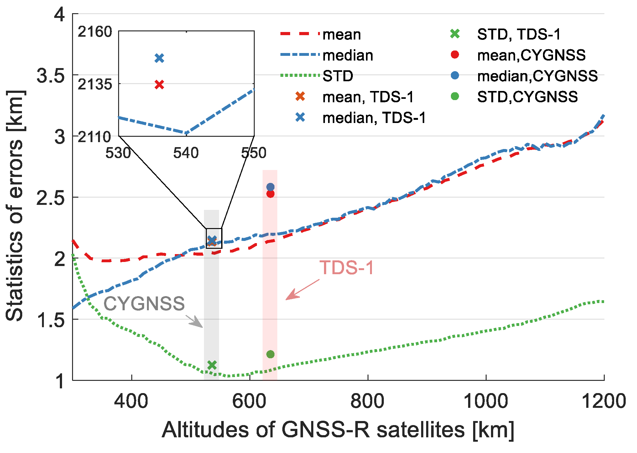
To verify this empirical method, another simulation covering the orbit height from 300 km to 1200 km was carried out, and its statistics of tridimensional errors (Euclidean distance) are presented in Figure A4.
Figure A4. Statistics of empirical specular point estimation errors corresponding to different orbit height situations. The radius of the Earth sphere is 6378 km, and the fixed height of the transmitter is 20,200 km. A quantity of 900,000 and 320,000 events (only GPS) from the TDS-1(cross dots) and CYGNSS (circular dots) satellites are also used to validate this empirical model, respectively.
Remotesensing 14 02105 g0a4
In Figure A4, the mean, median, and standard deviation (STD) of tridimensional errors are calculated. Overall, the standard deviation is almost maintained below 1.5 km, and mean and median errors are almost less than 3 km through all orbit height situations. Results from the CYGNSS and TDS-1 satellites validate this method and their error statistics are close to the simulations when the GPS satellite is the transmitter, which turns out that the empirical model can implement a fast and precise initial geometry calculation. Similarly, the coefficients of the fitting model (Equation (A8)) for Glonass, Galileo, and Beidou (MEO) systems are given in the following tables.
Table A2. Coefficients of the fitting model for Glonass system (Mean orbital height: 19,000 km).
p a , b , c , d η p 1 H p 2 H p 3 H p 4 H
p a η 0.0695−0.19870.1874−0.05558
p b η −0.13160.387−0.39580.1581
p c η 0.05733−0.16880.1838−0.1515
p d η 0.005163−0.022940.077670.049
Table A3. Coefficients of the fitting model for Galileo system (Mean orbital height: 23,220 km).
p a , b , c , d η p 1 H p 2 H p 3 H p 4 H
p a η 0.05364−0.15560.1507−0.04809
p b η −0.097380.2902−0.30430.1306
p c η 0.03784−0.11250.125−0.1199
p d η 0.006253−0.024760.072240.03729
Table A4. Coefficients of the fitting model for Beidou system (Mean orbital height (MEO): 21,550 km).
p a , b , c , d η p 1 H p 2 H p 3 H p 4 H
p a η 0.05879−0.16980.1631−0.05077
p b η −0.10850.322−0.3350.1403
p c η 0.04405−0.13060.1443−0.1308
p d η 0.005997−0.024470.074560.04127
For different orbital height systems, dedicated coefficients for Glonass, Galileo, and Beidou (MEO) systems can achieve a similar precision (within 1.5 km) as the GPS system shown in Figure A4 in the fastest way.

References

  1. Zavorotny, V.U.; Gleason, S.; Cardellach, E.; Camps, A. Tutorial on remote sensing using GNSS bistatic radar of opportunity. IEEE Geosci. Remote Sens. Mag. 2014, 2, 8–45. [Google Scholar] [CrossRef] [Green Version]
  2. Li, W.; Cardellach, E.; Fabra, F.; Ribo, S.; Rius, A. Assessment of Spaceborne GNSS-R Ocean Altimetry Performance Using CYGNSS Mission Raw Data. IEEE Trans. Geosci. Remote Sens. 2020, 58, 238–250. [Google Scholar] [CrossRef]
  3. Hajj, G.A.; Zuffada, C. Theoretical description of a bistatic system for ocean altimetry using the GPS signal. Radio Sci. 2003, 38, 10-1–10-19. [Google Scholar] [CrossRef]
  4. Mashburn, J.; Axelrad, P.; Lowe, S.T.; Larson, K.M. Global Ocean Altimetry with GNSS Reflections from TechDemoSat-1. IEEE Trans. Geosci. Remote Sens. 2018, 56, 4088–4097. [Google Scholar] [CrossRef]
  5. Huang, F.; Garrison, J.L.; Rodriguez-Alvarez, N.; O’Brien, A.J.; Schoenfeldt, K.M.; Ho, S.C.; Zhang, H. Sequential processing of GNSS-R delay-doppler maps to estimate the ocean surface wind field. IEEE Trans. Geosci. Remote Sens. 2019, 57, 10202–10217. [Google Scholar] [CrossRef]
  6. Katzberg, S.J.; Dunion, J.; Ganoe, G.G. The use of reflected GPS signals to retrieve ocean surface wind speeds in tropical cyclones. Radio Sci. 2013, 48, 359–370. [Google Scholar] [CrossRef]
  7. Asgarimehr, M.; Wickert, J.; Reich, S. TDS-1 GNSS Reflectometry: Development and Validation of Forward Scattering Winds. IEEE J. Sel. Top. Appl. Earth Obs. Remote Sens. 2018, 11, 4534–4541. [Google Scholar] [CrossRef]
  8. Strandberg, J.; Hobiger, T.; Haas, R. Coastal Sea Ice Detection Using Ground-Based GNSS-R. IEEE Geosci. Remote Sens. Lett. 2017, 14, 1552–1556. [Google Scholar] [CrossRef]
  9. Li, W.; Cardellach, E.; Fabra, F.; Ribó, S.; Rius, A.; Weiqiang, L.; Cardellach, E.; Fabra, F.; Ribó, S.; Rius, A.; et al. Measuring Greenland Ice Sheet Melt Using Spaceborne GNSS Reflectometry From TechDemoSat-1. Geophys. Res. Lett. 2020, 47, e2019GL086477. [Google Scholar] [CrossRef]
  10. Camps, A.; Park, H.; Pablos, M.; Foti, G.; Gommenginger, C.P.; Liu, P.W.; Judge, J. Sensitivity of GNSS-R Spaceborne Observations to Soil Moisture and Vegetation. IEEE J. Sel. Top. Appl. Earth Obs. Remote Sens. 2016, 9, 4730–4742. [Google Scholar] [CrossRef] [Green Version]
  11. Al-Khaldi, M.M.; Johnson, J.T.; O’Brien, A.J.; Balenzano, A.; Mattia, F. Time-Series Retrieval of Soil Moisture Using CYGNSS. IEEE Trans. Geosci. Remote Sens. 2019, 57, 4322–4331. [Google Scholar] [CrossRef]
  12. Carreno-Luengo, H.; Luzi, G.; Crosetto, M. Above-ground biomass retrieval over tropical forests: A novel GNSS-R approach with CYGNSS. Remote Sens. 2020, 12, 1368. [Google Scholar] [CrossRef]
  13. Asgarimehr, M.; Hoseini, M.; Semmling, M.; Ramatschi, M.; Camps, A.; Nahavandchi, H.; Haas, R.; Wickert, J. Remote Sensing of Precipitation Using Reflected GNSS Signals: Response Analysis of Polarimetric Observations. IEEE Trans. Geosci. Remote Sens. 2021, 60, 1–12. [Google Scholar] [CrossRef]
  14. Asgarimehr, M.; Zavorotny, V.; Wickert, J.; Reich, S. Can GNSS Reflectometry Detect Precipitation Over Oceans? Geophys. Res. Lett. 2018, 45, 12585–12592. [Google Scholar] [CrossRef] [Green Version]
  15. Martín-Neira, M.; Martin-Neira, M. A passive reflectometry and interferometry system (PARIS): Application to ocean altimetry. ESA J. 1993, 17, 331–355. [Google Scholar]
  16. Rodriguez-Alvarez, N.; Camps, A.; Vall-llossera, M.; Bosch-Lluis, X.; Monerris, A.; Ramos-Perez, I.; Valencia, E.; Marchan-Hernandez, J.F.; Martinez-Fernandez, J.; Baroncini-Turricchia, G.; et al. Land Geophysical Parameters Retrieval Using the Interference Pattern GNSS-R Technique. IEEE Trans. Geosci. Remote Sens. 2011, 49, 71–84. [Google Scholar] [CrossRef]
  17. Cardellach, E.; Fabra, F.; Nogués-Correig, O.; Oliveras, S.; Ribó, S.; Rius, A. GNSS-R ground-based and airborne campaigns for ocean, land, ice, and snow techniques: Application to the GOLD-RTR data sets. Radio Sci. 2011, 46, 1–16. [Google Scholar] [CrossRef] [Green Version]
  18. Mashburn, J.; Axelrad, P.; Lowe, S.T.; Larson, K.M.; Lowe, S.T.; Larson, K.M. An Assessment of the Precision and Accuracy of Altimetry Retrievals for a Monterey Bay GNSS-R Experiment. IEEE J. Sel. Top. Appl. Earth Obs. Remote Sens. 2016, 9, 4660–4668. [Google Scholar] [CrossRef]
  19. Semmling, A.M.; Beckheinrich, J.; Wickert, J.; Beyerle, G.; Schön, S.; Fabra, F.; Pflug, H.; He, K.; Schwabe, J.; Scheinert, M. Sea surface topography retrieved from GNSS reflectometry phase data of the GEOHALO flight mission. Geophys. Res. Lett. 2014, 41, 954–960. [Google Scholar] [CrossRef] [Green Version]
  20. Cardellach, E.; Li, W.; Rius, A.; Semmling, M.; Wickert, J.; Zus, F.; Ruf, C.S.; Buontempo, C. First Precise Spaceborne Sea Surface Altimetry with GNSS Reflected Signals. IEEE J. Sel. Top. Appl. Earth Obs. Remote Sens. 2020, 13, 102–112. [Google Scholar] [CrossRef]
  21. Clarizia, M.P.; Ruf, C.; Cipollini, P.; Zuffada, C. First spaceborne observation of sea surface height using GPS-Reflectometry. Geophys. Res. Lett. 2016, 43, 767–774. [Google Scholar] [CrossRef] [Green Version]
  22. Gleason, S.; O’Brien, A.; Russel, A.; Al-Khaldi, M.M.; Johnson, J.T. Geolocation, calibration and surface resolution of CYGNSS GNSS-R land observations. Remote Sens. 2020, 12, 1317. [Google Scholar] [CrossRef] [Green Version]
  23. Southwell, B.J.; Dempster, A.G. A New Approach to Determine the Specular Point of Forward Reflected GNSS Signals. IEEE J. Sel. Top. Appl. Earth Obs. Remote Sens. 2018, 11, 639–646. [Google Scholar] [CrossRef]
  24. Gleason, S. A Real-Time On-Orbit Signal Tracking Algorithm for GNSS Surface Observations. Remote Sens. 2019, 11, 1858. [Google Scholar] [CrossRef] [Green Version]
  25. Jales, P. Spaceborne Receiver Design for Scatterometric GNSS Reflectometry. Ph.D. Thesis, University of Surrey, Guildford, UK, 2012. [Google Scholar]
  26. Gleason, S.; Gebre-Egziabher, D.; Egziabher, D.G.; Gleason, S. GNSS Applications and Methods; Balint, G., Antala, B., Carty, C., Mabieme, J.-M.A., Amar, I.B., Kaplanova, A., Eds.; Artech House: Norwood, MA, USA, 2009; ISBN 1596933305. [Google Scholar]
  27. Roussel, N.; Frappart, F.; Ramillien, G.; Darrozes, J.; Desjardins, C.; Gegout, P.; Pérosanz, F.; Biancale, R. Simulations of direct and reflected wave trajectories for ground-based GNSS-R experiments. Geosci. Model Dev. 2014, 7, 2261–2279. [Google Scholar] [CrossRef] [Green Version]
  28. Semmling, A.M.; Schmidt, T.; Wickert, J.; Schn, S.; Fabra, F.; Cardellach, E.; Rius, A.; Schön, S.; Fabra, F.; Cardellach, E.; et al. On the retrieval of the specular reflection in GNSS carrier observations for ocean altimetry: Reflection retrieval for ocean altimetry. Radio Sci. 2012, 47, 1–13. [Google Scholar] [CrossRef]
  29. Semmling, A.M.; Leister, V.; Saynisch, J.; Zus, F.; Heise, S.; Wickert, J. A Phase-Altimetric Simulator: Studying the Sensitivity of Earth-Reflected GNSS Signals to Ocean Topography. IEEE Trans. Geosci. Remote Sens. 2016, 54, 6791–6802. [Google Scholar] [CrossRef]
  30. Wu, S.-C.; Meehan, T.; Young, L.; Wu, S.-C.; Mcchan, T. The Potential Use of GPS Signals as Ocean Altimetry Observables. In Proceedings of the 1997 National Technical Meeting of the Institute of Navigation, Santa Monica, CA, USA, 14 January 1997; pp. 543–550. [Google Scholar]
  31. Wu, F.; Zheng, W.; Li, Z.; Liu, Z. Improving the GNSS-R Specular Reflection Point Positioning Accuracy Using the Gravity Field Normal Projection Reflection Reference Surface Combination Correction Method. Remote Sens. 2018, 11, 33. [Google Scholar] [CrossRef] [Green Version]
  32. Gleason, S.; Ruf, C.S.; Orbrien, A.J.; McKague, D.S. The CYGNSS Level 1 Calibration Algorithm and Error Analysis Based on On-Orbit Measurements. IEEE J. Sel. Top. Appl. Earth Obs. Remote Sens. 2019, 12, 37–49. [Google Scholar] [CrossRef]
  33. Rius, A.; Cardellach, E.; Martín-Neira, M. Altimetric analysis of the sea-surface GPS-reflected signals. IEEE Trans. Geosci. Remote Sens. 2010, 48, 2119–2127. [Google Scholar] [CrossRef]
  34. Li, W.; Cardellach, E.; Fabra, F.; Ribó, S.; Rius, A.; Weiqiang, L.; Cardellach, E.; Fabra, F.; Ribó, S.; Rius, A.; et al. Lake Level and Surface Topography Measured With Spaceborne GNSS-Reflectometry From CYGNSS Mission: Example for the Lake Qinghai. Geophys. Res. Lett. 2018, 45, 13332–13341. [Google Scholar] [CrossRef]
  35. Li, W.; Cardellach, E.; Fabra, F.; Rius, A.; Ribó, S.; Martín-Neira, M.; Weiqiang, L.; Cardellach, E.; Fabra, F.; Rius, A.; et al. First spaceborne phase altimetry over sea ice using TechDemoSat-1 GNSS-R signals. Geophys. Res. Lett. 2017, 44, 8369–8376. [Google Scholar] [CrossRef]
  36. Song, M.; He, X.; Wang, X.; Jia, D.; Xiao, R.; Shi, H.; Wu, Y. Study on the Exploration of Spaceborne GNSS-R Raw Data Focusing on Altimetry. IEEE J. Sel. Top. Appl. Earth Obs. Remote Sens. 2020, 13, 6142–6154. [Google Scholar] [CrossRef]
  37. Nguyen, V.A.; Nogués-Correig, O.; Yuasa, T.; Masters, D.; Irisov, V. Initial GNSS Phase Altimetry Measurements From the Spire Satellite Constellation. Geophys. Res. Lett. 2020, 47, e2020GL088308. [Google Scholar] [CrossRef]
  38. Yu, K.; Rizos, C.; Dempster, A.G. GNSS-based model-free sea surface height estimation in unknown sea state scenarios. IEEE J. Sel. Top. Appl. Earth Obs. Remote Sens. 2014, 7, 1424–1435. [Google Scholar] [CrossRef]
  39. Hu, C.; Benson, C.; Rizos, C.; Qiao, L. Single-Pass Sub-Meter Space-Based GNSS-R Ice Altimetry: Results From TDS-1. IEEE J. Sel. Top. Appl. Earth Obs. Remote Sens. 2017, 10, 3782–3788. [Google Scholar] [CrossRef]
  40. Sandwell, D.T.; Smith, W.H.F. Slope correction for ocean radar altimetry. J. Geod. 2014, 88, 765–771. [Google Scholar] [CrossRef]
  41. Carreno-Luengo, H.; Luzi, G.; Crosetto, M. First Evaluation of Topography on GNSS-R: An Empirical Study Based on a Digital Elevation Model. Remote Sens. 2019, 11, 2556. [Google Scholar] [CrossRef] [Green Version]
  42. Dente, L.; Guerriero, L.; Comite, D.; Pierdicca, N. Space-Borne GNSS-R Signal over a Complex Topography: Modeling and Validation. IEEE J. Sel. Top. Appl. Earth Obs. Remote Sens. 2020, 13, 1218–1233. [Google Scholar] [CrossRef]
  43. Cartwright, J.; Banks, C.J.; Srokosz, M. Improved GNSS-R bi-static altimetry and independent digital elevation models of Greenland and Antarctica from TechDemoSat-1. Cryosphere 2020, 14, 1909–1917. [Google Scholar] [CrossRef]
  44. Cartwright, J.; Clarizia, M.P.; Cipollini, P.; Banks, C.J.; Srokosz, M. Independent DEM of Antarctica Using GNSS-R Data From TechDemoSat-1. Geophys. Res. Lett. 2018, 45, 6117–6123. [Google Scholar] [CrossRef]
  45. Nilsson, J.; Gardner, A.; Sørensen, L.S.; Forsberg, R. Improved retrieval of land ice topography from CryoSat-2 data and its impact for volume-change estimation of the Greenland Ice Sheet. Cryosphere 2016, 10, 2953–2969. [Google Scholar] [CrossRef] [Green Version]
  46. Chen, G.; Zhang, S.; Liang, S.; Zhu, J. Elevation and Volume Changes in Greenland Ice Sheet From 2010 to 2019 Derived From Altimetry Data. Front. Earth Sci. 2021, 9, 362. [Google Scholar] [CrossRef]
  47. Zus, F.; Bender, M.; Deng, Z.; Dick, G.; Heise, S.; Shang-Guan, M.; Wickert, J. A methodology to compute GPS slant total delays in a numerical weather model. Radio Sci. 2012, 47, 1–15. [Google Scholar] [CrossRef] [Green Version]
  48. CYGNSS Level 1 Science Data Record Version 3.0|PO.DAAC/JPL/NASA. Available online: https://podaac.jpl.nasa.gov/dataset/CYGNSS_L1_V3.0 (accessed on 7 March 2022).
  49. Jorge, N.; Stephen, J. Numerical Optimization; USA (TB/HAM): Waltham, MA, USA, 2006; ISBN 978-0-387-30303-1. [Google Scholar]
  50. Zavorotny, V.U.; Voronovich, A.G. Scattering of GPS signals from the ocean with wind remote sensing application. IEEE Trans. Geosci. Remote Sens. 2000, 38, 951–964. [Google Scholar] [CrossRef] [Green Version]
  51. Schaffer, J.; Timmermann, R.; Arndt, J.; Steinhage, D. RTopo-2: A global dataset of ice sheet topography, cavity geometry and ocean bathymetry to study ice-ocean interaction in Northeast Greenland. In Proceedings of the REKLIM Conference “Our Climate—Our Future”, Berlin, Germany, 6–9 October 2014. [Google Scholar]
  52. Cardellach, E.; Wickert, J.; Baggen, R.; Benito, J.; Camps, A.; Catarino, N.; Chapron, B.; Dielacher, A.; Fabra, F.; Flato, G.; et al. GNSS Transpolar Earth Reflectometry exploriNg System (G-TERN): Mission Concept. IEEE Access 2018, 6, 13980–14018. [Google Scholar] [CrossRef]
  53. Wickert, J.; Cardellach, E.; Martin-Neira, M.; Bandeiras, J.; Bertino, L.; Andersen, O.B.; Camps, A.; Catarino, N.; Chapron, B.; Fabra, F.; et al. GEROS-ISS: GNSS REflectometry, Radio Occultation, and Scatterometry Onboard the International Space Station. IEEE J. Sel. Top. Appl. Earth Obs. Remote Sens. 2016, 9, 4552–4581. [Google Scholar] [CrossRef] [Green Version]
  54. Li, W.; Cardellach, E.; Ribó, S.; Oliveras, S.; Rius, A. Exploration of Multi-Mission Spaceborne GNSS-R Raw IF Data Sets: Processing, Data Products and Potential Applications. Remote Sens. 2022, 14, 1344. [Google Scholar] [CrossRef]
  55. Available online: https://download.geoservice.dlr.de/TDM90 (accessed on 10 September 2021).
  56. Martín-Neira, M.; Caparrini, M.; Font-Rossello, J.; Lannelongue, S.; Vallmitjana, C.S.; Martm-Neira, M.; Caparrini, M.; Font-Rossello, J.; Lannelongue, S.; Vallmitjana, C.S. The paris concept: An experimental demonstration of sea surface altimetry using gps reflected signals. IEEE Trans. Geosci. Remote Sens. 2001, 39, 142–150. [Google Scholar] [CrossRef] [Green Version]
  57. Klobuchar, J.A. Ionospheric Time-Delay Algorithm for Single-Frequency GPS Users. IEEE Trans. Aerosp. Electron. Syst. 1987, AES-23, 325–331. [Google Scholar] [CrossRef]
  58. Orús, R.; Hernández-Pajares, M.; Juan, J.M.; Sanz, J. Improvement of global ionospheric VTEC maps by using kriging interpolation technique. J. Atmos. Sol.-Terr. Phys. 2005, 67, 1598–1609. [Google Scholar] [CrossRef]
  59. Leandro, R.; Santos, M.; Langley, R.B. UNB Neutral Atmosphere Models: Development and Performance. In Proceedings of the 2006 National Technical Meeting of The Institute of Navigation, Monterey, CA, USA, 18–20 January 2006; pp. 564–573. [Google Scholar]
  60. Xing, Z.; Chi, Z.; Yang, Y.; Chen, S.; Huang, H.; Cheng, X.; Hui, F. Accuracy evaluation of four greenland digital elevation models (Dems) and assessment of river network extraction. Remote Sens. 2020, 12, 3429. [Google Scholar] [CrossRef]
  61. Porter, C.; Morin, P.; Howat, I.; Noh, M.-J.; Bates, B.; Peterman, K.; Keesey, S.; Schlenk, M.; Gardiner, J.; Tomko, K.; et al. ArcticDEM 2018, Harvard Dataverse, V1. Available online: https://doi.org/10.7910/DVN/OHHUKH (accessed on 1 October 2021).
  62. Amante, C.; Eakins, B.W. ETOPO1 1 arc-minute global relief model: Procedures, data sources and analysis. NOAA technical memorandum NESDIS NGDC-24. Natl. Geophys. Data Cent. NOAA 2009, 10, V5C8276M. [Google Scholar]
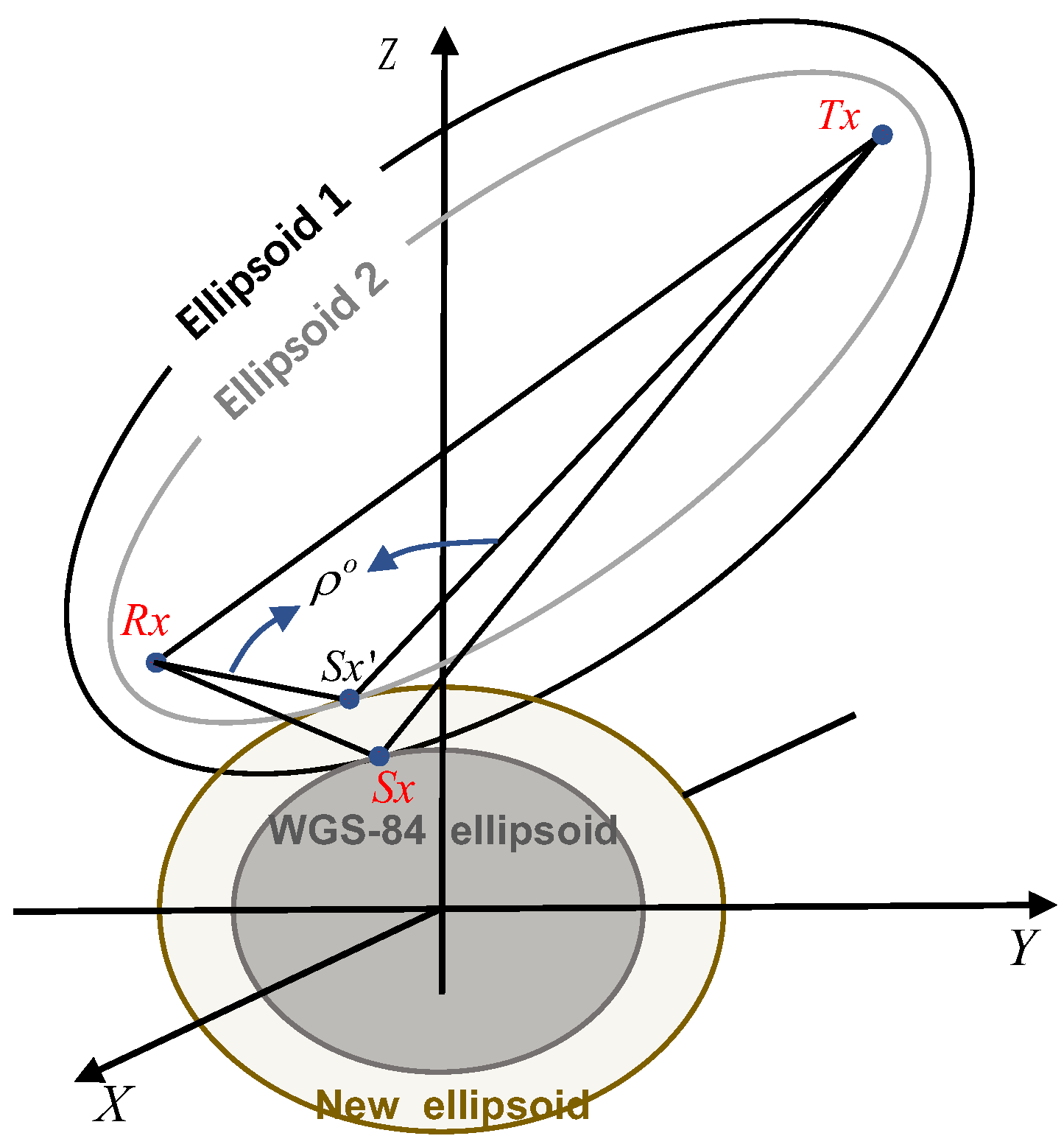
Figure 1. Schematic diagram of the ellipsoid-based geometry computation method. The transmitter ( T x ), specular point ( S x ) on WGS84 ellipsoid, and receiver ( R x ) are in the same plane, S x is the specular point corresponding to the path range of reflected signal ρ o , with a height of h on the new ellipsoid considering the curvature of the Earth.
Remotesensing 14 02105 g001
Figure 2. Quick search of local topography data based on global DEM data by reconstructing subseries boxes.
Remotesensing 14 02105 g002
Figure 3. Analysis of the specular point over the slope. The topography data is extracted from RTopo-2 [51] and centered to the specular point at the WGS84 ellipsoid surface, with a radius of 20 km. Above panel (A) presents the local topography with a slope of 0.43%. The middle panel (B) shows the relative TPL (normalized to the chip length of the C/A code). The probability of contributing to the receiver represented by ϑ is shown in (C). Black cross and brick red dots in each plot are the results calculated by specular point algorithms without and with considering the mean surface height of the local area, respectively.
Remotesensing 14 02105 g003
Figure 4. The impact of the surface slope angle, γ , (Note: γ is not in the scattering plane) and aspect on the specular points under the condition when the path range of reflected signals is determined. ψ denotes the relative relationship between the slope aspect, N p , and scattering plane. Alternatively, N p is the projection of the normal vector of the reflected surface on the plane that is tangential to the ellipsoid at the specular point S x . ψ is the angle between N p and the projection of the reflected vector (from the specular point to the receiver) on the same tangent plane at S x .
Remotesensing 14 02105 g004
Figure 5. The errors of specular points correspond to different surface slopes and aspects. Horizontal shifts (a) and height shifts (b) of specular points versus the surface slopes in three slope aspect situations corresponding to the same path range of reflected signal from the ellipsoidal surface.
Remotesensing 14 02105 g005
Figure 6. (a) Locations of the track over the DEM background in Greenland. (b) Elevations, surface slopes, and aspects at specular points. Those data are calculated based on the TanDEM-X 90 m elevation model.
Remotesensing 14 02105 g006
Figure 7. Workflow of data processing.
Remotesensing 14 02105 g007
Figure 8. Comparisons of the results in horizontal (a) and vertical (b) directions obtained from the three methods.
Remotesensing 14 02105 g008
Figure 9. The difference between the measured results and corresponding simulation with the same slope under the different slope aspects.
Remotesensing 14 02105 g009
Table 1. Comparisons of the specular point calculation performance among the ellipsoid-based geometry computation strategy (S#1), Minimum Propagation Length iterative method (S#2), and the new empirical initial estimation method presented in Appendix A (S#3). A simplified method (S#4) with only one iteration, based on S#1, is also added in the last row.
MethodsTime(s)5° < θ < 30°θ > 30°
IterationsTPL (m)SPs (m)IterationsTPL (m)SPs (m)
S#131.652.77<1 × 10⁻⁷ m<1 × 10⁻⁷ m2.72<1 × 10⁻⁷ m<1 × 10⁻⁷ m
S#276.93282.033.936059.5929.154.712227.61
S#31.53 1.022392.05 3.891811.24
S#413.2010.924.1313.632.51
Table 2. Details of methods in the comparison.
No.Method DescriptionHorizontal/GeolocationVertical/Height
M#1Typical method with equation given in Equations (1) and (2) [15,34]Specular points at WGS84 ellipsoidCalculated by Equations (1) and (2)
M#2Ellipsoid-based method given in Section 2Specular points considered Earth curvature and heightDerived from specular points
M#3Ellipsoid-based method with slope considered given in Section 3Specular points considered local topographyDerived from specular points
Table 3. Comparison of the effect of different resolutions of DEM on the results.
TopographyResolution r s = 20   km r s = 25   km r s = 30   km r s = 35   km r s = 40   km
RTopo-2.0.130 arc-
second
1845 m466 m367 m512 m642 m
ArcticDEM 100 m1024 m443 m386 m496 m607 m
ArcticDEM 500 m1022 m434 m382 m494 m606 m
ArcticDEM 1000 m1025 m413 m372 m493 m603 m
ETOPO11 arc-minute1358 m577 m513 m577 m738 m
Publisher’s Note: MDPI stays neutral with regard to jurisdictional claims in published maps and institutional affiliations.