Abstract
At the present time, most of existing security systems only detect and track targets in line-of-sight (LOS). However, in practice, the locations of targets are often out of the line of sight. This article focuses on the non-line-of-sight (NLOS) moving target detection with low-power transmission signals by reflection. There are two key problems, the weak target echo signal and the multipath effect. In terms of the issues, this paper constructs the echo signal model of the NLOS target. On the basis of the echo model, the detection method of NLOS moving target based on millimeter-wave radar comes up, which is of great theoretical value and important practical significance for indoor security. This paper innovatively applies the polynomial fitting method to suppress static noise and range gating method to suppress noise from other range gates. Then, the location and velocity of the target are estimated by two-dimensional fast Fourier transform (FFT) and the multiple signal classification (MUSIC) method. Furthermore, in order to verify the accuracy of the NLOS target echo signal model proposed in this paper, we respectively simulated two important parts of the signal in the model, the target echo signal and the direct backscattered signal of the intermediate interface, both of which are multipath signals. We counted the echo path length distribution in these two parts, and applied the NLOS target detection method to process them respectively. In addition, we also simulated the NLOS target echo signal and obtained actual data in the actual scene, and processed both the simulated data and the actual data. Comparing the results of target detection with and without denoising methods, the effectiveness of the two denoising methods proposed in this paper is verified.
1. Introduction
In modern society, safety accidents such as burglary and malicious attacks still occur all over the world. Consequently, social public safety has been attracted great attention from the public. In recent years, with the advancement of technology, the security system has also been developed rapidly. At present, most security systems use cameras, infrared devices or radars to identify and detect targets. Millimeter-wave radar has been widely used in security systems [1,2,3,4] recently due to its numerous advantages, such as strong penetrating power and ability to work around the clock. Compared with other sensors, millimeter-wave radar has many advantages. In addition, in recent years, it has also been used in 5G wireless communication [5], autonomous driving [6,7], and security inspection systems [8,9]. It can work through rain, snow and fog and is immune to weather, climate and light. Additionally, its high operating frequency makes it possible to obtain a larger bandwidth and higher range resolution. Moreover, the millimeter-wave radar works in a low operating voltage and small power and is small and light, easy to install and low in cost [10]. Due to these advantages, the application research of millimeter-wave radar in the security field is of far-reaching significance. Nowadays, most of the existing security systems can only detect targets within the line of sight. However, in practice, targets are usually hidden from sight and cannot be directly observed. Therefore, NLOS target detection technology based on millimeter-wave radar has become one of the current research hotspots. This technology is expected to provide a new information support approach for indoor security applications, which has very important theoretical value and practical significance.
The NLOS region refers to the area where targets cannot be directly observed due to occlusion. In other words, the transmitted signal of the radar cannot directly reach the target. It can reach the target by penetrating obstacles or reflection and scattering. According to the way the transmitted signal reaches the target object, the NLOS target detection technology can be divided into two classifications, based on penetration and based on reflection. For indoor security, most of the current research of NLOS target detection radars focuses on technology based on penetration, such as through-wall radars [11,12,13].
Based on the principle of the reflection of electromagnetic waves, the through-wall detection radar detects various micro-movements caused by the human body’s breathing, heartbeat, and body movement through the backscattered echo of the human target behind the wall and other obstacles to identify whether there is life. According to the system conditions, the position and speed of the target can be further estimated. Foreign research institutions have made important progress in the model of through-wall radar systems, signal processing technology, and have developed a variety of through-wall radar prototypes and experimental systems. Domestic research in the field of through-wall detection technology started relatively late but has developed rapidly in recent years. There are more and more units engaged in the research of through-wall radar [14,15,16,17].
In recent decades, researchers have made lot of efforts to detect targets behind walls, especially human targets. In 2011, Lu Biying and others at the National University of Defense Technology applied the Back Projection (BP) method and coherent change detection (CCD) technology to the stepped frequency continuous wave system through-wall imaging radar to image the human moving target behind the wall in two dimensions [18]. In 2012, Jin Liangnian of Xidian University and others proposed a coherent coefficient weighted robust Capon beamforming algorithm, which obtained better imaging results than BP. They also compared the imaging performance of multiple array forms, proving that the MIMO array can achieve better imaging results with the same number of elements [19]. In order to further improve the imaging performance of the target behind the wall with the limited bandwidth and aperture, researchers from Guilin University of Electronic Technology and Nanjing University of Science and Technology have also carried out research on this since 2017 [20,21]. Further, in order to detect the posture of the human body, Liang Fulai and his team proposed the comprehensive range accumulation time-frequency transform (CRATFR), which improved the accuracy of human posture recognition [14]. In 2019, they further proposed a robust and stable classifier improvement method, called position information indexed classifier (PIIC), which improves the classification and recognition rate of human behavior [22]. In the same year, Jin Tian and Du Hao proposed a three-dimensional point input mode based on distance-Doppler-time, which further improved the classification accuracy of human posture [23]. In addition to human posture, the location of human targets is also considered. Dong Xianyu and his team proposed a Time-Frequency correlation multiple signal classification (MUSIC) algorithm suitable for wall penetration detection, which improved the accuracy of target angle positioning [23]. Moreover, in order to detect the target more accurately, the researchers also carried out research on suppressing the clutter in the radar-received signal. In order to suppress the reflection clutter of the internal structure of the wall, Zhang Yu proposed a clutter suppression algorithm in the wall based on a low-rank sparse representation model, which converts the clutter suppression into a least squares optimization problem to achieve target feature enhancement and detection [24]. Combining the geometric properties of the imaging room, M. Leigsnering and his team took advantage of the properties of multipath propagation and proposed a method based on compressed sensing to estimate object detection and velocity. However, this method requires pre-acquisition of the geometrical properties of the imaging room. This method will fail once prior information on geometric properties is lost [25].
However, NLOS target detection based on penetrability usually requires high-power transmission signals, while target detection based on reflection does not. Reflective radar based on millimeter-wave radar is expected to detect NLOS targets with low-power emission signals. Currently, the research of NLOS short-range detection radar based on reflection is in its infancy, which is inspired by NLOS optical imaging. In recent years, many institutions at home and abroad have carried out NLOS optical imaging research, among which the Massachusetts Institute of Technology is in the lead. In 2011, the MIT Multimedia Laboratory proposed a new mode of transient laser transmission based on ultrafast laser technology, and completed the three-dimensional imaging of hidden objects in the corner in 2012 [26,27,28], which confirmed the feasibility of imaging an NLOS target. In 2013, the French-German St. Louis Research Center studied the imaging of hidden objects in the corner on the meter scale. They explored the application of different lighting patterns in the NLOS field using gating technology [29,30]. Domestically, in 2011, Beijing Institute of Technology carried out an NLOS imaging experiment based on laser distance gating. The experimental results show that the NLOS image quality of clean glass is better than that of falling gray glass. What is more, the imaging effect is poor when using ceramic tile as an intermediate reflecting surface [31].
Similar to the theory of optical NLOS imaging, considering the knowledge of multipath propagation and electromagnetic scattering, the transmitted signal of radar can reach the target through the reflection of the intermediate interface. Similarly, the target echo can also return to radar by the reflection. Therefore, theoretically, the radar can detect moving targets in the NLOS region. In 2018, Qingsong Zhao realized the use of K-band SIMO radar to locate moving targets after corners [32,33]. They built a multi-channel single-path signal model and estimated the distance and azimuth of the target. However, the above model does not consider the backscattered signal of the wall, the multipath effect and the low signal-to-noise ratio (SNR) caused by scattering. Therefore, the applicability of this model needs to be improved for actual NLOS scenarios.
This paper concentrates on the research of close-range NLOS moving target detection technology based on the reflection mechanism. It is expected to realize the detection of close-range NLOS moving targets after corners with low-power emission signals, which is of great theoretical value and important practical significance for indoor security. The main work includes:
- Considering the influence of factors such as the diversity of echo paths and the bistatic scattering, constructing the multipath echo signal model for the NLOS target;
- Proposing a noise suppression method for NLOS moving-target detection based on the reflection mechanism, and improving the detection effect of moving targets in NLOS scenes;
- Carrying out simulation and actual measurement experiments to verify the effectiveness of the NLOS moving-target detection data processing method through the analysis of the data processing results.
The reminder of this paper is organized as follows. In Section 2, we construct a typical NLOS scene and propose an echo signal model of NLOS target. Then, the detection method of NLOS moving target is proposed in Section 3. In Section 4, the simulations and experiments are carried out and the result analysis is provided. Finally, the conclusion and prospects for future work are given in Section 5.
2. Echo Signal Model of NLOS Target
The basic principle of NLOS target detection based on reflection is to obtain the target’s echo signal using the scattering characteristics of the interface. Therefore, building a radar multipath scattering echo signal model of the NLOS region is the foundation of research for target detection methods.
To facilitate the derivation of the echo signal model of the NLOS target, some notations are defined as shown in Table 1.

Table 1.
Interpretation of notations about echo signal model.
We abstract the indoor corner into a geometric scene as the typical NLOS scene model, as shown in Figure 1. The electromagnetic wave emitted by the radar reaches the target by the reflection of the intermediate interface, and returns to the radar by the reflection of the intermediate interface again after being backscattered by the target. During this process, because the radar beam has a certain width and the actual target has a certain volume, the position where the signal is scattered by the intermediate interface cannot be determined, which results in the multipath effect.
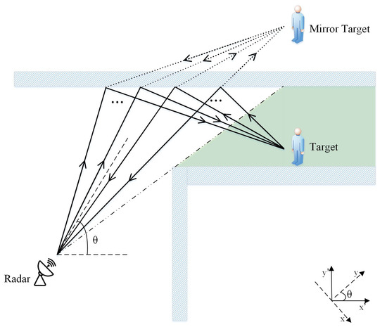
Figure 1.
Detection of target in NLOS of millimeter-wave radar via reflection.
Since the direction of the radar and the wall are not perpendicular or parallel, in order to facilitate solving the target position, we constructed two coordinate systems: the radar coordinate system and the geodetic reference coordinate system. Both coordinate systems take the transmitting antenna as the coordinate origin. The geodetic coordinate system takes the parallel direction and the vertical direction to the intermediate interface as the x-axis and the y-axis, respectively. The radar coordinate system takes the line where the receiving antenna array is located as the x-axis and its vertical direction as the y-axis. These two coordinate systems can be converted into each other according to the radar angle.
It is more convenient to solve the mirror target position based on the radar coordinate system. However, in the process of converting the mirror target coordinates to the real target coordinates, relevant scene parameters should be taken into consideration, such as the distance between the radar and the two walls and the width of the aisle. In this case, it is simpler to use the geodetic coordinate system.
Since the radar detects the target by the reflection of the intermediate interface in the NLOS scene, the echo signal contains multiple parts. In addition to the target-related signal, there are also direct backscattered signals from the intermediate interface and noise interference. Considering the forward and backward scattering of the interface, the wide beam angle of the radar and the variability of the target echo path, the radar echo signal model of the NLOS target is constructed as follows.
where includes random noise, background clutter and reflected echo from other objects. Considering that the actual radar beam angle is wide and the multi-point scattering exists on the intermediate interface, it can be analyzed that both and are the superposition of echo signals from multiple paths.
The expression of the reflected echo of the target is as follows.
Generally, in order to obtain a larger time bandwidth product and higher range and speed resolution, linear frequency-modulated continuous wave (LFMCW) is often used as the transmit signal. We define as the amplitude of the transmitted signal, as the path length of the signal from radar transmitter to radar receiver, and ,, and respectively represent the distance from the transmitting antenna to the first scattering point of the intermediate interface, distance from the first scattering point of the intermediate interface to the target, distance from the target to the second scattering point of the intermediate interface, and the distance from the second scattering point of the intermediate interface to the receiving antenna. According to the Fries transmission formula, the signal amplitude is inversely proportional to the propagation distance. Therefore, the expression of can be derived.
The direct backscattered signal of the intermediate interface is also the superposition of multiple path signals, and its expression is as follows.
where the direct backscattered, delay-attenuated signal of the intermediate interface can be expressed as
3. Detection Method of NLOS Moving Target
Since the echo signal received by the radar is scattered by the intermediate interface and target many times, the target echo signal is relatively weak. We propose a data processing method for NLOS targets. By solving the mirror target, which is symmetrical with the real target about the interface, the real target is located. Additionally, we utilize the polynomial fitting method and distance gating technology to suppress echo noise and improve the SNR.
According to the moving target detection theory and the constructed echo signal model of NLOS target, in terms of target parameter estimation, the two-dimensional FFT method is used to convert the time-domain echo signal into the range-Doppler domain to obtain the target’s distance and velocity, and the multiple signal classification (MUSIC) algorithm is used to estimate the target angle. In terms of noise suppression, we suppressed static noise by performing polynomial fitting on the range-slow time signal after range FFT. In addition, the distance gating technology is used to filter out other distance gate noises, and multi-channel non-coherent pulse accumulation is applied to amplify the SNR. The Constant False Alarm Rate (CFAR) detection method is performed on the result of pulse accumulation, and the results are clustered. Since we cannot know in advance how many targets there are in the scene, the Density-Based Spatial Clustering of Applications with Noise (DBSCAN) algorithm is quite suitable. Finally, the target is relocated according to the scene information, and the position coordinates of the real target are obtained by using the parameters of the mirror target in the radar coordinate system. The algorithm flow is shown in Figure 2. When actually processing the echo data, the data obtained by direct sampling are the difference frequency signal because the frequency of the millimeter wave is too high to be sampled. Then, we combine multiple consecutive echo signals from different receiving antennas into one frame. Next, each frame of data are processed to obtain the position and velocity information of the moving target. The specific algorithm procedure is shown in Algorithm 1.
| Algorithm 1: NLOS Target Detection Algorithm |
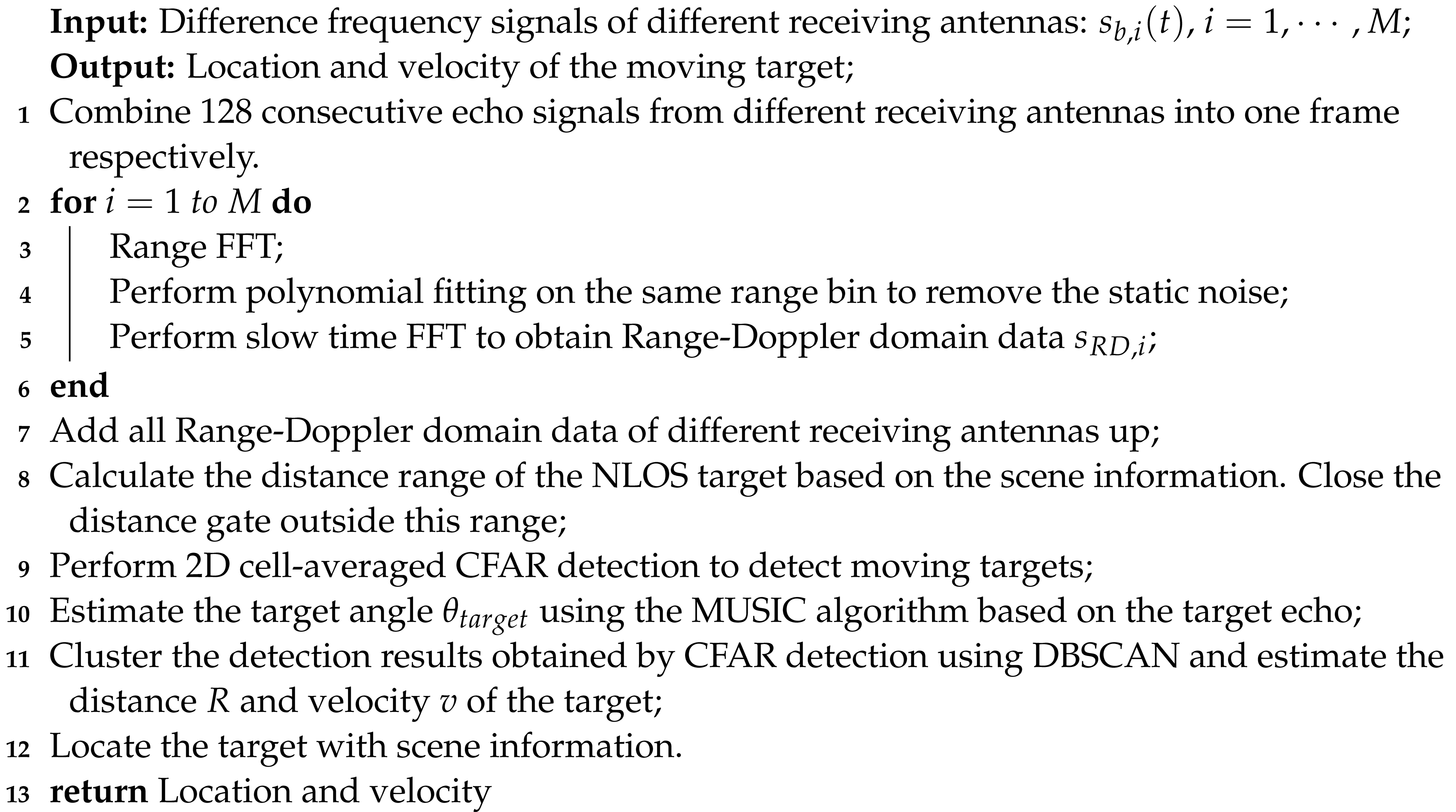 |
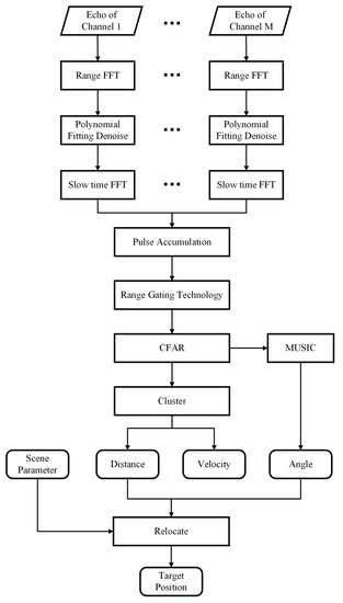
Figure 2.
Detection method of target in NLOS of millimeter-wave radar.
For convenience’s sake, some variables are defined and the meanings of the main variables are shown in Table 2. Methods of target parameter estimation and noise suppression will be introduced in detail in the following.
Table 2.
Meanings of the main variables used in the detection method of NLOS targets.
3.1. Target Parameter Estimation
3.1.1. Distance Estimation
The expression of the linear frequency modulation continuous wave emitted by the transmitting antenna of a single period is
When there is a target at a distance of R, the total time that the electromagnetic wave propagates in the air is
The echo signal is mixed with the transmitted signal. We define as the frequency output by the mixer, which is the difference between the frequency of the transmitted signal and the received signal.
where is the starting frequency, v is the target velocity, and is the frequency difference caused by the Doppler effect.
Since
So, the phase difference caused by the Doppler effect can be ignored. Then,
Then, the distance can be derived.
In practice, the corresponding frequency of the target can be obtained by sampling the output of the mixer and performing FFT on the sampled data. According to the above formula, the distance between the target and the radar can be obtained. Additionally, the range resolution can be calculated.
3.1.2. Velocity Estimation
Assuming that there is a moving target with a speed of v in the NLOS range, and the state of motion of the target does not change within one frame. Then, the distance between the mirror target and the radar changes with time.
where is the distance between the mirror target and the radar in the nth pulse repetition period, and is the distance between the mirror target and the radar at zero hour, is the pulse repetition time.
Then, the echo delay of the moving target is
Then, the echo signal obtained in the nth period is
The output signal of mixing and filtering is
Ignoring the term whose denominator is , the expression can be simplified as
We define that , then
It can be seen from the above formula that the frequency peak point obtained by FFT of multiple difference frequency signals obtained in one frame is
Then, the velocity of the target can be derived.
The velocity resolution is
3.1.3. Angle Estimation
The principle of the MUSIC algorithm is to eigenvalue decompose the covariance matrix of the received signal to obtain the signal subspace and the noise subspace. According to the orthogonality of the two subspaces, the spatial spectrum can be obtained, where the angle of the target can be determined by searching for the maximum value.
Assuming that there are P targets in the scene and the radar has M receiving antennas, then the received signal can be expressed as
where represents the received signal of the antenna array, A represents the steering vector matrix of the antenna array, represents the reflected signal of the target, and represents the noise.
According to the received signal, its covariance matrix can be calculated. The covariance matrix of the received signal can be expressed as
where represents the covariance matrix of the signal, represents the covariance matrix of the noise, and is the mean square error of Gaussian white noise. The eigenvalue of the covariance matrix is decomposed and sorted from largest to smallest. According to the signal source estimation method, the first P eigenvectors are the signal subspace, and the last eigenvectors are the noise subspace.
The spatial spectrum is defined as
where is the noise subspace matrix. Since the signal subspace is orthogonal to the noise subspace, the angle corresponding to the peak of the spatial spectrum is the angle of the target.
3.2. Noise Suppression Methods
3.2.1. Polynomial Fitting Denoising Method
If there are static objects in the scene, then the echo signal contains static noise. This will reduce the SNR of the echo signal, which will have a certain impact on the detection of moving targets. In response to this problem, we adopted a polynomial fitting method to filter out static noise.
The radar transmitter transmits chirp signals with a certain pulse repetition frequency, which reach the receiving antenna by scattering or reflecting by the intermediate interface and the target. The received echo signal is mixed with the transmitted signal to obtain an difference frequency signal. According to a certain frame rate, several difference frequency signals compose a two-dimensional signal. The range FFT is performed on it, and the range-slow time signal can be obtained.
Along the slow time direction, a low-order polynomial fitting is performed on the signal of the same range bin. We define as slow time and the expression of the nth range bin is
If there are static targets in the scene, the echo of the target is the same at any moment. Then, the difference frequency signals at different slow time points are the same in the range-slow time domain. Therefore, removing the invariant term obtained by polynomial fitting from the range-slow time domain signal can remove a part of the static noise and improve the SNR.
3.2.2. Range Gating Technology
The range gating technology determines the receiving time of the detector according to the transmission time of the pulse and the distance of the target, so that the target can be isolated from the background noise, and the influence of the direct backscattering of the intermediate interface and the multiple scattering of the target can be effectively reduced. The principle is to control the switch of the radar receiver by controlling the switch of the gate, so that the radar receiver only receives the echo signal within the range of the target, which improves the signal-to-noise ratio of the echo signal.
For millimeter wave radar, due to the high transmitted signal frequency, the echo signal cannot be directly sampled. So, the received signal and the transmitted signal are mixed first, then the difference frequency signal is sampled. Due to the limitation of the hardware equipment, the distance gating cannot be directly performed in the process of receiving the signal. Therefore, we adopt the frequency-domain distance gating method to filter out the interference of background clutter.
For the NLOS scene shown in Figure 3, the distance range of the NLOS target can be determined.
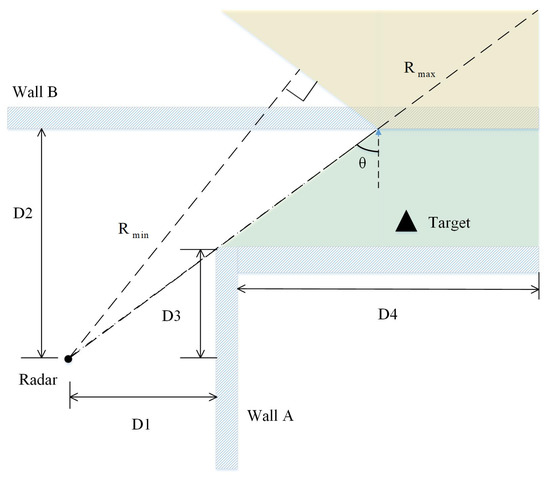
Figure 3.
The distance range of the mirror target of the NLOS moving target.
Therefore, the range gate outside this part should be closed in the range-Doppler domain to reduce noise interference. In addition, the distance door of other known obstacles in the NLOS scene should also be closed to further reduce the interference of background clutter.
4. Simulation and Experimental Results
In order to explore the feasibility of the above detection method of the NLOS moving target, we carried out simulations and experiments. The results are analyzed and summarized in detail as follows.
4.1. Simulation Results
We build the simulation scene as shown in Figure 4. There is a moving target (M) and a stationary target (S) in the scene, and the velocity of the moving target is 5 m/s. Set the radar working mode as one transmitter and four receivers, and the distance between adjacent receiving antennas is half the wavelength. The 128 continuously received echo signals are regarded as one frame. We have set up two coordinate systems, the radar coordinate system and the geodetic coordinate system, which are shown in Figure 4. The simulation parameters are shown in Table 3, where the target coordinates are based on the geodetic coordinate system.
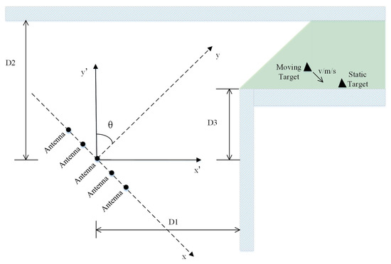
Figure 4.
Simulated NLOS scene.
Table 3.
Simulation parameters.
According to the principle of range estimation and velocity estimation, the range resolution and velocity resolution can be calculated.
According to the range gating technology proposed in this paper, in the simulation scene, the length of the echo path of the NLOS target satisfies
Considering that the range resolution of this scene is 0.25 m, the echo path length range of the NLOS target is approximately 8∼14 m.
According to the NLOS target echo signal model proposed in this paper, the signal received by the radar receiver includes target echo, direct backscattered signal from the intermediate interface and noise interference. In order to verify the effectiveness of the model, the target echo signal and the direct backscattered signal from the intermediate interface are simulated, respectively.
Firstly, the NLOS target echo signal is obtained by simulation, on which the detection method is applied to estimate the target parameters. The results are shown in Figure 5. It can be seen from the result that after two-dimensional FFT, there are two obvious targets in the range-Doppler domain. One target is a stationary target, and the other is a moving target with a velocity of about 5 m/s. Then, through CFAR detection and clustering, the parameters of the target are estimated. The stationary target is located at a distance of 10.13 m from the radar at an angle of 2.0, and the moving target is at a distance of 9 m from the radar at an angle of 4.5. There exists an error in the final positioning of the target, which is mainly due to low resolution and multipath effects.
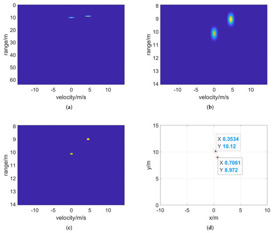
Figure 5.
Target detection results of target echo. (a) Two–dimensional FFT, (b) range–gated result, (c) CFAR detection and (d) position of clustered target in radar coordinates.
The path lengths of the echo signal of the target M are counted, and the path lengths distribution is shown in Figure 6. It can be seen that due to the multipath effect, the path length between 8.625 and 8.875 accounts for a relatively large portion. This length is greater than the direct distance between the radar and the mirrored target. In addition, the range resolution of the radar is 0.25 m. Therefore, the target distance estimated is slightly larger than the actual target distance.
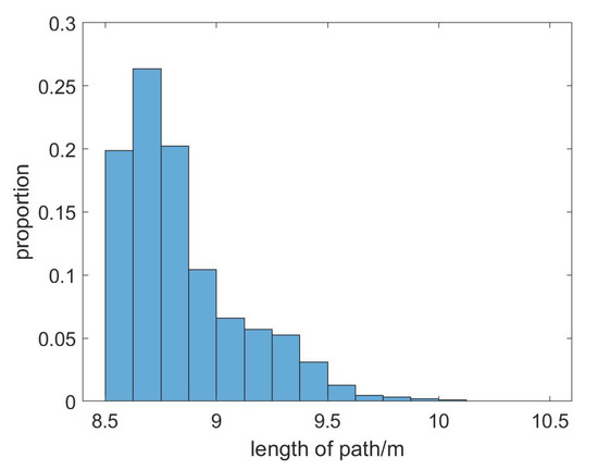
Figure 6.
Distribution of echo path length of a moving target.
For the direct backscattered signal from the intermediate interface, the same data processing method is applied as the target echo signal. The result is shown in Figure 7. It can be found that the direct backscattered signal from the intermediate interface forms an obvious stationary target point in the range-Doppler domain. Further, after CFAR detection and clustering, it can be obtained that the target is located at a distance of 5.5 m from the radar and the angle is 0. Obviously, the intermediary interface was mistakenly detected as a target point. In other words, the direct backscatter of the intermediate interface causes fake targets in the detection results.
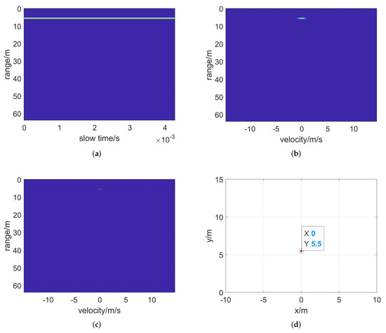
Figure 7.
Target detection results of the direct backscattered signal. (a) Range FFT, (b) two–dimensional FFT, (c) CFAR detection and (d) position of clustered target in radar coordinate.
In the above, the range of the echo path length of the NLOS target is calculated between 8 m and 14 m. Obviously, the distance parameter of the fake target caused by the intermediate interface is not within this range. The path lengths of the direct backscattered signal are counted, and the histogram of the path length distribution is shown in Figure 8.
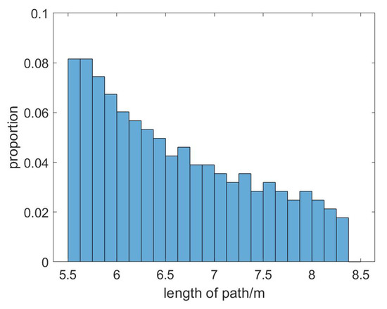
Figure 8.
Distribution of echo path length of the direct backscattered signal from the intermediary interface.
It can be seen from the figure that there are very few direct backscattering paths longer than 8 m. Therefore, if the distance gate outside the distance range is closed, the interference of direct backscatter can be greatly reduced.
In order to observe the effects of the polynomial fitting denoising method and the range gating technique more intuitively, the target detection results with and without denoising methods are shown and analyzed, respectively.
In the simulation scene, the echo signal received by the radar includes the echo signal of two targets, the direct backscattered signal of the intermediate interface and the noise interference. The NLOS target detection method without denoising operations is applied to process the signal, and the results are shown in Figure 9.
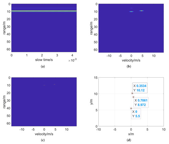
Figure 9.
Detection results without denoising operations for simulation echo. (a) Range FFT, (b) two–dimensional FFT, (c) CFAR detection and (d) position of clustered target in radar coordinates.
Obviously, in the range-Doppler domain, there are two strong point targets and one weak point target. CFAR detection method is performed on the range-Doppler domain signal to obtain three targets. After clustering and positioning, two stationary targets and one moving target are obtained. The estimated target parameters are shown in Table 4. Obviously, the two strong targets detected are the target points set in the scene. The stationary target located at 10.13 m is the target S, and the moving target located at 9 m is the target M. The weak target at 5.5 m is a fake target caused by the direct backscattered signal from the intermediate interface.
Table 4.
Estimated target parameters in the detection results without denoising operations for simulation data.
In order to reduce the impact of direct backscatter from the intermediate interface, the range gating technology is used to close the distance gate outside the range of the target’s echo signal path length. The results are shown in Figure 10.

Figure 10.
Detection results with range gating technology for simulation echo. (a) Two–dimensional FFT, (b) range–gated result, (c) CFAR detection and (d) position of clustered target in radar coordinates.
From the results, it is easy to find that there are only two obvious target points in the range-Doppler domain signal after the range gating. The influence of the direct backscattered signal from the interface is well eliminated. After clustering, two targets are finally detected, the stationary target (S) and the moving target (M) set in the scene. It can be seen that the fake target caused by the direct backscattered signal of the intermediate interface are completely filtered out. By comparing with the results of the detection method without denoising operations, it can be clearly concluded that the distance gating technology can greatly reduce the noise interference of other distance gates and improve the accuracy of target detection.
In order to detect moving targets more accurately and reduce the influence of static noise, the polynomial fitting denoising method proposed above is applied to eliminate static noise in the range-slow time domain. The results are shown in Figure 11.
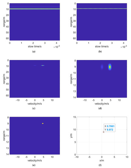
Figure 11.
Detection results with two denoising operations for simulation echo. (a) Range FFT, (b) polynomial fitting denoise, (c) velocity FFT, (d) range–gated result, (e) CFAR detection and (f) target position in radar coordinates.
From the results, it is easy to find that three obvious targets can be observed after the range FFT operation in the range-slow time domain. Then, after the polynomial fitting denoising operation, there is only one obvious target left. After applying the velocity FFT operation, there are one obvious moving target in the obtained range Doppler domain signal. CFAR detection is performed after distance gating, and there is only one moving target in the result obtained, and no stationary target. After using the MUSIC algorithm to estimate the angle of the target, the location of the target can be further determined. The distance of the target is estimated to be 9 m, the speed is estimated to be 5.015 m/s, and the angle is estimated to be 4.5. There is only the moving target in the final result. In other words, our NLOS moving target detection method can detect moving targets and filter out the interference caused by stationary targets. By comparing the results with the target detection method that only uses the range gating technology, it can be concluded that the polynomial fitting denoising method can greatly filter out the static noise, so the moving target can be detected more accurately.
In summary, we can draw several conclusions. First of all, the range gating technology can greatly reduce the influence of the direct backscattered signal from the intermediate interface, and filter out the noise outside the target distance range. Secondly, the polynomial fitting denoising method can effectively filter out static noise and detect moving targets more accurately. Finally, although there exists error in the final positioning of the target due to low resolution and multipath effects, the overall results are relatively accurate, indicating that the algorithm can realize the detection and parameter estimation of NLOS moving targets.
4.2. Experimental Results
The actual NLOS scene is more complicated. In order to verify the feasibility of the moving target detection method in the actual scene, we built an actual NLOS scene with the corner reflector as the actual target. The experiments are carried out with a millimeter wave radar, which is shown in Figure 12. We work with the received data using the NLOS target detection method above and analyze the results.
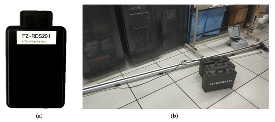
Figure 12.
Actual radar and scene. (a) Millimeter-wave radar, (b) the guide rail.
We build an NLOS scene in a meeting room in the New Main Building of Beihang University, and its abstract geometric model is shown in Figure 13. There are interference and static noise in the scene. The related parameters are shown in Table 5.
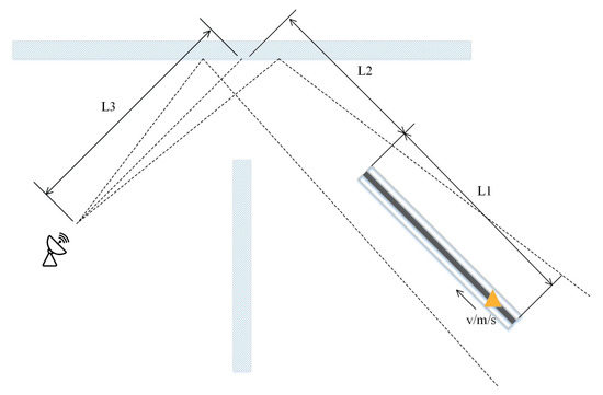
Figure 13.
Abstract geometric model of the actual NLOS scene.
Table 5.
Experimental parameters.
As shown in Figure 13, L1 is the length of the guide rail, L2 is the distance from the bottom of the guide rail to the center of the reflection point on the intermediate interface, and L3 is the distance from the radar to the center of the reflection point on the intermediate interface. The center of the reflection point of the intermediate interface is approximately the position of the intermediate interface directly opposite the center of the radar main lobe. In addition, since it is impossible to accurately measure the placement angle of the radar and the placement angle of the guide rail in the actual scene, the angle of the radar and the angle of the target are both roughly estimated.
The actual radar parameters are the same as the simulation parameters, so the range resolution and velocity resolution are also the same as the simulation. The range resolution is 0.25 m and the velocity resolution is 0.4530 m/s.
We mount the corner reflector on the guide rail and set the maximum speed of the guide rail to 1.5 m/s. The switch of the guide rail is controlled by software, and then, the movement of the corner reflector is controlled. The corner reflector moves from one end to another and back, and there is a process of acceleration and deceleration during the time. In this process, the echo signals received by the millimeter-wave radar are derived and processed. In order to verify the effectiveness of the two denoising methods proposed in this paper with actual data, the target detection method with and without denoising operation are respectively applied to one frame of the echoes, and the results are analyzed.
Firstly, the target detection method without denoising operation are applied to process the data, and the results are shown in Figure 14. The estimated target parameters are shown in Table 6. From the results, it can be found that after two-dimensional FFT, there are several targets in the range-Doppler domain, which is rather messy. Further, through CFAR detection and clustering, several target points are obtained. Combined with the information of the actual scene, it can be found that the point target with the strongest energy is the moving corner reflector. Other target points are caused by noise interference in the actual scene, which reflects that there exists interference and static noise in the actual scene.
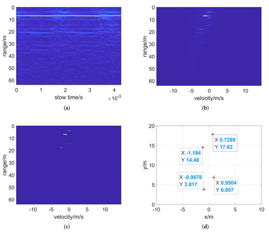
Figure 14.
Detection results without denoising operations for actual data. (a) Range FFT, (b) two–dimensional FFT, (c) CFAR detection and (d) position of clustered target in radar coordinates.
Table 6.
Estimated target parameters in the detection results without denoising operations for actual data.
Next, we choose the target detection method with range gating technology to process the data, and the results are shown in Figure 15. Obviously, after the range gating operation, there exist an obvious moving target and a weak stationary target in the range-Doppler domain signal. After the range gating, the noise interference outside the range of the NLOS target echo signal path length is filtered out. Therefore, the number of targets finally detected is much less than that of the target detection method without denoising operation. Therefore, it can also be reflected that the distance gating technology can greatly reduce the noise interference of other distance gates.
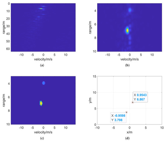
Figure 15.
Detection results with range gating technology for actual data. (a) Two–dimensional FFT, (b) range−gated result, (c) CFAR detection and (d) position of clustered target in radar coordinates.
Finally, the polynomial fitting denoising method and range gating technology are both applied to process the data, and the results are shown in Figure 16. It can be seen from the results of the range FFT that there are noise and other interference in the echo signal received by the radar. After denoising by polynomial fitting, a part of static noise is removed. After velocity FFT and distance gating, an obvious moving target can be observed in the range-Doppler domain. At the same time, there is still weak noise in the signal. After CFAR detection, the moving target is accurately detected. The DBSCAN clustering algorithm is used to process the results of CFAR detection, and finally, the target is located and its velocity is estimated. Finally, it can be detected that the target with a velocity of 1.14 m/s is located at 6.94 m and 8.00 to the left of the center of the radar beam, which is consistent with the scene information. Due to the limitations of hardware equipment, precise target parameters cannot be obtained.
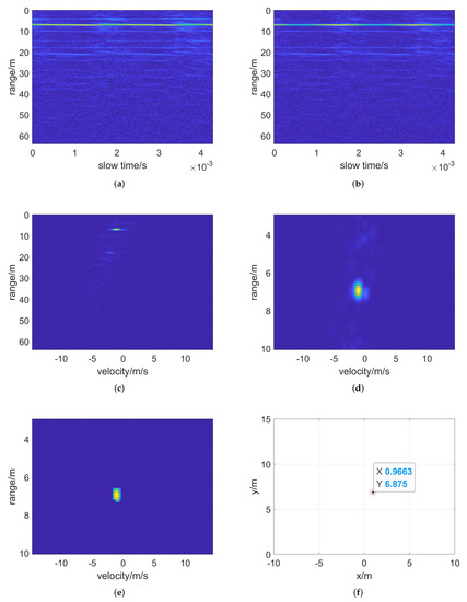
Figure 16.
Detection results with two denoising operations for actual data. (a) Range FFT, (b) polynomial fitting denoise, (c) velocity FFT, (d) range−gated result, (e) CFAR detection and (f) target position in radar coordinates.
Comparing the results obtained by the above three target detection methods, we can easily find that the range gating technology can filter out all the noise outside the distance range of the NLOS target, which greatly reduces the influence of the direct backscattered signal from the intermediate interface. The polynomial fitting denoising method can filter out static noise and effectively reduce the influence of some static objects in the actual scene. In general, the NLOS target detection method proposed can accurately detect NLOS moving targets and greatly reduce the impact of noise interference, which has been verified in an actual scene.
By comparing the data processing process and results of the simulation and the actual measurement, it can be found that there are some differences, which can be mainly divided into two points. Firstly, the actual experimental environment is more complex. The echoes received by the radar are more cluttered due to the presence of many interfering objects in the scene. Besides, the surrounding wind carried by the moving target will also form clutter interference. Another difference is that the electromagnetic wave propagation in the actual experimental scene has a large loss due to the influence of dust particles and gas molecules in the air, which is not considered in the simulation scene. In the air, the echo signal with a long propagation path has a larger loss than the short path, so the echo signal energy of the mirror reflection propagation path accounts for a larger proportion. Further, the influence caused by the multipath effect is weaker and the target location information of the actual experimental results is more accurate. In conclusion, whether simulation or experiment, the moving target is accurately detected and the static noise is filtered out, which verifies the effectiveness of the NLOS target detection method.
In actual scene, there exists an error in the final positioning of the target. In the actual scene, there are many factors that affect the positioning error. It mainly includes the measurement error of some parameters in the actual NLOS scene, the deviation of the radar placement angle, the multipath effect, and low distance and angle resolution. Although there exist errors in practice, the method still has high accuracy and applicability. Different actual NLOS scenes are built and the echo data are collected by millimeter-wave radar. The NLOS moving target detection method was applied on the echo data of various NLOS scenes. From the results of target detection, the method proposed in this paper can accurately detect the NLOS moving target, which shows that it has good stability and universality. This is related to the denoising method adopted by this paper. In the algorithm proposed in this paper, range gating technology is used to filter out the interference caused by wall backscattering and multiple reflections, and the polynomial fitting denoising method is used to remove the static noise. These two methods do not depend on a fixed scene, and can work well in different NLOS scenes, so that moving objects can be detected accurately.
For the same experimental echo data, we applied the NLOS moving target location algorithm proposed by Zhao Qingsong [32,33], and the results are shown in Figure 17. From the results, it can be seen that after moving target indication (MTI), although the static noise is filtered out, the echo energy of the moving target is also greatly reduced. This algorithm estimates that the distance between the target and the radar is 7 m, which is similar to the distance estimation result of the method proposed in this paper and consistent with the scene information. However, the angle of the NLOS moving target detected by this method is 0.23 degrees by multiple channels’ phase comparison, which is quite different from the actual experimental scene. It shows that the angle estimated by the MUSIC algorithm is more accurate than the multi-channel comparison method. This algorithm procedure is simple and the calculation speed is fast. Compared with this, the NLOS moving target detection method proposed in this paper is computationally slower, due to the lager calculation because of the addition of velocity estimation and the MUSIC method.
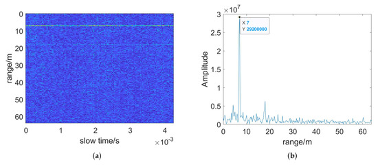
Figure 17.
Detection results of the NLOS moving target location algorithm proposed by Zhao Qingsong. (a) Range FFT after MTI, (b) target range estimation after accumulation.
By comparing the results of the NLOS moving target detection method proposed in this paper and the NLOS moving target location algorithm, it is easy to find that there are two main differences. Firstly, in the actual NLOS scene, the target angle estimated by the multi-channel comparison method has a large error, while the MUSIC algorithm can locate the target more accurately. The second difference is that the NLOS moving target detection method proposed in this paper can estimate the velocity of the target while detecting and locating the target, which provides support for predicting its motion state. Therefore, the method proposed in this paper is more suitable when the target’s velocity needs to be obtained.
5. Conclusions
In conclusion, this paper studies the NLOS scene and abstracts its geometric model. On this basis, an NLOS target multipath echo signal model based on the reflection principle is constructed. Then, an NLOS moving target detection method based on reflective radar is proposed, which is expected to detect the NLOS targets with low power. Polynomial fitting method and range gating technology are applied to the NLOS moving target detection method to suppress noise. Finally, the target is detected by CFAR detection and DBSCAN clustering. In addition, the target’s position and velocity parameters are estimated by two-dimensional FFT and MUSIC algorithm.
From the processing results of simulation data and measured data, we can come to a conclusion. The range gating technology can filter out the range gate noise outside the range of the NLOS target, which greatly reduces the influence of the direct backscattered signal of the intermediate interface and the multiple reflection signal of the target. The polynomial fitting denoising method can filter out most of the static noise, which can effectively cut down the influence on the detection results when there are static objects in the actual scene. We carried out simulation experiments on the two important parts of the NLOS target echo signal model, and analyzed the influence of multipath effects on the target detection results. The accuracy of the NLOS target echo signal model proposed in this paper is verified. In addition, experiments on actual scenes were carried out, and the actual data are obtained. By processing simulation data and measured data separately, and comparing the detection results of target detection methods with and without denoising operation, it was verified that the two denoising methods proposed in this paper have great effects in actual scenes.
In future work, the echo signal model of NLOS target will be further improved. More NLOS moving target detection methods will be studied in depth to improve the accuracy of target detection.
Author Contributions
Conceptualization, Y.W. and B.S.; methodology, Y.W.; software, Y.W.; validation, Y.W., Y.Z. and H.W.; formal analysis, Y.W. and H.W.; investigation, Y.W. and Y.Z.; resources, B.S.; data curation, Y.W.; writing—original draft preparation, Y.W.; writing—review and editing, B.S.; visualization, Y.W.; supervision, B.S.; project administration, B.S.; funding acquisition, B.S. All authors have read and agreed to the published version of the manuscript.
Funding
This research was funded by National Natural Science Foundation of China grant number 62071022.
Institutional Review Board Statement
Not applicable.
Informed Consent Statement
Not applicable.
Data Availability Statement
Not applicable.
Conflicts of Interest
The authors declare no conflict of interest.
Abbreviations
The following abbreviations are used in this manuscript:
| NLOS | Non-line-of-sight |
| LOS | Line-of-sight |
| FFT | Fast Fourier Transform |
| MUSIC | Multiple Signal Classifications |
| BP | Back Projection |
| CCD | Coherent Change Detection |
| MIMO | Multiple Input Multiple Output |
| CRATFR | Comprehensive Range Accumulation Time-Frequency Transform |
| PIIC | Position Information Indexd Classifier |
| SIMO | Single Input Multiple Output |
| SNR | Signal-to-noise Ratio |
| CFAR | Constant False Alarm Rate |
| DBSCAN | Density-Based Spatial Clustering of Applications with Noise |
| MTI | Moving Target Indication |
References
- You, Y.; Qiao, L.; Zhao, Z. Simulation-based configurations study of active millimetre-wave imaging system for personal security. J. Eng. 2019, 2019, 6130–6133. [Google Scholar] [CrossRef]
- Xiao, Z.; Lu, X.; Yan, J.; Wu, L.; Ren, L. Automatic detection of concealed pistols using passive millimeter wave imaging. In Proceedings of the 2015 IEEE International Conference on Imaging Systems and Techniques (IST), Macau, China, 16–18 September 2015; pp. 1–4. [Google Scholar] [CrossRef]
- Huang, X.; Niu, J. cTracker: A fast-indoor people detection and tracking system based on mmWave radar sensor. Chin. J. Sci. Instrum. 2020, 41, 130–139. [Google Scholar]
- Bleh, D.; Rösch, M.; Kuri, M.; Dyck, A.; Tessmann, A.; Leuther, A.; Wagner, S.; Weismann-Thaden, B.; Stulz, H.P.; Zink, M.; et al. W-Band Time-Domain Multiplexing FMCW MIMO Radar for Far-Field 3-D Imaging. IEEE Trans. Microw. Theory Tech. 2017, 65, 3474–3484. [Google Scholar] [CrossRef]
- Salnykov, D.; Dudka, A.; Tsopa, A. Security analysis of wireless communication systems of the millimeter waves band. In Proceedings of the 2018 IEEE 9th International Conference on Dependable Systems, Services and Technologies (DESSERT), Kyiv, Ukraine, 24–27 May 2018; pp. 645–648. [Google Scholar] [CrossRef]
- Araghi, A.; Khalily, M.; Xiao, P.; Kosari, A.; Zarrabi, H.; Tafazolli, R. Millimeter-Wave MIMO Balanced Antipodal Vivaldi Antenna Design for Autonomous Cars. In Proceedings of the 2018 International Symposium on Networks, Computers and Communications (ISNCC), Rome, Italy, 19–21 June 2018; pp. 1–4. [Google Scholar] [CrossRef]
- Zhang, Q.; Sun, H.; Wei, Z.; Feng, Z. Sensing and Communication Integrated System for Autonomous Driving Vehicles. In Proceedings of the IEEE INFOCOM 2020—IEEE Conference on Computer Communications Workshops (INFOCOM WKSHPS), Toronto, ON, Canada, 6–9 July 2020; pp. 1278–1279. [Google Scholar] [CrossRef]
- Xin, W.; Lu, Z.; Weihua, G.; Pcng, F. Active Millimeter-Wave Near-Field Cylindrical Scanning Three-Dimensional Imaging System. In Proceedings of the 2018 International Conference on Microwave and Millimeter Wave Technology (ICMMT), Chengdu, China, 7–11 May 2018; pp. 1–3. [Google Scholar] [CrossRef]
- Shaobei, L.; Shiyong, L. Target Detection and Recognition Based on Active Millimeter-Wave Imaging System. In Proceedings of the 2019 IEEE 2nd International Conference on Electronics Technology (ICET), Chengdu, China, 10–13 May 2019; pp. 74–77. [Google Scholar] [CrossRef]
- Caris, M.; Johannes, W.; Stanko, S.; Pohl, N. Millimeter wave radar for perimeter surveillance and detection of MAVs (Micro Aerial Vehicles). In Proceedings of the 2015 16th International Radar Symposium (IRS), Dresden, Germany, 24–26 June 2015; pp. 284–287. [Google Scholar] [CrossRef]
- Wang, K.; Zeng, Z.; Sun, J. Through-Wall Detection of the Moving Paths and Vital Signs of Human Beings. IEEE Geosci. Remote Sens. Lett. 2019, 16, 717–721. [Google Scholar] [CrossRef]
- Nkwari, P.; Sinha, S.; Ferreira, H.C. Through-the-Wall Radar Imaging: A Review. IETE Tech. Rev. 2018, 35, 631–639. [Google Scholar] [CrossRef]
- Jin, T.; Song, Y. Review on human target detection using through-wall radar. Chin. J. Radio Sci. 2020, 35, 10. [Google Scholar]
- Qi, F.; Liang, F.; Lv, H.; Li, C.; Chen, F.; Wang, J. Detection and Classification of Finer-Grained Human Activities Based on Stepped-Frequency Continuous-Wave Through-Wall Radar. Sensors 2016, 16, 885. [Google Scholar] [CrossRef] [PubMed]
- Song, Y.; Hu, J.; Chu, N.; Jin, T.; Zhang, J.; Zhou, Z. Building Layout Reconstruction in Concealed Human Target Sensing via UWB MIMO Through-Wall Imaging Radar. IEEE Geosci. Remote Sens. Lett. 2018, 15, 1199–1203. [Google Scholar] [CrossRef]
- Wang, X.; Li, G.; Wan, Q.; Burkholder, R.J. Look-Ahead Hybrid Matching Pursuit for Multipolarization Through-Wall Radar Imaging. IEEE Trans. Geosci. Remote Sens. 2017, 55, 4072–4081. [Google Scholar] [CrossRef]
- Wang, X.; Li, G.; Liu, Y.; Amin, M.G. Two-Level Block Matching Pursuit for Polarimetric Through-Wall Radar Imaging. IEEE Trans. Geosci. Remote Sens. 2018, 56, 1533–1545. [Google Scholar] [CrossRef]
- Lu, B.; Song, Q.; Zhou, Z.; Wang, H. A SFCW radar for through wall imaging and motion detection. In Proceedings of the 2011 8th European Radar Conference, Manchester, UK, 12–14 October 2011; pp. 325–328. [Google Scholar]
- Jin, L.; Ouyang, S.; Zhou, L. Array design and imaging method for ultra-wideband multiple-input multiple-output through-the-wall radar. J. Electron. Inf. Technol. 2012, 34, 1574–1580. [Google Scholar] [CrossRef]
- Cai, J. Research on Through-the-Wall Radar Imaging Based on Group Sparse Compressed Sensing. Ph.D. Thesis, Nanjing University of Science and Technology, Nanjing, China, 2017. [Google Scholar]
- Dai, Y. Sparse Imaging Technology Research for Ultrawideband Through-the-Wall Radar. Ph.D. Thesis, Guilin University of Electronic Technology, Guilin, China, 2018. [Google Scholar]
- Qi, F.; Liang, F.; Liu, M.; Lv, H.; Wang, P.; Xue, H.; Wang, J. Position-Information-Indexed Classifier for Improved Through-Wall Detection and Classification of Human Activities Using UWB Bio-Radar. IEEE Antennas Wirel. Propag. Lett. 2019, 18, 437–441. [Google Scholar] [CrossRef]
- Du, H.; Jin, T.; Song, Y.; Dai, Y.; Li, M. A Three-Dimensional Deep Learning Framework for Human Behavior Analysis Using Range-Doppler Time Points. IEEE Geosci. Remote Sens. Lett. 2020, 17, 611–615. [Google Scholar] [CrossRef]
- Zhang, Y.; Xia, T. In-Wall Clutter Suppression Based on Low-Rank and Sparse Representation for Through-the-Wall Radar. IEEE Geosci. Remote Sens. Lett. 2016, 13, 671–675. [Google Scholar] [CrossRef]
- Leigsnering, M.; Ahmad, F.; Amin, M.G.; Zoubir, A.M. Compressive Sensing-Based Multipath Exploitation for Stationary and Moving Indoor Target Localization. IEEE J. Sel. Top. Signal Process. 2015, 9, 1469–1483. [Google Scholar] [CrossRef]
- Kirmani, A.; Hutchison, T.; Davis, J.; Raskar, R. Looking around the corner using ultrafast transient imaging. Int. J. Comput. Vis. 2011, 95, 13–28. [Google Scholar] [CrossRef]
- Heide, F.; Xiao, L.; Heidrich, W.; Hullin, M.B. Diffuse mirrors: 3D reconstruction from diffuse indirect illumination using inexpensive time-of-flight sensors. In Proceedings of the IEEE Conference on Computer Vision and Pattern Recognition, Columbus, OH, USA, 23–28 June 2014; pp. 3222–3229. [Google Scholar]
- Gupta, O.; Willwacher, T.; Velten, A.; Veeraraghavan, A.; Raskar, R. Reconstruction of hidden 3D shapes using diffuse reflections. Opt. Express 2012, 20, 19096–19108. [Google Scholar] [CrossRef] [PubMed]
- Laurenzis, M.; Velten, A. Non-line-of-sight active imaging of scattered photons. In Electro-Optical Remote Sensing, Photonic Technologies, and Applications VII and Military Applications in Hyperspectral Imaging and High Spatial Resolution Sensing; International Society for Optics and Photonics: Bellingham, WA, USA, 2013; Volume 8897, p. 889706. [Google Scholar]
- Laurenzis, M.; Christnacher, F.; Velten, A. Study of a dual mode SWIR active imaging system for direct imaging and non-line-of-sight vision. In Laser Radar Technology and Applications XX; and Atmospheric Propagation XII; International Society for Optics and Photonics: Bellingham, WA, USA, 2015; Volume 9465, p. 946509. [Google Scholar]
- Kaida, X.; Weiqi, J.; Jing, L.; Su, Q.; Xunqing, T. Non-line-of-sight imaging based on laser range-gated imaging technology. Infrared Laser Eng. 2012, 41, 2073–2078. [Google Scholar]
- Zhao, Q.; Cui, G.; Guo, S.; Yi, W.; Kong, L.; Yang, X. Millimeter Wave Radar Detection of Moving Targets Behind a Corner. In Proceedings of the 2018 21st International Conference on Information Fusion (FUSION), Cambridge, UK, 10–13 July 2018; pp. 2042–2046. [Google Scholar] [CrossRef]
- Zhao, Q. Non-Line-of-Sight Target Multipath Detection Method Based on Millimeter Wave Radar. Ph.D. Thesis, University of Electronic Science and Technology of China, Chengdu, China, 2019. [Google Scholar]
Publisher’s Note: MDPI stays neutral with regard to jurisdictional claims in published maps and institutional affiliations. |
© 2022 by the authors. Licensee MDPI, Basel, Switzerland. This article is an open access article distributed under the terms and conditions of the Creative Commons Attribution (CC BY) license (https://creativecommons.org/licenses/by/4.0/).