Abstract
Widespread ground fissures caused by coal mining subsidence are a main cause of ecological destruction in coal mining areas, and the rapid monitoring of ground fissures is essential for ecological restoration. Traditional fissure monitoring technologies are time consuming and laborious. Therefore, we developed a method to automatically extract ground fissures from high-resolution UAV images. First, a multiscale Hessian-based enhancement filter was utilized to enhance the ground fissures in grayscale images. Then, a simple single-thresholding operation was applied to segment the enhanced image to generate a binary ground fissure map. Finally, incomplete path opening was performed to eliminate the noises in the fissure extraction results. We selected the N1212 working face of the Ningtiaota Coal Mine in Shenmu County, China, as the study area. The results indicated that the ranges of correctness, completeness, and the kappa coefficient of the extracted results were 66.23–79.00%, 69.03–73.22%, and 67.91–75.88%, respectively. Image resolution is the key factor for successful fissure detection; the method proposed in this paper can extract ground fissures with a width greater than one pixel (2.64 cm), and the detection ratio for fissures with a width greater than two pixels was over 87%. Our research has solved the problem of the rapid monitoring of ground fissures to a certain extent and can act as a valuable tool for ecological restoration in mining areas.
1. Introduction
Coal is a valuable chemical material and energy source that has long held the second largest share of world energy consumption, with total world production exceeding 7500 Mt in 2020 []. Coal mining has created a series of environmental degradation problems. Coal mining can be divided into open-pit and underground mining. Unlike open-pit mining, which directly damages the ground, underground mining causes ground subsidence by destroying the underground rock strata, thus affecting the ecological environment. Large-scale ground subsidence has led to the development of numerous ground fissures, especially in ecologically fragile arid areas [].
Ground fissures created due to mining subsidence cause changes in soil properties, reduce soil quality [], and decrease surface soil moisture [] in the region where they are distributed. At the same time, ground fissures also result in mechanical damage to plant roots [,], affecting the expected growth of vegetation, leading to vegetation degradation and aggravated soil erosion in coal mining areas [,]. Ground fissures may even penetrate the underground mining space, seriously threatening the safety of mine production []. Therefore, rapid investigation and the mapping of ground fissures that have been caused by mining subsidence are essential for ecological restoration in mining areas.
Traditionally, ground fissure maps are obtained by field surveys through the use of a total station, GPS, and other means to measure the plane position of ground fissures [,]. Due to the dense distribution of ground fissures in mining areas, the field surveys are time consuming and labor intensive. According to actual fissure survey data, the width of ground fissures is usually at the sub-meter level [,,], meaning that the resolution of current optical satellite images cannot clearly display ground fissures. Nowadays, UAV photogrammetry and remote sensing technologies are undergoing rapid development and have been widely used in many fields []. UAV photogrammetry is cheap and highly efficient, and it can provide images with a resolution in the centimetric range, making it possible to rapidly monitor ground fissures in mining areas.
Visual interpretation of high-resolution images, a classical method to determine linear feature extraction, cannot meet the demands of massive ground fissure detection; therefore, an automatic extraction algorithm is vital. At present, the combination of UAV photogrammetry and an automatic extraction method is frequently applied for fissure detection research in bridges, roads, and landslides [,,,,,]; however, relatively few studies have explored the application of automatic approaches for the ground fissure mapping in mining areas. Zhang et al. [] proposed a fissure identification algorithm based on machine learning to detect ground fissures from UAV images of the mining subsidence area in the eolian sand area of western China. Jia et al. [] successfully detected ground fissures via high-resolution UAV images using the matched filtering method. Zhao et al. [] innovatively used thermal infrared images from a UAV and an edge detection operator for fissure extraction in a mining subsidence area. There are various types of ground fissures, and different mining areas have various and complex surface backgrounds; however, the existing research either has a small research scope or relies on land cover information, so it is doubtful as to whether these automatic extraction methods are universal.
Based on this context, we propose a method for the automatic extraction of mining-induced ground fissures from high-resolution UAV images. The developed method is based on a combination of multiscale Hessian-based enhancement filters and incomplete path openings and was tested in the mining subsidence area of the Ningtiaota Coal Mine. The obtained results were compared to the reference data produced by experts by means of visual interpretation. The aim of this paper is to propose an automatic ground fissure extraction method that has high generality and that can quickly monitor ground fissures in mining areas and can accurately diagnose ecological damage.
2. Types of Ground Fissure Observed in Mining Area
Ground fissures result from the coupling of the movement of the overlying strata and the deformation of the topsoil in the mined-out area after coal mining has taken place. The formation process is a complex mechanical one involving rocks and soil. Based on the formation mechanism, ground fissures can be classified into three types: tensile fissures (Figure 1a), sliding fissures (Figure 1b), and collapsing fissures (Figure 1c) []. When the tensile stress generated by the ground movement and deformation exceeds the ultimate tensile strength of the soil, it will undergo tensile failure and form a tensile fissure []. The movement and deformation of the ground surface cause the slippage of steep slopes in mountainous or valley terrains, and local breakage occurs to form the sliding fissure []. Moreover, the collapsing fissure is formed by the shear failure of the overlying rock and soil above the mined-out area, which is caused by breaking the key stratum (hard strata) that controls surface subsidence []. This type of fissure has the characteristics of considerable width and a large step drop.

Figure 1.
Different types of ground fissures: (a) tensile ground fissures; (b) sliding ground fissures; and (c) collapsing ground fissures.
3. Study Area and Materials
3.1. Study Area
The study area is located above the N1212 working face of the Ningtiaota Coal Mine (38°58′–39°6′N, 110°9′–110°17′E) in the northern part of the Loess Plateau, and the southeastern edge of the Mu Us Desert, which lies within Shenmu County, Shaanxi Province, China (Figure 2). The vegetation is sparse in the study area, and the vegetation types mainly comprise shrubs and grasslands. The study area’s elevation ranges from 1220 to 1338 m, making it a typical loess gully region with complex geomorphology (Figure 3). The average annual rainfall is about 434.1 mm, which is concentrated in July, August, and September, and the annual average temperature is 8.6 °C.
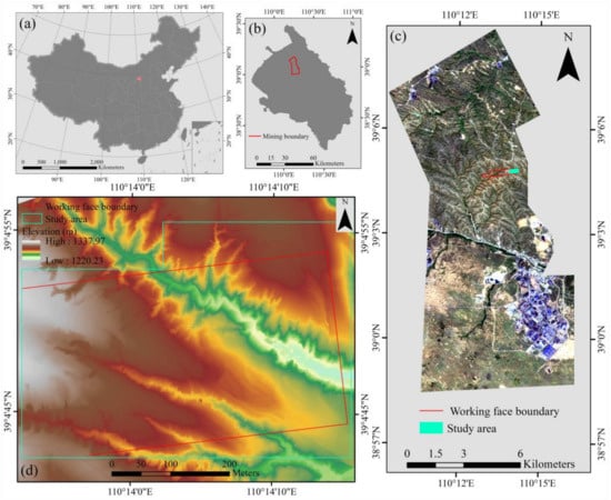
Figure 2.
The geographical location of the study area. (a,b) location of the Ningtiaota mine in China, (c) location of the study area in the Ningtiaota mine, (d) the study area with topographic map as the background.

Figure 3.
(a–c) Geomorphology of the study area.
The Ningtiaota Coal Mine, where the study area is located, spans east–west for 10 km, spans north–south for 19 km, has a total area of 119.77 km2, and a coal production capacity of more than 18.00 Mt/a and is categorized as an underground mine. High-intensity underground coal mining has caused a large number of ground fissures, collapses, and landslides on the surface of the study area, and gullies have formed after the surface runoff formed by rainfall, intensifying soil erosion.
3.2. Data Acquisition and Preprocessing
A DJI Matrice 210 RTK with a professional-grade digital camera (the Zenmuse X5S) mounted on a three-axis gimbal was used for image acquisition. The main camera parameters are listed in Table 1, and detailed information can be found on the product’s official website (DJI. https://www.dji.com/ (accessed on 13 January 2022)).

Table 1.
The main camera parameters for the Zenmuse X5S.
UAV images were acquired on 21 April 2019, images were taken in sunny and breezy weather conditions. The front overlap and side overlap of the UAV missions were 80% and 55%, respectively, and the ground sampling distance (GSD) was 1.8 cm at a flight altitude of 80 m. A total of 377 photos covering the entire area were obtained in JPEG format. The Matrice 210 RTK was able to provide high-precision horizontal position and elevation information [], and the ground surface of the study area had moved due to coal mining subsidence. Therefore, we did not set ground control points. Pix4D mapper software (Pix4D, Lausanne, Switzerland) was used to process the collected images to generate a digital orthophoto map (DOM) and digital surface model (DSM) of the study area with a resolution of 2.64 cm.
4. Methods
Although the first general edge detection algorithms were proposed in the 1980s [,], linear feature extraction is still a challenging task in many fields, such as medical research [], geoscience [,], and signal processing []. For our research, the main challenges affecting automatic fissure detection are as follows: (1) the approach should be able to detect ground fissures of different widths and directions simultaneously; (2) the approach should not respond to edges but should instead enable the detection of dark curvilinear structures; (3) unlike roads, rivers, and blood vessels, ground fissures are not necessarily continuous linear structures, and broken fissures cannot be connected simply by morphological operators. Considering these challenges, we developed a processing workflow that included three main stages to extract ground fissures. First a multiscale Hessian-based enhancement filter [,] was used to filter the grayscale images to enhance the ground fissures. Second, a simple single-thresholding operation was used to distinguish ground fissures from the image background and to generate a binary fissure map. Finally, for the incomplete path openings [,], a flexible morphological operator was performed to eliminate some of the false positives.
4.1. Multiscale Hessian-Based Enhancement Filtering
The multiscale Hessian-based enhancement filter is an efficient vessel enhancement algorithm that is widely used in the field of medical image processing [,,]. Some related works applied this enhancement filter for the detection of fissures in multicrystalline solar cells and pavements [,]. In this study, we utilized the multiscale Hessian-based fissure filter to perform fissure enhancement and background suppression operations.
The local intensity of the grayscale image of the study area can be expressed using the Taylor expansion of the relationship between pixel and its neighborhood, which has a granularity []:
where is the two-dimensional column vector of the pixel position, and are, respectively, the gradient vector and Hessian matrix at pixel in the image at scale . The Hessian matrix at scale is given as follows:
Here, is the second-order partial derivative of the image . In order to facilitate the differential operation in the image while also reducing the effect of noise [], the second derivative of the Gaussian function was used as the convolution kernel to process the image . The second-order partial derivative of the image can be described as follows:
where is the normalization factor, and is the two-dimensional Gaussian function with standard deviation σ, which is written as follows:
where is the square sum of the elements and in column vector . Therefore, the Hessian matrix at pixel in the image at scale is expressed as follows:
The two eigenvalues and of the Hessian matrix and their corresponding eigenvectors can be solved. Considering the gray value, the image can be regarded as a curved surface. The eigenvalues and are the two principal curvatures at the pixel of this curved surface, and the corresponding eigenvectors are the principal directions. Figure 4 shows the fissure morphology in the grayscale image as well as the schematic diagram of the principal curvatures of the fissure segment. The eigenvalues and of the ground fissures have the following properties []:
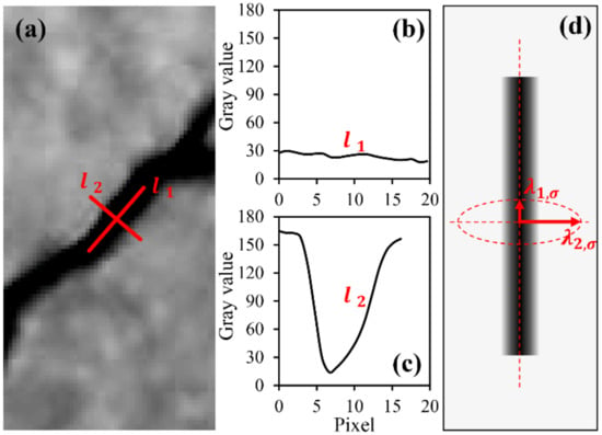
Figure 4.
Fissure morphology and principal curvatures: (a) fissure fragment in the grayscale image; (b) profile along fissure segment; (c) profile perpendicular to fissure segment; and (d) schematic diagram of principal curvatures of fissure segment.
In order to highlight the ground fissures in the image so that the fissures have a sharp contrast with the complex background, our research used the ground fissure measurement function shown below:
where and are applied to adjust the sensitivity weights of the measures and . Commonly, the value of is 0.5, and the value of is related to the overall intensity of the image. The value of ranges from 0 to 1, and the closer it is to 1, the more robust the ground fissure response is.
The scale of the measurement function is continuously adjusted to adapt to ground fissures of different widths. In this paper, we select 70 cross-sections of ground fissures with different widths and fit their gray curves to calculate , which is set from 0.5 to 2.4 according to the actual situation in the study area (Figure 5). Additionally, the maximum response value in each scale is used as the fissure measurement at pixel to maximize fissure enhancement:
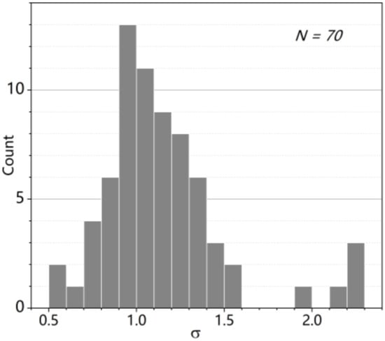
Figure 5.
The distribution of 70 cross-sections of ground fissures with different widths in the study area.
4.2. Thresholding
After multiscale Hessian-based enhancement filtering, the ground fissures showed significant differences from the image background. Therefore, a simple single-thresholding operation was used to effectively segment the ground fissures and the image background and to generate a binary ground fissure map. It should be noted that a low threshold will cause many false positives to be present in the binary fissure map, while a high threshold will eliminate narrow-width fissures; so, the actual situation should be considered when determining the global threshold for image segmentation. In this paper, the mean and standard deviation (std) of the intensity of the enhanced image was calculated, and the global thresholds were, respectively, set to mean, mean + 0.5 std, mean + 1 std, mean + 2 std, and mean + 3 std. The fissure detection results (Figure 6) under different global thresholds revealed that there were a lot of noises in the binary ground fissure maps corresponding to the threshold mean and mean + 0.5 std (Figure 6b,c). Although the extraction effect of the threshold mean + 1 std was improved, there were still noises that were mixed and connected with fissures (Figure 6d), and the threshold mean + 3 std underestimated the fissure pixels, resulting in the fissures continuously breaking into short fragments (Figure 6f). The threshold mean + 2 std achieved a good balance between ground fissure extraction and noise suppression (Figure 6e). Therefore, in our research, mean + 2 std was selected as the global threshold to segment the images that were enhanced by multiscale Hessian-based enhancement filtering.
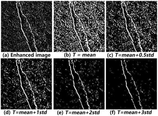
Figure 6.
The enhanced image (a) and ground fissure extraction results under different global thresholds (b–f).
4.3. Incomplete Path Openings
Due to visually similar objects, such as elongated shadows caused by micro-topography, the binary ground fissure map generated by the described routine still comprises numerous types of noise, which are similar in shape to the short fragments of ground fissures. Normally, noises are distributed in a disorderly manner, with the small ground fissure fragments closely arranged and having a clear tendency to extend (Figure 7). However, due to the different widths and directions of ground fissures, it is not easy to find a structural element that is suitable for the whole situation to perform morphological processing on the image. Therefore, a flexible morphological method for a path opening operation [,] was used to effectively suppress noise while retaining the ground fissures.
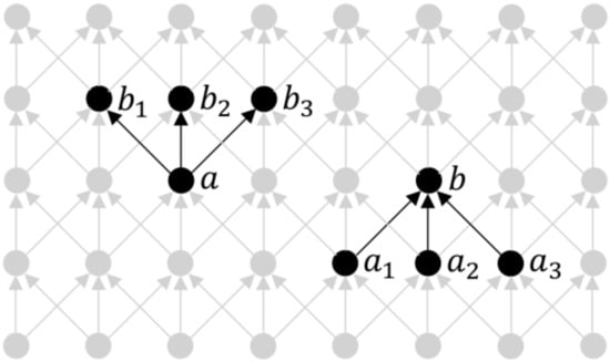
Figure 7.
The conceptual diagram of a directed graph. , , and are successors of . , , and are the predecessors of .
When performing path opening operations, we need to build a directed graph that is based on binary ground fissure images. is a set of points that represents all of the pixel locations in a binary image. A directed graph is defined based on these points through a binary adjacency relation ‘’ (Figure 7), and ‘’ means that there is an edge connecting point to point . In this case, point denotes the successor of point , and point is the predecessor of pixel . These concepts are illustrated in Figure 7. The successor set of each point is expressed as follows:
If is a subset of set , then the successor set of points in can be written as follows:
If there is an adjacency relationship , then the -path with length can be defined as an -tuple , where is the element of the -path. The set of all -paths of length is denoted as . Given a path in , this paper denotes by the set of its elements:
The set of -paths of length in subset of is given as :
All -paths of length in subset are recorded as :
Moreover, represents the path openings along the length of subset . When path openings are used for deionizing, if a path lacks a few pixels, the entire path is divided into two paths so that the length of the divided paths cannot reach the set threshold , eliminating all the pixels comprising the entire path. To reduce the sensitivity of the path morphology to noise, an improved incomplete path opening algorithm [] was proposed. This algorithm allows for some of the pixels along the path to be missing, which greatly enhances the robustness of the path openings. The incomplete path openings eliminate the residual noise in the fissure extraction results by setting thresholds of the path length, and the number of admissible missing pixels, .
The images as they appear after the incomplete path opening process with different are shown in Figure 8; they show that as the path length, increases, the noise is better suppressed but that an excessive leads to the false elimination of short fissures. In addition, is also a key factor during the incomplete path opening process. A smaller led to the loss of some short fissures, while a larger resulted in the images having a considerable amount of noise. Therefore, proper and can achieve balance between fissure preservation and noise suppression. In this article, and were set to 50 and 3, respectively, and were determined according to the actual situation in our study area.
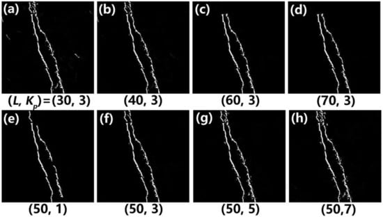
Figure 8.
(a–h) incomplete path opening results under different .
4.4. Validation
The centerlines that were visible in the ground fissure maps were visually interpreted and were used as reference data. Then, the centerline of the automatically extracted result was obtained. Drawing on the previous linear element extraction research [], the confusion matrix (Table 2) between the reference data and the extraction result was obtained to quantify the effects of the ground fissure extraction method used in this paper. According to the corresponding relationship between the fissures in the extraction data and the reference data, the following four items were calculated in the confusion matrix: (1) true positive (TP), (2) true negative (TN), (3) false positive (FP), and (4) false negative (FN).

Table 2.
Confusion matrix used to evaluate the effect of fissure extraction.
There is usually a small amount of deviation between the fissure centerline in the reference data and the extraction data in the actual implementation process. According to the actual width of the fissures, a buffer with a distance of 5 pixels (13.2 cm) was set on both sides of the fissures in reference data, and the parts of the extraction data within the buffer were considered to match the manual reference []. The confusion matrix was used to calculate the user’s accuracy, producer’s accuracy, and Cohen’s kappa coefficient () to evaluate the ground fissure extraction accuracy of our extraction method. In some related works, the user’s accuracy and producer’s accuracy are also called correctness and completeness, respectively [,]. The correctness, completeness, and can be expressed as follows:
where is the number of rows in the confusion matrix, is the element in row and column on the major diagonal of the matrix, and and denote the sum of the elements in row and column respectively.
5. Results
5.1. Accuracy Assessment
Due to the enormous scope of the study area, this paper selected four typical test sites that were 40 m × 40 m in size (Figure 9) and mapped the centerline of the ground fissures by visual interpretation as the ground truth (reference data). The fissure extraction results and ground truth were used to establish a confusion matrix, and the correctness, completeness, and kappa coefficient were calculated as the evaluation indexes to determine the extraction accuracy.
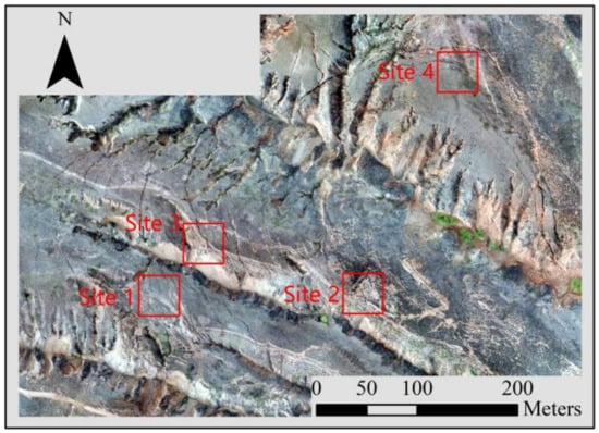
Figure 9.
The four sites selected to test the performance of our method are indicated by the red rectangles.
The extraction results for the ground fissures in the four selected sites are shown in Figure 10. In contrast with the original images, we found that some of the fissures with smaller widths were not successfully extracted, and correspondingly, the producer’s accuracies (completeness) of the four selected areas were between 66.23% and 79% (Table 3). Meanwhile, some elongated shadows that were formed by micro-topography or high-texture ground were identified as fissures, leading to user’s accuracy (correctness) values of 69.03% to 73.22% at the four typical sites (Table 3). According to the existing research, a kappa coefficient greater than 75% represents substantial consistency [], and the kappa coefficients of the four sites were 69.11%, 75.88%, 68.82%, and 67.91%, respectively (Table 3). Therefore, the ground fissure extraction method proposed in this paper showed good performance when tested in the study area.
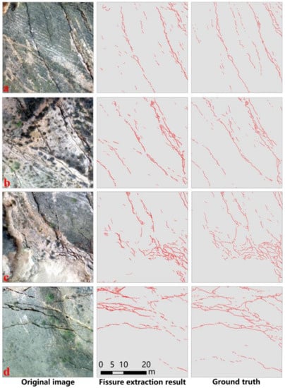
Figure 10.
Original images, ground fissure extraction results, and ground truth obtained by visual interpretation of the four selected sites. (a–d) are the original images of the four selected sites.

Table 3.
Accuracy assessment of fissure extraction at the four selected sites.
5.2. Impacts of
Although the incomplete path opening operation performed well for denoising, the shapes of the ground fissures in the study area were very complex, so a single cannot provide a comprehensive indication of fissure extraction performance. Therefore, we set = (30, 35, 40, 45, 50, 55, 60, 65, 70) and = (1, 2, 3, 4, 5, 6, 7) to generate 63 ground fissure maps at each site and calculated the completeness, correctness, and kappa coefficient to evaluate the impacts of on fissure extraction. The completeness, correctness, and kappa coefficient corresponding to different at different sites are shown in Figure 11. The results indicated that the completeness decreased as the decreased and increased as the increased, while the correctness changed conversely. The combination of a smaller and larger made it easier to obtain higher completeness but resulted in lower correctness. Although there were differences in the completeness and correctness among the four sites, their changing trends were roughly the same. The reasons for this are simple. If a smaller is set, the incomplete path openings would contain more fissure segments that were shorter in length, and a larger would allow this process to detect paths with sufficient length in more fissure segments, thus retaining the most fissure pixels but also greatly increasing the presence of non-fissure pixels in the extraction results, leading to lower correctness. Therefore, the combinations with higher kappa coefficients were mainly located near the diagonal of the coordinate system, but large combinations reduced the kappa coefficients (Figure 11).
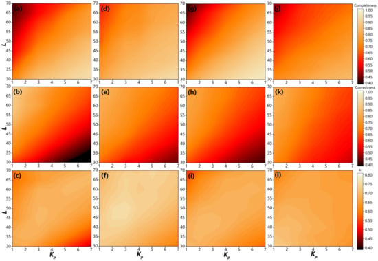
Figure 11.
Contour diagrams obtained by interpolation of completeness, correctness, and kappa coefficient corresponding to different . A lighter color indicates a higher value. (a–l) respectively correspond to completeness, correctness and kappa coefficient of the four selected sites.
According to the impact analysis of , 50 and 3, as employed in Section 4.3, was the combination with high kappa coefficients for all four sites, quantitatively demonstrating that this combination could achieve good ground fissure extraction results in the study area. It is worth noting that and can be set flexibly according to fissure extraction demands or the need to eliminate noise while maintaining the key fissures.
5.3. Ground Fissure Extraction Result
The fissure extraction results in the study area (Figure 12) revealed that when underground mining began in the area, fissures were generated on the ground at the starting position of the working face. As coal mining operations continued to advance, numerous C-shaped fissures were generated inside the working face and spread forward along the advancing direction, which is consistent with the results of field surveys and a theoretical analysis of the impacts of rock strata movement on fissure development [,]. However, the C-shape of the fissures inside the working face was incomplete, and loess gullies interrupted the fissure development process. The extracted fissures were mainly distributed in relatively flat areas, and there were few fissures in the steep slopes of the gullies (Figure 12). In addition, some areas with dense fissures were located at the top of both sides of gullies, and through field investigations, we found that these fissures were formed by landslides on steep slopes that had been disturbed by underground mining (Figure 12a,b). However, the densely distributed fissures in the extraction results of this study were not all real ground fissures. Figure 12c,d shows that noise may be caused by the erroneous extraction of the thin ground erosion gullies and the collapsed soil fragment gaps, which are very similar in shape to real ground fissures.
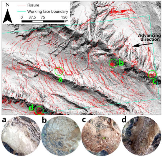
Figure 12.
The extraction results and distribution of ground fissures in the study area. (a–d) Typical areas where the extracted fissures are densely distributed. (a,b) Steep slopes with landslides due to mining disturbance, and there are lots of sliding fissures at the top. (c) Area where massive soil fragments are produced by collapse. (d) Soil erosion area with thin gullies.
6. Discussion
Ground fissure is one of the main disasters caused by underground coal mining; so, it is necessary to develop rapid ground fissure monitoring and extraction technology. In this paper, we have successfully extracted ground fissures from UAV high-resolution images by using an automatic detection algorithm. The results of fissure extraction in the study area indicated that the proposed method can effectively avoid the edge extraction of non-fissure features under complex surface backgrounds. Meanwhile, the ground fissures with different widths and directions in the study area were extracted by using the multiscale Hessian-based enhancement filter. Furthermore, broken fissures cannot be connected simply by morphological operators, which leads to their morphological similarity with noise, but the utilization of incomplete path openings enables our method to distinguish short fissure segments and noise well. In dealing with the challenges in the extraction of ground fissures in mining area, the proposed method has achieved ideal fissure extraction accuracy (Table 3).
Automatic extraction of ground fissures in mining areas is a complicated process, and traditional edge detection operators and image segmentation methods can hardly meet the requirements. To prove this, the Canny operator [] and object-oriented segmentation were used to extract ground fissures at the four selected sites. The object-oriented segmentation was handled in eCognition software (Trimble Germany Gmbh, Munich, Germany), using an appropriate scale parameter to segment images and then using a support vector machine (SVM) to extract ground fissures. The Canny operator is only sensitive to the edge information in the image, and unilateral edges of partial fissures were extracted, as shown in the area marked by shape A in Figure 13a.
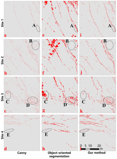
Figure 13.
Fissure extraction results of different methods. (a–d) Results of the Canny operator. (e–h) Results of object-oriented segmentation. (i–l) Results of our method.
In addition, the extraction results of the Canny operator contained numerous non-fissure edges (e.g., the areas marked by shapes B in Figure 13b and C in Figure 13c), and we may not be able to distinguish which fissure the edge belongs to because of the close distance between fissures (e.g., the area marked by shape D in Figure 13c). Therefore, it is also difficult for us to evaluate the extraction accuracy of Canny operator. Although the extraction results of object-oriented segmentation can roughly reflect the shape of fissures (Figure 13e–h), this method mistakenly classified shadows in images as fissures (e.g., the area marked by shape C in Figure 13c). The kappa coefficients of the extracted results of object-oriented segmentation in the four selected sites were 48.84%, 45.77%, 54.74%, and 48.25%, respectively, which were lower than those for our method. The proposed method shows better fissure extraction performance than the Canny operator and object-oriented segmentation (e.g., the ground fissures marked by shape E in Figure 13l).
According to the fissure extraction completeness, less fluctuation was observed (66.23–79.00%) in the ratios of the real fissures at the four typical test sites, mainly because the images with the same resolutions were acquired at the same time and under the same weather conditions. However, the highest detected ratio of 79.00% also revealed that the image resolution (2.64 cm) used in this paper was still unable meet the needs of automatic small fissure extraction. The ground fissures that were detected by the automatic extraction algorithm in this study were typical linear features. Previous research has shown that the image resolution used for extraction is an important factor that affects the accuracy of linear feature extraction [,,]. We randomly selected 360 locations in the study area that had ground fissures and verified whether the fissures in these locations were successfully detected in the extraction results. The results indicated that the detection ratio was 72.22%, which was close to the completeness of the four typical test sites. As shown in Figure 14, fissures can be divided into five categories based on width. All fissures with a width within one pixel were not detected, and the detected ratio of fissures with a width from one pixel to two pixels was only 45.52%. As the fissure width increased, the detection ratio increased rapidly. The detection ratio exceeded 87% when the fissure width was greater than two pixels, and all fissures were detected as long as their width was greater than four pixels. The method proposed in this paper cannot detect ground fissures with a width less than one pixel; however, it can detect fissures with widths greater than two pixels stably. In a study on automatic fissure extraction in the Super-Sauze mudslide, Stumpf et al. [] proposed that lower resolution UAV images do not necessarily correspond to lower fissure extraction accuracy but that the spatial resolution of the image is at least equivalent to the target fissure width. Therefore, in practical applications, we should fully consider the width of ground fissures in mining areas when setting the UAV flight altitude to obtain orthoimages with the required resolution.
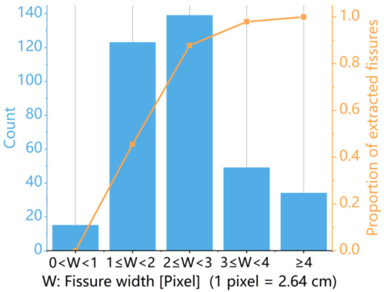
Figure 14.
The number of fissures with different width grades and the proportion of successful extraction.
The correctness of the fissure extraction executed at the four test areas ranged from 70.08% to 82.70%, indicating that noise is contained in the extraction results. Due to the inherent mechanism of our method proposed in this paper, the extraction results have some collapsed soil fragment gaps (Figure 15a), thin surface erosion gullies (Figure 15d), and vegetation texture features (Figure 15g), resulting in a decrease in the fissure extraction accuracy (Figure 15b,e,h). The shapes of these noise sources are very similar to the ground fissures, and their cross-sectional grayscale curves are consistent with the fissures (Figure 15c,f,i). At present, the algorithm proposed in this paper cannot distinguish these noise sources from ground fissures.
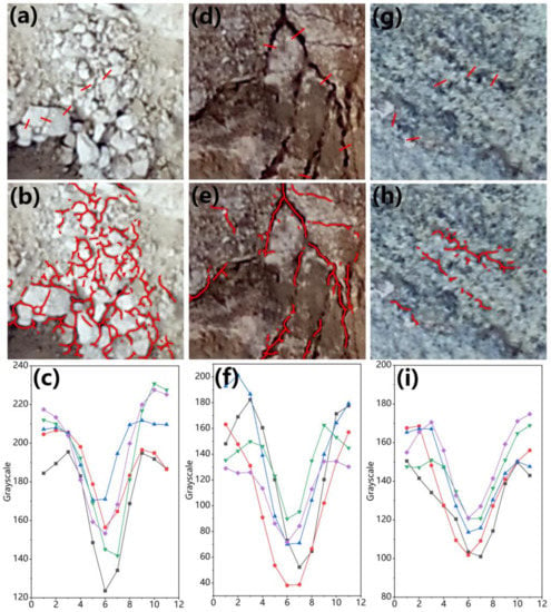
Figure 15.
Examples of the fissure extraction noise source. (a) A collapsed area with soil fragment gaps. (d) A soil erosion area with thin gullies. (g) An area with vegetation texture features similar to ground fissures. (b,e,h) Fissure extraction results of (a,d,g). (c,f,i) Grayscale curves at the red lines in (a,d,g). They represent the grayscale characteristics at the cross-section of the three noise sources.
Meanwhile, the low solar altitude angle leads to a reduction in the fissure extraction accuracy []. Our method actually uses the shadows generated by deep ground fissures to realize automatic extraction. As shown in Figure 16, the noise sources are not as deep as the ground fissures, and when the solar altitude angle is large, the shadow that affects the extraction accuracy cannot be formed. However, in the case of a lower solar altitude angle, the three noise sources are more likely to produce shadows that are falsely extracted as ground fissures. Our UAV images were collected at 16:00 on 21 April 2019, and the corresponding solar altitude angle was 26°45′, which reduced the fissure extraction accuracy. Furthermore, in this study, full sunlight at the surface may decrease the extraction accuracy further [].
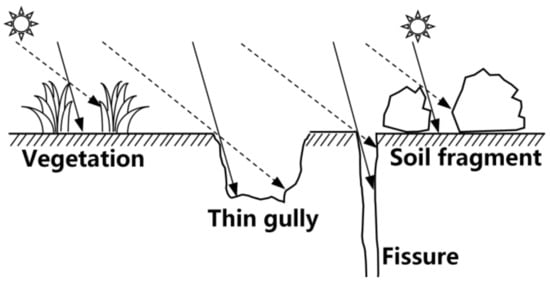
Figure 16.
Shadow changes at a fissure and three noise sources for different solar altitude angles.
Although there was a great deal of noise in the images, the fissure extraction results still reflect the fissure distribution in the study area. However, the distribution characteristics of the extracted fissures are not completely consistent with underground mining theories because of the large slope areas. Through theoretical analysis and numerical simulation, existing research on slope stability has revealed that the slope is simultaneously affected by its own gravity and the additional mining stress that is imparted upon it during ground movement and deformation processes [,]. Disturbed by underground coal mining, slippage occurs in areas with large slopes, accompanied by the formation of sliding fissures []. Meanwhile, the generation of ground fissures on the slope increases horizontal displacement along the downslope direction [], further deteriorating the stability of the slope and leading to landslides. A large number of landslides in the large slope area destroyed the fissures, and only the portion of the fissure in the top area of the slope is retained, resulting in fewer fissures being detected in large slope areas in the extraction results.
After the long-term improvement and innovation of image processing and extraction algorithms, the accuracy of the automatic extraction of linear elements has continued to improve. In some studies on the automatic extraction of road fissures, the correctness and completeness of the extraction results were both more than 70% [,]. Al-Rawabdeh et al. [] obtained extraction results of 82.24% and 75.0% for correctness and completeness for the automatic extraction of landslide features. The fissure extraction accuracy in this paper may not reach the same level as the one obtained in other linear element extraction studies; however, it still solves the main problem related to the automatic extraction of ground fissures in coal mining subsidence to a certain extent. Meanwhile, the proposed method was also compared with the existing research on ground fissure extraction. Zhao et al. [] used classical edge detection operators to extract fissures from UAV thermal infrared images, and we analyzed some defects of this type of operators in ground fissure extraction. The automatic extraction algorithm proposed by Jia et al. [] has a fixed-scale so, its adaptiveness to fissures with different widths needs further research. Moreover, denoising according to the fissure candidate area would lead to the false removal of some short fissure segments. Zhang et al. [] divided the UAV image into four datasets according to the characteristics of background information: bright ground, dark ground, withered vegetation, and green vegetation, and then extracted ground fissures by machine learning. However, in general, the types of features in mining areas are more than the above categories. Therefore, it is noted that our proposed method has certain advantages in extracting ground fissures from complex background information.
7. Conclusions
In this paper, an image processing chain was developed to extract ground fissures through high-resolution UAV images, and it was tested on the working face of the Ningtiaota Coal Mine in order to realize the automatic extraction of ground fissures caused by coal mining subsidence. In our method, the multiscale Hessian-based enhancement filter was used to enhance the ground fissure information, and a simple single-thresholding operation was then employed to generate a binary ground fissure map; the incomplete path openings method was applied to eliminate the noise in the fissure extraction results. The fissure extraction results were displayed with the fissure centerlines.
Verified by manual visual interpretation, the completeness, correctness, and kappa coefficient of the fissure extraction results at the four selected test sites were 66.23–79.00%, 69.03–73.22%, and 67.91–75.88%, respectively. The path length and the number of admissible missing pixels in the incomplete path openings had a significant influence on the accuracy of the extraction results, and the of (50, 3) that was used in this study was found to be reasonable. Our research indicates that image resolution is the key factor for successful fissure detection, and the main sources of fissure extraction noise are collapsed soil fragments, thin erosion gullies, and vegetation textures. In addition, the solar altitude angle and illumination conditions also influence extraction accuracy. The fissure distribution in the study area was simultaneously affected by underground mining and topography.
This study verifies the feasibility of using high-resolution UAV images to automatically extract ground fissures caused by coal mining subsidence. Our method will greatly improve the monitoring efficiency of ground fissures and provide more valuable data for ecological restoration in mining areas.
Author Contributions
Conceptualization, K.Y. and Z.H.; data curation, Y.L. (Yusheng Liang); formal analysis, K.Y. funding acquisition, Z.H.; investigation, K.Y., Y.L. (Yusheng Liang), Y.F., D.Y., J.G., G.L. and Y.L. (Yong Li); methodology, K.Y.; project administration, Z.H.; resources, Z.H.; software, K.Y. and Y.L. (Yusheng Liang); supervision, D.Y.; validation, K.Y. and Y.L. (Yusheng Liang); visualization, J.G.; writing—original draft, K.Y.; writing—review and editing, Z.H. and Y.L. (Yusheng Liang). All authors have read and agreed to the published version of the manuscript.
Funding
This research was funded by National Natural Science Foundation of China (grant number 41801380) and by the Research and Demonstration of Key Technology for Water Resources Protection and Utilization and Ecological Reconstruction in Coal Mining area of Northern Shaanxi (grant number 2018SMHKJ-A-J-03).
Institutional Review Board Statement
Not applicable.
Informed Consent Statement
Not applicable.
Data Availability Statement
The data presented in this study are available from the corresponding author upon request.
Acknowledgments
We sincerely thank the Shaanxi Coal and Chemical Industry Group for providing the underground coal mining data for this study and the above funds for supporting this research as well as the editors and reviewers for their comments and suggestions.
Conflicts of Interest
The authors declare no conflict of interest.
References
- IEA. Key World Energy Statistics 2021; IEA: Paris, France, 2021. [Google Scholar]
- Hu, Z.Q.; Wang, X.J.; He, A.M. Distribution characteristic and development rules of ground fissures due to coal mining in windy and sandy region. J. China Coal Soc. 2014, 39, 11–18. [Google Scholar] [CrossRef]
- Xu, C.; Ma, S.; Zhang, H.; Wang, R.; Guan, Z. Effect of cracks on soil characteristics and crop growth in subsided coal mining areas. Chin. J. Eco-Agric. 2015, 23, 597–604. [Google Scholar] [CrossRef]
- Kong, J.L.; Xian, T.; Yang, J.; Chen, L.; Yang, X.T. Monitoring soil moisture in a coal mining area with multi-phase Landsat images. In Proceedings of the ISPRS—International Archives of the Photogrammetry, Remote Sensing and Spatial Information Sciences, Prague, Czech Republic, 12–19 July 2016; pp. 537–542. [Google Scholar]
- Bi, Y.; Zhang, J.; Song, Z.; Wang, Z.; Qiu, L.; Hu, J.; Gong, Y. Arbuscular mycorrhizal fungi alleviate root damage stress induced by simulated coal mining subsidence ground fissures. Sci. Total Environ. 2019, 652, 398–405. [Google Scholar] [CrossRef] [PubMed]
- Zhang, J.; Bi, Y.; Song, Z.; Xiao, L.; Christie, P. Arbuscular mycorrhizal fungi alter root and foliar responses to fissure-induced root damage stress. Ecol. Indic. 2021, 127, 107800. [Google Scholar] [CrossRef]
- Zhang, J.; Yang, M.; Zhang, F.; Tang, Y.; Wang, X.; Wang, Y. Revealing soil erosion characteristics using deposited sediment sources in a complex small catchment in the wind-water erosion crisscross region of the Chinese Loess Plateau. Geoderma 2020, 379, 114634. [Google Scholar] [CrossRef]
- Yang, D.; Qiu, H.; Ma, S.; Liu, Z.; Du, C.; Zhu, Y.; Cao, M. Slow surface subsidence and its impact on shallow loess landslides in a coal mining area. Catena 2022, 209, 105830. [Google Scholar] [CrossRef]
- Fan, L.M.; Zhang, X.T.; Xiang, M.X.; Zhang, H.Q.; Shen, T.; Lin, P.X. Characteristics of ground fissure development in high intensity mining area of shallow seam in Yushenfu coal field. J. China Coal Soc. 2015, 40, 1442–1447. [Google Scholar] [CrossRef]
- Li, L.; Wu, K.; Hu, Z.; Xu, Y.; Zhou, D. Analysis of developmental features and causes of the ground cracks induced by oversized working face mining in an aeolian sand area. Environ. Earth Sci. 2017, 76, 135. [Google Scholar] [CrossRef]
- Zhou, D.W.; Wu, K.; Bai, Z.H.; Hu, Z.Q.; Li, L.; Xu, Y.K.; Diao, X.P. Formation and development mechanism of ground crack caused by coal mining: Effects of overlying key strata. Bull. Eng. Geol. Environ. 2019, 78, 1025–1044. [Google Scholar] [CrossRef]
- Liu, H.; Deng, K.Z.; Zhu, X.J.; Jiang, C.L. Effects of mining speed on the developmental features of mining-induced ground fissures. Bull. Eng. Geol. Environ. 2019, 78, 6297–6309. [Google Scholar] [CrossRef]
- Fu, Y.; Shang, J.; Hu, Z.; Li, P.; Yang, K.; Chen, C.; Guo, J.; Yuan, D. Ground fracture development and surface fracture evolution in N00 method shallowly buried thick coal seam mining in an arid windy and sandy area: A case study of the Ningtiaota Mine (China). Energies 2021, 14, 7712. [Google Scholar] [CrossRef]
- Yang, X.; Wen, G.; Dai, L.; Sun, H.; Li, X. Ground subsidence and surface cracks evolution from shallow-buried close-distance multi-seam mining: A case study in Bulianta Coal Mine. Rock Mech. Rock Eng. 2019, 52, 2835–2852. [Google Scholar] [CrossRef]
- Colomina, I.; Molina, P. Unmanned aerial systems for photogrammetry and remote sensing: A review. ISPRS J. Photogramm. Remote Sens. 2014, 92, 79–97. [Google Scholar] [CrossRef] [Green Version]
- Stumpf, A.; Malet, J.-P.; Kerle, N.; Niethammer, U.; Rothmund, S. Image-based mapping of surface fissures for the investigation of landslide dynamics. Geomorphology 2013, 186, 12–27. [Google Scholar] [CrossRef] [Green Version]
- Perry, B.J.; Guo, Y.; Atadero, R.; van de Lindt, J.W. Streamlined bridge inspection system utilizing unmanned aerial vehicles (UAVs) and machine learning. Measurement 2020, 164, 108048. [Google Scholar] [CrossRef]
- Zhang, L.; Xu, W.C.; Zhu, L.L.; Yuan, X.Z.; Zhang, C. Study on pavement defect detection based on image processing utilizing UAV. J. Phys. Conf. Ser. 2019, 1168, 042011. [Google Scholar] [CrossRef]
- Zollini, S.; Alicandro, M.; Dominici, D.; Quaresima, R.; Giallonardo, M. UAV photogrammetry for concrete bridge inspection using object-based image analysis (OBIA). Remote Sens. 2020, 12, 3180. [Google Scholar] [CrossRef]
- Al-Rawabdeh, A.; He, F.N.; Moussa, A.; El-Sheimy, N.; Habib, A. Using an unmanned aerial vehicle-based digital imaging system to derive a 3D point cloud for landslide scarp recognition. Remote Sens. 2016, 8, 95. [Google Scholar] [CrossRef] [Green Version]
- Bhowmick, S.; Nagarajaiah, S.; Veeraraghavan, A. Vision and Deep Learning-Based Algorithms to Detect and Quantify Cracks on Concrete Surfaces from UAV Videos. Sensors 2020, 20, 6299. [Google Scholar] [CrossRef]
- Zhang, F.; Hu, Z.; Fu, Y.; Yang, K.; Wu, Q.; Feng, Z. A new identification method for surface cracks from UAV images based on machine learning in coal mining areas. Remote Sens. 2020, 12, 1571. [Google Scholar] [CrossRef]
- Jia, H.; Wei, B.; Liu, G.; Zhang, R.; Yu, B.; Wu, S. A semi-automatic method for extracting small ground fissures from loess areas using unmanned aerial vehicle images. Remote Sens. 2021, 13, 1784. [Google Scholar] [CrossRef]
- Zhao, Y.; Sun, B.; Liu, S.; Zhang, C.; He, X.; Xu, D.; Tang, W. Identification of mining induced ground fissures using UAV and infrared thermal imager: Temperature variation and fissure evolution. ISPRS J. Photogramm. Remote Sens. 2021, 180, 45–64. [Google Scholar] [CrossRef]
- Chen, C.; Hu, Z. Research advances in formation mechanism of ground crack due to coal mining subsidence in China. J. China Coal Soc. 2018, 43, 810–823. [Google Scholar] [CrossRef]
- Yu, X.; Li, B.; Li, R.; Duan, W.; Liu, P. Analysis of mining damage in huge thick collapsible loess of western China. J. China Univ. Min. Technol. 2008, 37, 43–47. [Google Scholar]
- Kang, J. Analysis of effect of fissures caused by underground mining on ground movement and deformation. Chin. J. Rock Mech. Eng. 2008, 27, 59–64. [Google Scholar]
- Liu, H.; He, C.G.; Deng, K.Z.; Bian, Z.F.; Fan, H.D.; Lei, S.G.; Zhang, A.B. Analysis of forming mechanism of collapsing ground fissure caused by mining. J. Min. Saf. Eng. 2013, 30, 380–384. [Google Scholar]
- Meinen, B.U.; Robinson, D.T. Mapping erosion and deposition in an agricultural landscape: Optimization of UAV image acquisition schemes for SfM-MVS. Remote Sens. Environ. 2020, 239, 111666. [Google Scholar] [CrossRef]
- Canny, J. A computational approach to edge-detection. IEEE Trans. Pattern Anal. Mach. Intell. 1986, 8, 679–698. [Google Scholar] [CrossRef]
- Marr, D.; Hildreth, E. Theory of edge detection. Proc. R. Soc. Lond. Ser. B Biol. Sci. 1980, 207, 187–217. [Google Scholar] [CrossRef]
- Wang, C.L.; Oda, M.; Hayashi, Y.; Yoshino, Y.; Yamamoto, T.; Frangi, A.F.; Mori, K. Tensor-cut: A tensor-based graph-cut blood vessel segmentation method and its application to renal artery segmentation. Med. Image Anal. 2020, 60, 101623. [Google Scholar] [CrossRef]
- Lampert, T.A.; O’Keefe, S.E.M. A detailed investigation into low-level feature detection in spectrogram images. Pattern Recognit. 2011, 44, 2076–2092. [Google Scholar] [CrossRef] [Green Version]
- Frangi, A.F.; Niessen, W.J.; Vincken, K.L.; Viergever, M.A. Multiscale vessel enhancement filtering. Lect. Notes Comput. Sci. 1998, 1496, 130–137. [Google Scholar] [CrossRef] [Green Version]
- Sato, Y.; Nakajima, S.; Shiraga, N.; Atsumi, H.; Yoshida, S.; Koller, T.; Gerig, G.; Kikinis, R. Three-dimensional multi-scale line filter for segmentation and visualization of curvilinear structures in medical images. Med. Image Anal. 1998, 2, 143–168. [Google Scholar] [CrossRef]
- Heijmans, H. Path openings and closings. J. Math. Imaging Vis. 2005, 22, 107–119. [Google Scholar] [CrossRef]
- Talbot, H.; Appleton, B. Efficient complete and incomplete path openings and closings. Image Vis. Comput. 2007, 25, 416–425. [Google Scholar] [CrossRef]
- Yang, J.Z.; Huang, M.X.; Fu, J.; Lou, C.H.; Feng, C.L. Frangi based multi-scale level sets for retinal vascular segmentation. Comput. Methods Programs Biomed. 2020, 197, 105752. [Google Scholar] [CrossRef]
- Chen, H.Y.; Zhao, H.F.; Han, D.; Liu, W.P.; Chen, P.; Liu, K. Structure-aware-based crack defect detection for multicrystalline solar cells. Measurement 2020, 151, 107170. [Google Scholar] [CrossRef]
- Ghanta, S.; Shamsabadi, S.S.; Dy, J.; Wang, M.; Birken, R. A Hessian-based methodology for automatic surface crack detection and classification from pavement images. In Proceedings of the Structural Health Monitoring and Inspection of Advanced Materials, Aerospace, and Civil Infrastructure, San Diego, CA, USA, 9–12 March 2015; pp. 94371Z-1–94371Z-11. [Google Scholar]
- Tuermer, S.; Kurz, F.; Reinartz, P.; Stilla, U. Airborne vehicle detection in dense urban areas using HoG features and disparity maps. IEEE J. Sel. Top. Appl. Earth Observ. Remote Sens. 2013, 6, 2327–2337. [Google Scholar] [CrossRef]
- Zhan, Q.M.; Molenaar, M.; Tempfli, K.; Shi, W.Z. Quality assessment for geo-spatial objects derived from remotely sensed data. Int. J. Remote Sens. 2005, 26, 2953–2974. [Google Scholar] [CrossRef]
- Wang, C.L.; Zhang, C.S.; Zhao, X.D.; Liao, L.; Zhang, S.L. Dynamic structural evolution of overlying strata during shallow coal seam longwall mining. Int. J. Rock Mech. Min. Sci. 2018, 103, 20–32. [Google Scholar] [CrossRef]
- Zhang, J.; Zhao, Y.; Abbott, A.L.; Wynne, R.H.; Hu, Z.; Zou, Y.; Tian, S. Automated mapping of typical cropland strips in the North China Plain using small unmanned aircraft systems (sUAS) photogrammetry. Remote Sens. 2019, 11, 2343. [Google Scholar] [CrossRef] [Green Version]
- Wang, Z.; Liu, J.; Li, J.; Meng, Y.; Pokhrel, Y.; Zhang, H. Basin-scale high-resolution extraction of drainage networks using 10-m Sentinel-2 imagery. Remote Sens. Environ. 2021, 255, 112281. [Google Scholar] [CrossRef]
- Yang, K.; Smith, L.C.; Sole, A.; Livingstone, S.J.; Cheng, X.; Chen, Z.; Li, M. Supraglacial rivers on the northwest Greenland Ice Sheet, Devon Ice Cap, and Barnes Ice Cap mapped using Sentinel-2 imagery. Int. J. Appl. Earth Obs. Geoinf. 2019, 78, 1–13. [Google Scholar] [CrossRef] [Green Version]
- Liu, H.; Deng, K.; Lei, S.; Bian, Z. Mechanism of formation of sliding ground fissure in loess hilly areas caused by underground mining. Int. J. Min. Sci. Technol. 2015, 25, 553–558. [Google Scholar] [CrossRef]
- Fathi Salmi, E.; Nazem, M.; Karakus, M. Numerical analysis of a large landslide induced by coal mining subsidence. Eng. Geol. 2017, 217, 141–152. [Google Scholar] [CrossRef]
- Zhang, A.; Wang, K.C.P.; Li, B.; Yang, E.; Dai, X.; Peng, Y.; Fei, Y.; Liu, Y.; Li, J.Q.; Chen, C. Automated pixel-level pavement crack detection on 3D asphalt surfaces using a deep-learning network. Comput.-Aided Civ. Infrastruct. Eng. 2017, 32, 805–819. [Google Scholar] [CrossRef]
- Bang, S.; Park, S.; Kim, H.; Kim, H. Encoder–decoder network for pixel-level road crack detection in black-box images. Comput.-Aided Civ. Infrastruct. Eng. 2019, 34, 713–727. [Google Scholar] [CrossRef]
Publisher’s Note: MDPI stays neutral with regard to jurisdictional claims in published maps and institutional affiliations. |
© 2022 by the authors. Licensee MDPI, Basel, Switzerland. This article is an open access article distributed under the terms and conditions of the Creative Commons Attribution (CC BY) license (https://creativecommons.org/licenses/by/4.0/).