1. Introduction
Passive bistatic radar (PBR) itself does not emit an electromagnetic signal but uses the third-party non-cooperative emitter as the illuminator of opportunity (IoO) for target detection and tracking [
1,
2]. Compared with the traditional active radar, it has the following advantages: (1) No need to build transmitter, low cost, and small size; (2) No specific frequency distribution and no electromagnetic pollution; (3) The radiation sources are widely distributed, which is convenient for information fusion, radar networking and multi-station positioning. Therefore, in recent years, PBR has attracted extensive attention [
3,
4,
5,
6]. At present, the feasibility and detection performance of different civil signals, including frequency modulation (FM) broadcast signal [
7,
8], digital television broadcast (DVB-T) [
9,
10], China mobile multimedia broadcasting (CMMB) [
11], Global Navigation Satellite System (GNSS) [
12], long-term evolution (LTE) signal [
13,
14,
15] and so on, have been studied as IoO. Moreover, many research results have been obtained.
In PBR, the direction of arrival (DOA) is an important parameter to be estimated [
7,
16]. For example, people can locate a target through the estimated target bistatic distance and DOA. In a passive multi-static radar, DOA can help to reduce the false associations between the targets and measurements [
17,
18]. DOA estimation in PBR has been intensively studied and many methods have been proposed [
19,
20,
21]. For example, in [
22], using a pair of Yagi–Uda antennas, a DOA estimation method based on interfere metric is proposed. In [
23], the ADCOCK antenna is used as a PBR receiving antenna for DOA estimation, which can realize a 360° unambiguous angle measurement of the target. Subsequently, in [
24], an improved DOA estimation has been proposed, which can realize DOA estimation when the reference signal is mixed with target echo. In [
19], a robust target DOA estimation is discussed by accurately estimating the actual antenna steering vector. In [
20], a DOA estimation method based on the joint processing of nonuniform linear arrays and multi-channel is studied, which can achieve high-precision non-ambiguous angle measurements. In [
18], a deep learning-based method for DOA estimation in PBR is proposed. In [
25], a multi-target super-resolution DOA estimation method is proposed and discussed.
In order to estimate target DOA, it is necessary to detect the target first in PBR. However, unlike the traditional active radar, the weak target echo in PBR is usually embedded in the background of strong direct and multipath interferences (DMI) due to the bistatic and continuous wave transmitting and receiving system [
26]. Therefore, in the traditional target detection and DOA estimation method of PBR, the clutter cancellation method should be first used to suppress DMI. Following this, the range-Doppler cross-correlation (RDCC) is conducted to further increase the target signal to clutter plus noise ratio (SCNR). Assuming that all strong DMI are suppressed effectively, the target echo is detected. Finally, using the data corresponding to the target range and doppler unit, the target DOA is estimated according to the phase differences of the RDCC results corresponding to different antenna array elements [
19,
20,
21]. In the traditional PBR based on FM and analog TV, which adopt the frequency division multiple access (FDMA) technique, the interferences mainly include the DMI from the base station that is used as the IoO (BS-IoO) [
7,
22]. At present, many clutter cancellation methods [
26] have been proposed, such as least mean square (LMS) [
27], extended cancellation algorithm (ECA) [
28], sub-carrier domain algorithm [
29,
30], etc. These methods have been proved to be effective in suppressing DMI from BS-IoO [
26,
31]. However, with the development of radio technologies such as communication, navigation and radar, frequency reuse is becoming more and more common, resulting in more and more serious mutual interference between different radios. This means that PBR will suffer from interferences not only from BS-IoO, but also from the base station with co-frequency or adjacent frequency (BS-CF/AF) [
32,
33]. For example, in mobile communication systems (including 2G, 3G, and 4G), due to the cellular network site layout structure and dense site layout, the transmitted signals of different base stations cannot be distinguished by frequency. Therefore, the echo antenna in mobile communication signal-based PBR will receive DMI sent by multiple BS-CF/AF (in this paper, the DMI from BS-CF/AF is called co-channel interference). Since different base stations transmit different signals in the mobile communication systems, it is impossible to eliminate the interferences of BS-CF/AF using the reference signal of BS-IoO [
15,
34,
35]. At the same time, for densely distributed Wi-Fi signal with only 2.4 GHz and 5 GHz frequency bands, and digital terrestrial multimedia broadcasting (DTMB) stations working in the same frequency band with similar space but different broadcast contents, when these signal sources are used as IoO for target detection, there will also be residual interferences after clutter cancelation [
33]. When there are strong interferences surplus, the preconditions of the traditional method in [
17,
18,
19,
20,
21,
22,
23,
24] will no longer be met (because the SCNR of target is very low). Therefore, its performance will be seriously degraded. In order to suppress these residual interferences, adaptive digital beamforming (ADBF) is usually used [
35,
36]. However, the DOA estimation performance of ADBF is related to the 3 dB half beam width of the antenna when all spatial degrees of freedom are used to suppress residual interferences. Therefore, in order to obtain good DOA estimation performance, high-cost large-scale array antenna should be used [
36].
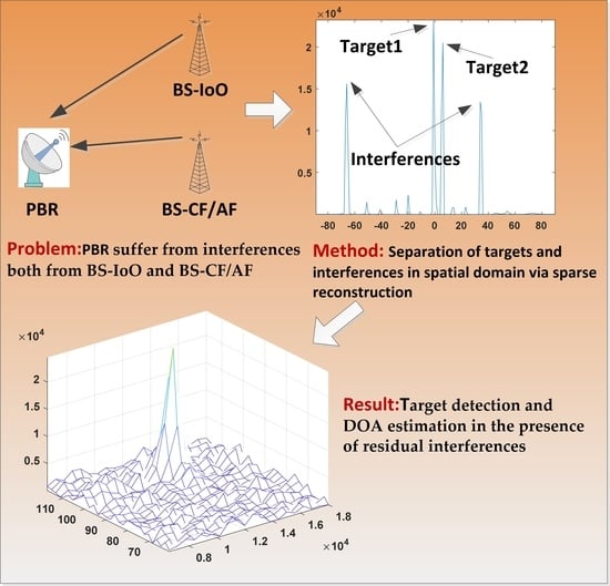
It is necessary to find a new method to realize both target detection and accurate DOA estimation for PBR in the presence of residual interferences. However, the target echoes in PBR are usually very weak. In order to improve SCNR, RDCC should be carried out first. Because there is only one snapshot data after RDCC, it is difficult to use traditional spatial spectrum estimation algorithms such as MUSIC and ESPRIT. Moreover, the compressed sensing sparse reconstruction algorithm can realize spatial spectrum estimation in the case of single snapshot data, which is very suitable for PBR. Therefore, in this paper, a novel target detection and DOA estimation method in PBR based on compressed sensing sparse reconstruction is proposed. In this method, compressed sensing sparse reconstruction is introduced to process the signal after clutter cancellation. The processing flow of the proposed method is as follows. Firstly, clutter cancellation algorithm is used to suppress the interferences from BS-IoO. Secondly, RDCC is conducted to further increase SCNR. Thirdly, the azimuth sparse reconstruction is performed in each range-Doppler unit. Finally, after rearranging the sparse reconstruction results, target detection and DOA estimation are carried out. Compared with the traditional target detection and DOA estimation methods, the proposed method has the following advantages: (1) Considering that the target echo and residual interferences come from different direction, the compressed sensing sparse reconstruction algorithm can separate residual interferences and target echo in spatial domain. Therefore, different from the traditional DOA estimation method based on phase interference principle [
19,
20,
21], the influence of residual interferences on target detection and DOA estimation can be eliminated using the proposed method; (2) Compressed sensing sparse reconstruction algorithm is essentially a super-resolution estimation algorithm [
37,
38]. Therefore, in the process of target detection, it can obtain better anti-mainlobe interferences and performance than traditional ADBF, and in the process of target DOA estimation, it can achieve high-resolution target DOA estimation. Therefore, the proposed method can not only achieve target detection and DOA estimation in the presence of residual interferences, but also better anti-mainlobe interference and high-resolution DOA estimation performance. The simulation and experimental results show that the proposed algorithm has a good level of performance.
The organizational structure of this paper is as follows.
Section 2 describes the signal model.
Section 3 elaborates on the proposed target detection and DOA estimation algorithm based on compressed sensing sparse reconstruction.
Section 4 and
Section 5 demonstrate the numerical simulations and experimental data processing. Finally,
Section 6 draws a conclusion.
2. Signal Model
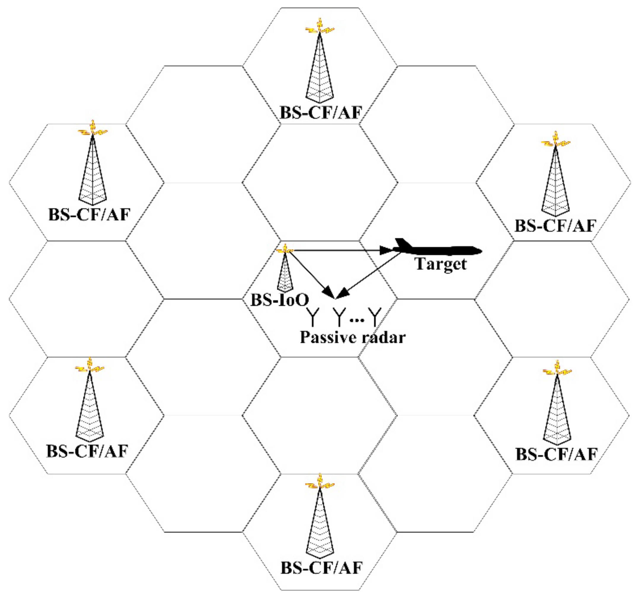
In this paper the global system for mobile communication (GSM) signal is consider as IoO for target detection and tracking.
Figure 1 shows the schematic diagram of radar target detection structure for GSM-based PBR. As can be seen from
Figure 1, due to the cellular network site layout structure and dense site layout, the received signal of the GSM-based PBR includes the signal reflected by the moving target and interferences from both BS-IoO and BS-CF/AF.
When a uniform linear antenna array with M elements is exploited, the received signal of each array antenna element can be represented as:
where:
is the complex envelope of the
k-th DMI from BS-IoO,
is the complex envelope of the
h-th co-channel interference (DMI from BS-CF/AF),
is the complex envelope of the
c-th target echo.
is the DOA of the k-th DMI from BS-IoO, is the DOA of the h-th co-channel interference, is the DOA of the c-th target echo.
is the total number of interferences from BS-IoO, is the total number of co-channel interferences, is the number of target echoes.
is thermal noise in the m-th array element, N is the total number of the signal samples, d is the distance between the adjacent array elements, is the signal wavelength. In this paper d is set as unless otherwise specified.
As can be seen from Equation (1) and previous analysis, with the development of cognitive radio technology, electromagnetic spectrum reuse will become more and more common. At the same time, restricted by the signal transmission characteristics of some radiation sources (such as the cellular network communication structure of mobile communication system), the echo antenna of PBR will receive the interferences not only from BS-IoO but also from BS-CF/AF. After using clutter cancellation algorithm to suppress the interferences from BS-IoO, the residual co-channel interferences will still seriously affect target detection and DOA estimation. In the following, we will introduce a compressed sensing sparse reconstruction method to process the signal after clutter cancellation, which can realize target detection and DOA estimation in the presence of interference residue.
3. Algorithm Description
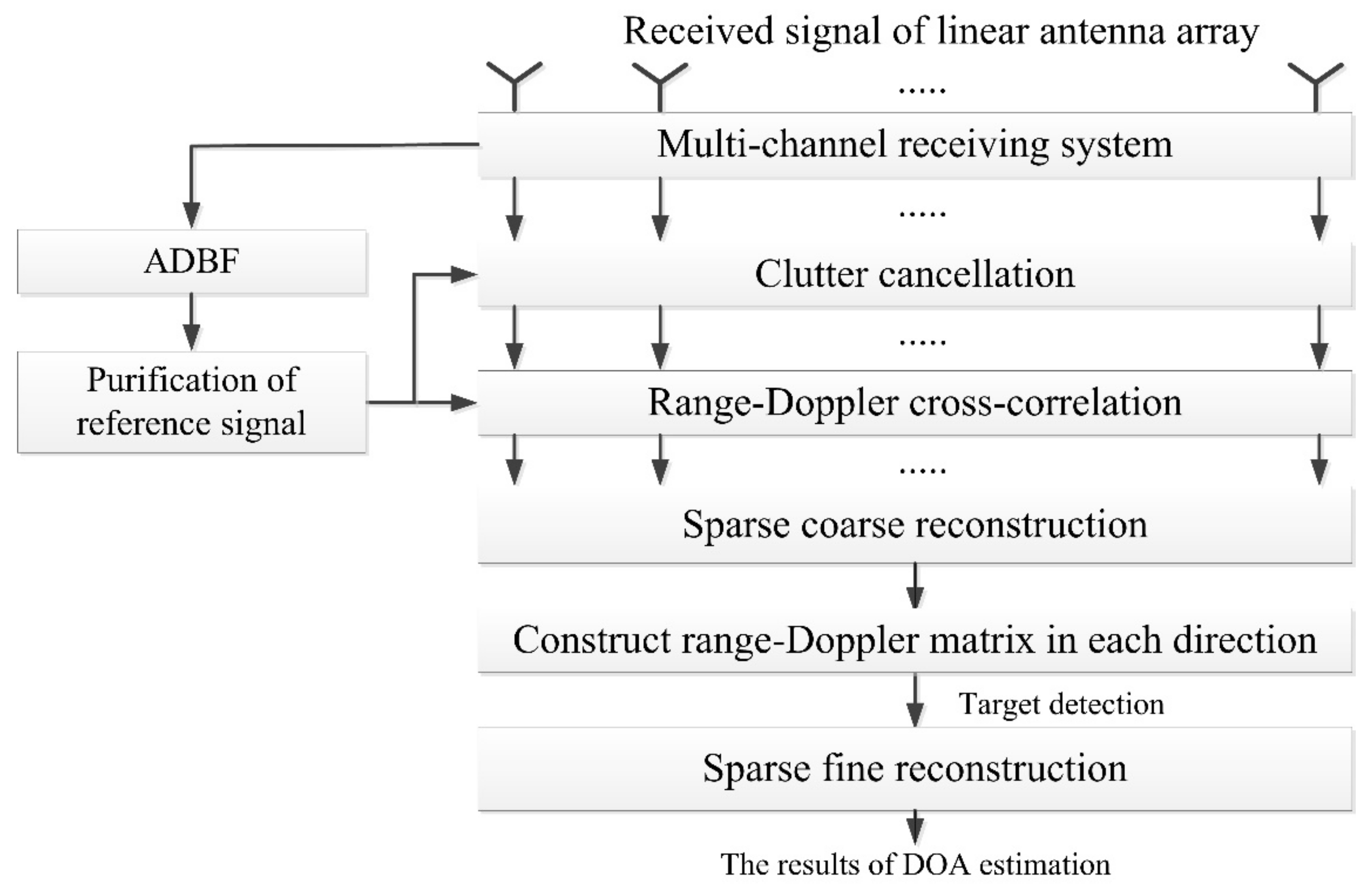
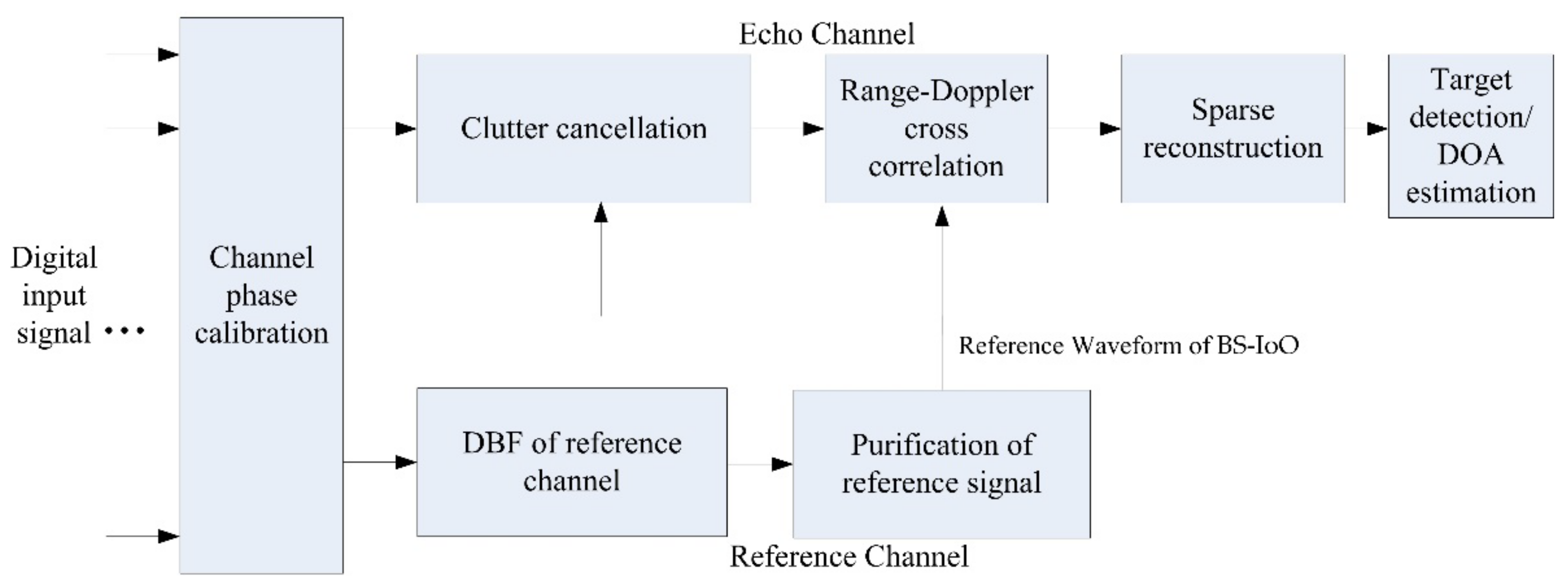
The proposed target detection and DOA estimation method based on compressed sensing sparse reconstruction is shown in
Figure 2. It can be seen from
Figure 2 that the proposed method in this paper mainly includes the following steps:
Clutter cancellation: Firstly, using the reference signal of BS-IoO obtained by digital beamforming (DBF) and purification, the DMI from BS-IoO in each channel is suppressed by clutter cancellation algorithms such as ECA-B.
Range-Doppler cross-correlation (RDCC): RDCC between the reference signal of BS-IoO and the cancelled signal is conducted to improve the SNR of targets. Additionally, since the residual co-channel interferences are not related to the reference signal of BS-IoO, the target signal to clutter ratio (SCR) can also be greatly improved. Therefore, the impact of residual interferences (mainly weak interferences) on target detection and DOA estimation can be reduced.
Sparse coarse reconstruction of each range-Doppler unit in Azimuth: After RDCC, the azimuth sparse coarse reconstruction is performed in each range-Doppler unit to obtain the signal energy in all directions. Considering that the target echo and residual interferences come from a different direction, the residual interferences and target echoes can be separated in spatial domain. Then the influence of residual interferences on target detection and DOA estimation can be eliminated.
Construct range-Dopplermatrix in each direction and target detection: After sparse reconstruction, the results in the same direction are arranged together to form a new range-Doppler two-dimensional matrix. Then the target echoes in different direction are detected, and the coarse estimation results of target DOA can be obtained.
Sparse fine reconstruction of target range-Doppler unit in azimuth: Accurate DOA estimation results are obtained by fine azimuth reconstruction of detected target range-Doppler unit.
The steps of the algorithm are described in detail below.
3.1. Clutter Cancellation and Range-Doppler Cross-Correlation (RDCC)
As seen in
Figure 2, firstly, the reference signal of BS-IoO is obtained by DBF and purification. It can be written as follows:
where,
represents the direct signal of BS-IoO,
represents the complex amplitude,
represents the combination of noise and other DMI from both BS-IoO and BS-CF/AF. It should be noted that the PBR system is usually located within the scope of BS-IoO service. Therefore, in order to meet the need of communication services, the power of direct signal of BS-IoO received by each array element is much larger than the other signals. Then after DBF pointing to BS-IoO and purification, the reference signal
of BS-IoO with high SNR can be obtained.
After acquiring the reference signal
, strong DMI corresponding to BS-IoO in each channel is suppressed using clutter cancellation algorithms such as ECA-B. The cancelled signal of each channel can be written as follows:
where
is the cancelled signal of
m-th th channel (i.e., the
m-th array element),
is the combination of the noise and residual weak DMI from BS-IoO. Then, RDCC between the reference signal of BS-IoO and the cancelled signal is conducted.
where
and
are the delay unit and Doppler unit respectively. * represent conjugation.
After RDCC, Equation (3) can be expressed as the following form:
where:
represents the complex envelope of cross-correlation between residual co-channel interferences and the reference signal of BS-IoO;
represents the complex envelope of cross-correlation between target echoes and the reference signal of BS-IoO;
represents the complex envelope of cross-correlation between thermal noise (including residual weak DMI from BS-IoO) and the reference signal of BS-IoO:
Write Equation (5) in vector form as:
It is easily to see that the signal in Equation (6) can be regarded as a linear combination of target echoes and residual interferences. Moreover, after RDCC, the target SCNR will be greatly improved. For example, in GSM-based PBR, when the signal bandwidth is 80 kHz and the accumulation time is set as 0.5 s, the cross-correlation gain will reach 43 dB (considering an accumulated gain loss of 3 dB). Therefore, the data in each range-Doppler unit can be regarded as only composed of some residual strong interference sidelobes or the mainlobe of the target echo corresponding to this unit (the noise and sidelobe of weak interferences can be regarded as noise uniformly). In the following, we propose to reconstruct the cancelled signal in Equation (6) using the sparse reconstruction method to eliminate the influence of residual interferences on target detection and DOA estimation.
3.2. Sparse Coarse Reconstruction of Each Range-Doppler Unit in Azimuth
In the traditional method based on the principle of phase interference, target echo is detected using the signal
in Equation (5). Following this, the target DOA is estimated by using the data of detected range and Doppler unit. However, when there are strong interferences surplus, it is difficult for the traditional method to detect target echo. In order to eliminate the influence of residual interference on target detection and DOA estimation, the sparse reconstruction algorithm proposed in [
39] is introduced to reconstruct
in azimuth. The basic idea of this algorithm is to solve the following L1 norm minimum optimization problem:
is the observation matrix, which is composed of steering vectors in all directions (the linear array corresponds to −90° to 90°). It can be written as follows:
where
is the number of grids divided by azimuth space −90~90°. From Equation (8), it can be seen that in sparse coarse reconstruction, the signals in all direction are reconstructed.
is the signal vector to be solved. It represents the complex envelope of in all directions, including the complex envelope of the target echoes and the complex envelope of the residual interferences. This is as well as the signal dimension of is .
is a constant, represents the L1 norm of .
Since Equation (7) is a non-convex optimization problem, it needs to be transformed into a convex optimization problem as shown in the Equation (9):
where:
is a new real vector introduced to solve . and represent the real and imaginary parts of respectively.
According to the interior point method [
39], the optimization problem with constraints in Equation (7) can be transformed into the following optimization problem without constraints:
where
,
t is a scalar. Equation (9) is a standard quadratic convex optimization problem, which can be solved by the method in reference [
39].
By solving Equation (10), the amplitude of
in the direction of
(
) can be obtained as:
If the target echoes and residual interferences come from a different direction, the target echoes and residual interferences will be separated into their respective directions after sparse reconstruction. The method proposed in this paper needs sparse reconstruction of all range-Doppler units, which has a huge amount of computation. Fortunately, sparse reconstruction can be processed in parallel, and GPU has become a common digital signal processor in PBR. In practical engineering, the powerful parallel computing power of GPU can be used to improve the computing efficiency to meet the needs of real-time processing.
3.3. Target Detection and DOA Estimation
The sparse reconstruction results
are rearranged, and the results in the same direction are arranged together to form a new range-Doppler two-dimensional matrix
, as shown in the following equation:
where:
represent the range-Doppler two-dimensional matrix in direction of , is set from −90° to 90°;
represent the first delay unit and the first Doppler unit respectively;
represent the total number of delay units and Doppler units respectively.
After sparse reconstruction and rearrangement, the target echoes and residual interferences will be distinguished into the range-Doppler two-dimensional matrix of their respective directions. Considering that the target detection is performed in of each direction, the influence of residual interferences on target detection and DOA estimation can be eliminated.
In the following, the constant false alarm rate (CFAR) algorithm is used to detect the target echo in the two-dimensional range-Doppler matrix of all directions (from −90° to 90°), then the time-delay , Doppler-shift and DOA rough estimation of the target can be obtained. In this paper, if a target echo is detected in , then the DOA rough estimation of the detected target is set as .
Finally, in order to obtain accurate DOA estimation and super-resolution DOA estimation of the target, the azimuth fine reconstruction is performed on the range-Doppler data corresponding to the detected target. The difference between fine reconstruction and coarse reconstruction is that the segmentation dimension of observation matrix of fine reconstruction is larger. Compared with the coarse reconstruction, the fine reconstruction has higher computational complexity (fortunately, only the target range-Doppler unit needs fine reconstruction), but better target DOA estimation accuracy. In addition, the DOA fine estimation can be acquired according to the peak within the range of the DOA rough estimation .
4. Simulation Analysis
In this section, the performance of the proposed method is analyzed using simulation data. In this simulation, the GSM signal is used as IoO, and the echo antenna array is composed of 16 array elements with half-wavelength spacing. The signals received by the echo antenna include 15 DMI from BS-IoO, 10 co-channel interferences and 1 target echo signal. The co-channel interferences can be divided into four strong interferences and six weak interferences. Detailed simulation parameters are shown in
Table 1. It should be noted the SNR of a target in
Table 1 corresponds to that of the original signal received by each antenna array element. After RDCC, a target-accumulated gain of about 43 dB can be obtained when it is assumed that the signal bandwidth of the GSM signal and accumulation time of RDCC are set to 80 kHz and 0.5 s, respectively.
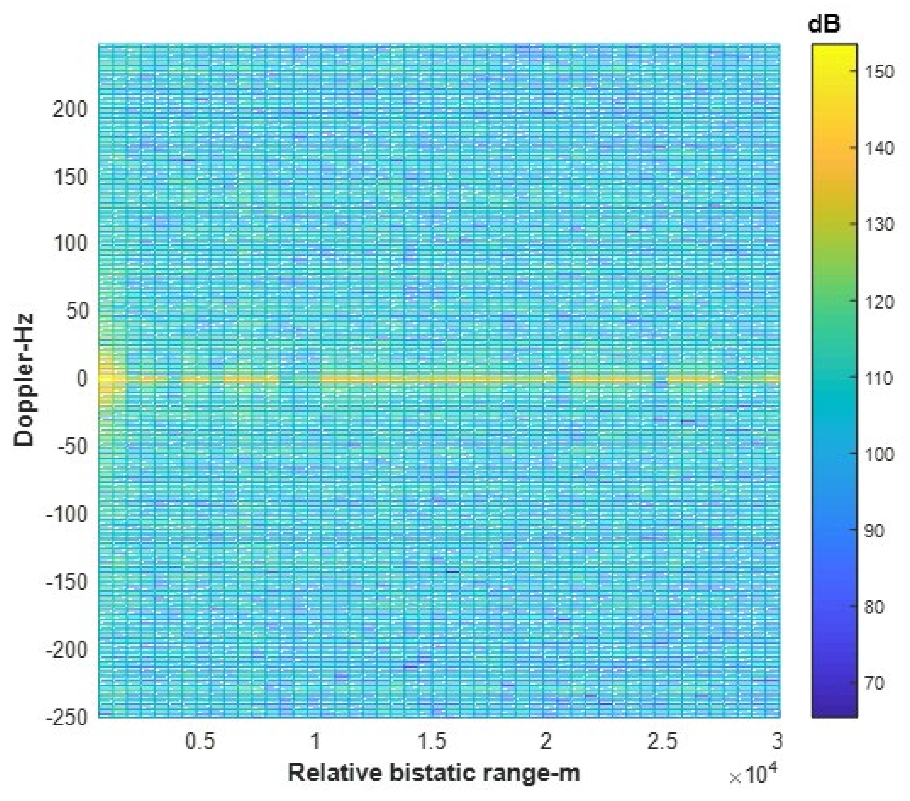
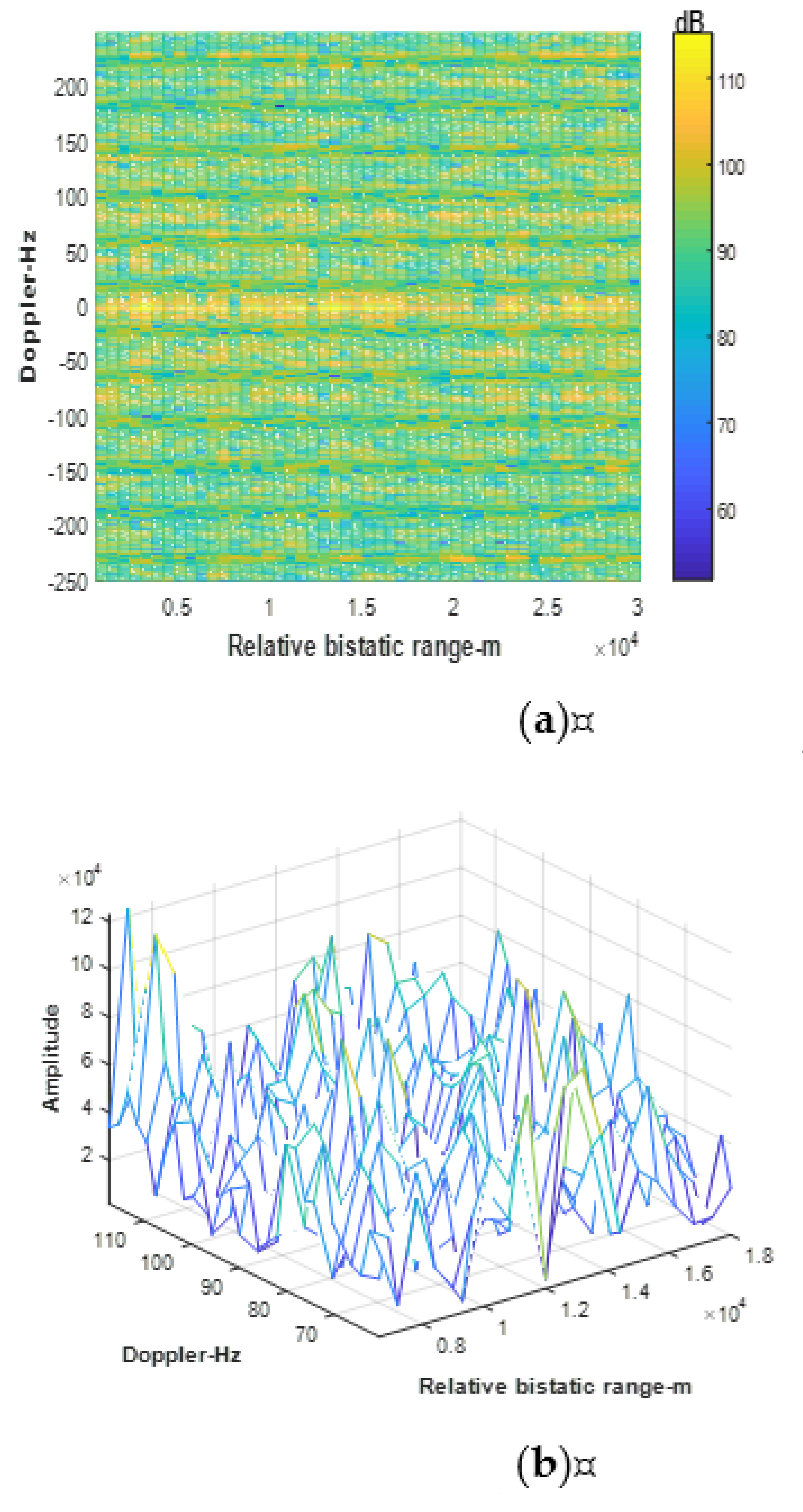
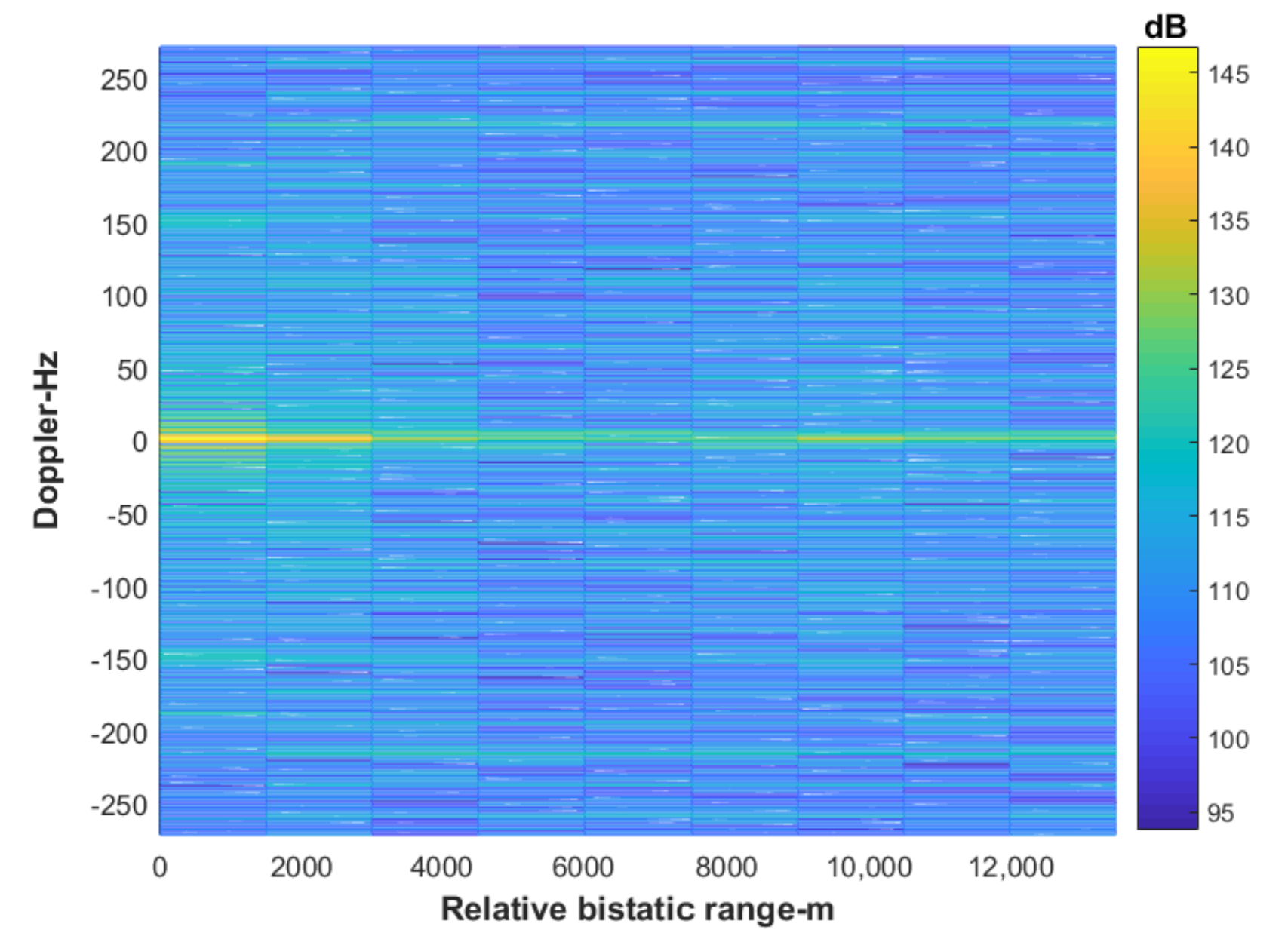
Firstly, the RDCC between the signal received by the echo antenna and the reference signal of BS-IoO is carried out. The result is shown in
Figure 3. It can be seen from
Figure 3 that due to the existence of strong DMI from BS-IoO, the target echo is covered under the sidelobes, so the target echo cannot be detected.
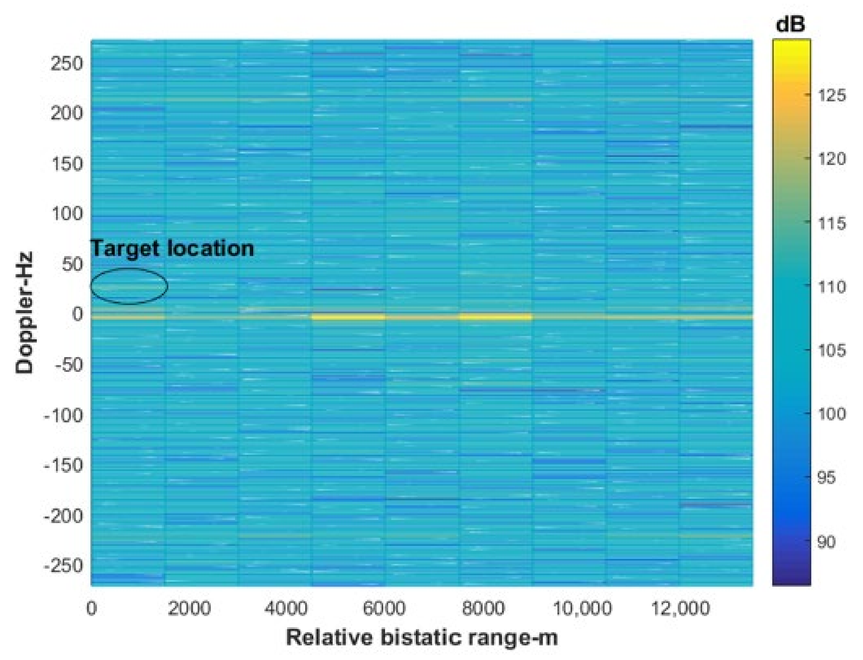
Following this, the ECA-B algorithm proposed in [
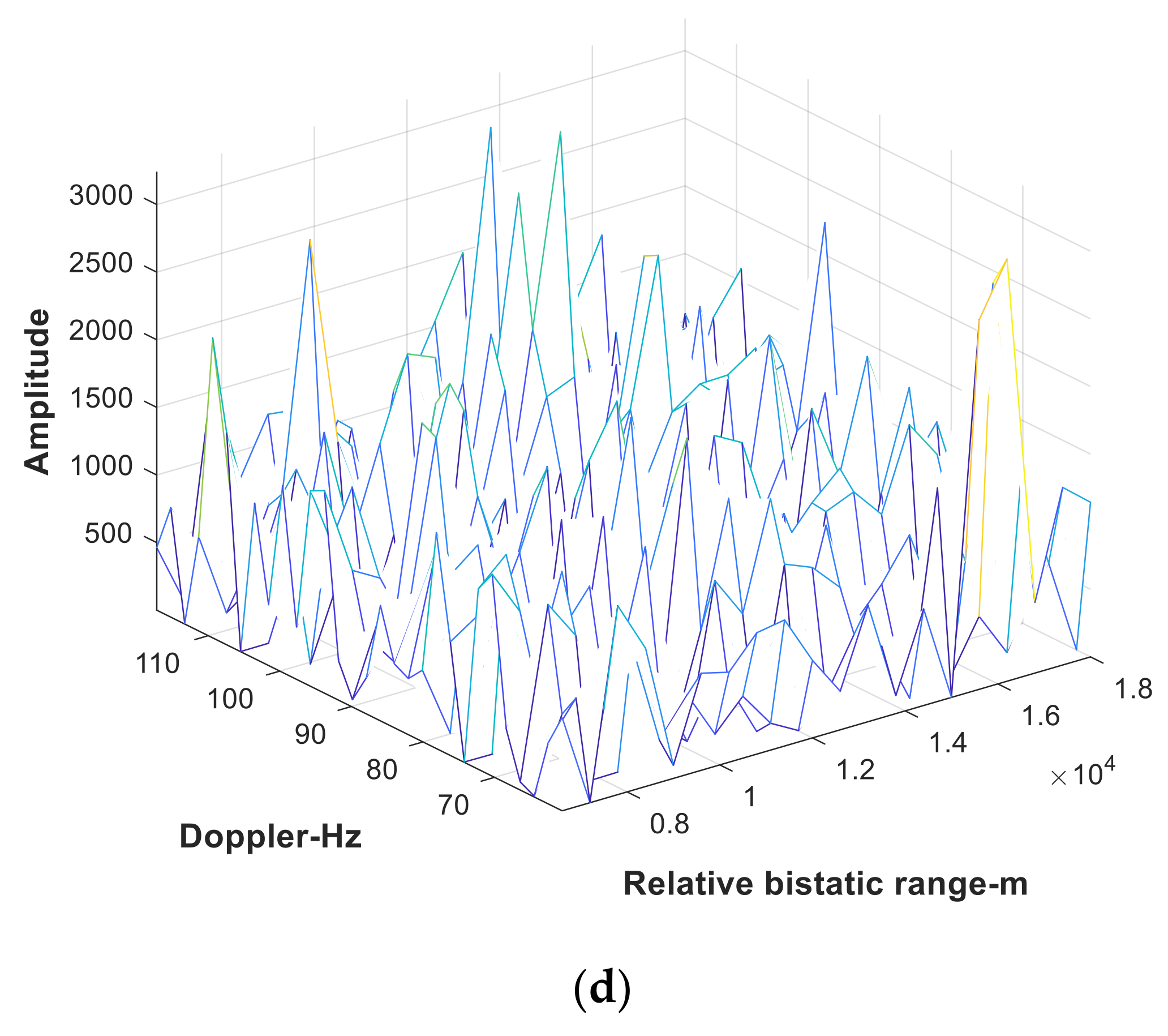
28] is used to cancel the DMI from BS-IoO. The range-Doppler result of the cancelled signal is shown in
Figure 4. It can be seen from
Figure 4 that the zero Doppler peak caused by the DMI of BS-IoO has been eliminated, but the target echo cannot be detected at this time, indicating that the residual interferences still seriously affect the detection of target echo. Therefore, the traditional method based on the principle of phase interference in [
17,
18,
19,
20,
21,
22,
23,
24] is difficult to be applied to the case of residual interferences.
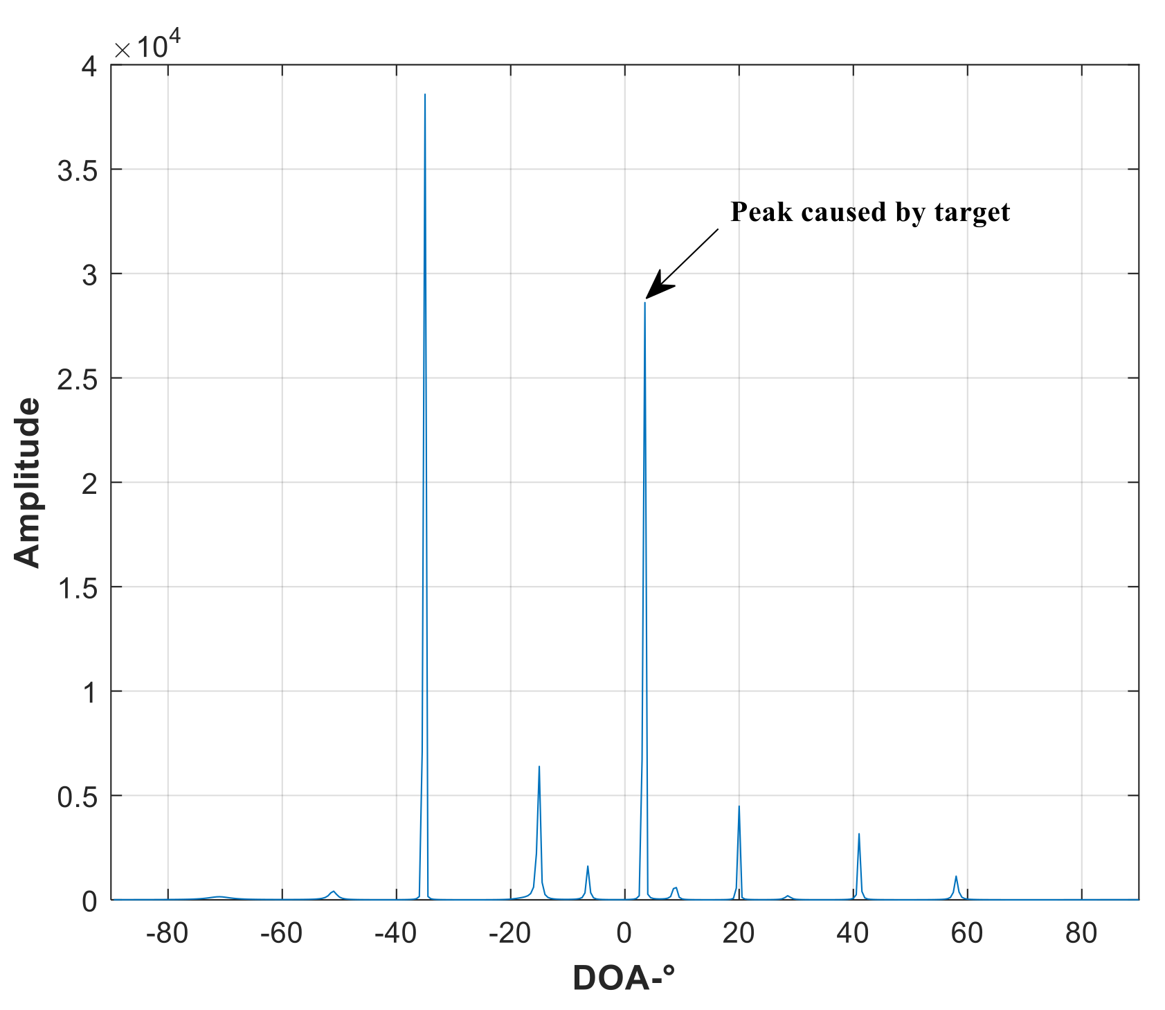
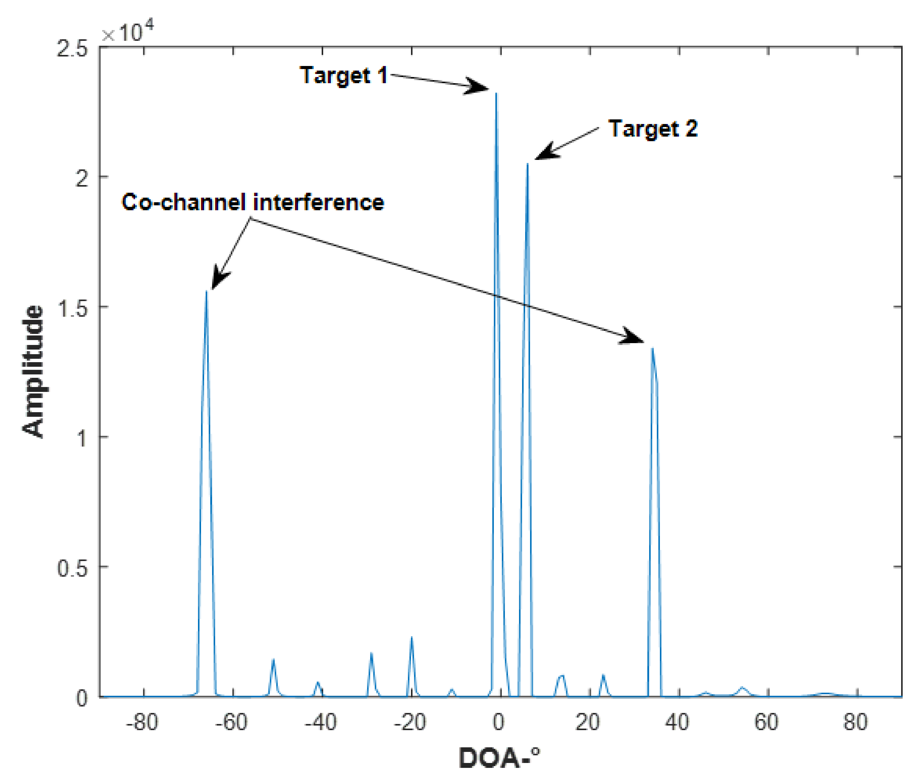
Next, in order to eliminate the influence of residual interference on target detection and DOA estimation, the azimuth sparse coarse reconstruction is performed on the signal of each range-Doppler unit. In the process of coarse reconstruction, the dimension of the observation matrix
is set to 16. The sparse reconstruction result corresponding to target range-Doppler unit is shown in
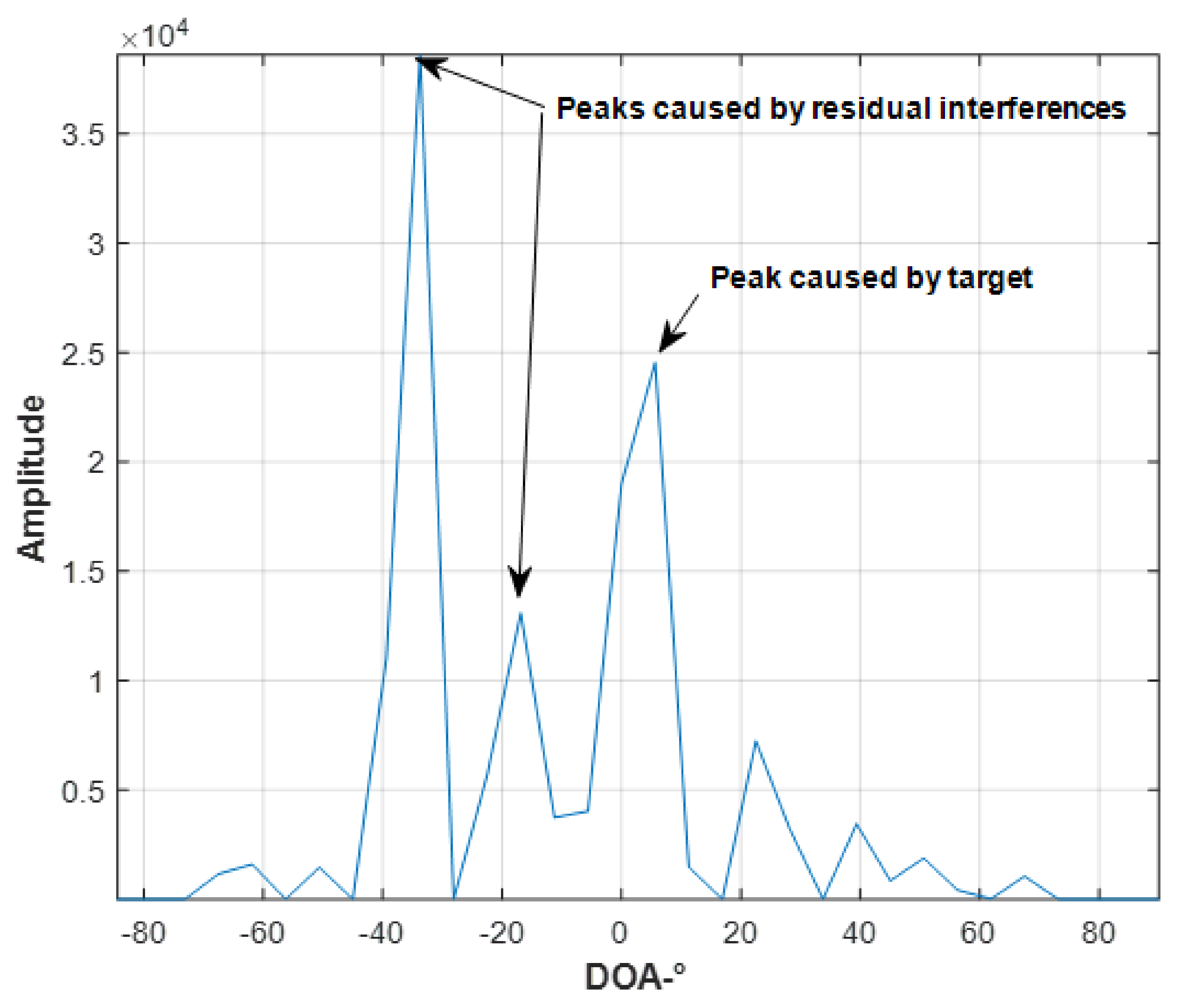
Figure 5. It can be seen from
Figure 5 that there is a peak caused by the target echo in the direction of 5.6° and peaks caused by strong interference sidelobes in the directions of −33.6° and −16.8°. This shows that the sparse reconstruction algorithm used in this paper can accurately reconstruct the signals in spatial domain. Therefore, when considering the residual interferences and target echo coming from different directions, they can be separated in spatial domain using sparse reconstruction.
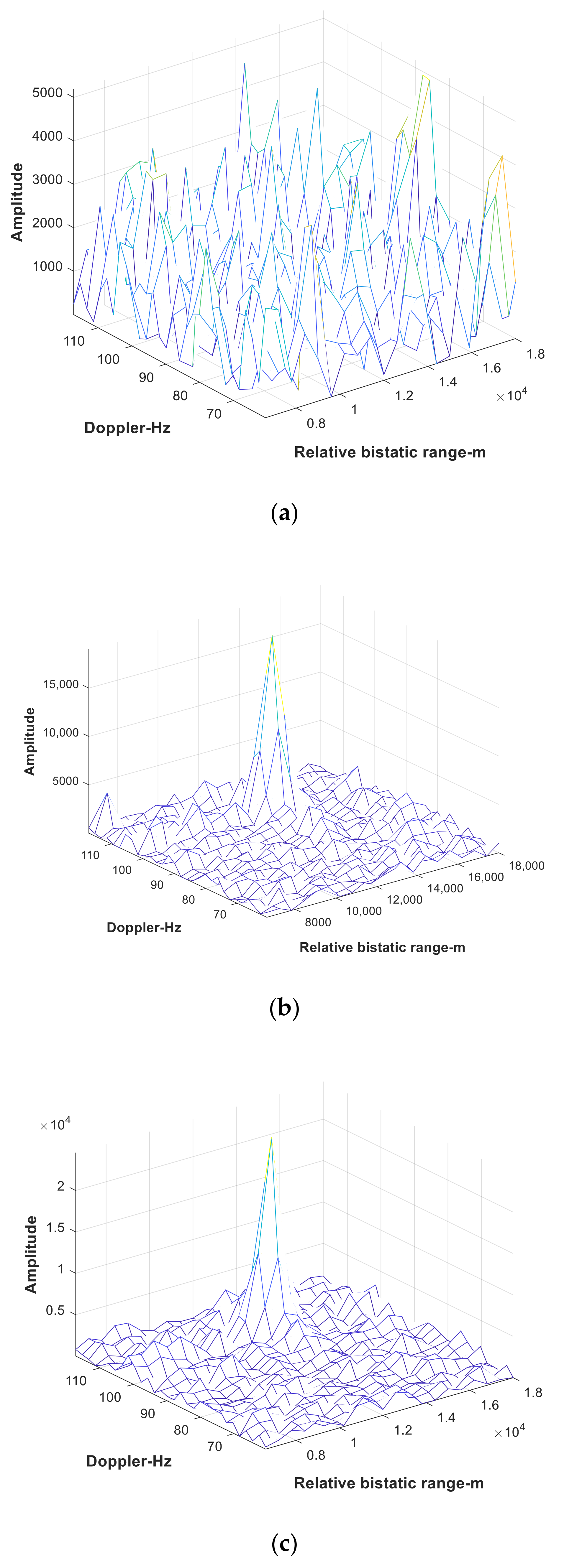
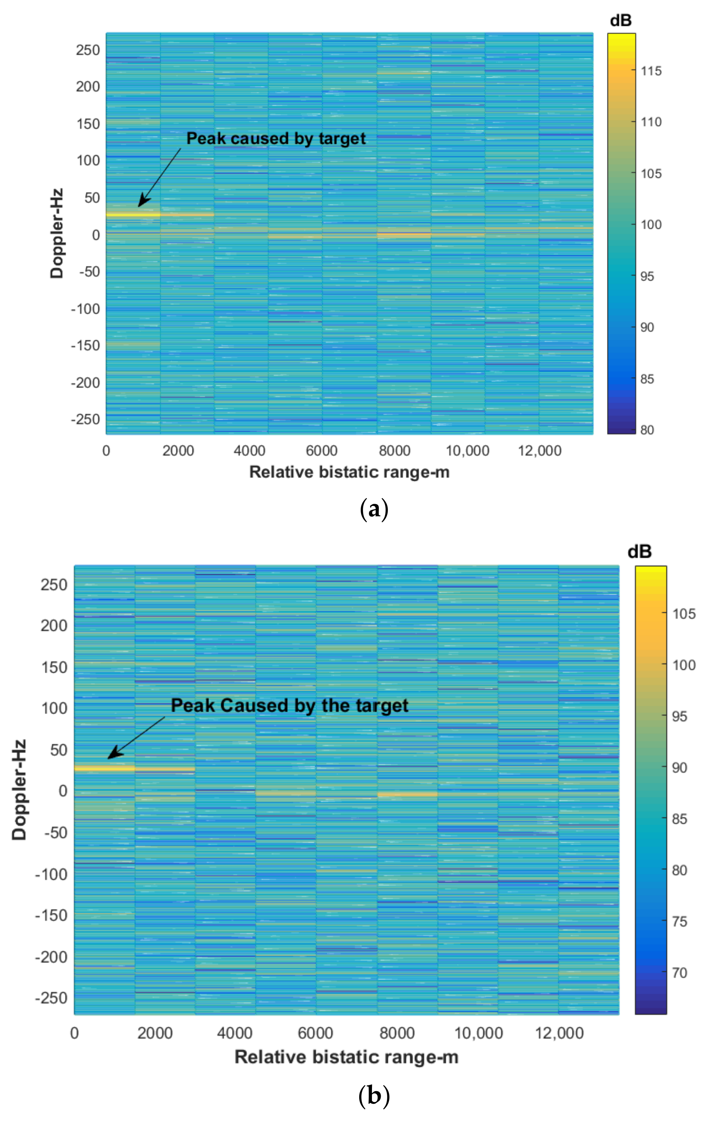
After sparse reconstruction of each range-Doppler unit, the range-Doppler two-dimensional matrix in different directions (from −90° to 90°) is constructed using the method described in Formulation (9).
Figure 6 shows only the results corresponding to the direction near the target. It can be seen from
Figure 6 that a peak caused by target echo can be detected in both 0° and 5.6° directions (as shown in
Figure 6b,c), while no peak is detected in the −5.6° and 11.2° directions (as shown in
Figure 6a,d). This indicates that there is a target in the azimuth region of 0° to 5.6°.
In order to improve the DOA estimation accuracy of the target, the azimuth sparse fine reconstruction is performed on the range-Doppler unit corresponding to the target. In the process of fine reconstruction, the dimension of the observation matrix
is set to 180. The result of fine reconstruction is shown in
Figure 7. It can be seen from
Figure 7 that there is an obvious peak at 3.5°. Combined with the prior information of target azimuth (in the azimuth region of 0° to 5.6°) obtained by coarse reconstruction, it can be estimated that the accurate DOA of the target is 3.5°, which is consistent with the simulation.
4.1. Performance Analysis of Target Detection
This section analyzes target detection performance. The simulation conditions are as mentioned above. It is still assumed that the signals received by the echo antenna include 15 DMI from BS-IoO, 10 co-channel interferences (including 4 strong interferences and 6 weak interferences) and 1 target echo signal. The DOA of the target is set to 0°. The DOA of three strong co-channel interferences are set to random values, but not within the range of the target mainlobe. Thus, when the number of antenna elements is set to 16, the target detection performance of the proposed method and ADBF used in [
35,
40] is compared and analyzed.
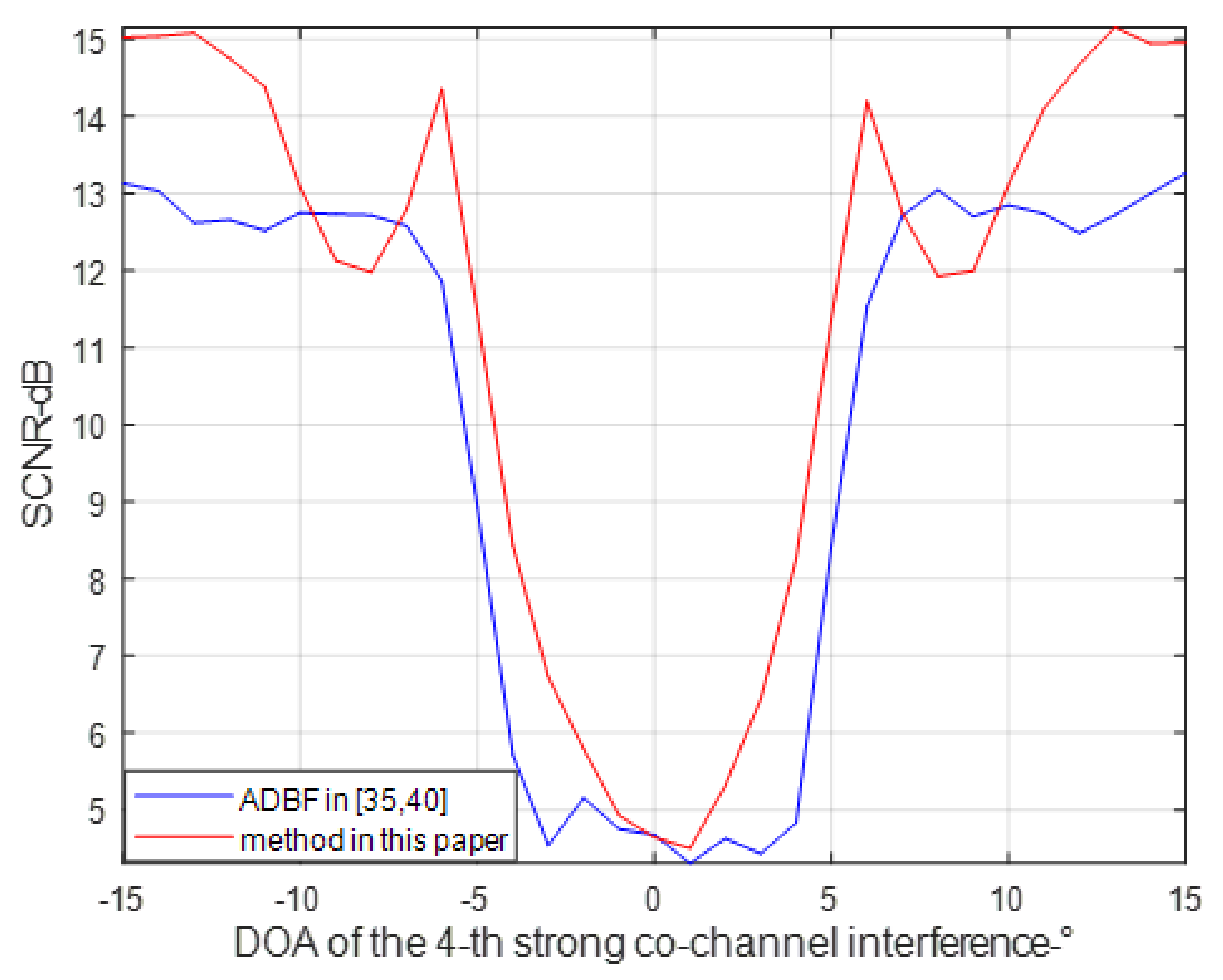
Figure 8 shows the results of 800 Monte Carlo experiments using these two methods, which describes the relationship between the SCNR of the target echo and DOA of the 4-th strong co-channel interference.
It can be seen from
Figure 8 that when all strong co-channel interferences are not located in the target mainlobe, the sparse reconstruction algorithm used in this paper and ADBF in [
35,
40] both can obtain good target detection performance (a detection SCNR of more than 12 dB can be acquired). When there is a strong co-channel interference signal within the target mainlobe, the performance of these two methods will decrease sharply due to the limitation of antenna freedom. However, it should be noted that, benefitting from the high resolution of sparse reconstruction algorithm, the proposed method has better anti-mainlobe interference ability than ADBF in [
35,
40]. For example, when the number of antenna array elements is 16, to obtain a target SCNR of 12 dB using ADBF, the angular spacing between the 4-th strong co-channel interference and the target echo should be 6.5°. However, using the sparse reconstruction algorithm proposed in this paper, the target SCNR of 12 dB can be obtained only when the angular spacing is only 5.5°. This means that compared with the traditional ADBF method, the method in this paper can get better anti-main lobe interference effects.
4.2. Performance Analysis of Single Target DOA Estimation
This section analyzes the performance of DOA estimation when there is only a single target in a range-Doppler unit. It is assumed that all strong co-channel interferences are located outside the target mainlobe, and the DOA of target is set to random. Other simulation conditions are the same as above.
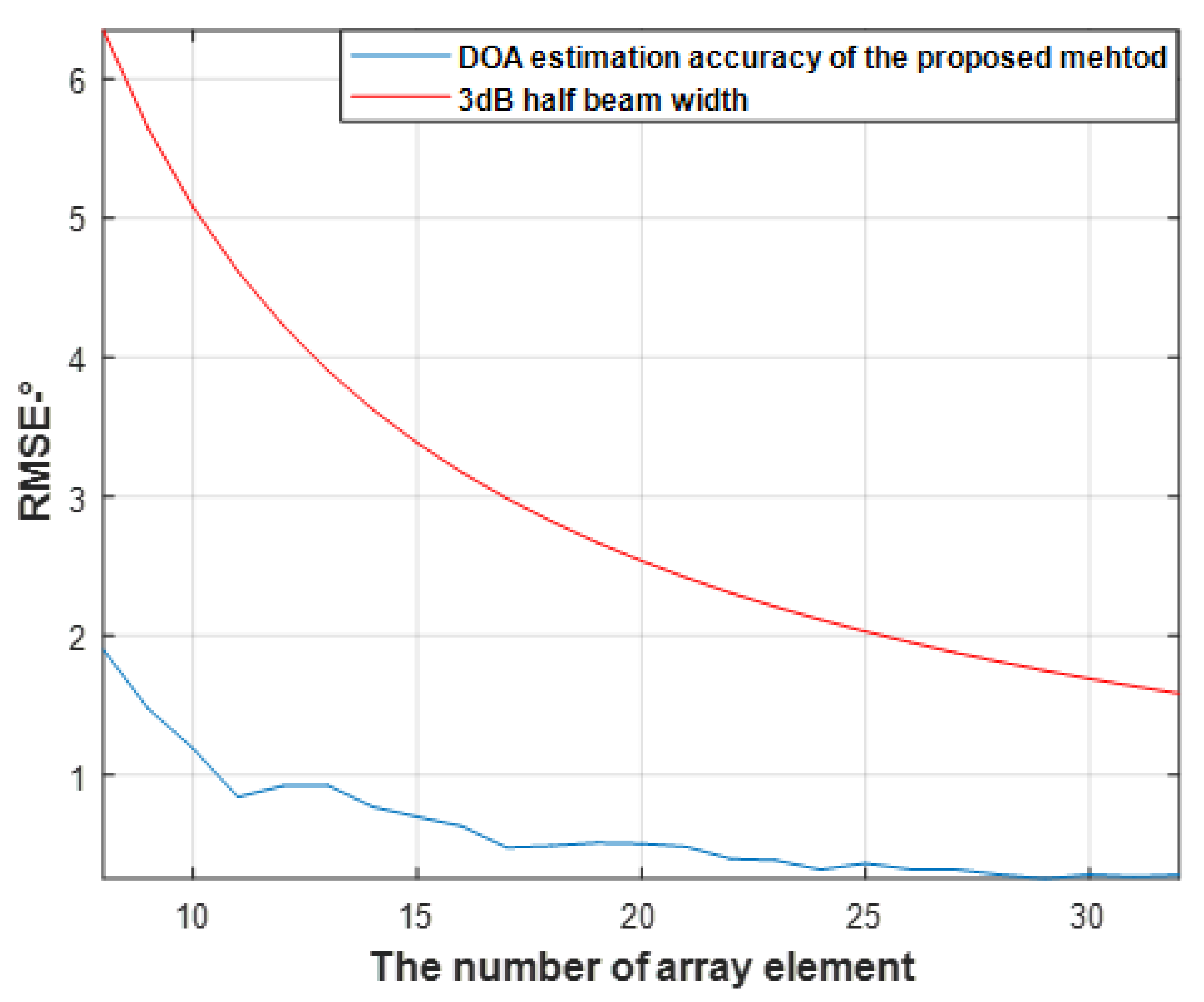
Figure 9 shows the results of comparing the performance of the proposed method with 3 dB half beam width through 800 Monte Carlo experiments when the number of antenna elements is different. As can be seen from
Figure 9, the DOA estimation accuracy obtained by the sparse estimation reconstruction algorithm is significantly better than the 3 dB half beam width of the antenna. For example, when the number of antenna elements is 16, the 3 dB half beam width of the array antenna is 3.17°, while the DOA estimation accuracy by the proposed method is 0.7°. Considering that in ADBF [
35,
36,
40] where all spatial degrees of freedom are used to suppress interferences, there are no airspace resources for accurate DOA estimation and the antenna beam pattern will also be distorted, resulting in the inability to use sum difference and amplitude comparison angle measurement. Moreover, the DOA estimation performance of ADBF is correspondent to the 3 dB half beam width of the antenna. Therefore, the DOA estimation accuracy of the proposed method will also be significantly better than that of traditional ADBF.
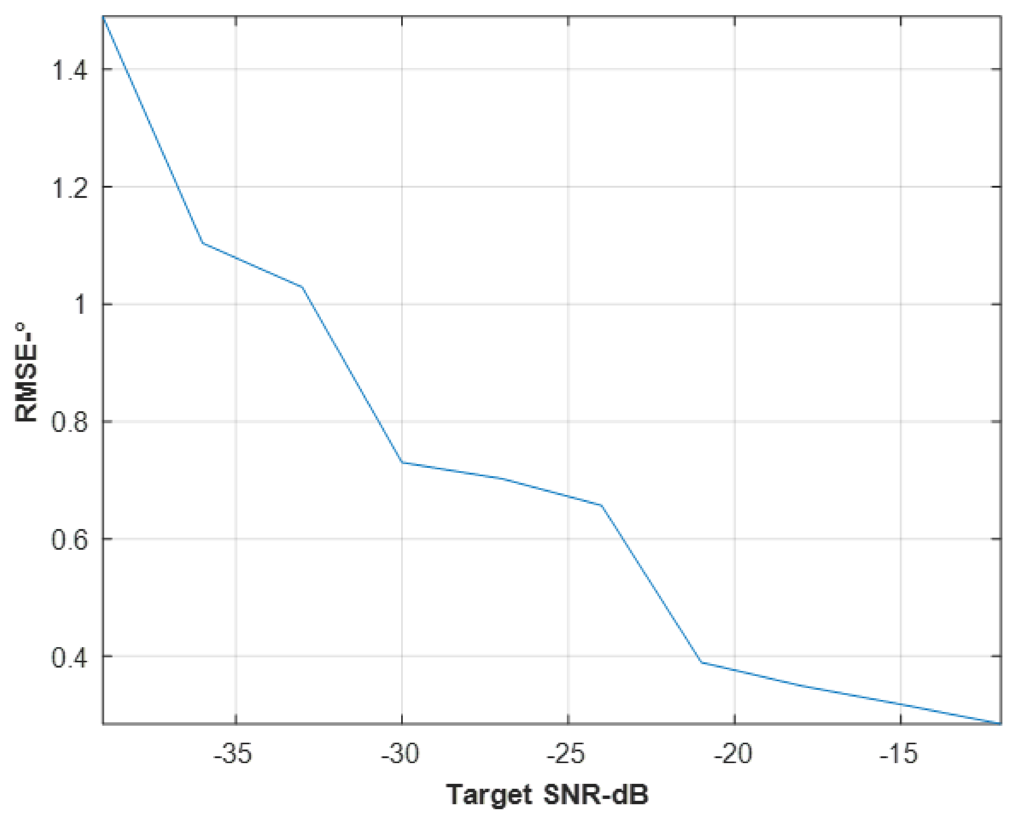
Thus, the relationship between the DOA estimation accuracy of the proposed method and target SNR is analyzed.
Figure 10 shows the target DOA estimation accuracy obtained using 800 Monte Carlo experiments when the target SNR ranges from −40 dB to −12 dB (in this simulation, it is assumed that the number of antenna elements is 16). It can be seen from
Figure 10 that when the target SNR is higher, the DOA estimation will be higher. For example, the −12 dB SNR of the target echo correspond to the 0.29° DOA estimation accuracy, while the −39 dB SNR of the target echo correspond to the 1.49° DOA estimation accuracy (it is still much better than the 3.17° DOA estimation accuracy of ADBF, the performance of which is related to the 3 dB half beam width of the antenna when all spatial degrees of freedom are used to suppress residual interferences [
35,
36]).
4.3. Performance Analysis of Multi-Target High-Resolution DOA Estimation
Due to the super-resolution characteristics of sparse reconstruction algorithm [
37,
38], the proposed method can not only realize DOA estimation when there is only one target in a range-Doppler unit, but it can also realize high-resolution target DOA estimation when there are multiple targets in a range-Doppler unit. Using the simulation conditions as above and assuming two targets’ echoes within a range-Doppler unit (the DOA of these two targets are set as 0° and 5°, respectively), the sparse reconstruction results corresponding to the target range-Doppler unit is shown in the
Figure 11. It can be seen from
Figure 11 that when the DOA interval (5°) of the two targets is less than the 3 dB beam width (6.34°) of the antenna, the sparse reconstruction algorithm used in this paper can achieve effective target separation and accurate DOA estimation.
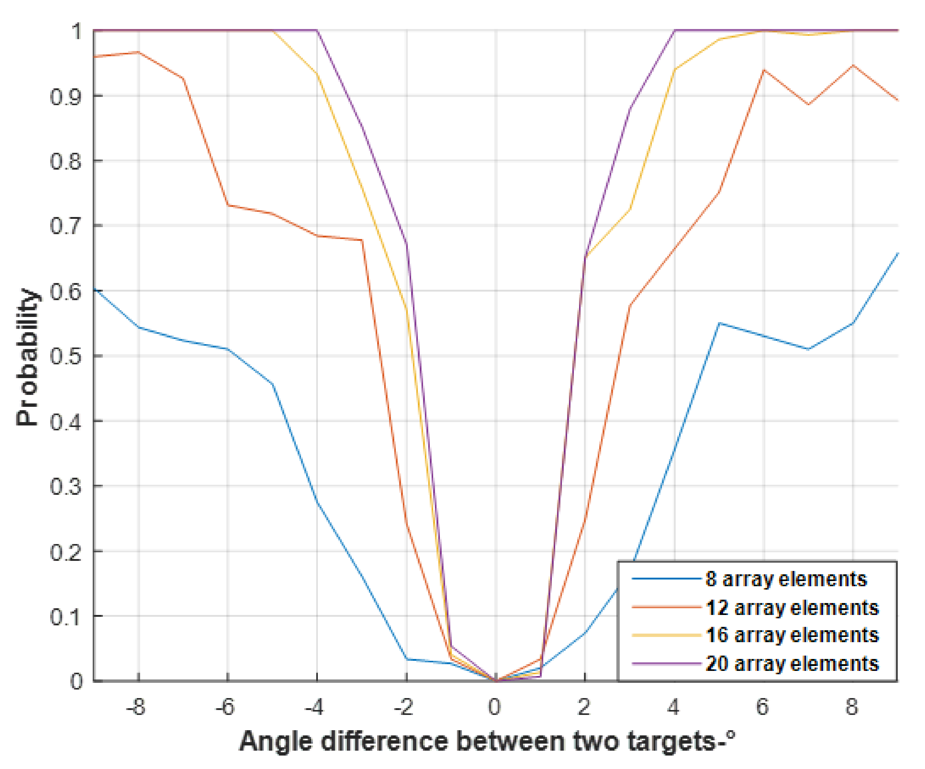
Next, the variation of high-resolution DOA estimation probability with the number of array elements and target angular spacing is simulated. It should be noted that in this paper, it is assumed that correct high-resolution target detection and DOA estimation can be achieved when two peaks in the target range-Doppler unit can be detected, and the difference between the estimated target DOA and the actual target DOA does not exceed 3 dB half beam width.
Figure 12 shows the results obtained by using 800 Monte Carlo experiments. It can be seen from
Figure 12 that the larger the number of antenna elements, the stronger the super-resolution DOA estimation ability. For example, when the number of antenna elements is 8 (3 dB beam width is 12.7°), in order to achieve a high-resolution DOA estimation probability of more than 60%, the angular spacing between the two targets should be greater than 9°. When the number of antenna elements is 20 (3 dB beam width is 5°), the high-resolution DOA estimation probability of more than 85% can be achieved only when the angular spacing between two targets is 3°.
5. Field Experiment Results
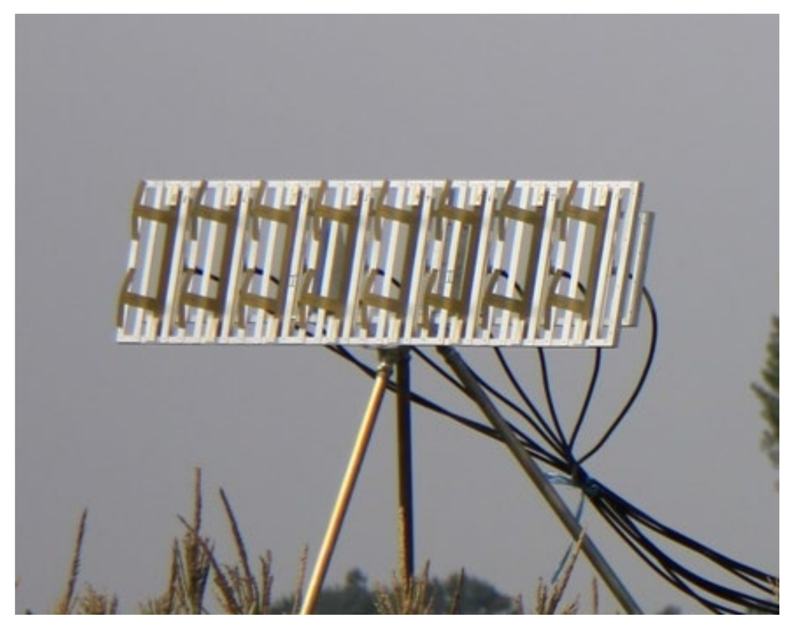
To prove the validity of the proposed method, we developed a PBR system. The uniform linear array of eight array elements was used as the receiving antenna to receive the moving target echo and DMI from both BS-IoO and BS-CF/AF. The array element spacing is 0.16 m, and the photograph of the antenna is shown in
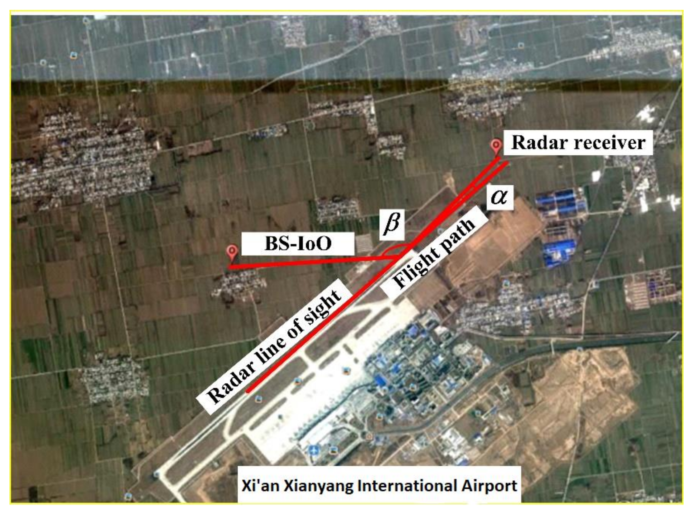
Figure 13. A field experiment was conducted in Xian, China, where the GSM signal was used as the IoO with a carrier frequency of 957 MHz, and the landing or civil aircraft take-off was set as the target of interest. The normal direction of the antenna was aligned to the direction of the airport runway, that is, the DOA of the target was set to about 0°. The sketch of the radar setup is shown in
Figure 14. Where
and
are set as the bistatic angle and the angle between radar line of sight and target flight path. From
Figure 14, we can see that when the aircraft is taking off, the DOA of the target is gradually getting closer to the normal direction of the radar.
The signals received by each array element are transformed into digital baseband signals after analog-to-digital conversion, digital down conversion, filtering, extraction and other operations. Moreover, the digital baseband echo signals with a sampling rate of 200 kHz are processed offline on a personal computer. The processing flow is shown in
Figure 15. As can be seen from
Figure 15, after channel equalization processing, the digital baseband echo signal is divided into echo channel and reference channel for processing, respectively. Following this, the reference signal of BS-IoO is obtained by the DBF in the reference channel. In the echo channel, the time-domain clutter cancellation is performed on the received signal of each array element to eliminate the DMI from BS-IoO, and then RDCC is performed to improve the target SCNR. Finally, sparse reconstruction algorithm is used for target detection and DOA estimation.
Figure 16 shows the result of RDCC of the original echo signal received (for all results of RDCC, the adopted coherent integration time is about 0.5 s in field experiment results. Because the signals received by the antenna include interferences both from BS-IoO and BS-CF/AF, and the energy of these interferences are much stronger than that of the target echo, the weak target echo is masked under the sidelobes of these strong interferences and cannot be detected.
Thus, the ECA-B clutter cancellation algorithm in [
28] and non-adaptive beamformer are performed on the received signal in turn, and the result of RDCC in the 0° direction is shown in
Figure 17. It should be pointed out that the weight vector of the non-adaptive beamformer is the steering vector of the antenna. It can accumulate target echo energy in spatial dimension but cannot suppress interferences adaptively in spatial dimension. It can be seen from
Figure 17 that the spikes in the zero Doppler unit have been eliminated, indicating that the interferences from BS-IoO have been effectively suppressed. However, due to the residual co-channel interferences, it is still impossible to detect the target echo.
In order to suppress residual co-channel interferences, the data after the clutter cancellation are processed using ADBF in [
35,
40] and sparse reconstruction algorithm, respectively. The corresponding results of which, in the 0° direction, are shown in
Figure 16. As can be seen from
Figure 18, both these methods can effectively suppress the residual co-channel interferences and detect the target. However, the target DOA estimation accuracy of ADBF is related to the 3 dB beamwidth of the antenna. When the number of antenna elements is small, the DOA estimation accuracy is very poor. For example, the target DOA estimation accuracy of ADBF is about 6.3° (see
Figure 9) when 8-element array antenna is used. Moreover, the sparse reconstruction algorithm can not only effectively suppress residual co-channel interference, but also realize accurate DOA estimation. From the simulation results of
Figure 9, it can acquire target DOA estimation accuracy of about 2°.
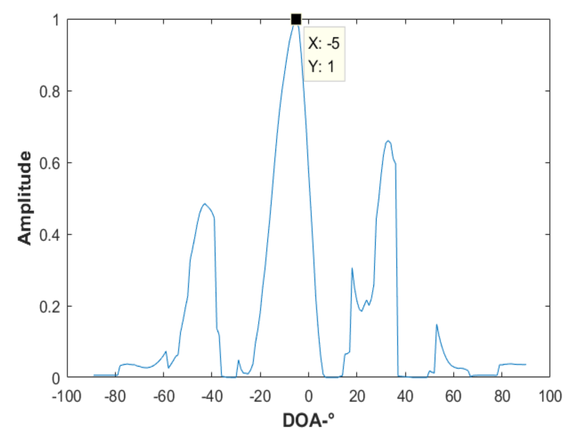
Figure 19 shows the result of sparse fine reconstruction of the target range-Doppler unit. It can be seen that it has an obvious peak at −5°. Combined with the prior information of coarse reconstruction in
Figure 18, it can be determined that the accurate DOA of the target is −5°. Spikes in other directions are the sidelobes formed by the residual co-channel interferences.
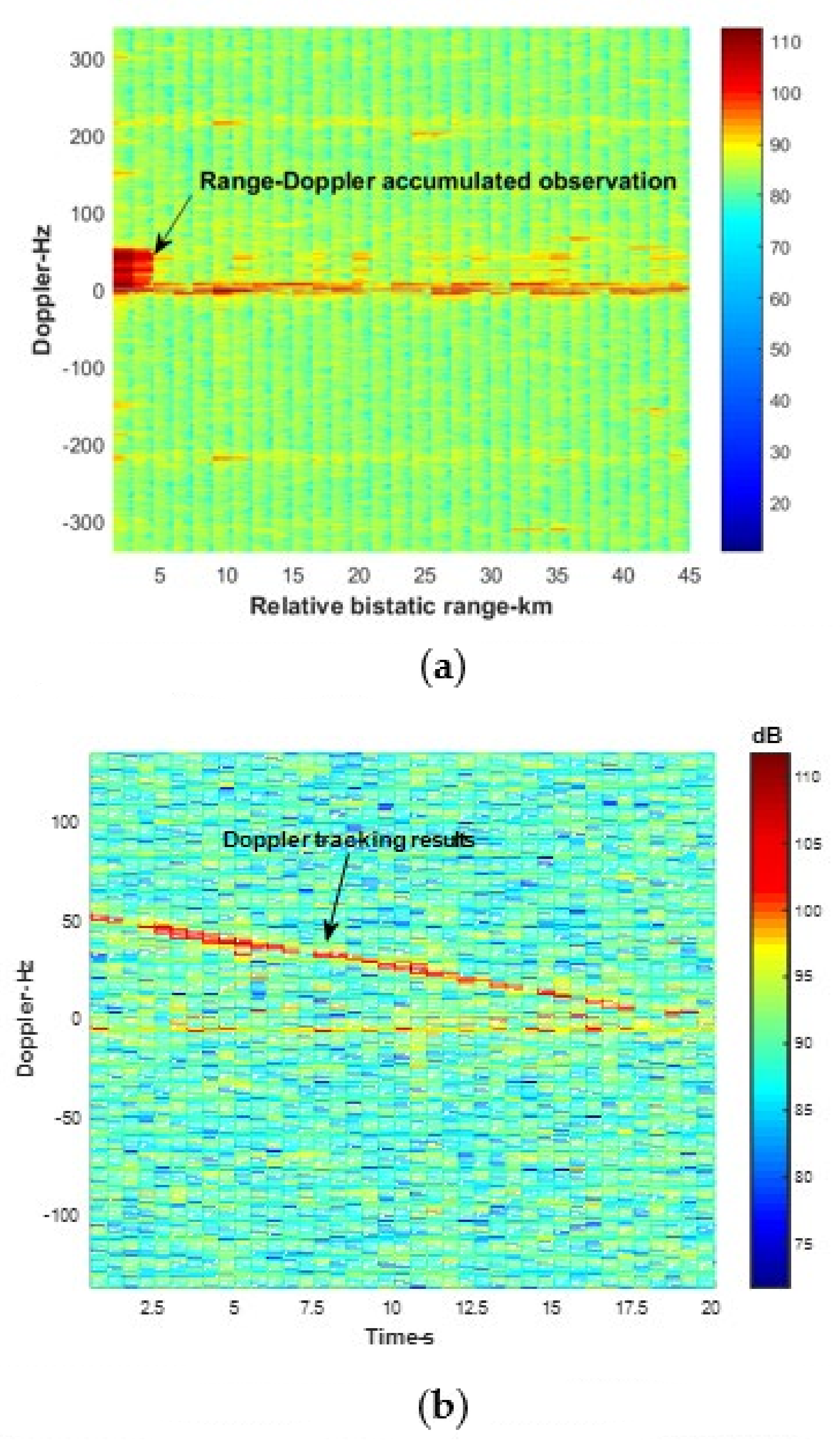
Figure 20 shows the target trajectory tracking results obtained after multi-frame processing using the sparse reconstruction algorithm.
Figure 20a shows the range-Doppler cumulative observation results of a landing aircraft. It should be noted that since the bandwidth of the GSM is about 80 kHz, corresponding to the distance resolution of about 1.8 km, the target is located in the same distance unit during the observation time.
Figure 20b shows the target Doppler trajectory tracking results. It can be seen that the stability detection of the landing aircraft can be realized by using the method proposed in this paper.
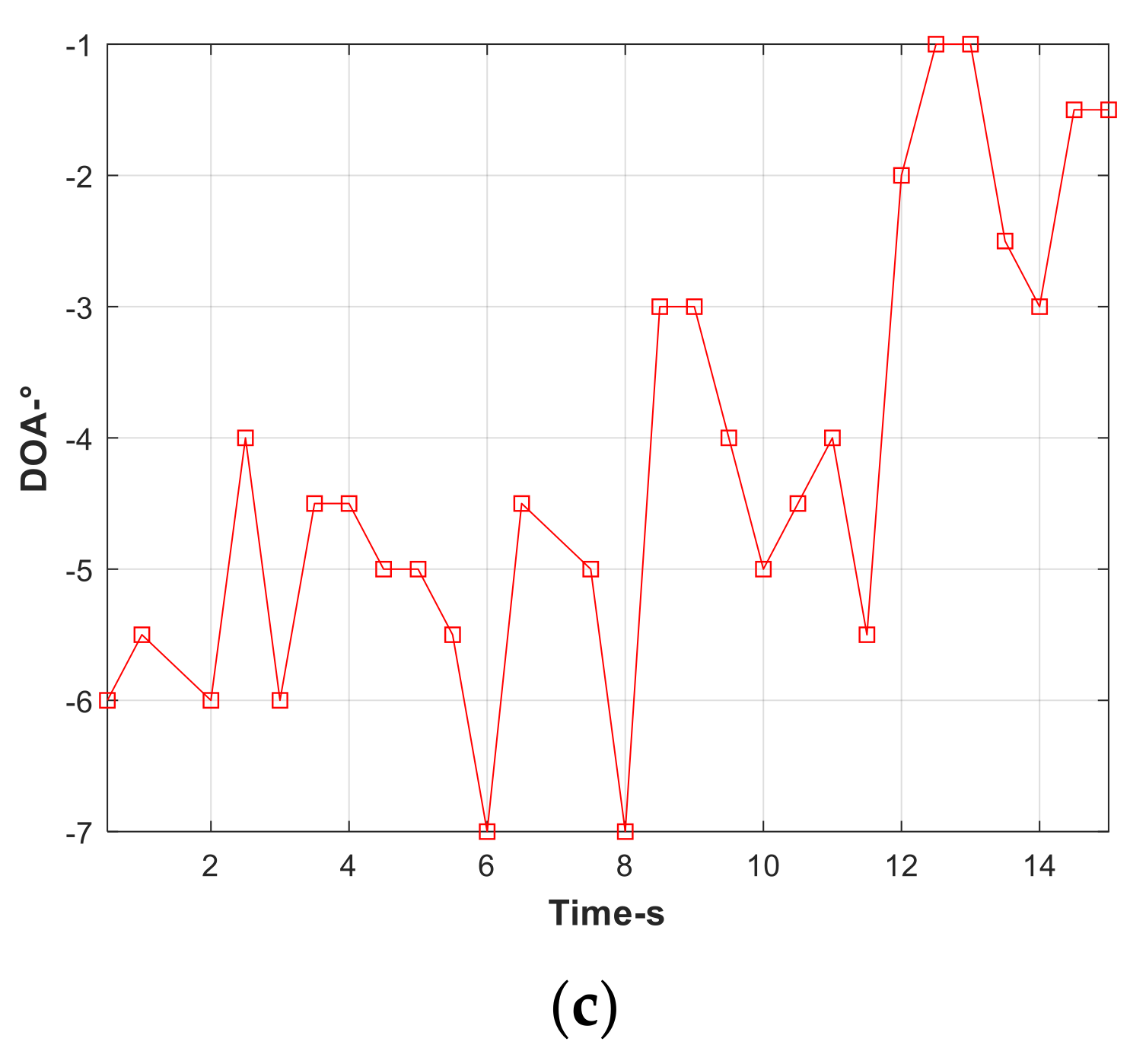
Figure 20c shows the target DOA trajectory tracking results. It can be seen that during the observation time, the DOA of the target changes from −6° to −1°, which is consistent with the actual target detection scene shown in
Figure 14.


