Technical Note

Longitudinal Evolution of Storm-Enhanced Densities: A Case Study

1
Key Laboratory of Earth and Planetary Physics, Institute of Geology and Geophysics, Chinese Academy of Sciences, Beijing 100029, China
2
Innovation Academy for Earth Science, Chinese Academy of Sciences, Beijing 100029, China
3
College of Earth and Planetary Sciences, University of Chinese Academy of Sciences, Beijing 100049, China
4
Heilongjiang Mohe Observatory of Geophysics, Institute of Geology and Geophysics, Chinese Academy of Sciences, Beijing 100029, China
5
Beijing Observatory of Space Environment, Institute of Geology and Geophysics, Chinese Academy of Sciences, Beijing 100029, China
*
Author to whom correspondence should be addressed.
Remote Sens. 2022, 14(24), 6340; https://doi.org/10.3390/rs14246340
Submission received: 24 October 2022 / Revised: 28 November 2022 / Accepted: 9 December 2022 / Published: 14 December 2022

Abstract

:
Due to the limitations on observational data, most storm-enhanced density (SED) studies have focused on the North American sector. The complete picture of the longitudinal evolution of SEDs is still not clear. In this study, we investigated the dynamic evolution of SEDs from the European sector to the North American sector during a geomagnetic storm that occurred on the 15 July 2012, the main phase of which lasted nearly 30 h, maintaining the stable interplanetary magnetic field (IMF) and solar wind input conditions. Multiple data sets were analyzed, including convection data from the Super Dual Auroral Radar Network (SuperDARN), total electron contents (TECs) from the Madrigal database, plasma data from the Millstone Hill incoherent scatter radar (MHISR), solar wind and geomagnetic indices from OMNIWeb, and regional auroral electrojet indices from SuperMAG. The observations showed that the positions of SEDs shifted from local noon over the European sector towards dusk over the American sector and simultaneously moved to lower latitudes. The peak values of SED TECs were found to be greater in the European sector and to decrease with universal time. A double SED phenomenon appeared in the North American sector, which is the first of its kind to be reported. Further analysis showed that the temporal and spatial changes in the SEDs were associated with the eastward auroral electrojet.

1. Introduction

During a geomagnetic storm, the ionosphere at middle and high latitudes shows significant density enhancements in certain spatially narrow areas which we call storm-enhanced densities (SEDs). SEDs always appear in local time sectors from afternoon to pre-sunset. Their spatial locations are mainly near the equatorward boundary of the ionospheric mid-latitude trough [1]. On a two-dimensional global total electron content (TEC) map, an SED structure is illustrated as latitudinal narrow bands of increased TECs [2]. Foster et al. [3,4,5,6] found that these SED counterparts in the plasmasphere are caused by erosion of the outer plasmasphere, which results from the driving force of the sub-auroral electric field.
SED structures have been observed and investigated over the United States for more than a decade. Most studies have reported SEDs over North America using observations or simulations [4,7,8,9,10,11]. Several observations have been reported over Europe [12,13,14] and over Japan [15]. One reason for this phenomenon is the limited global coverage of GPS receivers at middle and high latitudes, especially in Russia. Another reason is the longitudinal dependence of the SED occurrence rate due to the displacements between the geographic and the geomagnetic coordinates. High-latitude convections, controlled by the geomagnetic field, transport solar photoionization plasmas at middle latitudes poleward and westward and lift plasma upward [16,17,18,19]. This dynamic process produces SED plumes. However, in the Northern Hemisphere, the high-latitude convection pattern is asymmetric with respect to the geographical axis. This means that the strength of this dynamic process is different in different longitudinal sectors.
Liu et al. [16] observed an SED event during a minor geomagnetic storm. Their results showed that both the peak electron density of the F2 layer (NmF2) and the peak height of the F2 layer (hmF2) increased, and the TEC value of the SED also increased due to the electron density increases at high altitudes. Foster et al. [4,5] and Zou et al. [19] studied the formation of SEDs using measurements from the Millstone Hill incoherent scatter radar (ISR) and Poker Flat ISR. They found a large sunward horizontal plasma drift velocity of more than 1000 m/s and a vertical plasma drift velocity of approximately 100 m/s in the SED plumes. Yizengaw et al. [20] analyzed all images from the Imager for Magnetopause-to-Aurora Global Exploration (IMAGE) Extreme Ultraviolet Imager (EUV) databases and corresponding TECs from the Madrigal database of the Massachusetts Institute of Technology (MIT) provided by a ground network of global positioning system (GPS) receivers [21]. Their results suggested that during the time a plasmaspheric plume can be seen, one can find an SED structure occurring in the North American sector with almost one hundred percent probability. However, the probability of the occurrence of an SED over the European sector is less than fifty percent, and that for an occurrence over the Asian sector is the smallest, with a value of twenty percent. The authors believed that there might be two reasons for the longitudinal difference. One reason is that the position of these plumes may exceed the limit of the GPS receiver field of view. The other reason is that weak SED structures may not be detected by the sparse GPS receivers in the Asian sector.
Coster et al. [2] presented some examples of SED developments in the Eastern Russian, American, and European sectors. They found that the motion of the SED base was obviously westward and that the drift velocity was less than the corotation velocity. The authors found that the SED remained stable in local time near noon and that its magnetic latitude ranged from 61° to 63° in the European sector. The observations also showed that in the American sector the time of occurrence of the SED base always moved from local noon to local dusk and that its position shifted to lower latitudes at almost the same longitudinal region. They also found that the TEC value of the SED base was larger in the North American region under magnetically disturbed conditions with a geomagnetic index (Kp) = 6.
As mentioned above, most SED studies have focused on the American sector due to the adequate GPS-TEC data and ISR data for this region [7,22,23,24,25]. Coster et al. [2] selected several magnetic storms to study the variations in SED structures without considering the effect of the stability of the IMF and cross-longitudinal evolution in a single storm. However, the longitudinal evolution process of SED structures is still not clear. It is well known that the characteristics of SEDs are substantially influenced by the interplanetary magnetic field (IMF) and the geomagnetic field [9,12,26,27,28]. The temporal variations in the interplanetary magnetic field are generally unstable. Consequently, it is difficult to tell whether the time evolution of an SED is caused by changes in the interplanetary magnetic field or a longitudinal sector effect. In this study, a magnetic storm that occurred on 15 July 2012, the main phase of which persisted steadily for 30 h, was used to investigate the characteristics of SEDs over the European and North American sectors.

2. Data and Methods

In this study, the data sets utilized included global maps of GPS-TEC data, OMNI solar wind parameters, geomagnetic indices, plasma data from the Millstone Hill incoherent scatter radar (MHISR), regional auroral electrojet indices from SuperMAG, and convection data retrieved from the Super Dual Auroral Radar Network (SuperDARN). OMNI is a multi-source platform for sharing near-Earth solar wind magnetic field and plasma data. Most of the data have a time-resolution of one hour and cover the period from November 1963 to the present. The processing algorithms used to obtain vertical GPS TEC measurements have been described in detail by Rideout and Coster [29], and the SuperMAG data processing technique has been described in detail by Gjerloev [30]. SuperDARN has been one of the most powerful tools for studying dynamical processes in the Earth’s magnetosphere, ionosphere, and neutral atmosphere for over 10 years [31]. SuperDARN comprises similar ground-based coherent-scatter radars that operate in the high-frequency (HF) band, the fields of view of which combine to cover extensive regions of the polar ionosphere in both the Northern and Southern Hemispheres [32].
For every five-minute interval, the GPS TEC data were averaged into bins with a resolution of 1° × 2° in geomagnetic latitude and longitude in the MLAT/MLT coordinate system. SED plumes were found by examination of adjacent TEC bins. Figure 1 shows a typical SED pattern on a TEC map of the Northern Hemisphere in the MLAT/MLT system, with magnetic noon at the top, indicated by the white arrow. The white line denotes the baseline of an SED plume, where the poleward propagating SED separates from the middle latitude with a high TEC value. The bold black curves indicate the contours, with a value of 13 TECu, which are the poleward and equatorward boundaries of the SED plume, where TECs are instantaneously enhanced. The maximum TEC bin (mTECb) is defined as the bin with a maximum TEC value in an SED area. The maximum TEC value (mTEC) is defined as the TEC value of the mTECb. Determining an SED plume is not always possible, primarily due to sparse GPS receiver coverage over land areas and oceans. If an SED plume can be identified manually for each averaged map, the averaged universe time (UT), mTEC, magnetic latitude (M-Lat) and magnetic local time (M-LT) of the mTECb, and the locations of the boundaries of the SED pattern can be determined.

3. Results

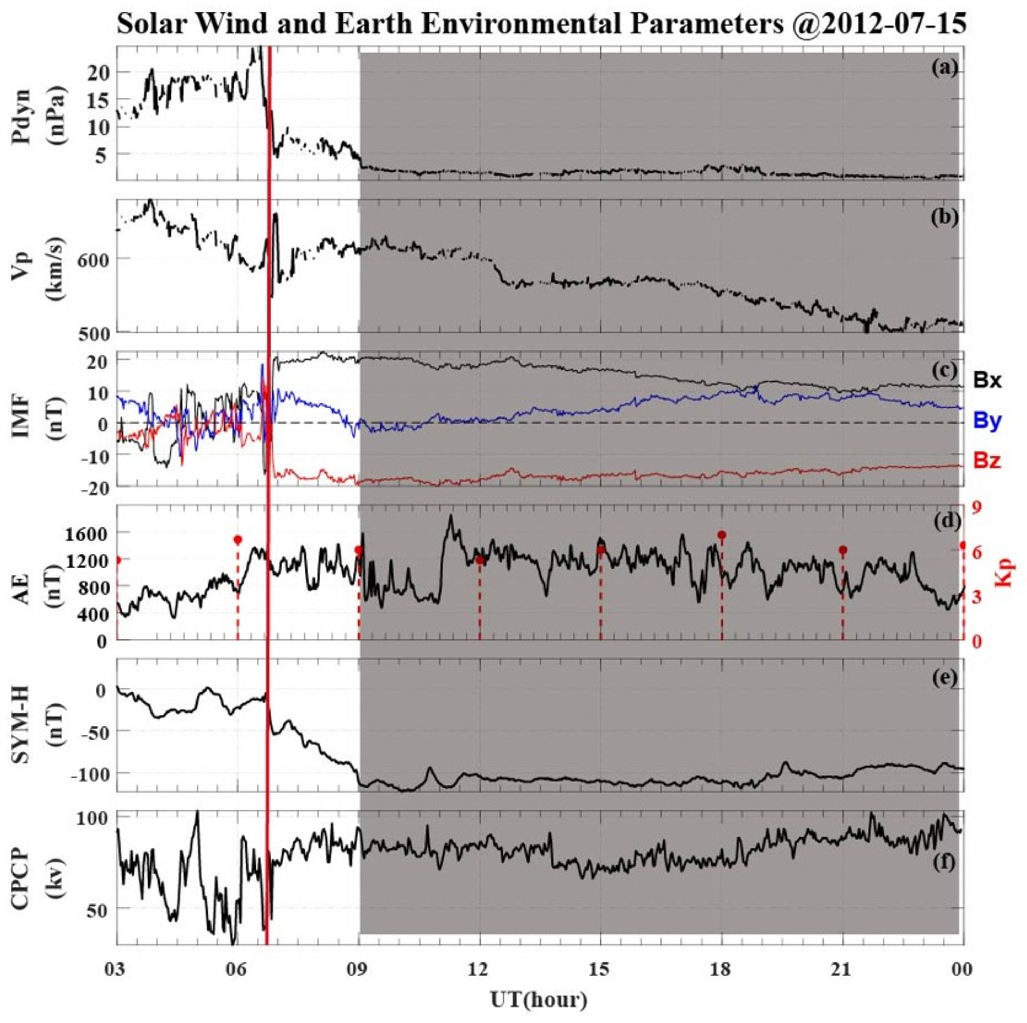
Figure 2 shows the variations in solar wind and IMF parameters (panels a, b, c), as well as SYM-H (panel e), AE and Kp indices (panel d), and the cross polar cap potential (CPCP) (panel f) during a coronal-mass-ejection-driven magnetic storm on 15 July 2012. At about 06:40 UT on 15 July 2012, indicated by the red vertical line in Figure 2, the solar wind dynamic pressure decreased rapidly and the IMF Bz turned southward suddenly, as shown in panels 2a and 2c. Panel 2d shows that the AE index increased and reached about 1400 nT and that the Kp index exceeded 6, which indicated that the geomagnetic field was significantly disturbed. The SYM-H index was continuously negative from this time and reached a minimum value of around −110 nT at 09:00 UT. The CPCP fluctuated before 06:40 UT and then reached about 80 kV for more than 20 h. The shaded area is the time period we are interested in here. From 09:00 UT to 24:00 UT on 15 July 2012, all solar wind parameters and indexes were quite stable. This protracted stable solar wind driving condition, which exceeded 16 h, makes this event significantly different from other magnetic storms. At the same time, it means that the energy from the solar wind entered the Earth’s magnetosphere and ionosphere stably and continuously. This event provides an excellent chance to study the longitudinal dependence of SEDs without the effect of IMF changes.
The left panels of Figure 3(a1–d1) show the evolution of the polar view of the GPS TECs in the Northern Hemisphere, with local noon at the top. We can obtain an SED pattern and calculate the SED’s boundaries according to the TECs’ spatial distribution. The boundaries of the SED pattern are recorded in the right panels (a2–d2). At 09:37 UT (panel a1), an SED pattern occurred over the European sector near local noon and expanded in magnetic latitude. The boundaries of the SED plume indicate that the magnetic latitude of the SED plume exceeded 62°, and the SED moved from noon to midnight, as shown in panel a2. Panels b1 and b2 (at 12:32 UT) show an SED pattern over the Northwest European sector towards the North Atlantic sector, where observations are absent. The magnetic latitude of this SED plume was similar to that shown in Figure 3(a1). However, the configuration of the SED rotated and moved to the afternoon with a velocity approximately equal to the rotational speed of the Earth. As time progressed, SED patterns at 20:32 UT and 21:32 UT appeared over the Northeast American sector and the continental United States and Canada sectors. In panels c2 and d2, the magnetic latitude of the SED can be seen to have moved to lower latitudes. The SED moved to a later magnetic local time and then faded away due to chemical recombination. In the American sector (panels c1 and d1), the SED expanded in magnetic latitude and longitude; the gradient of the poleward boundary of the SED was larger than that of the equatorward boundary. The configuration of the SED was east–west.
Examination of the longitudinal dependence of the TEC magnitude of the plume provided insight into the TEC available in the source region of the SED. Figure 4 plots the parameters for the maximum TEC value in an SED area versus universal time. As shown in Figure 4, the data gap observed between 13:00 UT and 19:00 UT was due to the poor coverage of the GPS receivers over the Atlantic Ocean. The black and red rectangular boxes denote the European and North American sectors. Panel a shows the magnitude of the mTEC. The largest mTEC value was seen in the European sector and reached about 21.6 TECu, and the maximum TEC values of the SEDs in each TEC map decreased with time. Panels b and c show the magnitude of magnetic latitude and magnetic local time of the mTECb, respectively. The blue and black thick lines indicate linear fits to the parameters of the mTECb. M-Lat decreased with time from a high to low magnetic latitude, and there was a slight difference in the rate of magnetic latitudinal change in the mSEDb between these two longitudinal sectors—1.6°/hour in the European sector and 1.44°/hour in the American sector. M-LT increased with time from local noon to afternoon, and the increase in the North American sector was faster than that in the European sector.

4. Discussion

As indicated in Figure 3, the SEDs in the European sector were near noon and expanded from noon to midnight in magnetic latitude, similar to SEDs in the Alaska sector [19]. These two sectors are roughly symmetric about the geomagnetic axis. The North American SEDs were seen in the afternoon, and their directions were east–west. Foster et al. [5] reported that the sub-auroral polarization stream (SAPS) electric field overlaid the TEC reservoir at the TEC base at ionospheric heights and was located equatorward of the aurora oval. The shape and location of the SAPS channel were controlled by high-latitude convection cells [33,34]. At the dusk side, the SAPS channels were distributed along the convection circle, showing a southeast–northwest shape. The plasma was then drawn along the SAPS channel, producing the SED plume. Yuan et al. [35] and Zhang et al. [13,14] declared that SEDs flowed to the cusp, formed the tongue of ionization (TOI), and then crossed the polar cap to the nightside ionosphere. These effects can make the configurations of SEDs consistent with the contours of high-latitude convection circles.
Due to the angle between the geomagnetic axis and the geographical axis, the locations of high-latitude convection cells are different in different longitudinal sectors. In the Northern Hemisphere, the high-latitude convection circle attains its lowest geographic latitude in the American sector and contracts until it reaches its maximum latitude in the Russian sector. As shown in Figure 4, in the Northern European sector, the daytime electron densities, which overlap with high-geographical-latitude regions controlled by high-latitude convection cells, reach the maximum of a day near local noon. This effect makes SEDs appear near local noon. In the North American sector, the high-latitude convection circle expands to lower geographic latitude regions, which restrains the formation of SEDs. However, later, the convection circle develops to a higher latitude and carries high-density plasma poleward, so the SED occurs in the afternoon sector.
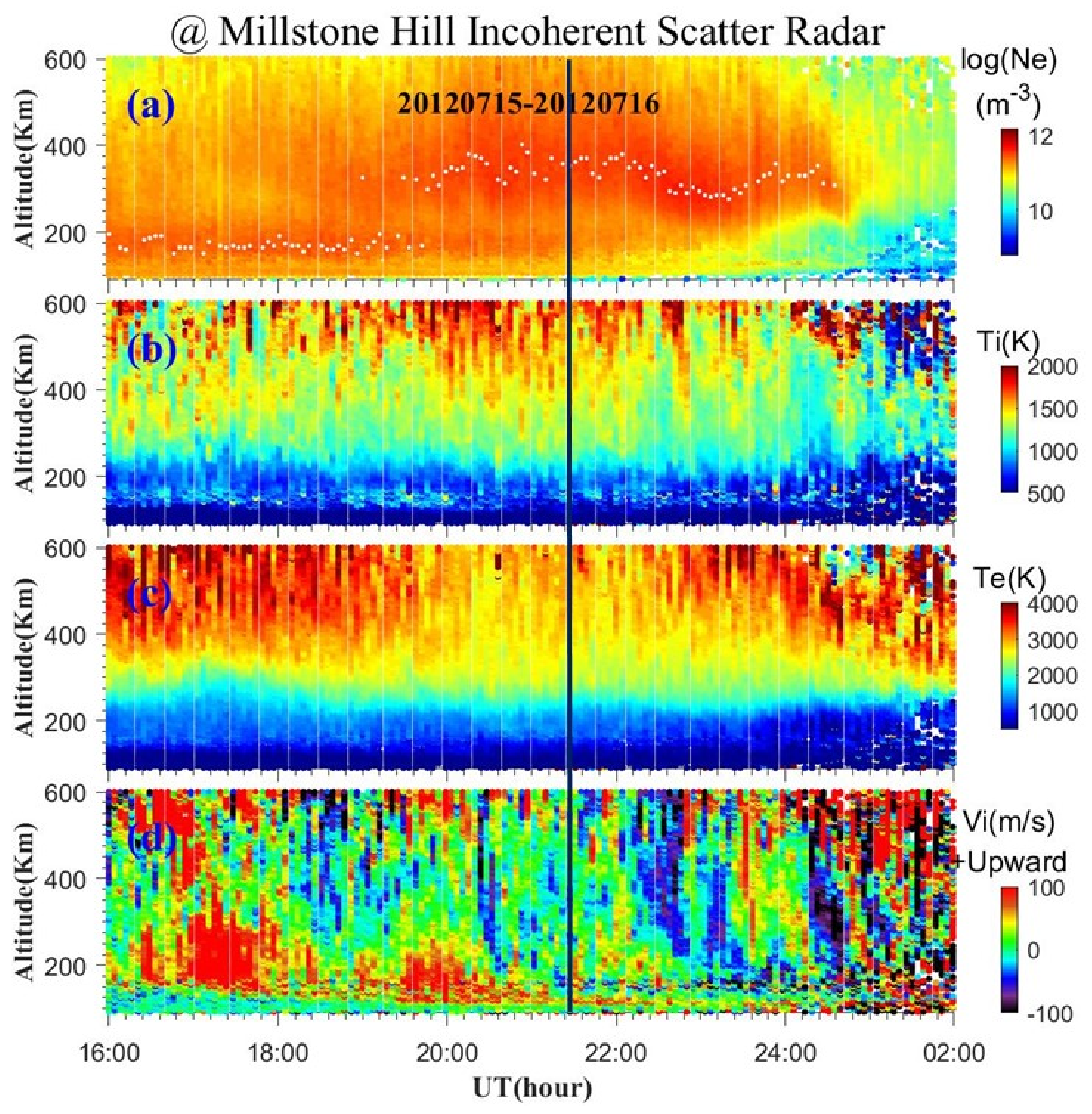
Coster et al. [2] revealed that there is a significant difference in the rate of latitudinal change in the SED plume base between these two longitudinal sectors—1°/hour in the European sector and 2.4°/hour in the American sector. Looking back at Figure 4b, we can see that the M-Lat variation in the American sector can actually be divided into two segments: one between 20:00 UT and 21:40 UT, and the other between 21:40 UT and 23:00 UT. The former has a better linear correlation. The linear fitting for the period 20:00 UT–21:40 UT is shown by the red line. The latitudinal rate of change in the mSEDb is 2.84°/hour. This means that the magnetic latitudinal rate agrees well with Coster’s result (2.4°/hour). As the Earth rotates under the convection pattern, the region of sunward convection extends to lower geographic latitudes as time progresses from 16 UT to 22 UT [24]. The convection pattern continuously encounters solar-produced F region plasma, which is picked up in a snowplow effect and carried westward and poleward. For constant activity conditions, the variation in the latitudes at which SEDs occur is very similar to that in the equatorward extent of the convection electric field [36]. In the period 21:40 UT–23:00 UT, the magnetic latitude of the mTECb remained approximately constant between 50° and 52°, and the extent of the convection pattern retreated poleward in geographic coordinates [30]. Considering that the M-LTs were greater than 17 in this period, the SEDs faded away due to the fact that the middle and low latitudinal ionospheres could not provide high-density plasma to form an SED by high-speed sunward flow. At about 21:40 UT, there were TEC enhancements, as shown in panel 4a. Figure 5 shows an SED observed by the Millstone Hill incoherent scatter radar (MHISR), which was under the SED structure from 19:30 UT to 24:00 UT on 15 July 2012. Panels 5a–5d illustrate the electron density, ion and electron temperatures, and ion vertical velocity, with positive values shown to be upward and negative values to be downward. The white dots in panel 5a represent hmF2s, and the black vertical line marks the universal time of 21:40. For the period from 21:30 UT to 22:10 UT, panels 5a and 5d show that the hmF2 increased slightly and that the ion vertical velocities were positive under about 400 km, respectively. This means that the enhancement of TEC was due to the transportation of low-altitude ionospheric plasma to the high-altitude ionosphere.
The peak values of SEDs became smaller in the North American sector due to the weakening of photochemical ionization in the afternoon, as represented in Figure 4a and Figure 3(a1–d1). We calculated the solar zenith angle (SZA) and found that the SZA was 68° in the European sector and 36° in the North American sector. Converted to solar radiation flux, this was about twice as large in the European sector as in the North American sector.
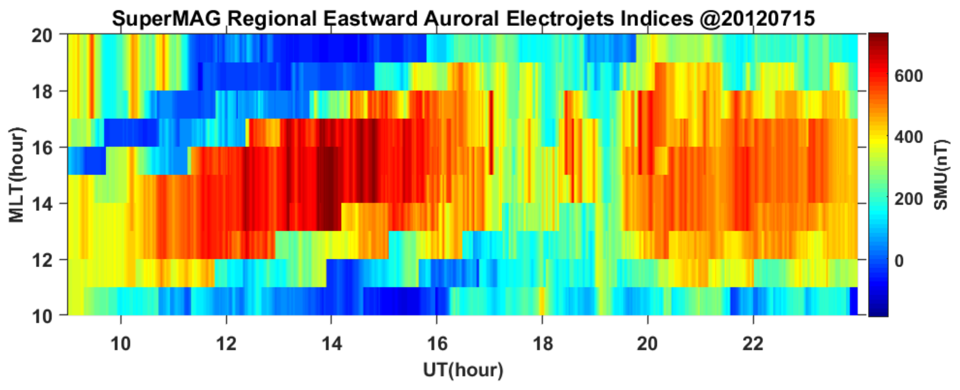
Our results show that the SEDs moved from local noon to afternoon and from high latitudes to lower latitudes. Eastward electric fields raised the plasma to higher altitudes where the recombination rates were lower [37]. Lifting of the F-region plasma in this region has been reported by Yin et al. [38] and modeled in simulation studies [23,39,40]. We used the regional eastward auroral electrojet indices from SuperMAG to study the relationship between the eastward electric field and the SEDs’ motions. As shown in Figure 6, regional eastward auroral electrojet indices over the European sector expanded to later magnetic local time from 12 MLT to 15 MLT. However, in the North American sector, these decreased and covered more MLTs. The characteristics of regional eastward auroral electrojet indices were consistent with the SEDs’ motions from noon to afternoon.
We found that the SuperMAG regional eastward auroral electrojet indices in the North American sector were smaller than those in the European sector. Considering the decrease in mTECs shown in Figure 4a, the decrease in regional eastward auroral electrojet indices affected the decrease in mTECs with time due to the horizontal sunward velocity leading to the vertical transport of plasma.
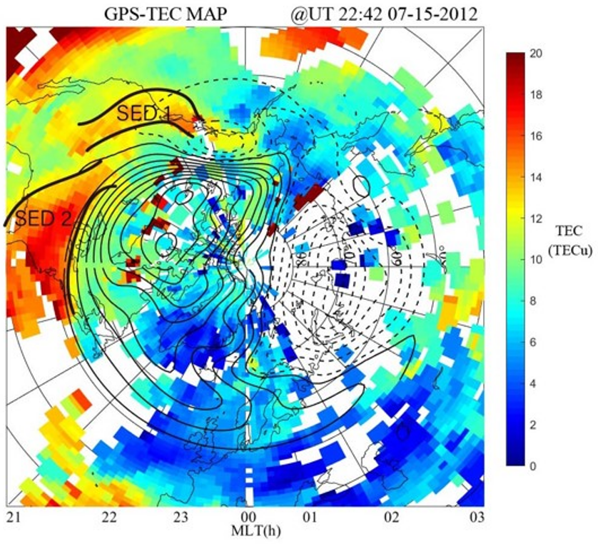
In the late main phase, an interesting phenomenon occurred. As illustrated in Figure 7, a double SED pattern occurred in the Northern Hemisphere at 22:42 UT on 15 July 2012. One of the double SEDs, named SED-2, was located on the East Coast of the American continent. The other one, named SED-1, was located on the West Coast. The observations showed that the double SED structures lasted for about 1 h. However, since there were no TEC data for the longitudinal sectors of Japan and Russia, we are not sure whether this structure lasted longer. Without more TEC data or in situ satellite data, we do not know enough about this double SED structure’s spatial and temporal variations, nor do we know its formation process. We hope to obtain more data in the future to help us understand this double SED structure and how it forms. Here, we present two possible explanations for the formation of the double SEDs. One explanation is that SED-1 was cleaved from SED-2 due to a shear action of convective velocity gradients. Another explanation is that these two SEDs were formed at the same time, and they may not have developed by the same mechanism.

5. Conclusions

In this study, we selected a magnetic storm event that occurred on 15 July 2012 with a protracted main phase to study the longitudinal evolution of SED structures. As shown in Figure 1, the solar wind and interplanetary magnetic field conditions remained stable for a long time during this magnetic storm. This indicates that the energy entering the Earth’s ionospheric space remained relatively stable, which provided us with an excellent opportunity to study the longitudinal evolution of SEDs for the first time. We analyzed GPS TEC data to report the longitudinal changes in SED structures from the European sector to the North American sector during the storm. Our results reveal that, from the European to North American sectors, the occurrence time of SED structures gradually moved from noon to afternoon and that their positions moved to lower latitudes. The largest value for the maximum TEC in the SEDs was recorded in the European sector, and the velocities of SED motions differed greatly between the two longitudinal sectors. By comparing the motions of the SEDs with the variation in the eastward auroral electrojet indices, we found that the two were well correlated. Therefore, we think that the east electric field may play an important role in the longitudinal dependence of SED structures. In addition, based on the GPS TEC observations, we have reported a double SED pattern for the first time in the North American sector.

Author Contributions

Conceptualization, B.L. and H.L.; Data curation, B.L. and H.L.; Formal analysis, B.L. and H.L.; Methodology, B.L. and H.L.; Validation, L.L., Y.C. and W.L.; Writing—original draft, B.L. and H.L.; Writing—review and editing, B.L., H.L. and L.L. All authors have read and agreed to the published version of the manuscript.

Funding

This research was supported by the B-type Strategic Priority Program of the Chinese Academy of Sciences (XDB41000000), the National Natural Science Foundation of China (42030202, 41822403), and the Youth Innovation Promotion Association CAS (Y201915).

Data Availability Statement

The regional auroral electrojet index data from the SuperMAG are provided on the website (https://supermag.jhuapl.edu/mag/, last accessed 12 October 2022). The solar wind parameters are available in the NASA/GSFC OMNI database (https://spdf.gsfc.nasa.gov/pub/data/omni/high_res_omni, last accessed 12 October 2022). The geomagnetic index can be downloaded online; the Massachusetts Institute of Technology (MIT) Haystack Observatory supplies the community GPS TEC data in the Madrigal database (http://www.openmadrigal.org, last accessed 12 October 2022). The Super-DARN data can be accessed from the website (http://vt.superdarn.org, last accessed 12 October 2022).

Acknowledgments

B. Li would like to thank Qinghe Zhang of Shandong University for the opportunity to study the polar ionosphere and study the Super-DARN radar data processing and Tong Dang and Jiacheng Li. for their discussions about and suggestions for this article.

Conflicts of Interest

The authors declare no conflict of interest.

References

  1. Foster, J. Storm time plasma transport at middle and high latitudes. J. Geophys. Res. Earth Surf. 1993, 98, 1675–1689. [Google Scholar] [CrossRef]
  2. Coster, A.J.; Colerico, M.J.; Foster, J.C.; Rideout, W.; Rich, F. Longitude sector comparisons of storm enhanced density. Geophys. Res. Lett. 2007, 34, L18105. [Google Scholar] [CrossRef]
  3. Foster, J.; Vo, H. Average characteristics and activity dependence of the subauroral polarization stream. J. Geophys. Res. Atmos. 2002, 107, 1475. [Google Scholar] [CrossRef] [Green Version]
  4. Foster, J.C.; Erickson, P.J.; Coster, A.J.; Goldstein, J.; Rich, F.J. Ionospheric signatures of plasmaspheric tails. Geophys. Res. Lett. 2002, 29, 1623. [Google Scholar] [CrossRef] [Green Version]
  5. Foster, J.C.; Coster, A.J.; Erickson, P.J.; Rich, F.J.; Sandel, B.R. Stormtime observations of the flux of plasmaspheric ions to the dayside cusp/magnetopause. Geophys. Res. Lett. 2004, 31, L08809. [Google Scholar] [CrossRef] [Green Version]
  6. Foster, J.; Rideout, W.; Sandel, B.; Forrester, W.; Rich, F. On the relationship of SAPS to storm-enhanced density. J. Atmos. Solar Terr. Phys. 2007, 69, 303–313. [Google Scholar] [CrossRef]
  7. Fagundes, P.R.; Cardoso, F.A.; Fejer, B.G.; Venkatesh, K.; Ribeiro, B.A.G.; Pillat, V.G. Positive and negative GPS-TEC ionospheric storm effects during the extreme space weather event of March 2015 over the Brazilian sector. J. Geophys. Res. Space Phys. 2016, 121, 5613–5625. [Google Scholar] [CrossRef] [Green Version]
  8. Goldstein, J.; Sandel, B.R.; Hairston, M.R.; Reiff, P.H. Control of plasmaspheric dynamics by both convection and sub-auroral polarization stream. Geophys. Res. Lett. 2003, 30, 2243. [Google Scholar] [CrossRef] [Green Version]
  9. Sojka, J.J.; David, M.; Schunk, R.W.; Heelis, R.A. A modeling study of the longitudinal dependence of storm time midlatitude dayside total electron content enhancements. J. Geophys. Res. Earth Surf. 2012, 117, A02315. [Google Scholar] [CrossRef]
  10. Vo, H.B.; Foster, J.C. A quantitative study of ionospheric density gradients at midlatitudes. J. Geophys. Res. Earth Surf. 2001, 106, 21555–21563. [Google Scholar] [CrossRef]
  11. Weimer, D.R. A flexible, IMF dependent model of high-latitude electric potentials having ‘‘ace weather’’ applications. Geophys. Res. Lett. 1996, 23, 2549. [Google Scholar] [CrossRef]
  12. Yizengaw, E.; Moldwin, M.B.; Galvan, D.A. Ionospheric signatures of a plasmaspheric plume over Europe. Geophys. Res. Lett. 2006, 33, L17103. [Google Scholar] [CrossRef]
  13. Zhang, Q.; Zhang, B.; Liu, R.; Dunlop, M.W.; Lockwood, M.; Moen, J.; Yang, H.; Hu, H.; Hu, Z.; Liu, S.; et al. On the importance of interplanetary magnetic field |By| on polar cap patch formation. J. Geophys. Res. 2011, 116, A05308. [Google Scholar] [CrossRef]
  14. Zhang, Q.; Zhang, B.; Moen, J.; Lockwood, M.; McCrea, I.W.; Yang, H.; Hu, H.; Liu, R.; Zhang, S.; Lester, M. Polar cap patch segmentation of the tongue of ionization in the morning convection cell. Geophys. Res. Lett. 2013, 40, 2918–2922. [Google Scholar] [CrossRef] [Green Version]
  15. Maruyama, T. Extreme enhancement in total electron content after sunset on 8 November 2004 and its connection with storm enhanced density. Geophys. Res. Lett. 2006, 33, L20111. [Google Scholar] [CrossRef]
  16. Liu, J.; Nakamura, T.; Liu, L.; Wang, W.; Balan, N.; Nishiyama, T.; Hairston, M.R.; Thomas, E.G. Formation of polar ionospheric tongue of ionization during minor geomagnetic disturbed conditions. J. Geophys. Res. Space Phys. 2015, 117, 6860–6873. [Google Scholar] [CrossRef]
  17. Liu, J.; Wang, W.; Burns, A.; Yue, X.; Zhang, S.; Zhang, Y.; Huang, C. Profiles of ionospheric storm-enhanced density during the 17 March 2015 great storm. J. Geophys. Res. Space Phys. 2016, 121, 727–744. [Google Scholar] [CrossRef]
  18. Zou, S.; Ridley, A.J.; Moldwin, M.B.; Nicolls, M.J.; Coster, A.J.; Thomas, E.G.; Ruohoniemi, J.M. Multi-instrument observations of SED during 24–25 October 2011 storm: Implications for SED formation processes. J. Geophys. Res. Space Phys. 2013, 118, 7798–7809. [Google Scholar] [CrossRef] [Green Version]
  19. Zou, S.; Moldwin, M.B.; Ridley, A.J.; Nicolls, M.J.; Coster, A.J.; Thomas, E.G.; Ruohoniemi, J.M. On the generation/decay of the storm-enhanced density plumes: Role of the convection flow and field-aligned ion flow. J. Geophys. Res. Space Phys. 2014, 119, 8543–8559. [Google Scholar] [CrossRef]
  20. Yizengaw, E.; Dewar, J.; MacNeil, J.; Moldwin, M.B.; Galvan, D.; Sanny, J.; Berube, D.; Sandel, B. The occurrence of ionospheric signatures of plasmaspheric plumes over different longitudinal sectors. J. Geophys. Res. Earth Surf. 2008, 113, A08318. [Google Scholar] [CrossRef]
  21. Goldstein, J.; Spasojevic, M.; Reiff, P.; Sandel, B.R.; Forrester, W.T.; Gallagher, D.L.; Reinisch, B.W. Identifying the plasmapause in IMAGE EUV data using IMAGE RPI in situ steep density gradients. J. Geophys. Res. Earth Surf. 2003, 108, 1147. [Google Scholar] [CrossRef] [Green Version]
  22. Förster, M.; Jakowski, N. Geomagnetic Storm Effects on the Topside Ionosphere and Plasmasphere: A Compact Tutorial and New Results. Surv. Geophys. 2000, 21, 47–87. [Google Scholar] [CrossRef]
  23. Swisdak, M.; Huba, J.D.; Joyce, G.; Huang, C.-S. Simulation study of a positive ionospheric storm phase observed at Millstone Hill. Geophys. Res. Lett. 2006, 33, L02104. [Google Scholar] [CrossRef] [Green Version]
  24. Seaton, M. A possible explanation of the drop in f-region critical densities accompanying major ionospheric storms. J. Atmos. Terr. Phys. 1956, 8, 122–124. [Google Scholar] [CrossRef]
  25. Venkatesh, K.; Ram, S.T.; Fagundes, P.R.; Seemala, G.K.; Batista, I.S. Electrodynamic disturbances in the Brazilian equatorial and low-latitude ionosphere on St. Patrick’s Day storm of 17 March 2015. J. Geophys. Res. Space Phys. 2017, 122, 4553–4570. [Google Scholar] [CrossRef]
  26. Fuller-Rowell, T.J.; Codrescu, M.V.; Moffett, R.J.; Quegan, S. Response of the thermosphere and ionosphere to geomagnetic storms. J. Geophys. Res. Atmos. 1994, 99, 3893–3914. [Google Scholar] [CrossRef]
  27. Fuller-Rowell, T.J.; Codrescu, M.V.; Rishbeth, H.; Moffett, R.J.; Quegan, S. On the seasonal response of the thermosphere and ionosphere to geomagnetic storms. J. Geophys. Res. Atmos. 1996, 101, 2343–2353. [Google Scholar] [CrossRef]
  28. Spasojevic, M.; Goldstein, J.; Carpenter, D.L.; Inan, U.S.; Sandel, B.R.; Moldwin, M.B.; Reinisch, B.W. Global response of the plasmasphere to a geomagnetic disturbance. J. Geophys. Res. Earth Surf. 2003, 108, 1340. [Google Scholar] [CrossRef]
  29. Rideout, W.; Coster, A. Automated GPS processing for global total electron content data. GPS Solut. 2006, 10, 219–228. [Google Scholar] [CrossRef]
  30. Gjerloev, J.W. The SuperMAG data processing technique. J. Geophys. Res. Atmos. 2012, 117, A09213. [Google Scholar] [CrossRef]
  31. Chisham, G.; Lester, M.; Milan, S.; Freeman, M.; Bristow, W.A.; Grocott, A.; McWilliams, K.A.; Ruohoniemi, J.M.; Yeoman, T.; Dyson, P.L.; et al. A decade of the Super Dual Auroral Radar Network (SuperDARN): Scientific achievements, new techniques and future directions. Surv. Geophys. 2007, 28, 33–109. [Google Scholar] [CrossRef] [Green Version]
  32. Nishitani, N.; Ruohoniemi, J.M.; Lester, M.; Baker, J.B.H.; Koustov, A.V.; Shepherd, S.G.; Chisham, G.; Hori, T.; Thomas, E.G.; Makarevich, R.A.; et al. Review of the accomplishments of mid-latitude Super Dual Auroral Radar Network (SuperDARN) HF radars. Prog. Earth Planet. Sci. 2019, 6, 27. [Google Scholar] [CrossRef] [Green Version]
  33. Shepherd, S.G.; Ruohoniemi, J.M. Electrostatic potential patterns in the high-latitude ionosphere constrained by SuperDARN measurements. J. Geophys. Res. Earth Surf. 2000, 105, 23005–23014. [Google Scholar] [CrossRef]
  34. Thomas, E.G.; Baker, J.B.H.; Ruohoniemi, J.M.; Clausen, L.B.N.; Coster, A.J.; Foster, J.C.; Erickson, P.J. Direct observations of the role of convection electric field in the formation of a polar tongue of ionization from storm enhanced density. J. Geophys. Res. Space Phys. 2013, 118, 1180–1189. [Google Scholar] [CrossRef] [Green Version]
  35. Yuan, Z.-G.; Deng, X.-H.; Wang, J.-F. DMSP/GPS observations of intense ion upflow in the midnight polar ionosphere associated with the SED plume during a super geomagnetic storm. Geophys. Res. Lett. 2008, 35, L19110. [Google Scholar] [CrossRef]
  36. Foster, J.C.; Holt, J.M.; Musgrove, R.G.; Evans, D.S. Ionospheric convection associated with discrete levels of particle precipitation. Geophys. Res. Lett. 1986, 13, 656–659. [Google Scholar] [CrossRef]
  37. Yeh, H.-C.; Foster, J.C.; Rich, F.J.; Swider, W. Storm time electric field penetration observed at mid-latitude. J. Geophys. Res. Space Phys. 1991, 96, 5707–5721. [Google Scholar] [CrossRef]
  38. Yin, P.; Mitchell, C.N.; Spencer, P.S.J.; Foster, J.C. Ionospheric electron concentration imaging using GPS over the USA during the storm of July 2000. Geophys. Res. Lett. 2004, 31, L12806. [Google Scholar] [CrossRef]
  39. Weimer, D.R. An improved model of ionospheric electric potentials including substorm perturbations and application to the Geospace Environment Modeling November 24, 1996, event. J. Geophys. Res. Atmos. 2001, 106, 407–416. [Google Scholar] [CrossRef]
  40. Yue, X.; Wan, W.; Liu, L.; Liu, J.; Zhang, S.; Schreiner, W.S.; Zhao, B.; Hu, L. Mapping the conjugate and corotating storm-enhanced density during 17 March 2013 storm through data assimilation. J. Geophys. Res. Space Phys. 2016, 121, 210. [Google Scholar] [CrossRef]
Figure 1. SED TEC map from the Northern Hemisphere in the geomagnetic latitude and local time (MLAT/MLT) coordinate system, with local noon on the top, at 09:32 UT on 15 July 2012. The area indicated by the white arrow shows a classic SED pattern. The white line denotes the baseline of an SED plume. The bold black curves indicate the contours with a value of 13 TECu, which are the boundaries of the SED plume. The dashed lines and the thin curves represent the dawn and dusk sides of the high-latitude convection circle, respectively.
Remotesensing 14 06340 g001
Figure 2. The interplanetary magnetic field (IMF), solar wind data, and geomagnetic disturbance data for 15–16 July 2012: (a) the solar wind dynamic pressure; (b) solar wind velocity; (c) the components of IMF (black curve: Bx; blue curve: By; red curve: Bz); (d) the AE index and Kp index (vertical dashed red lines with dots); (e) the SYM-H index; (f) the cross polar cap potential (CPCP). The vertical red line gives the UT of the sudden southward change in IMF Bz. The shaded area represents the period of interest.
Remotesensing 14 06340 g002
Figure 3. From top to bottom, the TEC maps and corresponding SED plume boundaries of four UT points in the Northern Hemisphere on 15 July 2012. Left panels show the TEC maps and convection patterns with magnetic noon at the top. Right panels show SED plume boundaries defined by a value of 13 TECU. The black and thick curves represent poleward and equatorward boundaries in each panel. The two red and black dashed lines indicate 60° and 50° magnetic latitudes, respectively. The solid lines indicate different magnetic local times, with magnetic noon at the top.
Remotesensing 14 06340 g003
Figure 4. Universal time variations in the parameters of the maximum TEC value bin (mTECb) in an SED area on 15 July 2012: (a) maximum TEC value; (b) magnetic latitude; (c) magnetic local time. Left and right gray areas illustrate that the mTECbs were over the European and North American sectors, respectively. The thick lines of different colors indicate linear fits for the parameters of the mTECb.
Remotesensing 14 06340 g004
Figure 5. An SED observed by the Millstone Hill incoherent scatter radar on 15 and 16 July 2012: (a) electron density and peak height of the F2 layer (hmF2, represented by the white dot); (b) ion temperature; (c) electron temperature; (d) ion vertical velocity with a positive value going upward and a negative value going downward. The black vertical line indicates the enhancement of TEC values that occurred at 21:40 UT.
Remotesensing 14 06340 g005
Figure 6. Distribution diagram of the SuperMAG regional eastward auroral electrojet indices on 15 July 2012.
Remotesensing 14 06340 g006
Figure 7. The double SED patterns on the TEC map appeared in the Northern Hemisphere at 22:42 UT on 15 July 2012. The format is the same as Figure 1.
Remotesensing 14 06340 g007
Publisher’s Note: MDPI stays neutral with regard to jurisdictional claims in published maps and institutional affiliations.