Article

Displacement Measurement Based on UAV Images Using SURF-Enhanced Camera Calibration Algorithm

1
The Key Laboratory of New Technology for Construction of Cities in Mountain Area of the Ministry of Education, Chongqing University, Chongqing 400045, China
2
School of Civil Engineering, Chongqing University, Chongqing 400045, China
3
China Railway Southwest Research Institute Co., Ltd., Chengdu 610031, China
*
Author to whom correspondence should be addressed.
Remote Sens. 2022, 14(23), 6008; https://doi.org/10.3390/rs14236008
Submission received: 25 October 2022 / Revised: 19 November 2022 / Accepted: 24 November 2022 / Published: 27 November 2022
(This article belongs to the Section Remote Sensing Image Processing)

Abstract

:
Displacement is an important parameter in the assessment of the integrity of infrastructure; thus, its measurement is required in a multitude of guidelines or codes for structural health monitoring in most countries. To develop a low-cost and remote displacement measurement technique, a novel method based on an unmanned aerial vehicle (UAV) and digital image correlation (DIC) is presented in this study. First, an auxiliary reference image that meets the requirements is fabricated using the selected first image. Then, the speeded-up robust features (SURF) algorithm is introduced to track the feature points in the fixed areas. The least square algorithm is then employed to resolve the homography matrix of the auxiliary reference image and target images; then, the acquired homography matrices are utilized to calibrate the deviation caused by the UAV wobble. Finally, the integral pixel and sub-pixel matching of the DIC algorithm is employed to calculate the displacement of the target object. The numerical simulation results show that the proposed method has higher calculation accuracy and stability. The outdoor experiment results show that the proposed method has definite practicability.

Graphical Abstract

1. Introduction

Displacement is one of the most important parameters in the assessment of the integrity of civil infrastructure, e.g., buildings, bridges, and tunnels [1,2,3,4]. Thus, displacement measurement is required in almost all technique guidelines or codes for the structural health monitoring of the infrastructure in Europe, America, Japan, and China. Traditionally, contact techniques, such as laser-based displacement transducers and linear variable differential transformers are conducted to measure structural displacement. Unfortunately, mounting displacement sensors for infrastructure is time-consuming, dangerous, and even unfeasible in locations such as the top of transmission towers or cable bridge towers [5]. Although the global navigation satellite systems can offer noncontact and wireless displacement measurement for large-scale engineering structures, only several measuring points can be afforded due to the high cost at present [6,7,8,9].
In recent years, the digital image correlation (DIC) technique has emerged as a non-contact or remote displacement measurement method for infrastructure, due to its advantages of low cost, convenient operation, and full-field deformation measurement [10,11,12,13,14]. Using fixed cameras to shoot a series of images, DIC traces a measuring point or a target along these images by comparing the target imaging coordinates, and then, the target motion is converted into real-world displacements by a camera calibration algorithm. M. Malesa et al. has measured the displacement of a railway bridge in Nieporet using the DIC algorithm; the results proved that the DIC algorithm was useful for monitoring civil engineering structures [15]; Molina-Viedma A J et al. used fixed cameras to capture the video of a frame structure when it was vibrating, and the DIC algorithm was implemented to acquire the dynamic displacement, and then, the damage of the beam was identified [16]. However, the constraint that a stationary place is needed to deploy the camera prevents further application of the DIC algorithm in the field of civil engineering.
More recently, the unmanned aerial vehicle (UAV) was introduced as a mobile platform to mount the camera. In this situation, however, the movements of the UAV or camera will be coupled in the target motion and then decrease the accuracy of the displacement measurement. To address this issue, three strategies have been developed: (1) using digital high-pass filtering; (2) using the inertial measuring unit (IMU); and (3) using a stationary background object [17]. For the first strategy, assuming that the shaking frequency of the UAV is very low, the deviation caused by the UAV can be filtered out using a high-pass filter. Vedhus Hoskere et al. adopted the high-pass filter to eliminate the influence of the low-frequency slosh of UAVs, and then, the operation modal analysis was utilized to identify the displacements and frequencies of a six-story shear building model [18]. Piyush Garg et al. removed the low-frequency component of the UAV using a high-pass Butterworth filter and proposed a method to compensate for the measurement errors due to the angular and linear movement of the UAV; the results showed that the measured dynamic displacement difference between the moving LDV and a fixed LVDT was less than 5% in the peak values [19]. Unfortunately, the high-pass filtering approach may be unfeasible for the large-scale infrastructure since the frequency band of the UAV movement is close to the structural frequency [17]. For the second strategy, Hatamleh, KS et al. developed a special IMU, combing three tri-axis accelerometers and two dual-axis rate gyroscopes on the UAV; so, the movement of the UAV was eliminated using the achieved angular acceleration [20]. D. Ribeiro et al. utilized data obtained from an IMU on the UAV to perform motion subtraction and obtained the absolute displacement of the structure. Longer measurement periods, however, are required to estimate absolute displacements using the IMU approach [17].
For the third strategy, camera calibration is implemented with stationary background objects; thus, the image distortion caused by the camera movement or wobble can be eliminated. Yoon H et al. estimated the motion of the camera by a stationary checkerboard, which reduced the influence of the UAV shaking and obtained the absolute displacement of the bridge [21]. Satoru Yoneyama et al. took images of the bridge with a moving camera, and the fixed point was set at the bridge supports; the camera wobble was corrected using the calibration factor obtained from the homography matrix. The measured deflections were in good agreement with the data from a fixed camera [22]. Gongfa Chen et al. set four fixed points in the measurement target plane and transformed the target images into the reference image using the homography matrix; thus, the image distortion caused by the camera wobble was removed by camera calibration, where the DIC method was adopted again as a feature extraction technique. The results showed that this method can estimate the vibration frequency of the bridge well, but the measurement accuracy of the absolute displacement was unsatisfactory [23].
Although the third strategy can be afforded for large-scale infrastructure and does not need additional transducers, some researchers reported that using the DIC method to track feature points is unsuitable in a complex environment since the extracted features from the DIC algorithm under a large deformation or rotation are not credible [24], which reduces the accuracy and stability of the algorithm. Moreover, the wobble mode of the UAV can be divided into translate, roll, yaw, pitch, and their combinations; the influence on the measurement deviations of each wobble mode has not been fully discussed. To address these issues, a novel method based on DIC using speeded-up robust features extraction enhanced camera calibration, named as SCC-DIC, is proposed in this study. Speckle patterns are painted on the surface of the measured object and a stationary place, where the latter is utilized as a reference to calibrate UAV movement. To meet the requirement that the optical axis of the camera is perpendicular to the target plane, the selected first image is transformed to the image under the adequate visual angle and then viewed as the auxiliary reference image. The speeded-up robust features extraction (SURF) algorithm [25] is adopted to extract enough high-quality feature points from the speckle pattern at the stationary place. Using the extracted feature points, the homography matrix is resolved by the least square algorithm, and the wobble effect of the UAV is eliminated. Finally, the DIC algorithm is utilized to calculate the absolute displacement of the target point. The advantages of the proposed method lie in its high calculation accuracy and stability and low sensitivity to image distortion. Moreover, the influences of the different wobble modes of the UAV on the measurement results are discussed and suggestions for the UAV operation are summarized.
The main contributions of this paper are as follows:
  • An auxiliary reference image was fabricated, and the SURF feature point tracking and MSAC algorithm were used to correct the image, which made the algorithm have high computational accuracy and stability;
  • The calculation accuracy and stability of the algorithm under different wobble modes are compared and analyzed, and the guidance for the operation of the UAV in the actual measurement is put forward.
This rest of the paper is arranged as follows: Section 2 outlines the basic principle and the realization details of SCC-DIC. The results of the numerical simulation and experiment are given in Section 4. The results are discussed in Section 4. The concluding remarks are in Section 5.

2. Materials and Methods

2.1. Displacement Measurement Using DIC with Fixed Camera

The DIC technique records moving objects in the physical world using a series of digital images, and then, the displacements of the object are estimated by means of the pixel motion in the images. Therefore, there are three main steps to measure the displacement of a target when the camera is fixed or stationary: (1) the integral pixel matching; (2) the sub-pixel matching; and (3) the camera calibration.

2.1.1. Integral Pixel and Sub-Pixel Matching

In the DIC method, a special speckle pattern is painted on the surface of the measured object, and then, the digital camera is utilized to obtain a series of images before and after deformation of the object. The image before deformation is usually referred to as the reference image, and the images taken after deformation are called the deformed images. The pixel coordinate system, described as UV, puts its origin at the upper left pixel of the image, and the U and V axes are along two sides of the rectangular image. Each image can be described by a grayscale value in each pixel with the Cartesian coordinates. Then, the region of interest (ROI) in the reference and the deformed images are implemented to calculate the displacement, as shown in Figure 1.
For the integral pixel matching, to obtain the displacement of a target point, a subset centered on the target point with a fixed size in the reference is selected as the reference subset, as shown in Figure 1. At the same time, subsets centered on every pixel location in the deformed image are selected as the deformed subsets. Then, the correlation between these reference subsets and all the deformed subsets are calculated by the normalized cross-correlation (NCC) criterion in this paper, which can be defined as [26,27]
C C = i , j Ω [ f ( u i , v j ) f m ] [ g ( u i , v j ) g m ] i , j Ω [ f ( u i , v j ) f m ] 2 i , j Ω [ g ( u i , v j ) g m ] 2
where f(•) and g(•) refer to the grayscale intensity functions of the reference and the deformed image. fm and gm correspond to the mean grayscale values of the subset in the reference and deformed image; n is the number of data points in subset Ω. Then, the deformation subset with the largest correlation coefficient and its corresponding center is discovered; thus, the integral pixel displacement Δu0 and Δv0 in the u and v direction of the image is acquired, respectively.
For the sub-pixel matching, the inverse compositional Gauss–Newton (IC-NG) [28,29,30] method is adopted in this study. The distortion of the subset in the deformed image is denoted by W(Δξref; p), where Δξref represents the deformation form of the subset, and p is a generalized deformation vector. In order to estimate the shape of the deformed subset, an incremental parameter Δp is imposed on the reference subset, and the incremental shape function W(Δξref, Δp) is reversed for integrating with the shape function. Then, the updated function W(Δξref; pnew) = W(W (Δξref; pold)−1; p) (where the new subscript denotes the result of the current iteration, and the old subscript denotes the result of the last iteration) is applied to the deformed subset, and interpolation of grey intensity is implemented to estimate the subpixel locations. The iteration terminates when the parameter increment Δp between two consecutive subsets satisfies the convergence condition.
More detailed information about integral pixel and sub-pixel matching can be found in reference [14].

2.1.2. Camera Calibration Algorithm for the Fixed Camera

For structural health monitoring or damage detection, it is necessary to convert the measured sub-pixel displacement into the actual physical displacement. To obtain the physical displacement, mapping between the image and the physical coordinate system must be established through camera calibration. Camera calibration is a process to calculate the camera’s internal and external parameters by an imaging model, which describes the projecting relationship between a space point and the corresponding one in the image plane. Most of the imaging models can be divided into three groups: (1) the pinhole model; (2) the orthogonal projection model; and (3) the quasi-perspective projection model.
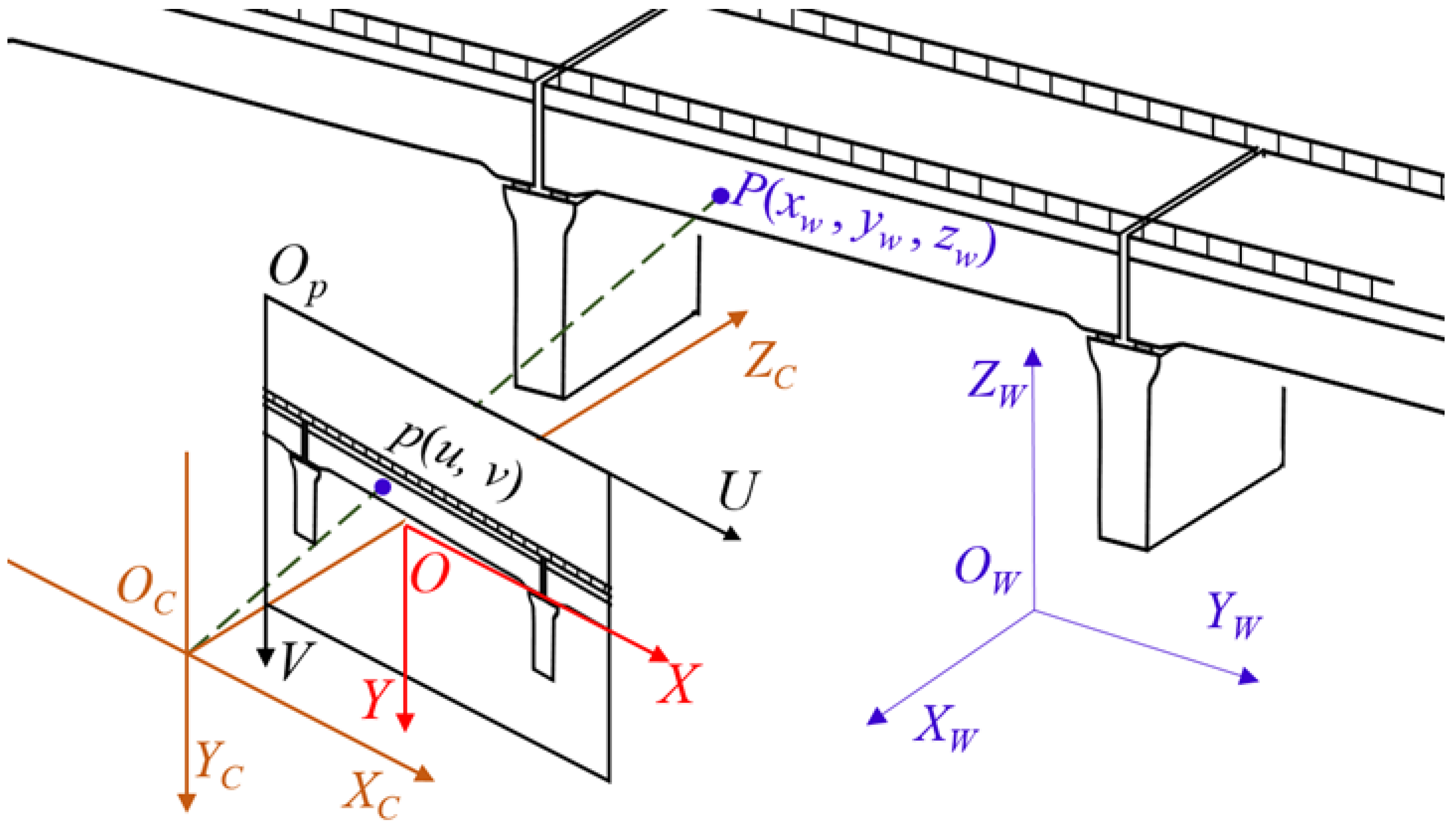
Due to its comprehensibility, the pinhole model is the most widely used one [31]. In this model, the world, camera, image, and pixel Cartesian coordinate systems are usually adopted, as shown in Figure 2. The world coordinate system, denoted as XwYwZw in Figure 2, is employed to describe the position of the camera and the target points; its coordinate origin can be set up at any location. The origin of the camera coordinate system, expressed as XcYcZc, is placed at the location of the camera lens optical center, and its Xc and Yc axes are along two sides of the camera image plane; so, the Zc axis of the camera coordinate system is along the principal optic axis of the camera. The image coordinate system, denoted as XY, commonly sets its origin at the intersection of the principal optic axis of the camera on the image, which is also called the principal point, and its X and Y axes are along two sides of the camera image plane. It should be noted that the world and camera coordinate systems are three-dimensional coordinate systems, while the image and pixel coordinate systems belong to plane coordinate systems.
Based on the pinhole model, the mathematical expression between the world coordinate system and the pixel coordinate system can be expressed as in [32,33]
( u v 1 ) = 1 z c [ f u 0 u 0 0 f v v 0 0 0 1 ] M 1 ( x c y c z c ) = 1 z c M 1 [ R | T ] M 2 ( x w y w z w 1 )
where the subscripts w and c denote the world and camera coordinate systems, respectively. M1 is the intrinsic matrix of the camera, which describes the characteristics of the camera. fu and fv are the scale factors in the U and V axes of the pixel coordinate system; u0 and v0 are the coordinates of the principal point in the pixel. M2 is the extrinsic matrix, which describes the camera’s pose in the world coordinate system, and R and T are the rotation matrix and translation vector, respectively, which can be further expressed as
R = [ r 11 r 12 r 13 r 21 r 22 r 23 r 31 r 32 r 33 ] T = ( T 1 T 2 T 3 )
where rij (i, j = 1, 2, 3) denotes the 3D rotation of the camera, and Ti (i = 1, 2, 3) describes the 3D location of the camera in the world coordinate system. If the matrices M1 and M2 are acquired, the relationship between the world coordinate system and the pixel coordinate system is established and the pinhole model is achieved.
Generally, the DIC algorithm requires the camera to remain stationary during measurement, and the principal optic axis of the camera is perpendicular to the target plane. Therefore, the world coordinate system can be conducted to coincide with the camera coordinate system. In this scenario, the extrinsic matrix can be expressed as
M 2 = ( 1 0 0 0 0 1 0 0 0 0 1 0 )
The relationship between the pixel coordinates and the world coordinates can be simplified as
( u v 1 ) = 1 z w [ f u 0 u 0 0 f v v 0 0 0 1 ] ( x w y w z w )
Thus, the real displacement of the object in the X and Y axes (Δxw, Δyw) can be estimated from the corresponding displacement in the image (Δu, Δv) by
{ Δ x w = z w / f u × Δ u Δ y w = z w / f v × Δ v
where zw/fu and zw/fv are scale factors between the actual physical length and the pixel length.
If the unknown parameters of zw/fu and zw/fv are acquired, the displacement of the object can be estimated using Equation (6). Note that the above process only involves the calculation of two internal parameters, which greatly simplifies the camera calibration process.

2.2. Displacement Measurement Using DIC and SURF for Nonstationary Cameras

If the UAV is employed as a platform for a camera during photographing, the assumption that the world coordinate system is coincident with the camera coordinate system is unavailable, and the wobble of the UAV will lead to the distortion of the images. That is, the displacement measurement can no longer be achieved only using Equation (6). Then, the extrinsic matrix M2 has to be extracted in real time; this problem can be avoided by converting the images to the same perspective using a homography matrix, which will be solved by the SURF and MSAC algorithm in this section.

2.2.1. Principle of Image Correction

Figure 3 shows the geometric relationship of the image planes before and after the camera movement. Point P (xw, yw, zw) in the world coordinate system is projected at p (u, v) on the image plane, and this point is projected at p′ (u′, v′) of the image plane after the camera movement. Generally, the relationship between (u, v) and (u′, v′) can be given as in [22]
{ u = h 11 u + h 12 v + h 13 h 31 u + h 32 v + 1 v = h 21 u + h 22 v + h 23 h 31 u + h 32 v + 1
where hij (i, j = 1, 2, 3 and i = j ≠ 3) are the parameters used to describe the distortion, and Equation (7) can be expressed in homogeneous coordinates as
( u v 1 ) = ( h 11 h 12 h 13 h 21 h 22 h 23 h 31 h 32 1 ) H ( u v 1 ) = H ( u v 1 )
where H is the homography matrix. As there are eight independent ratios or unknown parameters in Equation (8), at least four sets of non-collinear points in two image planes must be selected to calculate the H matrix by the least square algorithm, and the more points pairs selected, the more reliable the calculation result. Then, the image can be transformed to an image without camera movement using Equation (8); the fixed region of interest (FROI) in the target image and the reference image completely coincide, that is, the problem of camera wobble is addressed.

2.2.2. Feature Points Searching by SURF Algorithm

According to Equation (8), the solution of the matrix H lies in the search and matching of fixed points pairs. Due to its rotation invariance, scale invariance, high robustness and fast calculation, the SURF algorithm is adopted to track fixed points in this study. The SURF algorithm can be divided into four steps: feature detection, feature description, feature matching, and mismatching elimination.
For feature detection, an image pyramid is obtained by convolving the image with a series of box filters with gradually increasing size. Then, the determinant of the Hessian matrix for all points in the scale space is calculated; the extreme point among 26 neighbors of the selected point is found by non-maximum suppression in the 3 × 3 × 3 scale space, which is considered to be the SURF feature point. For feature description, a fan-shaped sliding window with an angle of 60 degrees and a radius of 6σ (σ is the size of filter) centered at current feature point is activated to sweep a circular region at s° increments (there is a total of 360/s sectors). At the same time, the total response of the Haar wavelet convolution weighted with Gaussian distribution in both the x and the y directions in the sector area is calculated to obtain the principal direction (the direction of the maximum responses) of the feature point. Next, a square sampling domain of size 20σ centered at the current feature point is selected, and it is split up into smaller 4 × 4 square sub-regions. The Haar wavelet response values in the horizontal and vertical directions (relative to the main direction) and their absolute values were calculated for each sub-region to form a 64-dimensional descriptor for the current feature point. For feature matching, the first and second steps are implemented separately for both the reference and the deformed images. The Euclidean distance d between all the SURF feature points in two images is calculated using the corresponding 64-dimensional descriptor. The minimum and the second-to-last minimum values of d are defined, respectively, as the shortest distance d1 and the second shortest distance d2. If the ratio η = d1/d2 is lower than a specified limit, a pair of matched points can be obtained. All the SURF feature points are obtained in this way and form the set of matched features. For mismatching elimination, the mapping between the two images is also calculated and then the m-estimator sample consensus (MSAC) [34] is introduced to remove the mismatches; this process is also known as matching point pair purification. The basic idea of MSAC is to select the transformation model satisfied by the most points along with the iterative computation; more detailed information about the MSAC can be found in reference [34].
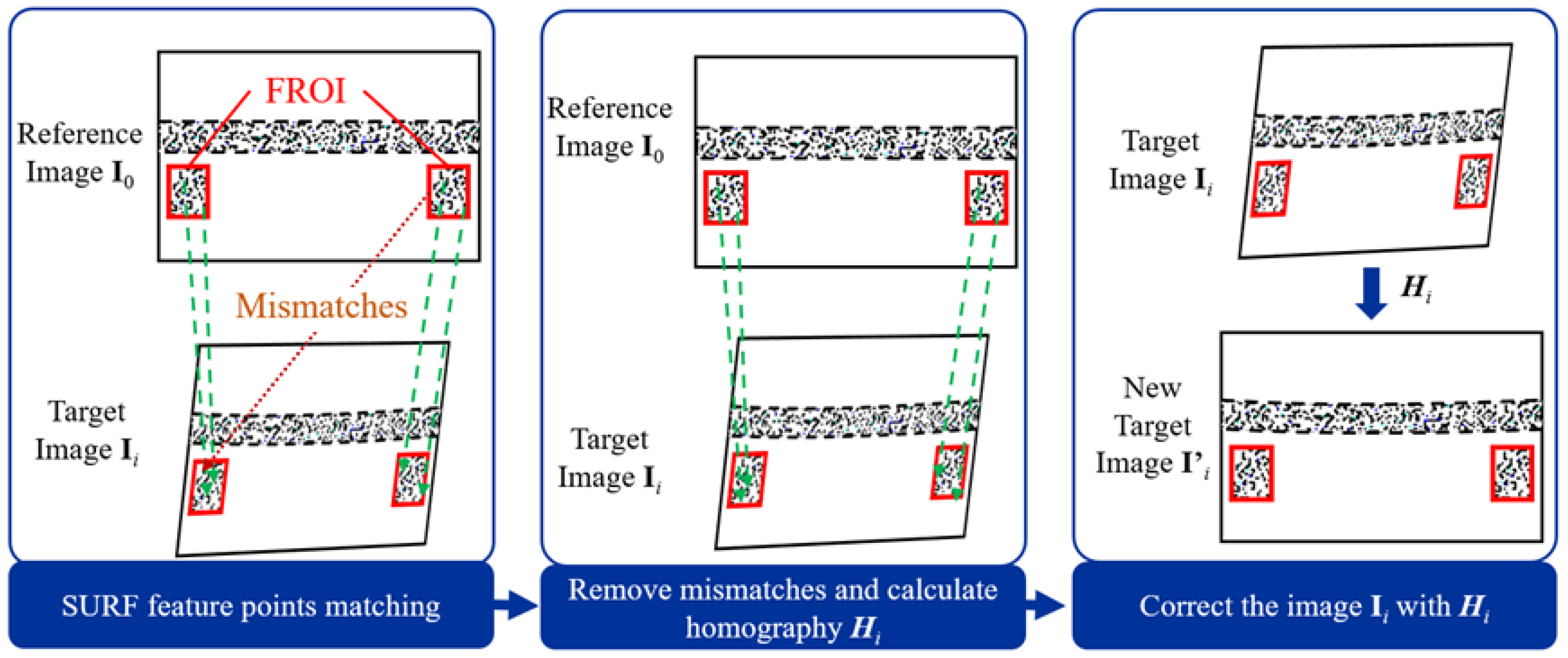
In order to eliminate the interference of the background points and ensure that there are enough fixed points, the speckle-pattern targets are placed in the measurement target plane as the fixed region of interest (FROI). In addition, the feature points are tracked in the FROI, respectively, that is, the feature points in each of the FROIs are matched and the MSAC algorithm is used to remove the mismatches. The homography matrix is then calculated using Equation (8) and used to correct the target image, as shown in Figure 4. Therefore, the problem of the camera movement when using the UAV as a platform is settled.

2.2.3. Auxiliary Reference Image Fabrication

According to Equations (2)–(6), it is necessary to ensure that the shooting angle of the reference image meets the requirement that the optical axis is perpendicular to the target plane. However, in the actual measurement condition, it is difficult to meet this requirement with a camera carried by a UAV; so, the first frame of the video should be rectified to the auxiliary reference image first, which meets the requirements of the traditional DIC algorithm. The specific steps are as follows:
(1) Determine the size factor. Select the first frame I of the video to make the reference image; select the top left corner, bottom right corner, bottom left corner, and top right corner of FROIs as points Ptl, Pbr, Pbl, Ptr in the world coordinate system. Calculate the scale factors zw/fu and zw/fv. For the values, for the sake of calculation, set zw/fu equal to zw/fv [35]
α = z w / f u = z w / f v = 1 2 ( l 1 Δ u 1 2 + Δ v 1 2 + l 2 Δ u 2 2 + Δ v 2 2 )
where l1 is the distance between Ptl and Pbr in the world coordinate system, l2 is the distance between Pbl and Ptr in the world coordinate system, (Δu1, Δv1) and (Δu2, Δv2) are the pixel coordinate differences corresponding to l1 and l2, respectively, as shown in Figure 5.
(2) Determine the coordinates of points Ptl, Pbr, Pbl, Ptr in the auxiliary reference image. Define point Ptl as the reference point; its pixel coordinate (ur, vr) in the reference image is the same as it is in image I; then, calculate the coordinates of Pbr, Pbl, Ptr in the reference image based on the coordinate difference between them and point Ptl in the world coordinate system and the size factor determined in the first step.
{ u i = u r + Δ x i α v i = v r + Δ y i α
where (ui, vi) is the pixel coordinate of points Pbr, Pbl, Ptr in the reference image, (ur, vr) is the pixel coordinate of point Ptl in image I, Δxi, Δyi are the coordinate difference between points Pbr, Pbl, Ptr and point Ptl in the world coordinate system.
(3) Obtain the auxiliary reference image. Calculate the homography matrix H according to the pixel coordinates of points Ptl, Pbr, Pbl, Ptr in image I and those obtained in the second step. Then, transform image I into the auxiliary reference image I0 with the matrix H.

2.2.4. Procedure of the Proposed Method

To address the camera movement issue when the UAV is implemented as a photograph platform, a coordinate transformation compensation method based on the SURF-enhanced camera calibration algorithm is presented, and then, the DIC algorithm can be implemented without considering the nonstationary camera. The major procedure of the proposed SCC-DIC method is as following:
Step 1: Determine the size factor and fabricate auxiliary reference image. First, determine the size factor according to Equation (9) and then fabricate a satisfactory auxiliary reference image I0 using the method proposed in Section 2.2.3.
Step 2: Track the feature points in the FROIs in both the auxiliary reference image I0 and the target image Ii, and calculate the homography matrix to correct the target image to form the new target image Ii, employing the method introduced in Section 2.2.2.
Step 3: Calculate the pixel displacement. Taking the corrected image Ii as the target image, apply the algorithm introduced in Section 2.1.1 to track the target points and calculate their pixel displacement.
Step 4: Calculate the physical displacement of the target points in ROI using the size factor obtained in Equation (9) and the method introduced in Section 2.1.2.
The procedure of the proposed method is shown in Figure 6.

3. Results

3.1. Numerical Simulation

3.1.1. Images and Camera Motions Simulation

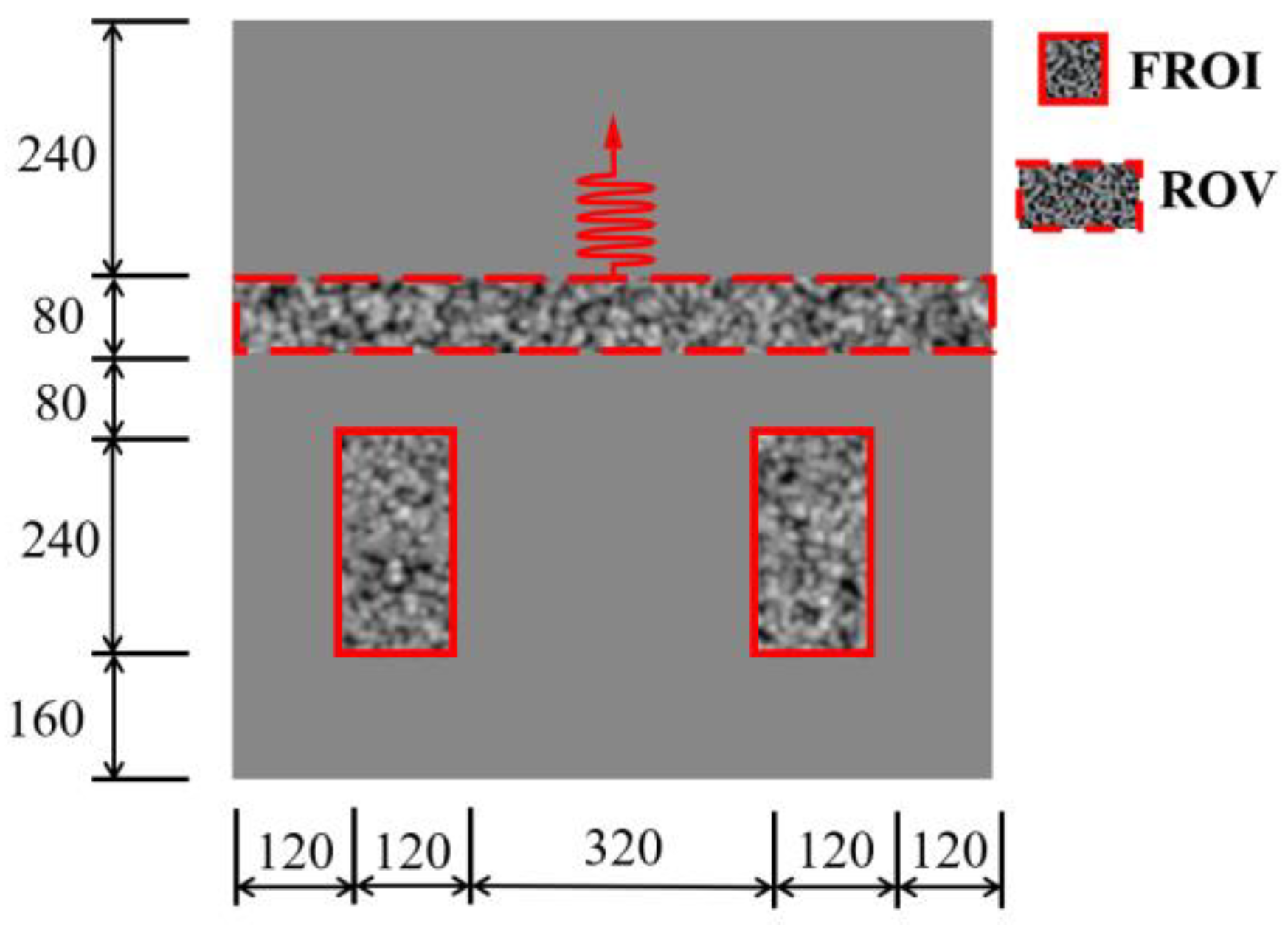
An area with 800 × 800 pixels is fabricated with speckle intensity, and then, this area is divided into three parts: two parts are used as FROIs, and the other part is used as a region of vibration (ROV), as shown in Figure 7. The ROV is assumed to vibrate along the V direction, and its displacement obeys v(t) = 16sin1.875t pixels, where t denotes time.
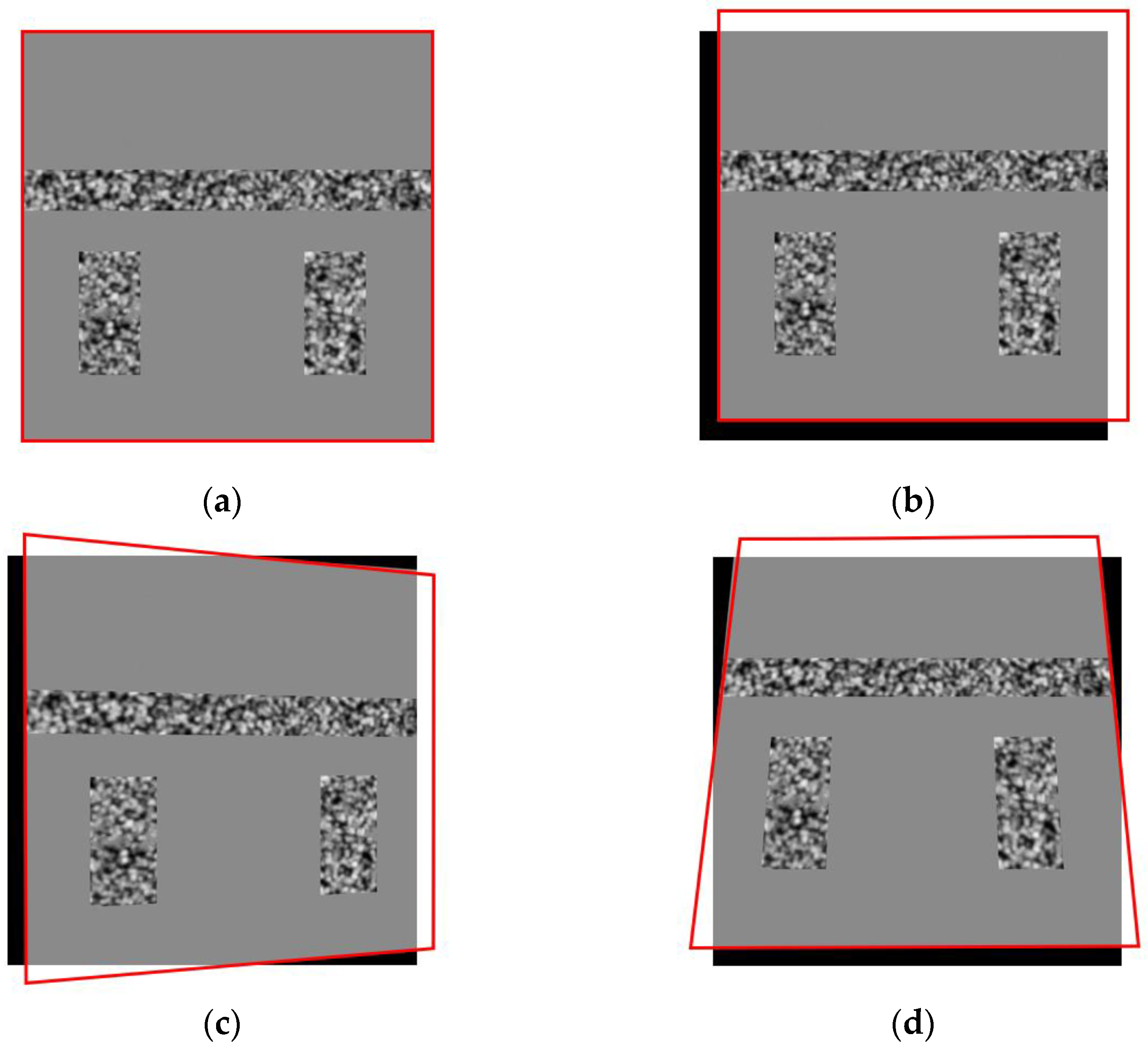
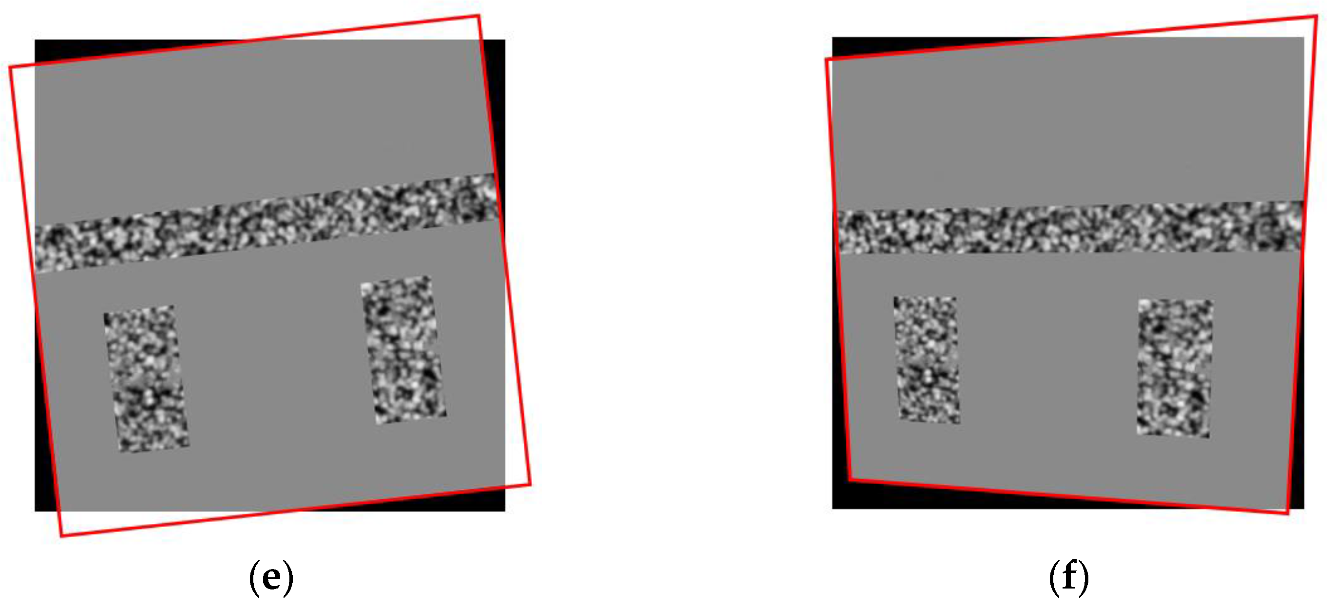
The sampling frequency of the camera is set as 30 Hz, and the camera is supposed to move during shooting, including translation, yaw, pitch, roll, and their combination, as shown in Figure 8. The camera moving cases are set as follows:
Case 1: The translation of the camera in both the U and V directions of the image is assumed as
f ( t ) = 60 6 × | mod ( 15 × ( t + 2 / 3 ) 40 ) 20 |
where t denotes time and mod (•) denotes the remainder operation.
Case 2: The camera will yaw with the transformation matrix TY as
T Y = P F · P MY 1
where PF is the coordinate of the fixed points, and PMY is the coordinate of the move points. They can be described as
{ P F = [ 1 1 1 1 800 1 800 1 1 800 800 1 ] P MY = [ 1 + f ( t ) 1 f ( t ) 1 1 + f ( t ) 800 + f ( t ) 1 800 + f ( t ) 1 + f ( t ) 1 800 + f ( t ) 800 f ( t ) 1 ]
Case 3: The camera will pitch with the transformation matrix TP as
{ T P = P F · P MP 1 P MP = [ 1 f ( t ) 1 + f ( t ) 1 1 + f ( t ) 800 + f ( t ) 1 800 + f ( t ) 1 + f ( t ) 1 800 f ( t ) 800 + f ( t ) 1 ]
where PMP is the coordinate of the move points.
Case 4: The camera is rotated around the center of the image as
θ = f ( t ) 4
where the unit of θ is degrees.
Case 5: The camera will wobble, which is the combination of case 1 to case 3, with the transformation matrix TW as:
{ T W = P F · P MW 1 P MW = [ 1 + 1.5 f ( x ) 1 + 1.5 f ( x ) 1 1 + 1.5 f ( x ) 800 + 0.5 f ( x ) 1 800 + 0.5 f ( x ) 800 + 0.5 f ( x ) 1 800 + 0.5 f ( x ) 1 + 1.5 f ( x ) 1 ]
where PMW is the coordinate of the move points.
In all the cases, the frequency of the camera motion is 0.375 Hz. It should be noted that in order to test the performance of the proposed SCC-DIC method under extreme conditions, the image distortion is very serious in the numerical simulation, and this degree of distortion almost does not occur in reality. To compare the proposed method, the feature points searching for Equation (8) using the DIC algorithm is implemented.
In the tracking process of the SURF feature points, the maximum distance threshold is set to 0.3, and the maximum number of iterations is 150,000. For the DIC algorithm, all the reference subsets are circular areas with a radius of 15 pixels, and the subset spacing is 10 pixels.

3.1.2. Results of Numerical Simulation

In order to verify the proposed method quantitatively, four indexes are introduced for comparison:
(1) The mean absolute error (MAE) of all the sampling points in each frame can be described as
M A E = i = 1 n | Δ v i Δ v | n
where Δvi is displacement of the ith sampling point in the ROV of the target image, and Δv is its truth value; n is the total number of sampling points in the ROV of the target image. MAE is used to metric the calculation accuracy, and the smaller its value, the higher the calculation accuracy.
(2) The root mean square (RMS) according to the calculation result and truth value is defined as
R M S = i = 1 n ( Δ v i Δ v ) 2 n
The RMS is suitable for assessing the calculation stability, and the smaller its value, the more the sampling points close to the true value, and the more stable the calculation.
(3) The mean value of MAE over all the images of the video (MMAE),
M M A E = 1 m M A E j m
where MAEj is represents the MAE of the jth frame image in the video, and m represents the number of frames in the video.
(4) The mean value of RMS over all the images of the video (MRMS),
M R M S = 1 m R M S j m
where RMSj represents the RMS of the jth frame image in the video.
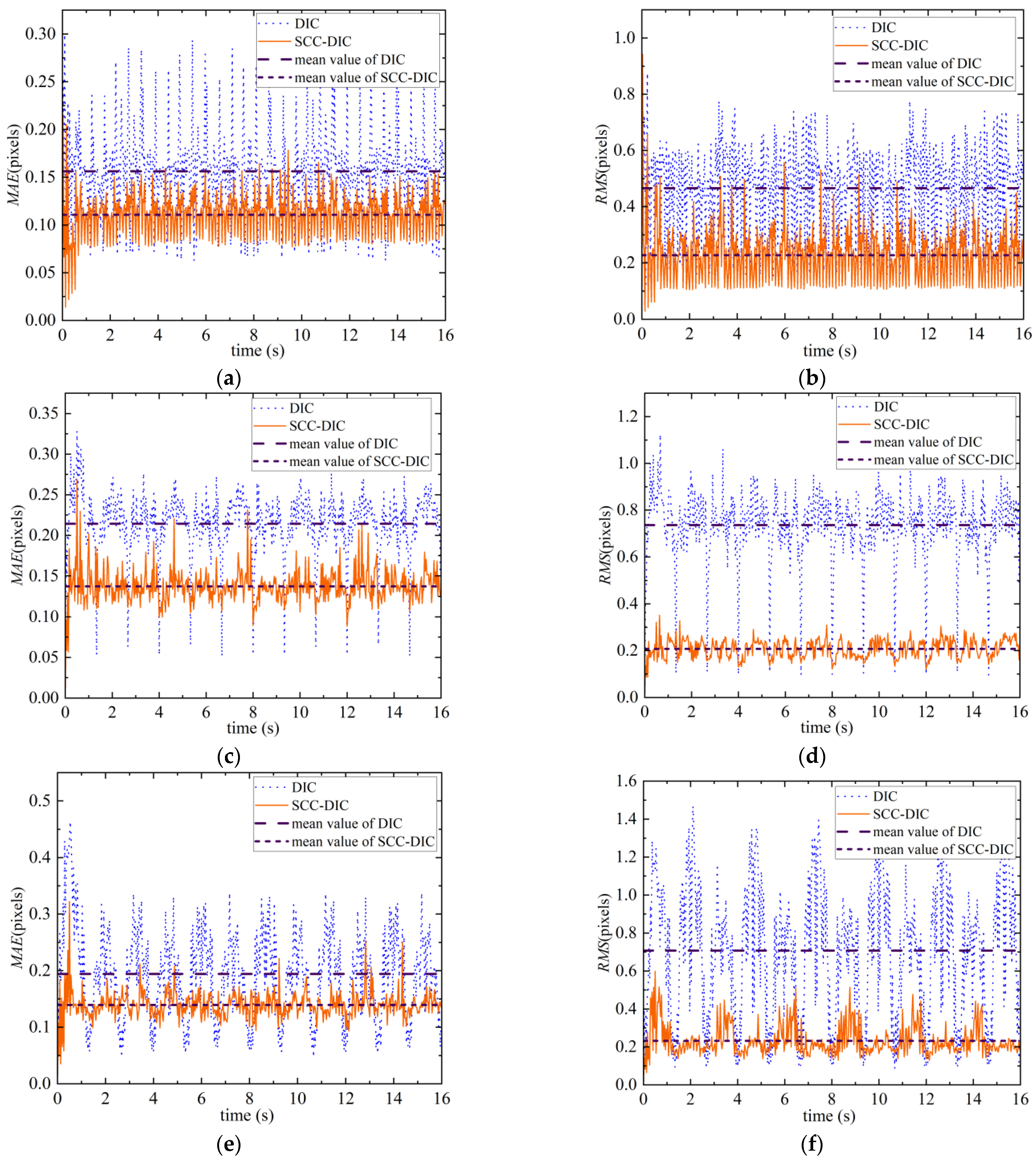
Taking the pixel at the upper left corner of the ROV as an example, its displacement time histories before and after camera calibration in all cases using the proposed method are shown in Figure 9.
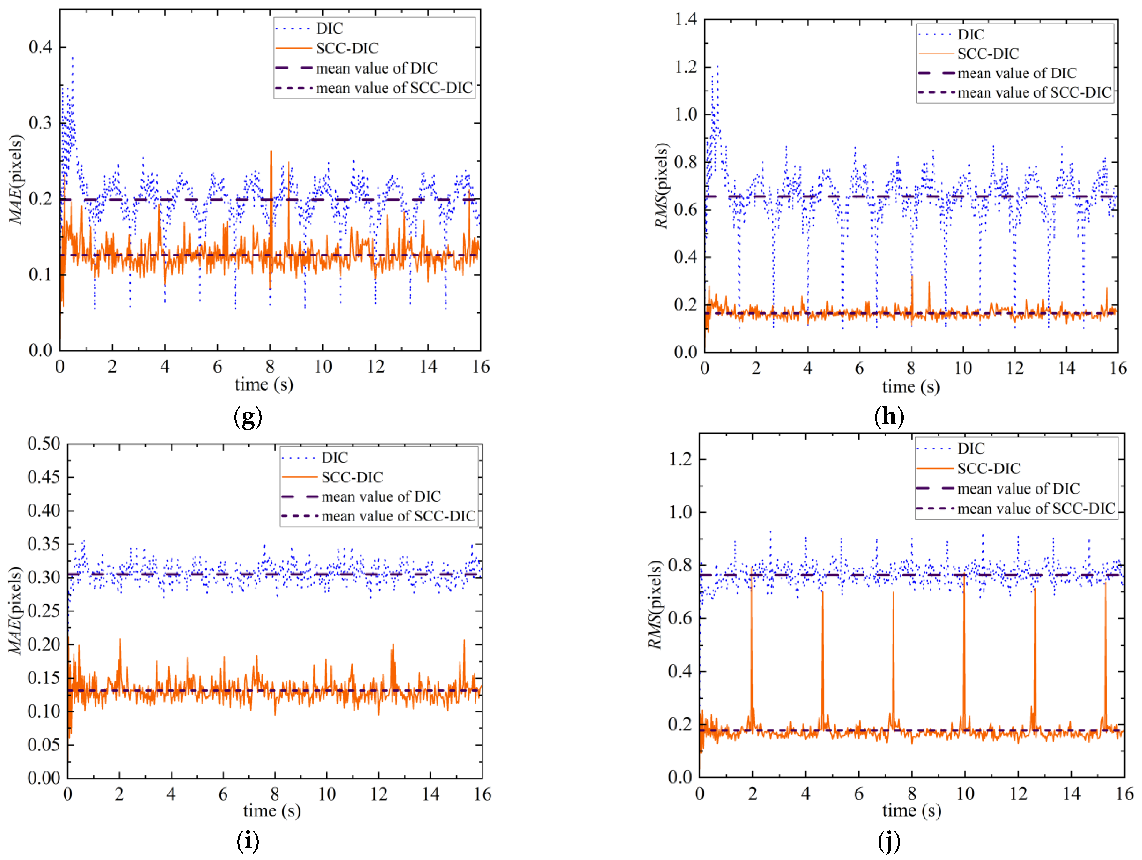
The MAE and RMS are calculated and shown in Figure 10. In all the cases, for the MAE value, method 1 performs better than method 2. From the perspective of MMAE, the MMAE of method 1 is lower than 0.15 pixels and lower than that of method 2 under corresponding circumstances. The same situation also occurs for the RMS value and MRMS. This means that the proposed method has excellent performance in both computational accuracy and computational stability.
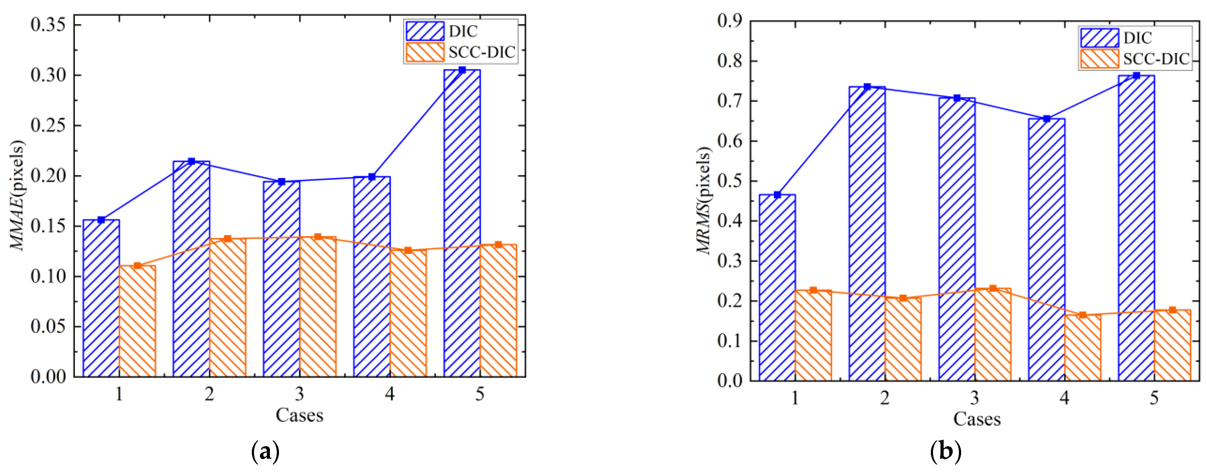
The MMAE and MRMS of the two methods in all the cases are compared, and the results are shown in Figure 11.
The MMAE and MRMS of the proposed method fluctuate more gently in different cases, which indicates that the proposed method is less sensitive to the camera wobble mode.
For the method proposed in this paper, the MMAE is the smallest in case 1 and larger in case 2 and case 3, and the MRMS is larger in case 2 and case 3.

3.2. Experiment Verification

3.2.1. Experiment Setting

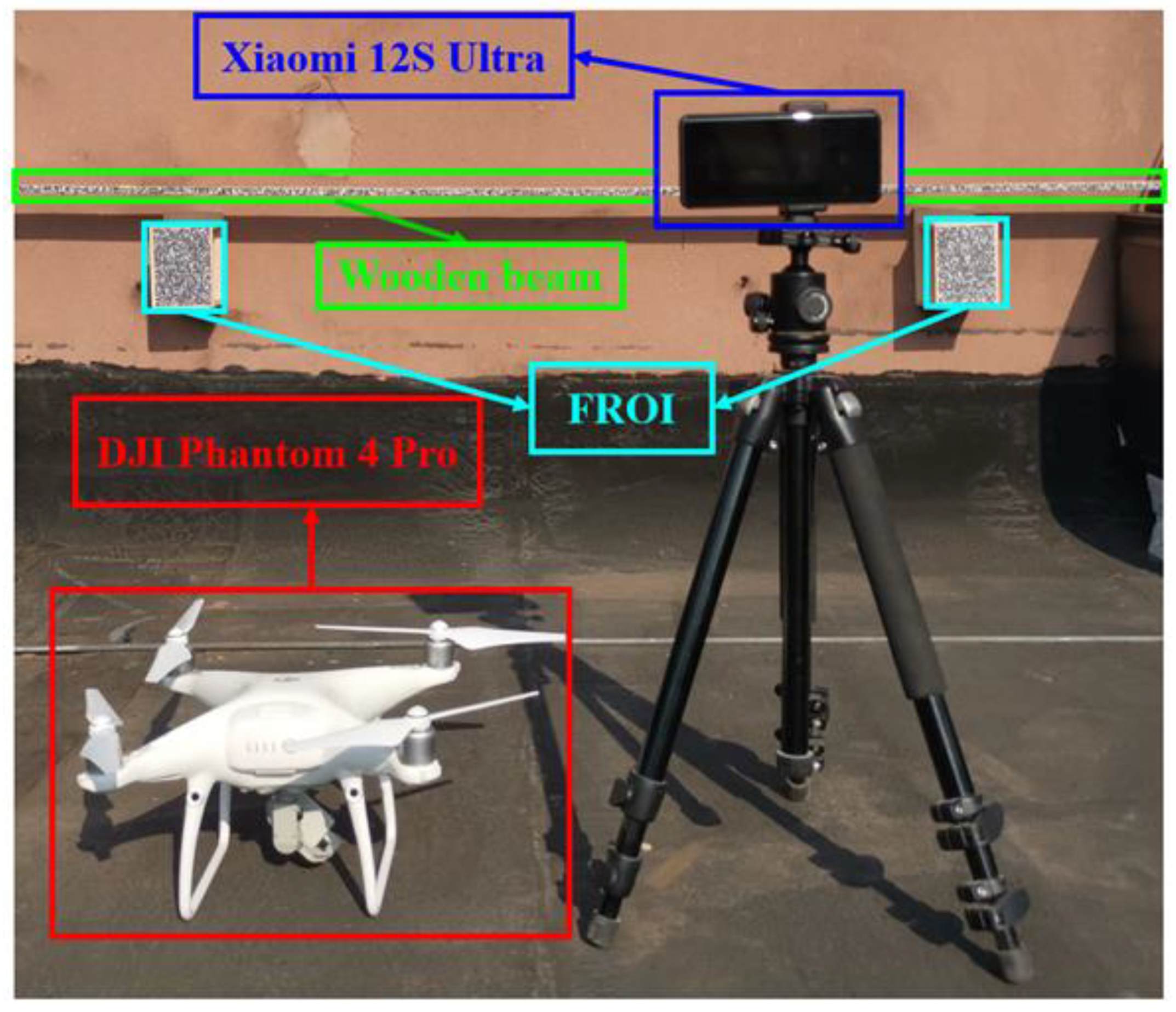
Two cameras were used to shoot videos of a simply supported wooden beam under free attenuation vibration. One camera was fixed (camera F) using a tripod for comparison, and the other camera (camera M) was attached on a UAV (DJI Phantom 4 Pro), as shown in Figure 12. The type of Camera F was the Xiaomi 12S Ultra, and camera M was the built-in camera of the UAV, and the resolution of both cameras was 3840 × 2160 pixels. The thickness, width, and length of the wooden beam were 10 mm, 50 mm, and 2000 mm, respectively. The speckle pattern was attached to one side of the beam, and two speckle icon targets with 125 mm × 90 mm were also set on the same side of the beam around two supports. These targets were adopted as FROIs, and the distance between the FROIs and the beam was 55 mm.
When the wooden beam was released with a random initial position, the two cameras began to shoot with a 30 Hz sampling frequency. As there was no synchronous acquisition device for these two cameras, the sampling beginning time of the two cameras was unsynchronized generally.

3.2.2. Experiment Results

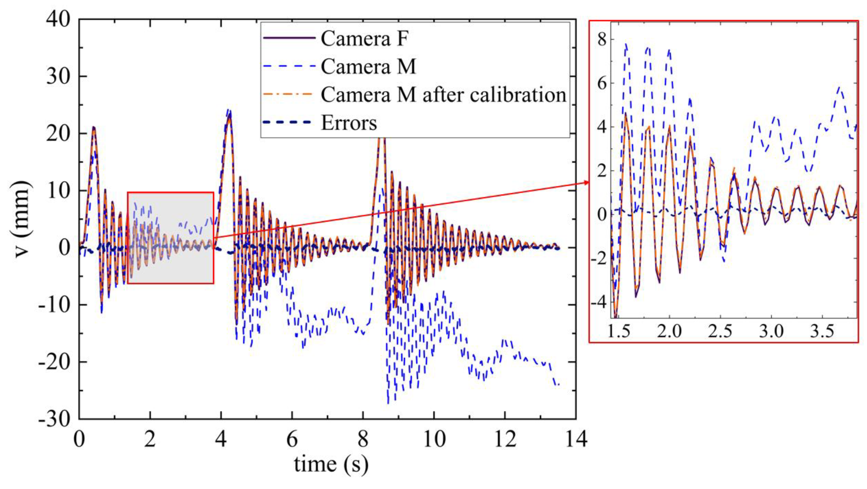
The method proposed in this paper was used to analyze the video shot by camera M (video M), and the DIC algorithm was used to analyze the video shot by camera F (video F). The displacement time–history curve estimated from the images of these two cameras is shown in Figure 13; the results obtained by the proposed method are in good agreement with those obtained by the fixed camera: the absolute errors were less than 1.2 mm, the relative error was less than 5% in the peak values, and the standard deviation was less than 0.34.
At the same time, the displacement estimator of camera M was obtained. Figure 14 shows the displacement of camera M and the absolute errors. The correlation coefficient between the error and the vibration amplitude of the beam is −0.574, and the correlation coefficient between the error and the displacement of camera M is 0.028.

4. Discussion

4.1. Discussion for Numerical Simulation

As seen in Figure 9, the proposed method can effectively calibrate the camera motions in all the cases and eliminate deviations. It can be seen that the calibrated displacement curve of the target point almost coincides with the true displacement curve, which indicates that the effect of SCC-DIC is excellent.
The results in Figure 10 show that the SCC-DIC method is superior to the traditional DIC method in terms of calculation accuracy and stability. The traditional DIC algorithm tracks the target point by calculating the correlation coefficient between the reference subset and the target subset, which requires that the image should not have too much distortion. However, the shake of the UAV will inevitably lead to great distortion of the image, which will inevitably lead to the decline of the accuracy of the DIC algorithm. In the SCC-DIC method, the SURF has scale invariance and rotation invariance, which makes up for the shortcomings of the DIC and makes the image correction and displacement solution more accurate; the auxiliary reference images make the corrected images meet the requirements of the DIC, which makes the accuracy of the calculation and the size calibration higher.
In case 5, the RMS of the proposed method will rise sharply at a certain moment, periodically, and the period is the same as that of the camera wobble. This indicates that there is an upper limit to the image correction ability of the proposed method, and the stability of the algorithm will decrease when the upper limit is exceeded.
The results in Figure 10 indicate that camera translation has less influence on the calculation accuracy; camera yaw and pitch have a greater impact on the calculation accuracy and the calculation stability. In practical applications, when the UAV is affected by wind or other external interference, the translation and yaw are commonly used to track the target. The highest accuracy will be acquired in the case of the UAV translation; both yaw and pitch will reduce the calculation accuracy and stability. Therefore, if the camera wobble can be controlled by the UAV manipulator, translation should be preferred instead of yaw to track the target.

4.2. Discussion for Experiment

The experimental results show that the absolute and relative errors calculated by SCC-DIC are both low, which indicates that this method can effectively eliminate the measurement errors caused by camera wobble in a test environment. As can be seen from Figure 13, the maximum error occurs at the moment when the beam vibration amplitude is maximum; accordingly, the correlation coefficient between the error and the vibration amplitude of the beam is −0.574; this indicates that the calculation error of this method may be related to the vibration amplitude of the beam. In contrast, the correlation coefficient between the error and the displacement of camera M is closer to zero, which indicates that the calculation accuracy of this method has low sensitivity to camera wobble in a practical application, which is what we would like to see.
In the SCC-DIC method, the main objective of step 2 is to correct the image so as to eliminate the error caused by the UAV wobble, and the main objective of step 3 is to calculate the pixel displacement of the target point. From the above discussion, it can be seen that step 2 has achieved remarkable results, and the source of error is more likely to come from step 3. Therefore, the following research will focus on step 3.
In summary, the proposed SCC-DIC method can effectively eliminate the measurement errors caused by camera wobble in a test environment, and it has low sensitivity to camera wobble in a practical application. So, it has the potential to be exploited in practical engineering structures.

5. Conclusions

A displacement measurement method using a camera on a UAV based on a SURF-enhanced feature point tracking and DIC algorithm, named as SCC-DIC, is proposed in this study. First, the image taken by the mobile camera is corrected by the SURF feature point tracking and the MSAC algorithm, and the deviation caused by UAV wobble is eliminated from the resolved homography matrix. Then, the DIC algorithm is implemented to calculate the displacement of the measured target. The numerical simulation results show that the mean absolute error and root mean square of the SCC-DIC method fluctuate around 0.13 pixels and 0.2 pixels in all cases, respectively; thus, the accuracy and the stability of the proposed method are verified. In addition, it was found that the deviation under UAV translation is smaller than that of the yaw. The experiment results show that the proposed method can effectively eliminate the error caused by the shaking of the UAV, and it has low sensitivity to camera wobble in a practical application; the deviation compared with the fixed camera was less than 1.2 mm; the relative error was less than 5% in the peak values; and the standard variance was less than 0.34.
The calculation error of the proposed method mainly comes from the third step of this method. Further research will focus on the third step to reduce the sensitivity of the calculation accuracy to the vibration amplitude.
The method proposed in this paper requires the fixed regions of interest and the target plane to be located on the same plane, which is not suitable for all practical applications. Therefore, further research will focus on the situation where the fixed regions of interest and the target plane are not coplanar.

Author Contributions

G.L.: conceptualization, methodology, writing—review and editing, supervision; C.H.: methodology, validation, formal analysis, investigation, writing—original draft, visualization; C.Z.: validation, investigation, writing—review; A.W.: validation, investigation, writing—review. All authors have read and agreed to the published version of the manuscript.

Funding

This work was supported by the National Key Research and Development Program (2021YFF0306302, 2021YFF0501004), the National Natural Science Foundation of China (52078084), and the National Natural Science Foundation of Chongqing (cstc2021jcyj-msxmX0623).

Institutional Review Board Statement

Not applicable.

Informed Consent Statement

Not applicable.

Data Availability Statement

Data are available on request to the authors.

Conflicts of Interest

The authors declare no conflict of interest.

References

  1. Wang, J.J.; Li, G.M. Study on Bridge Displacement Monitoring Algorithms Based on Multi-Targets Tracking. Future Internet 2020, 12, 9. [Google Scholar] [CrossRef] [Green Version]
  2. Won, J.; Park, J.W.; Park, J.; Shin, J.; Park, M. Development of a Reference-Free Indirect Bridge Displacement Sensing System. Sensors 2021, 21, 5647. [Google Scholar] [CrossRef] [PubMed]
  3. Xu, J.M.; Franza, A.; Marshall, A.M.; Losacco, N.; Boldini, D. Tunnel-framed building interaction: Comparison between raft and separate footing foundations. Geotechnique 2021, 71, 631–644. [Google Scholar] [CrossRef]
  4. Liu, G.; Li, M.Z.; Mao, Z.; Yang, Q.S. Structural motion estimation via Hilbert transform enhanced phase-based video processing. Mech. Syst. Signal Process. 2022, 166, 108418. [Google Scholar] [CrossRef]
  5. Lee, J.; Lee, K.-C.; Jeong, S.; Lee, Y.-J.; Sim, S.-H. Long-term displacement measurement of full-scale bridges using camera ego-motion compensation. Mech. Syst. Signal Process. 2020, 140, 106651. [Google Scholar] [CrossRef]
  6. Luo, J.; Liu, G.; Huang, Z.M.; Law, S.S. Mode shape identification based on Gabor transform and singular value decomposition under uncorrelated colored noise excitation. Mech. Syst. Signal Process. 2019, 128, 446–462. [Google Scholar] [CrossRef]
  7. Huang, S.; Duan, Z.; Wu, J.; Chen, J. Monitoring of Horizontal Displacement of a Super-Tall Structure During Construction Based on Navigation Satellite and Robotic Total Station. J. Tongji Univ. 2022, 50, 138–146. [Google Scholar]
  8. Kim, K.; Sohn, H. Dynamic displacement estimation for longspan bridges using acceleration and heuristically enhanced displacement measurements of realtime kinematic global navigation system. Sensors 2020, 20, 5092. [Google Scholar] [CrossRef]
  9. Yu, J.; Meng, X.; Yan, B.; Xu, B.; Fan, Q.; Xie, Y. Global Navigation Satellite System-based positioning technology for structural health monitoring: A review. Struct. Control Health Monit. 2020, 27, e2467. [Google Scholar] [CrossRef] [Green Version]
  10. Du, W.K.; Lei, D.; Bai, P.X.; Zhu, F.P.; Huang, Z.T. Dynamic measurement of stay-cable force using digital image techniques. Measurement 2020, 151, 107211. [Google Scholar] [CrossRef]
  11. Mousa, M.A.; Yussof, M.M.; Udi, U.J.; Nazri, F.M.; Kamarudin, M.K.; Parke, G.A.R.; Assi, L.N.; Ghahari, S.A. Application of Digital Image Correlation in Structural Health Monitoring of Bridge Infrastructures: A Review. Infrastructures 2021, 6, 176. [Google Scholar] [CrossRef]
  12. Kumarapu, K.; Mesapam, S.; Keesara, V.R.; Shukla, A.K.; Manapragada, N.; Javed, B. RCC Structural Deformation and Damage Quantification Using Unmanned Aerial Vehicle Image Correlation Technique. Appl. Sci. 2022, 12, 6574. [Google Scholar] [CrossRef]
  13. Liang, Z.; Zhang, J.; Qiu, L.; Lin, G.; Yin, F. Studies on deformation measurement with non-fixed camera using digital image correlation method. Measurement 2021, 167, 108139. [Google Scholar] [CrossRef]
  14. Liu, G.; Li, M.; Zhang, W.; Gu, J. Subpixel Matching Using Double-Precision Gradient-Based Method for Digital Image Correlation. Sensors 2021, 21, 3140. [Google Scholar] [CrossRef]
  15. Malesa, M.; Szczepanek, D.; Kujawińska, M.; Świercz, A.; Kołakowski, P. Monitoring of civil engineering structures using Digital Image Correlation technique. EPJ Web Conf. 2010, 6, 31014. [Google Scholar] [CrossRef] [Green Version]
  16. Molina-Viedma, A.J.; Pieczonka, L.; Mendrok, K.; Lopez-Alba, E.; Diaz, F.A. Damage identification in frame structures using high-speed digital image correlation and local modal filtration. Struct. Control Health Monit. 2020, 27, e2586. [Google Scholar] [CrossRef]
  17. Ribeiro, D.; Santos, R.; Cabral, R.; Saramago, G.; Montenegro, P.; Carvalho, H.; Correia, J.; Calçada, R. Non-contact structural displacement measurement using Unmanned Aerial Vehicles and video-based systems. Mech. Syst. Signal Process. 2021, 160, 107869. [Google Scholar] [CrossRef]
  18. Hoskere, V.; Park, J.-W.; Yoon, H.; Spencer, B.F. Vision-Based Modal Survey of Civil Infrastructure Using Unmanned Aerial Vehicles. J. Struct. Eng. 2019, 145, 04019062. [Google Scholar] [CrossRef]
  19. Garg, P.; Moreu, F.; Ozdagli, A.; Taha, M.R.; Mascarenas, D. Noncontact Dynamic Displacement Measurement of Structures Using a Moving Laser Doppler Vibrometer. J. Bridge Eng. 2019, 24, 04019089. [Google Scholar] [CrossRef]
  20. Hatamleh, K.S.; Ma, O.; Flores-Abad, A.; Xie, P. Development of a Special Inertial Measurement Unit for UAV Applications. J. Dyn. Syst. Meas. Control 2013, 135, 011003. [Google Scholar] [CrossRef]
  21. Yoon, H.; Shin, J.; Spencer, B.F. Structural Displacement Measurement Using an Unmanned Aerial System. Comput.-Aided Civ. Infrastruct. Eng. 2018, 33, 183–192. [Google Scholar] [CrossRef]
  22. Yoneyama, S.; Ueda, H. Bridge Deflection Measurement Using Digital Image Correlation with Camera Movement Correction. Mater. Trans. 2012, 53, 285–290. [Google Scholar] [CrossRef] [Green Version]
  23. Chen, G.; Liang, Q.; Zhong, W.; Gao, X.; Cui, F. Homography-based measurement of bridge vibration using UAV and DIC method. Measurement 2021, 170, 108683. [Google Scholar] [CrossRef]
  24. Wang, L.P.; Bi, S.L.; Li, H.; Gu, Y.G.; Zhai, C. Fast initial value estimation in digital image correlation for large rotation measurement. Opt. Lasers Eng. 2020, 127, 105838. [Google Scholar] [CrossRef]
  25. Bay, H.; Ess, A.; Tuytelaars, T.; Van Gool, L. Speeded-Up Robust Features (SURF). Comput. Vis. Image Underst. 2008, 110, 346–359. [Google Scholar] [CrossRef]
  26. Blaber, J.; Adair, B.; Antoniou, A. Ncorr: Open-Source 2D Digital Image Correlation Matlab Software. Exp. Mech. 2015, 55, 1105–1122. [Google Scholar] [CrossRef]
  27. Bai, X.; Yang, M. UAV based accurate displacement monitoring through automatic filtering out its camera’s translations and rotations. J. Build. Eng. 2021, 44, 102992. [Google Scholar] [CrossRef]
  28. Baldi, A.; Santucci, P.M.; Bertolino, F. Experimental assessment of noise robustness of the forward-additive, symmetric-additive and the inverse-compositional Gauss-Newton algorithm in digital image correlation. Opt. Lasers Eng. 2022, 154, 107012. [Google Scholar] [CrossRef]
  29. Shao, X.; He, X. Statistical error analysis of the inverse compositional gauss-newton algorithm in digital image correlation. In Proceedings of the 1st Annual International Digital Imaging Correlation Society 2016, Philadelphia, PA, USA, 7–10 November 2016; Springer: Cham, Switzerland, 2017; pp. 75–76. [Google Scholar]
  30. Passieux, J.-C.; Bouclier, R. Classic and inverse compositional Gauss-Newton in global DIC. Int. J. Numer. Methods Eng. 2019, 119, 453–468. [Google Scholar] [CrossRef] [Green Version]
  31. Juarez-Salazar, R.; Zheng, J.; Diaz-Ramirez, V.H. Distorted pinhole camera modeling and calibration. Appl. Opt. 2020, 59, 11310–11318. [Google Scholar] [CrossRef]
  32. Long, L.; Dongri, S. Review of Camera Calibration Algorithms. Adv. Intell. Syst. 2019, 924, 723–732. [Google Scholar]
  33. Zhu, Y.; Wu, Y.; Zhang, Y.; Qu, F. Multi-camera System Calibration of Indoor Mobile Robot Based on SLAM. In Proceedings of the 2021 3rd International Conference on Machine Learning, Big Data and Business Intelligence (MLBDBI), Taiyuan, China, 3–5 December 2021; pp. 240–244. [Google Scholar]
  34. Wu, S.L.; Zeng, W.K.; Chen, H.D. A sub-pixel image registration algorithm based on SURF and M-estimator sample consensus. Pattern Recognit. Lett. 2020, 140, 261–266. [Google Scholar] [CrossRef]
  35. Swamidoss, I.N.; Bin Amro, A.; Sayadi, S. An efficient low-cost calibration board for Long-wave infrared (LWIR) camera. In Proceedings of the Electro-Optical and Infrared Systems: Technology and Applications XVII, Edinburgh, UK, 21–24 September 2020. [Google Scholar] [CrossRef]
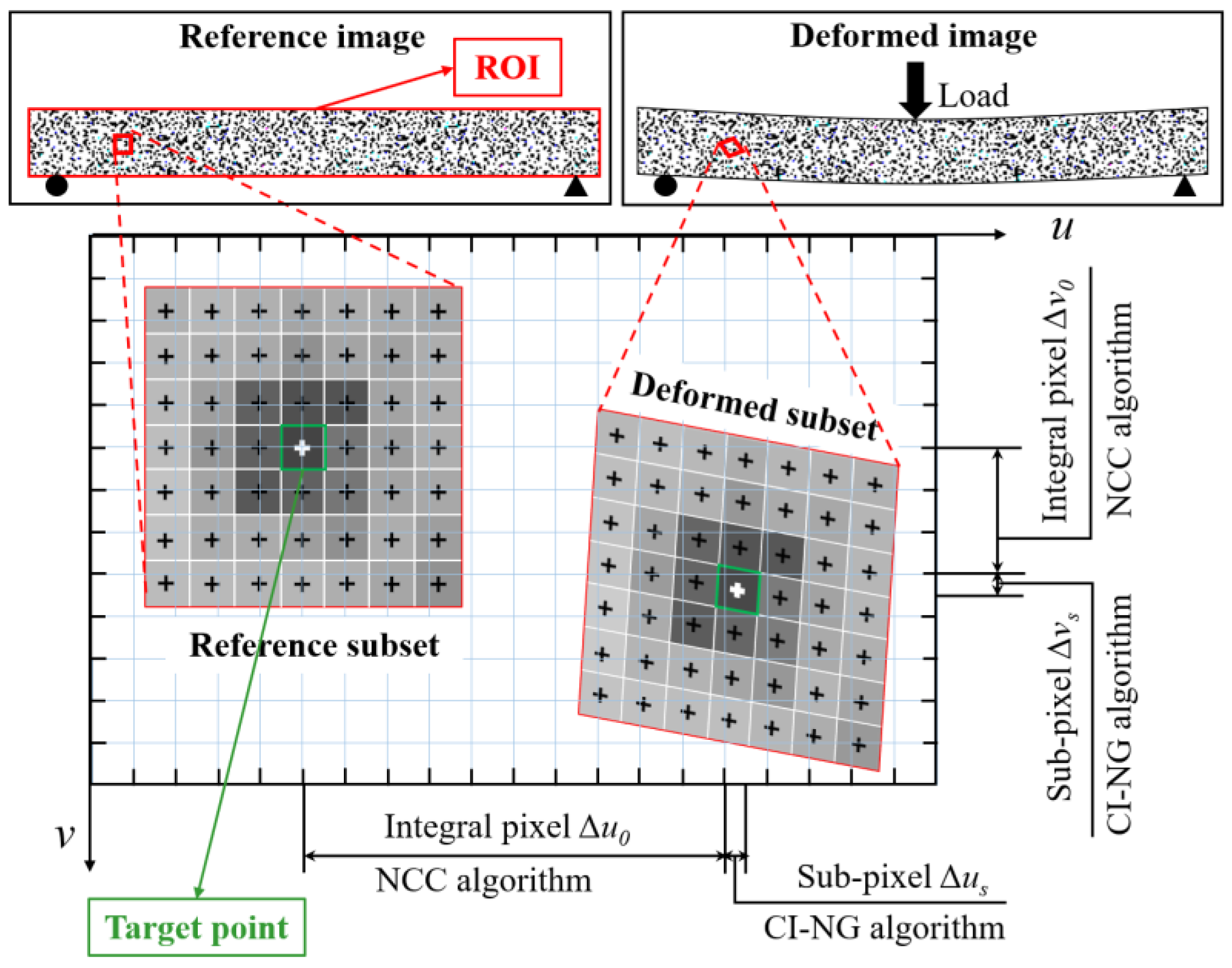
Figure 1. Digital image correlation (DIC) algorithm.
Remotesensing 14 06008 g001
Figure 2. Pinhole camera model and the four coordinate systems.
Remotesensing 14 06008 g002
Figure 3. Geometrical relationship between image planes before and after the camera movement.
Remotesensing 14 06008 g003
Figure 4. Feature points searching using the SURF and MSAC algorithm.
Remotesensing 14 06008 g004
Figure 5. Calculation of size factor.
Remotesensing 14 06008 g005
Figure 6. Procedure of the proposed method.
Remotesensing 14 06008 g006
Figure 7. Video images (units: pixel).
Remotesensing 14 06008 g007
Figure 8. Camera wobble modes and corresponding image transformation: (a) still; (b) translation; (c) yaw; (d) pitch; (e) roll; (f) combination.
Remotesensing 14 06008 g008aRemotesensing 14 06008 g008b
Figure 9. Displacement time–history of the upper left corner point before nd after camera calibration in all cases: (a) case 1; (b) case 2; (c) case 3; (d) case 4; (e) case 5.
Remotesensing 14 06008 g009
Figure 10. MAE and RMS of the two methods in all cases: (a) MAE of the two methods in case 1; (b) RMS of the two methods in case 1; (c) MAE of the two methods in case 2; (d) RMS of the two methods in case 2; (e) MAE of the two methods in case 3; (f) RMS of the two methods in case 3; (g) MAE of the two methods in case 4; (h) RMS of the two methods in case 4; (i) MAE of the two methods in case 5; (j) RMS of the two methods in case 5.
Remotesensing 14 06008 g010aRemotesensing 14 06008 g010b
Figure 11. (a) MMAE of the two methods; (b) MRMS of the two methods.
Remotesensing 14 06008 g011
Figure 12. Experiment setting.
Remotesensing 14 06008 g012
Figure 13. Displacement time–history curve.
Remotesensing 14 06008 g013
Figure 14. Errors and displacement of camera M.
Remotesensing 14 06008 g014
Publisher’s Note: MDPI stays neutral with regard to jurisdictional claims in published maps and institutional affiliations.