Abstract
As a potential external calibration reference for spaceborne microwave sounding instruments, accurate and reliable information of lunar disk-averaged radiance at millimeter band are important and fundamental. Based on study for 2-D lunar scans of the Advanced Technology Microwave Sounder (ATMS) on board the NOAA-20 satellite, the lunar radiance spectrum from 23 to 183 GHz at full moon phase has been reported in our previous work. In this study, the performance of a lunar microwave radiative transfer model (RTM) developed by Keihm was investigated (cited as Keihm model in this paper) . By taking the ATMS observations as the reference truth, the surface emissivity in the lunar RTM can be calibrated. The calibrated RTM model was then evaluated by independent satellite observation data sets from AMSU (Advanced Microwave Sounding Unit) and MHS (Microwave Humidity Sounder) instruments on several NOAA satellites. Results show that with the calibrated model, significant improvement can be made to reduce the uncertainties in the lunar microwave RTM simulations at millimeter wavelengths.
1. Introduction
Lunar surface reflectance and emissivity properties are extremely stable, and can be known to high precision. Several recent papers have discussed the potential of using the Moon as an international standard traceable calibration target for spaceborne microwave sounding radiometers [1,2,3]. For lunar calibration of microwave sounding instruments, accurate knowledge for the variation of lunar brightness temperature () with Moon phase angle over a wide range of detection frequencies are fundamental. In recent years, with the observations obtained from the Diviner Lunar Radiometer Experiment instrument (DLRE) onboard the Lunar Reconnaissance Orbiter, improvements have been made to the thermal model for lunar surface and subsurface temperatures simulations [4]. The lunar thermal temperature profile can now be simulated with a high accuracy when compared with ground truth [5]. Microwave radiation can penetrate to lunar sub-surface; thus the microwave thermal emission in terms of brightness temperature can be quite different from surface temperature. Efforts have been made to simulate the lunar microwave radiation since 1960s [6,7,8,9]. Although some improvements have been made in recent years based on lunar orbit optical and microwave satellite observations [10,11], there are still some difficulties for accurate lunar microwave emission model development in millimeter band. One of the major challenges is the uncertainty in the lunar regolith electrical absorption properties. Recently we reported the lunar disk averaged radiance spectrum from 23 to 183 GHz for full moon phase based on analysis of 2-D lunar scans of the Advanced Technology Microwave Sounder (ATMS) on board the NOAA-20 satellite [12]. The overall goal of this study is to calibrate the lunar RTM model by comparing the simulated lunar at millimeter band with the ATMS observations. The Radiative Transfer Model developed by Keihm was used for this purpose [9], with input thermal profiles generated from a 1-D heat conduction model developed by Hayne et al. [5]. In this paper, Section 2 introduces the lunar microwave RTM model. Lunar disk-averaged simulation results are presented in Section 3. Section 4 describes the model calibration, based on the comparison results between simulations and satellite observations. Section 5 presents the validation results of the calibrated model. Summary and conclusion are included in Section 6.
2. Lunar Microwave Radiative Transfer Model
Microwave brightness temperature of lunar emission can be calculated as convolution of microwave electrical loss with lunar regolith temperature profile over different depths z () [11]:
The discrete form can be written as weighting sum of thermal temperature at each layer:
with weighting coefficient . In equation above, is the surface emissivity, and is the observable brightness temperature. is the physical temperature of the lunar regolith in ith layer. is the emergence angle. is the wavelength-, depth- and temperature dependent microwave absorption. For low loss dielectric materials such as lunar regolith, the coefficient can be expressed in terms of the complex permittivity and the wavelength as below [9]:
In equation above, is the wavelength, is the real part of the dielectric constant of lunar regolith, the loss tangent parameter is the ratio of the imaginary to real parts of the dielectric constant. The details of the model parameters can be found in [9]. The physical temperature profile, , can be derived by solving the one-dimension heat equation:
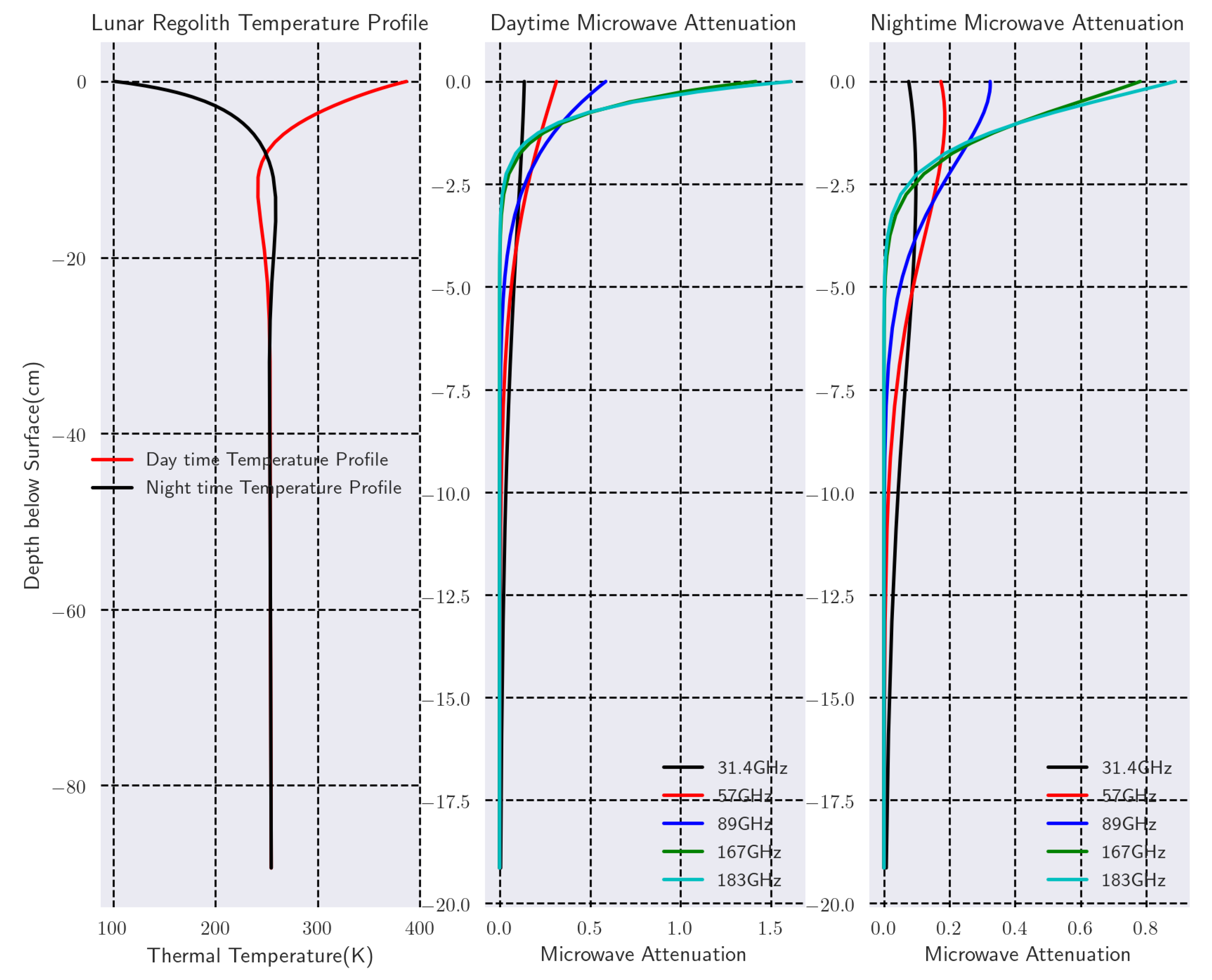
where is the density of the lunar regolith, is the specific heat, K is the thermal conductivity. The details of the numerical solution of Equation (3) and the model parameters can be found in [5]. For this study, a profile with 23 layers extending from the lunar surface to 98 cm under the regolith was generated at each latitude of the Moon from −90° to 90° . Figure 1 shows the input temperature profile for local noon and mid night at the center of lunar front disk. Also presented are the corresponding microwave electric loss weights at different frequencies. It is seen that while the higher frequency is much more sensitive to the microwave emission at the near-surface layers above 2.5 cm, the emission from deeper layer have more contribution for the top of surface (TOS) of lower frequency bands, most notably for the night time microwave radiation when there is no incident solar flux.
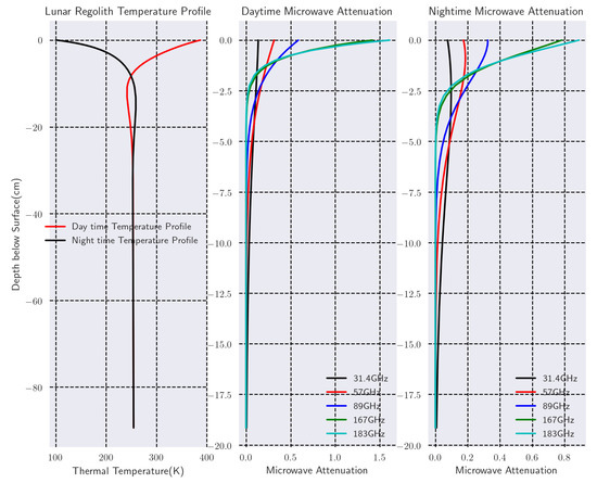
Figure 1.
The daytime and nightime lunar regolith temperature profiles and microwave layer weighting coefficients () profiles at selected ATMS frequencies.
3. Lunar Disk Microwave Brightness Temperature Simulations
As discussed before, currently there is no practical model to calculate the effective surface emissivity of lunar regolith at millimeter band. Almost all previous analyses of lunar microwave emission have assumed a locally plane-parallel surface and a Fresnel emissivity. For reference convenience, the Fresnel equations used for calculate the surface reflectivity coefficients in Keihm’s RTM model is listed as below:
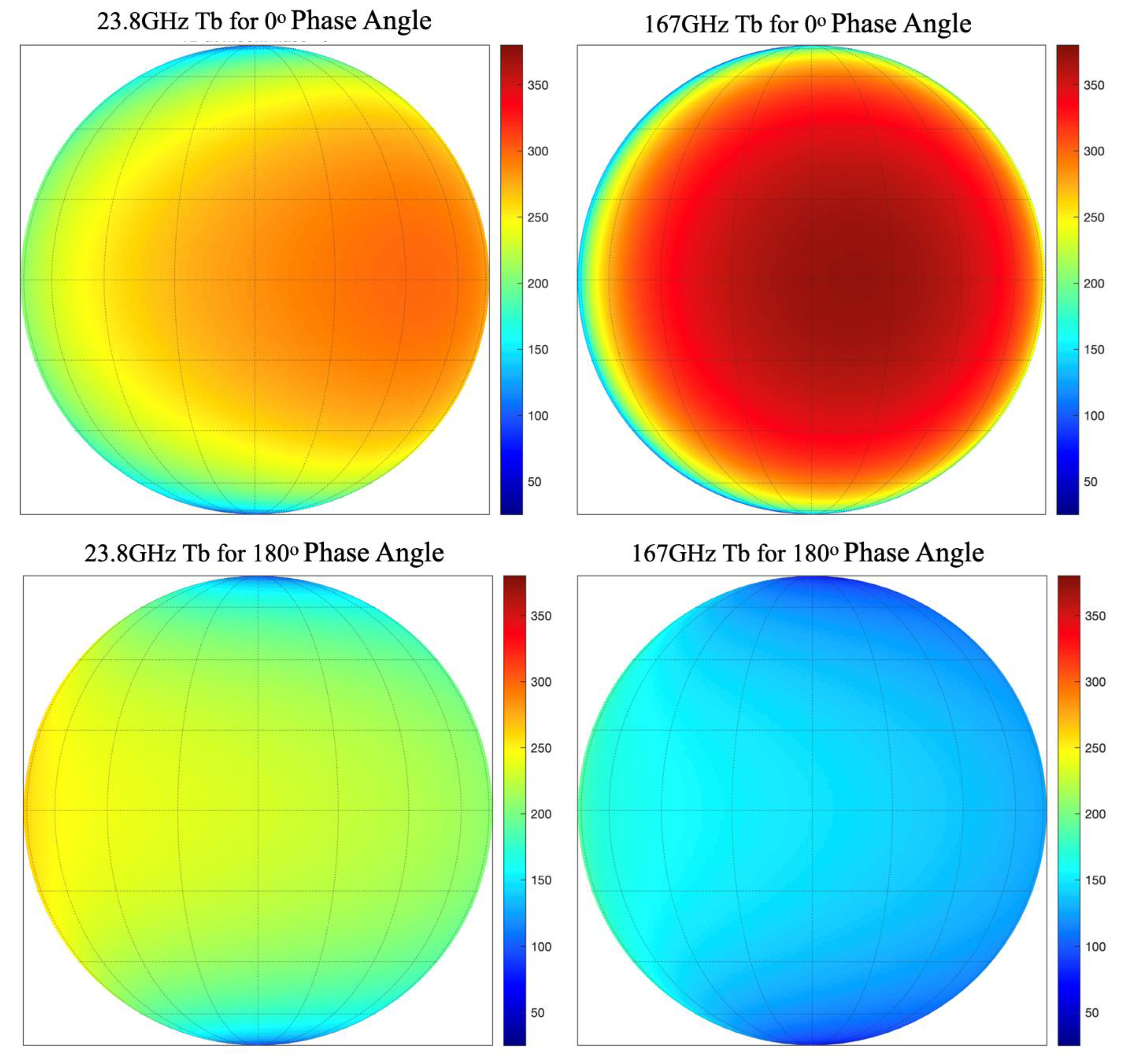
where is the dielectric constant of the lunar regolith, and are the refraction angle and incidence angle correspondently. As pointed in [9], realistic departure from this assumption, both large-scale and small scale roughness can contribute to brightness temperature changes. For simulations in this section, to reduce the uncertainty when Fresnel reflection function is used, the emissivity in Equation (2) was set to 1 and only the “black body” emission will be simulated. The effective surface emissivity will be calibrated by satellite observations. Figure 2 shows the simulated lunar disk front side microwave color maps for 23.8 GHz (12.6 mm) and 167 GHz (1.8 mm). Both simulations at full moon (0°) and new moon (180° phase angle) are presented with resolution of 1° by 1° for comparison purpose. It is seen that while the distribution of microwave on lunar disk is impacted by latitude and local phase angle, there is significant asymmetry in the distribution at low frequency. Also noticed is that compare to higher frequency, the in low frequency is colder in full moon and warmer in new moon.
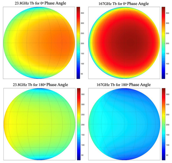
Figure 2.
The simulated front side lunar disk of full Moon(local noon) and new moon (local mid night) for 23.8 and 167 GHz.
The disk-averaged can then be calculated as weighting sum of global as below:
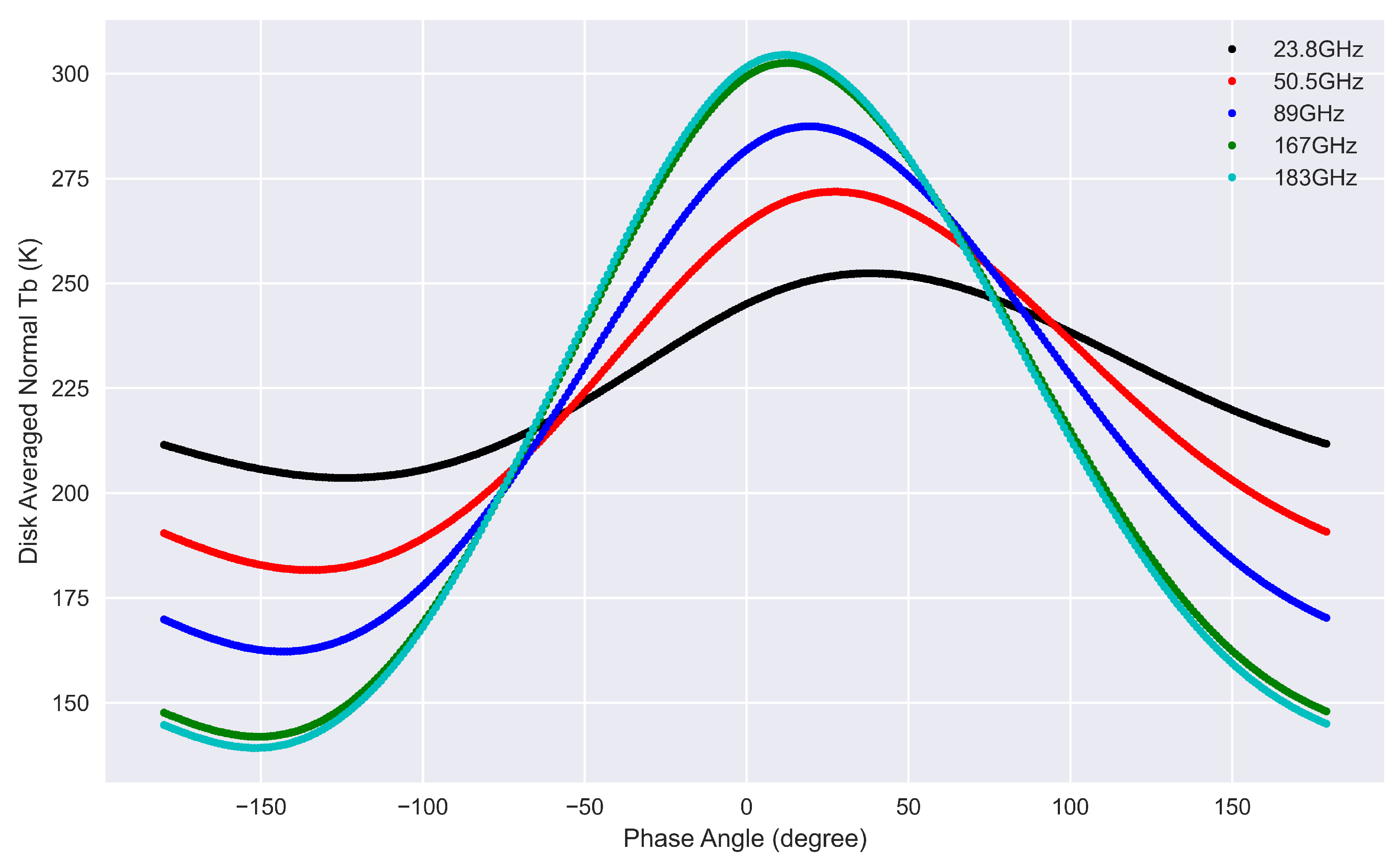
where the weights . The dynamic variation with phase angle and the asymmetry can be clearly seen in disk-averaged , as shown in Figure 3. The asymmetry can be explained by the larger phase lag in the longer wavelength due to the penetration depths characteristic of microwave radiation [6,9,13,14]. The phase lag angle decreases from 36° in 23.8 GHz (12.6 mm), 16° in 89 GHz to 9° in 183 GHz (1.6 mm), which are close with those derived from satellite observations in our previous study [15].
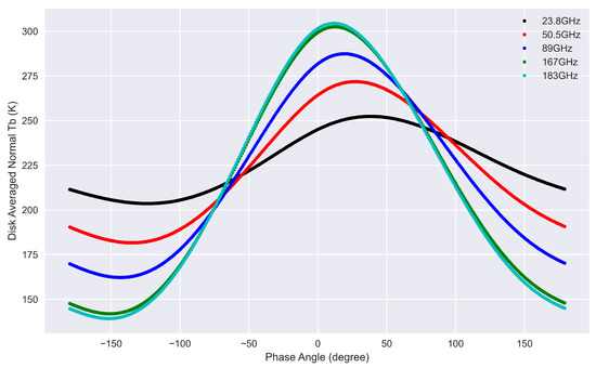
Figure 3.
The simulated lunar disk averaged black body Tb variation with Moon phase angle for frequency from 23.8 to 183 GHz.
4. Model Calibration with Satellite Observations
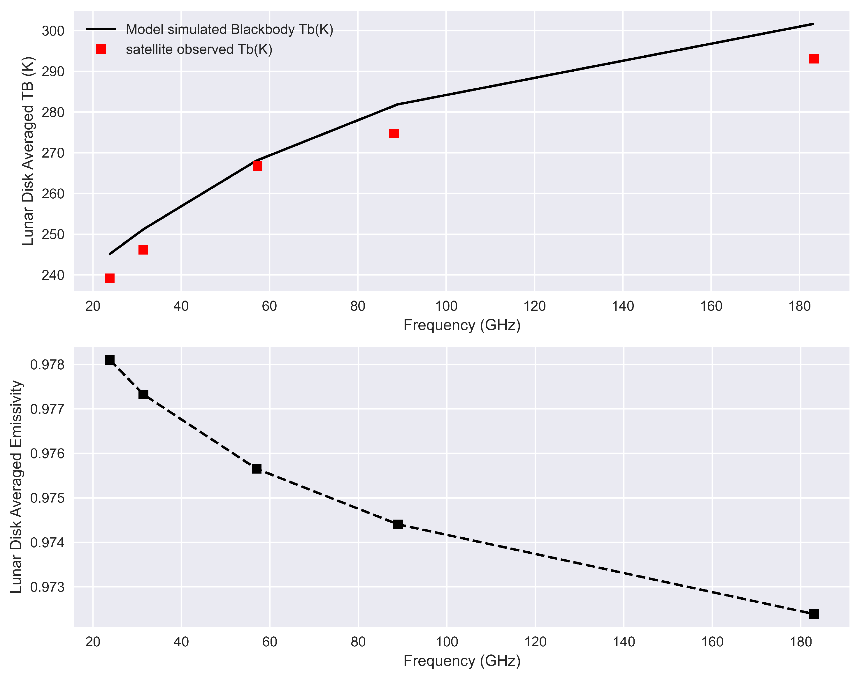
In our previous study, the disk-integrated lunar spectrum from 23 to 183 GHz of full-Moon was derived based on 2D lunar scan observations from the ATMS instrument onboard the NOAA-20 satellite. By taking the lunar disk-averaged s from ATMS as the reference truth, the Keihm model can be calibrated to the satellite observations. As shown in Figure 4, the trend of lunar simulated disk average spectrum of full moon shows great consistency with satellite observations. The magnitude of simulated is systematically warmer than satellite observations, which is reasonable considering the fact that the current model is only for “Black body” microwave emission of lunar surface and therefore will overestimate the effective lunar . It also should be noted that while the satellite observation is mix-polarized, which is Quasi-V for 23, 31 and 89 GHz, and Quasi-H polarization for 50, 167 and 183 GHz, there is no polarization dependence in the simulated “Black body” emission. It is also observed that the ratio between satellite observation and simulations decrease with increased frequency, which is caused by a frequency dependent feature of lunar surface microwave electrical properties. By comparing the satellite observed lunar spectrum with RTM simulated “black body” , the effective lunar surface emissivity in Equation (2) can be calculated as:
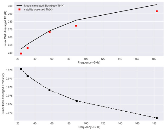
Figure 4.
The disk-integrated lunar brightness temperature spectrum (upper panel) and effective emissivity at full-Moon phase (lower panel).
For the simulated frequency spectrum, it can also be expressed as a function of detection frequency:
where a = −5.66 , b = −2.87 . f is the detection frequency in GHz. It shows that the disk-averaged lunar surface emissivity decreases with the increase of the detection frequencies, it changes from 0.978 at the 23.8 GHz, to 0.972 at the 183 GHz.
5. Model Performance Evaluation with the Satellite Observations
To evaluate the performance of the calibrated lunar RTM model in the studied frequency range, the satellite lunar observation samples from NOAA-18 AMSU-A were collected and calibrated, the retrieved lunar disk-integrated was then used to compare with the model simulations for frequency from 23 to 89 GHz. For frequency from 89 to 183 GHz, the lunar observation samples from AMSU-B and MHS instruments of different satellites were collected and used on this purpose.
5.1. AMSU-A
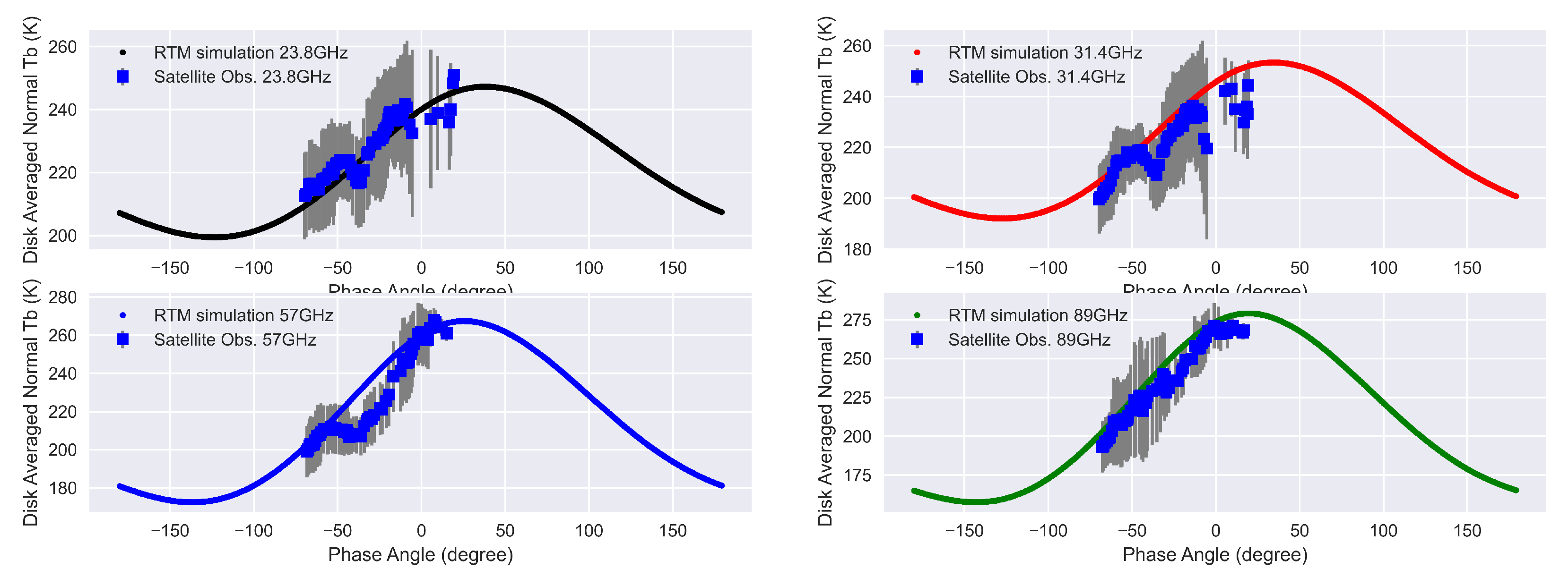
To evaluate the performance of the calibrated Keihm model, independent satellite lunar observation data sets were extracted from the 15 years of NOAA-18 AMSU-A space-view samples and compared with the model simulations. The AMSU-A is part of the Advanced Television InfraRed Operational Satellite (TIROS) Operational Vertical Sounder (ATOVS) sounding instrument suite. Together with the Microwave Humidity Sounder (MHS), it is the precursor of the ATMS onboard NOAA-20 and SNPP. During lunar intrusion incidents (LI), the lunar observation samples of AMSU-A can be derived from space-view observations by calculating the position of the Moon in the rotation-antenna coordinate system, taking into consideration the satellite attitude, earth rotation axis alignment, and instrument mounting matrix [1,2]. Since there is only one space-view sample available at each AMSU-A scan, searching for “clean” reference calibration counts is challenging because the calibration gain keeps changing during the LI process. Any error in reference cold-calibration counts will make the calibration results for LI samples inaccurate. Here, LI-free clean space views closest to the LI samples were taken as the reference at the starting and ending times of the LI. Then a double successive substitution method was applied to interpolate the reference cold-calibration counts between the start and end reference points, given that the variation of the instrument gain between two consecutive scans (8 s for AMSU-A) is minimal. After reference cold-calibration counts are determined, and together with the internal warm-calibration target, the LI samples can then be calibrated to effective lunar temperatures. The details of the calibration process for AMSU-A lunar observations can be found in [15]. To calculate lunar disk-integrated microwave s from effective lunar s, for each LI event, kept were only those LI samples collected when the Moon passed through the antenna beam center. Here, 15 years of NOAA-18 AMSU-A data from 2005 to 2019 were processed, from which lunar microwave s were derived at different lunar phase angles and compared with the model simulations.
As presented in Figure 5, the lunar disk-averaged Tbs for frequencies at 23.8 GHz, 31.4 GHz, 57 GHz and 89 GHz were selected to be compared between the model simulations and the satellite observations. The trend of phase angle dependent lunar disk average s match very well. The sudden dips are observed in the satellite observations at the phase angles between −50° to 0° , which are believed to be caused by the lack of good data samples in the satellite space view. The mean error and its standard deviation are calculated from the total of 97 samples for the four frequencies. As listed in Table 1, the mean errors and their standard deviations are less than 10 K for all frequencies under investigation. It should be noted that the mean errors are well within the uncertainties in the lunar disk-averaged s retrieved from AMSU-A observations, which is 15 K in 23.8 GHz, 16 K in 31.4 GHz, 13 K in 57 GHz, and 18 K in 89 GHz. For comparison, the difference between satellite observations and the model simulations with Fresnel surface emissivities are also listed in Table 2. It can be seen that by using the Fresnel emissivities, the simulated lunar microwave brightness temperature are largely underestimated.
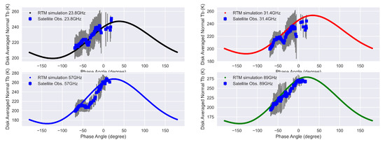
Figure 5.
Comparison of simulated and observed lunar disk averaged brightness temperature at different frequencies. Solid lines are the calibrated Keihm model simulations, the dots are the satellite observations, and the grey bar is the standard deviation of the satellite derived lunar-disk averaged .

Table 1.
The Mean and Std. of the difference between Satellite Observations and the Model Simulations.

Table 2.
The Mean and Std. of the TB difference between Satellite Observations with MHS and the Model Simulations.
5.2. AMSU-B and MHS
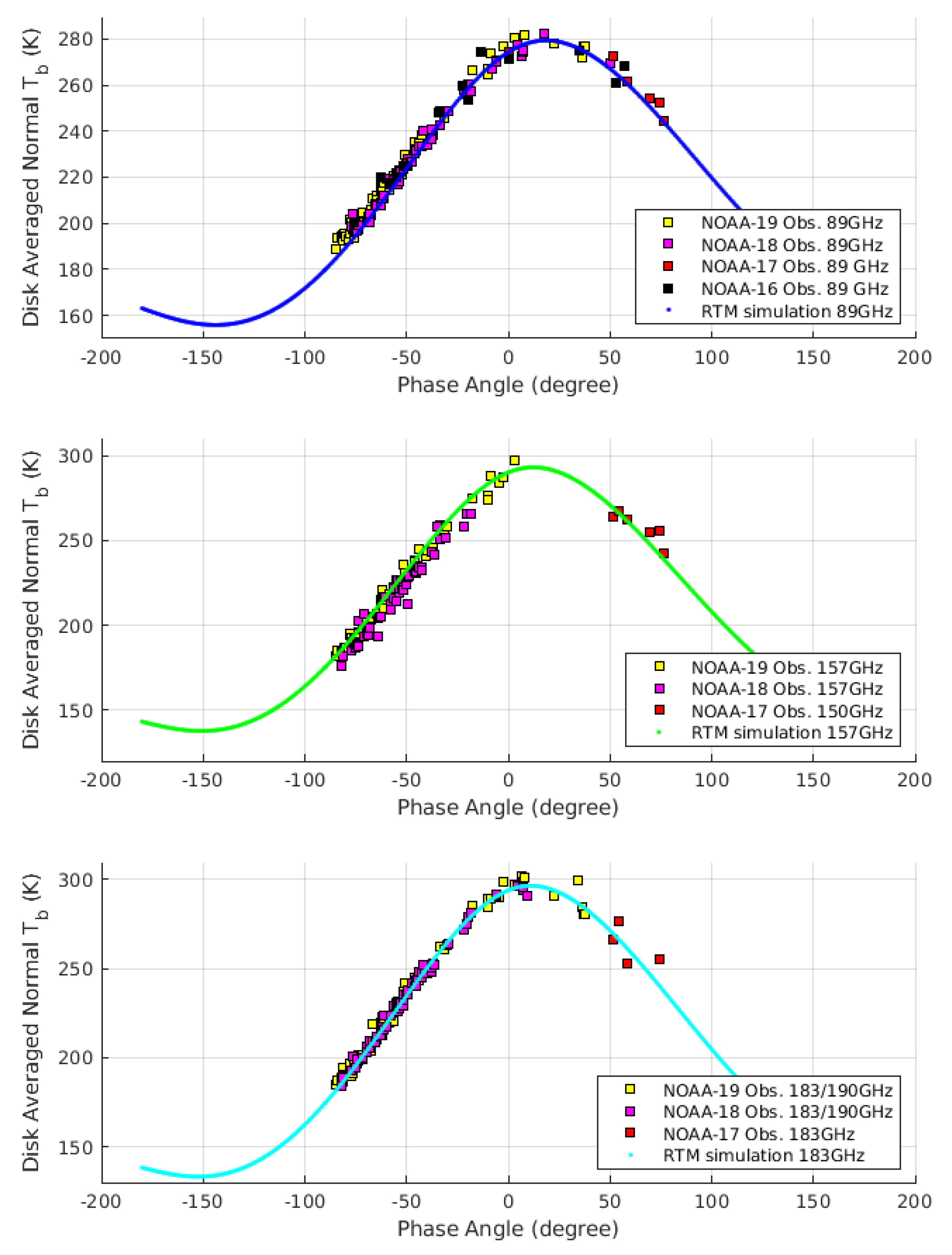
With the above mentioned AMSU-B and MHS it is possible to evaluate the performance of the calibrated Keihm model at 89 GHz and higher frequencies. They flew on the same satellites as AMSU-A, and MHS replaced AMSU-B on NOAA-18 and later satellites. The low noise in particular of MHS— is only 0.22 K for the channel at 89 GHz [16]—in combination with the small diameter of the field of view, which is nominally for both instruments, means that the flux density from the Moon can be measured with a signal-to-noise ratio of several hundred. In order to extend the validation of the model over a large range of phase angles, we include three, and at 89 GHz even four, satellites in our set of observations. As all NOAA satellites, except for the last one, NOAA-20, had considerable orbit drifts, all of these satellites combined observed at phase angles from first quarter to waning gibbous Moon. A drift of the orbit causes the equator crossing time to change slowly, and the equator crossing time determines the angular distance of the deep space view from the Sun, which for its part determines under what phase angle the Moon appears in the deep space view.
A major difference between AMSU-B/MHS and AMSU-A is that the former instruments take four space-view samples in every scan. This means that it is possible to determine the exact position of the Moon in the scan direction from the signal in each of the four different space-view samples. In particular one can identify those instances, where the Moon stood very close to the center of sample n: This is the case, when one gets similar counts from samples and . The calibration of the raw data was less error-prone than for AMSU-A, because the whole lunar intrusion lasts only about 2 min with AMSU-B and MHS. In consequence the variation of the instrument gain during the observation of the Moon is small. The reasons for the short duration of the Moon intrusion are the smaller field of view and the larger space viewing angle with MHS. The latter causes a faster angular movement of the space view in the sky as the spacecraft orbits the Earth—the space view would have no angular movement, if its viewing angle was zero, i.e., aligned with the orbital axis of the satellite. As MHS was operational for more than twelve years on NOAA-18 and -19, it produced hundreds of observations of the Moon, allowing us to place tight constraints on any model of the lunar radiance. In Figure 6 we present the lunar disk-averaged brightness temperatures for the frequencies of MHS, i.e., 89, 157, and 183/190 GHz. We took the average of the observations at 183 GHz (channels 3 and 4) and 190 GHz (channel 5) in order to improve the signal-to-noise ratio. It follows from our model that the lunar differs by less than 1 K between these two frequencies. AMSU-B has channels at 89, 150, and 183 GHz. As we have many more observations with MHS of the waxing than of the waning Moon, we have also included some observations with AMSU-B, even though this instrument has higher noise. The mean difference between observation and simulation is smaller than 3 K, see Table 2, with the only exception being channel 2 of MHS at 157 GHz, where the observations lie 5 K below the model predictions. It is possible that this discrepancy is due to an incorrect assumption of the diameter of the field of view (FoV). If the FoV of this channel was only 1% larger than the value we used in our calculations, this would bring the mean of to zero. In any case the mean errors and their standard deviations are less than 12K for all frequencies of MHS, and less than 6K if we consider NOAA-18 only. We did not analyse enough observations with AMSU-B for a meaningful statistical analysis. For comparison, the difference between the satellite observations and the model simulations with Fresnel surface emissivities, , are also listed in Table 2. It can be seen that by using the Fresnel surface emissivities, the RTM model largely under-estimate the microwave lunar brightness temperature.
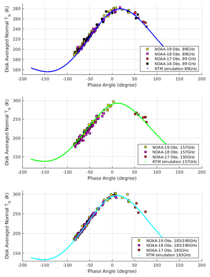
Figure 6.
Comparison of simulated and observed lunar disk averaged brightness temperature at frequencies of 89 GHz and higher. Solid lines are our model simulations, the dots are the satellite observations with AMSU-B and MHS. The error bars would be of similar size as the symbols and were therefore not plotted..
6. Conclusions and Discussions
A reliable lunar radiation brightness temperature data set in microwave band is important for microwave lunar calibration, and this can only be achieved by combining the RTM model simulation and the accurate satellite observations. Presented in this study is the calibration and improvement of the lunar microwave RTM model based on satellite observations. A multi-layer microwave emission model was firstly being used to simulate the radiation caused by electric loss in the lunar regolith, then the Moon surface emissivities were determined by comparing the model simulation with NOAA-20 ATMS lunar scan observations at the 180° Moon phase angle. The calibrated RTM model was then validated against the satellite lunar observations independently collected from AMSU-A and AMSU-B/MHS onboard NOAA-16, 17, 18, 19 and Metop-A,B,C satellites. A significant improvement in the accuracy of the RTM model was observed in the frequency range of 22 to 183 GHz. To assess the impacts of the errors in calculated Moon disk-averaged Tbs on the accuracy of microwave lunar calibration, an error model can be established based on our previous study in [12]. According to the Equation (5) in [12], When used as calibration target, the Ta of the Moon can be calculated from the equation below:
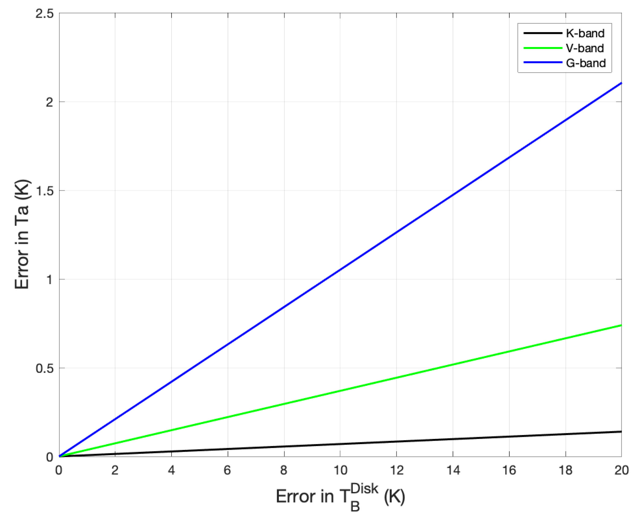
where and are the solid angle for Moon disk and the antenna in different frequencies. By using the solid angle values listed in Table 1 of [12], the impact of errors in on the accuracy of calculated antenna temperature, Ta, can be calculated from Equation (9). As shown in the Figure 7, the sensitivity of the error in Ta to the error in is frequency dependent: for high frequency band with smaller antenna solid angle, it is more sensitive to the accuracy of the simulated . For example, while a 10 K error in only causes 0.06 K error in Ta for K band, it becomes 0.95 K error for G band. Considering that in this work, the error in calibrated RTM model is generally less than 10 K, and the relatively larger error only observed for satellite observations with higher noise. Therefore we believe that when using the proposed model simulated Moon disk-averaged Tbs for microwave lunar calibration, without considering the error in antenna solid angle, the accuracy for the calculated lunar antenna temperature can be 0.06 K for K-band with 5.2° beam width, 0.4 K for V/W band with 2.2° beam width, and 1 K for G band with 1.1° beam width.
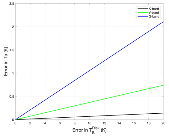
Figure 7.
Sensitivity of the errors in satellite observed antenna temperature of the Moon disk to the uncertainty in simulated Moon disk-averaged brightness temperature . Presented are the results for K, V, and G band.
Author Contributions
Conceptualization, methodology, software by H.Y.; Validation by M.B. and H.Y. All authors have read and agreed to the published version of the manuscript.
Funding
This study was supported by NOAA grant NA19NES4320002 (Cooperative Institute for Satellite Earth System Studies -CISESS) at the University of Maryland/ESSIC) and by Deutsche Forschungsgemeinschaft, project number 421761264 (MW-Luna-2). With this work we contribute to the Cluster of Excellence “CLICCS—Climate, Climatic Change, and Society” funded by the Deutsche Forschungsgemeinschaft DFG (EXC 2037, Project Number 390683824), and to the Center for Earth System Research and Sustainability (CEN) of Universität Hamburg.
Data Availability Statement
NOAA satellite data used in this paper can be found from the NOAA Class server: https://www.avl.class.noaa.gov/saa/products/catSearch, (accessed on 1 September 2022).
Acknowledgments
Many thanks to Stevphen J. Keihm for providing the great support in microwave lunar radiative transfer model. His knowledge of lunar RTM and the advises are indispensable for this study and are greatly appreciated.
Conflicts of Interest
The authors declare no conflict of interest.
References
- Yang, H.; Zhou, J.; Weng, F.; Sun, N.; Anderson, K.; Liu, Q.; Kim, E.J. Developing vicarious calibration for microwave sounding instruments by using lunar radiation. IEEE Geosci. Remote Sens. 2018, 56, 6723–6733. [Google Scholar] [CrossRef]
- Burgdorf, M.; Buehler, S.A.; Lang, T.; Michel, S.; Hans, I. The Moon as a photometric calibration standard for microwave sensors. Atmos. Meas. Tech. 2016, 9, 3467–3475. [Google Scholar] [CrossRef]
- Hu, G.; Zheng, Y.; Xu, A.; Tang, Z. Microwave Brightness Temperature of the Moon: The Possibility of Setting a Calibration Source of the Lunar Surface. IEEE Geosci. Remote Sens. Lett. 2016, 13, 182–186. [Google Scholar] [CrossRef]
- Williams, J.-P.; Paige, D.A.; Greenhagen, B.T.; Sefton-Nash, E. The global surface temperatures of the Moon as measured by the Diviner Lunar Radiometer Experiment. ICARUS 2016, 283, 300–325. [Google Scholar] [CrossRef]
- Hayne, P.O.; Bandfield, J.L.; Siegler, M.A.; Vasavada, A.R.; Ghent, R.R.; Williams, J.-P.; Paige, D.A. Global regolith thermophysical properties of the Moon from the Diviner Lunar Radiometer Experiment. J. Geophys. Res. Planets 2017, 122, 2371–2400. [Google Scholar] [CrossRef]
- Krotikov, V.D.; Troitskii, V.S. Radio Emission And Nature of The Moon. Soviet Phys. Uspekhi 1964, 6, 841–871. [Google Scholar] [CrossRef]
- Keihm, S.J.; Cutts, J.A. Vertical-Structure Effects on Planetary Microwave Brightness Temperature Measurements: Applications to the Lunar Regolith. ICARUS 1981, 48, 201–229. [Google Scholar] [CrossRef]
- Keihm, S.J. Effects of Subsurface Volume Scattering on the Lunar Microwave Brightness Temperature Spectrum. ICARUS 1982, 52, 570–584. [Google Scholar] [CrossRef]
- Keihm, S.J. Interpretation of the Lunar Microwave Brightness Temperature Spectrum: Feasibility of Orbital Heat Flow Mapping. ICARUS 1984, 60, 568–589. [Google Scholar] [CrossRef]
- Liu, N.; Jin, Y. Average Brightness Temperature of Lunar Surface for Calibration of Multichannel Millimeter-Wave Radiometer From 89 to 183 GHz and Data Validation. IEEE Trans. Geosci. Remote. Sens. 2021, 59, 1345–1354. [Google Scholar] [CrossRef]
- Hu, G.-P.; Chan, K.L.; Zheng, Y.-C.; Tsang, K.T.; Xu, A.-A. Comparison and evaluation of the Chang’E microwave radiometer data based on theoretical computation of brightness temperatures at the Apollo 15 and 17 sites. ICARUS 2017, 294, 72–80. [Google Scholar] [CrossRef]
- Yang, H.; Zhou, J.; Sun, N.; Liu, Q.; Leslie, R.; Anderson, K.; Kim, E.; Lyu, C.-H.; Smith, C.; McCormick, L. 2-D Lunar Microwave Radiance Observations From the NOAA-20 ATMS. IEEE Geosci. Remote Sens. Lett. 2021, 18, 2021–2024. [Google Scholar] [CrossRef]
- Piddington, H.; Minnett, H.C. Microwave thermal radiation from the Moon. Aust. J. Sci. Res. Ser. A 1949, 2, 63–77. [Google Scholar] [CrossRef]
- Jaeger, J.C. The Surface Temperature of the Moon; Provided by the NASA Astrophysics Data System; CSIRO: Canberra, Australia, 1952. [Google Scholar]
- Yang, H.; Burgdorf, M. A Study of Lunar Microwave Radiation Based on Satellite Observations. Remote Sens. 2020, 12, 1129. [Google Scholar] [CrossRef]
- WMO OSCAR. Space-Based Capabilities-Instruments. 2016. Available online: http://www.wmo-sat.info/oscar/instruments (accessed on 29 August 2022).
Publisher’s Note: MDPI stays neutral with regard to jurisdictional claims in published maps and institutional affiliations. |
© 2022 by the authors. Licensee MDPI, Basel, Switzerland. This article is an open access article distributed under the terms and conditions of the Creative Commons Attribution (CC BY) license (https://creativecommons.org/licenses/by/4.0/).

