1. Introduction
The joint application of low-cost inertial sensors, miniature global navigation satellite system (GNSS) receivers, and barometers has been one of the research hotspots in the field of navigation in the past decade [
1,
2,
3]. Accurate and continuous pedestrian location information is widely used in professional applications such as armed police duty, field walking, pipeline maintenance, etc. The satellite navigation system can provide users with good location services in an open outdoor environment [
4,
5]. However, the system cannot work well in some scenarios where GNSS signals are unavailable [
6,
7]. Other information sources such as wireless local area networks (WLAN) [
8], ultra-wideband (UWB) [
9], radio frequency identification (RFID) [
10], etc., can directly provide location information. However, there is a problem of signal occlusion in indoor scenarios. Generally, WiFi positioning and UWB positioning require extensive installation of signal receiving devices during the actual operation. Whether fingerprint positioning or trilateral measurement, WiFi positioning cannot be separated from offline surveying and mapping, limiting its application mode. Cameras [
11] and radar [
12] can improve the robustness of the system, however, these sensors only work effectively when there are enough features in the environment, which limits their application.
Some solutions such as multi-source information fusion have been proposed around the demand for continuous and reliable pedestrian navigation. Zhu et al. proposed a novel pedestrian navigation system (PNS) integrating RTK/Pseudolite/LAHDE/IMU, which uses manmade landmarks deployed at the entrance of the corridor to determine whether pedestrians are in an indoor corridor. If pedestrians do not follow a route with landmarks, the error will accumulate quickly [
13]. Xin et al. presented a joint positioning scheme combining Bluetooth and inertial navigation systems, which provides meter-level positioning services without additional facilities [
14]. Cavallo et al. introduced a solution which uses global position system (GPS) and Bluetooth to assist pedestrian trajectory calculation. This solution can continuously provide reliable positioning results for pedestrians in indoor or outdoor environments [
15]. In [
16], Polak et al. extended the power level measurement by using multiple anchors and multiple radio channels and focuses on the employing of machine learning methods to improve localization accuracy in an indoor environment under different conditions. In [
17], Sun et al. integrated ultra-wideband technology and PDR to solve the problem of accumulated errors in inertial navigation systems. Compared with traditional methods, the positioning accuracy has been effectively improved.
As pedestrian movement patterns are complex, providing high-precision positioning in a complex environment is difficult by using a single navigation technology. With the continuous development of micro electro mechanical system (MEMS) technology, many sensor modules can be highly integrated into a small, low-power module, which provides natural advantages for public pedestrian navigation [
18]. Magnetometer-assisted pedestrian navigation has long been widely studied [
19,
20]. To make magnetometer information play an active role in the system, the soft and hard magnetic effects must be calibrated, and the geomagnetic interference must be modeled and compensated [
21,
22]. Although the pedestrian navigation system based on inertial measurement units (IMU) can continuously provide positioning information, the positioning accuracy will quickly accumulate over time [
23]. Mining pedestrian motion constraint information is of great significance for improving the performance of low-cost sensors. Pedestrians have natural zero-velocity information constraints during walking. Therefore, a zero-velocity update (ZUPT) algorithm can be widely used to suppress error accumulation [
24]. In the zero-velocity phase of a gait cycle, the ZUPT algorithm combined with the extended Kalman filter (EKF) can effectively improve the positioning accuracy [
25,
26].
For this reason, various gait detection schemes have been proposed [
27,
28,
29,
30,
31,
32,
33]. Skog et al. used the output of IMU to offer a zero-velocity detection method based on a general likelihood ratio test (GLRT) [
27]. Experiments show that this method achieves good results at a slow walking speed. Wang et al. proposed an adaptive stance-phase detection method based on inertial sensor, which deals with the measurement fluctuations in swing and stance phases differently and performs well in the presence of measurement fluctuations [
28]. Liu et al. adjusted the threshold of zero-velocity detection dynamically according to the output of the accelerometer [
29]. In [
30], Wang et al. designed an algorithm to adjust the length of the window without changing the threshold. These methods do not clearly explain the connection with the existing zero-velocity detection methods based on maximum likelihood detection. In recent years, many researchers have proposed some detection methods based on artificial intelligence (hidden Markov model (HMM) [
31], support vector machine (SVM) [
32], long short term memory (LSTM) [
33]) without threshold of zero-velocity detection in the pedestrian navigation system. Compared with traditional zero-velocity detection methods, these methods do not need to set specific thresholds. Although these methods require a lot of data to train the model and have a high computational cost, they are more robust than the traditional methods.
Although the traditional zero-velocity detection method can detect the zero-velocity state of pedestrians, it is hard to set the threshold of zero-velocity detection appropriately. The GNSS/SINS integrated navigation system can provide reliable positioning results in outdoor open environment, but it is not available in an indoor environment as the GNSS signal is interrupted. In this article, a robust single-frequency GNSS/PDR pedestrian navigation system is proposed. The error state Kalman filter is used to fuse GNSS positioning information, zero-velocity state, barometer elevation, and other information. The zero-velocity detector based on GRU can accurately detect the motion state of pedestrians. The adaptive robustness algorithm and lever arm model are used to make the system more robust. Experiments show that the proposed algorithm can obtain reliable positioning results in complex environments.
The rest of this article is arranged as follows. The second section presents the GNSS/PDR integration scheme architecture. In the third section, the main algorithms of the scheme are introduced, including improved carrier phase smoothing pseudo-range GNSS single-point positioning algorithm, GRU-based zero-velocity gait detection, and adaptive fusion algorithm of GNSS and PDR. The fourth section introduces the experiment results and analysis. The conclusion of this paper is given in the fifth section.
2. GNSS/PDR Integration Scheme Architecture
A robust integration scheme for single-frequency single-antenna GNSS/PDR in complex environments is proposed. It is designed to provide reliable, continuous, and accurate positioning results for low-cost mass pedestrian positioning in complex environments. Algorithmically, this integration scheme uses the error state EKF as the algorithm framework, considering the gait characteristics of pedestrian walking, and fusing GNSS position, barometer height, and other information. From the point of view of program realization, the high efficiency of calculation, the scalability of code, and modular programming are evaluated. The code structure is clear, which is convenient for developers to maintain, update, and collaborate. The scheme is mainly composed of the following five parts:
Single-frequency data quality analysis, preprocessing, etc.
Improve carrier phase smoothing GNSS single point positioning.
GRU-based zero-velocity detector.
Adaptive GNSS/PDR fusion positioning.
Error analysis and visualization of positioning results.
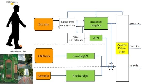
The data fusion strategy flowchart is shown in
Figure 1. Because of the unpredictability of pedestrian motion patterns and low sensor accuracy, the foot-mounted pedestrian navigation system is used as the basis, and the error state Kalman filter is used as the data fusion framework to deeply explore the performance of MEMS sensors. Motion constraint information is used to improve the positioning capability of the system.
Figure 1 shows the single-frequency GNSS/PDR positioning algorithm. It mainly includes four parts: (1) GNSS positioning algorithm, (2) PDR algorithm, (3) GNSS/PDR positioning algorithm, (4) GRU-based gait detection algorithm.
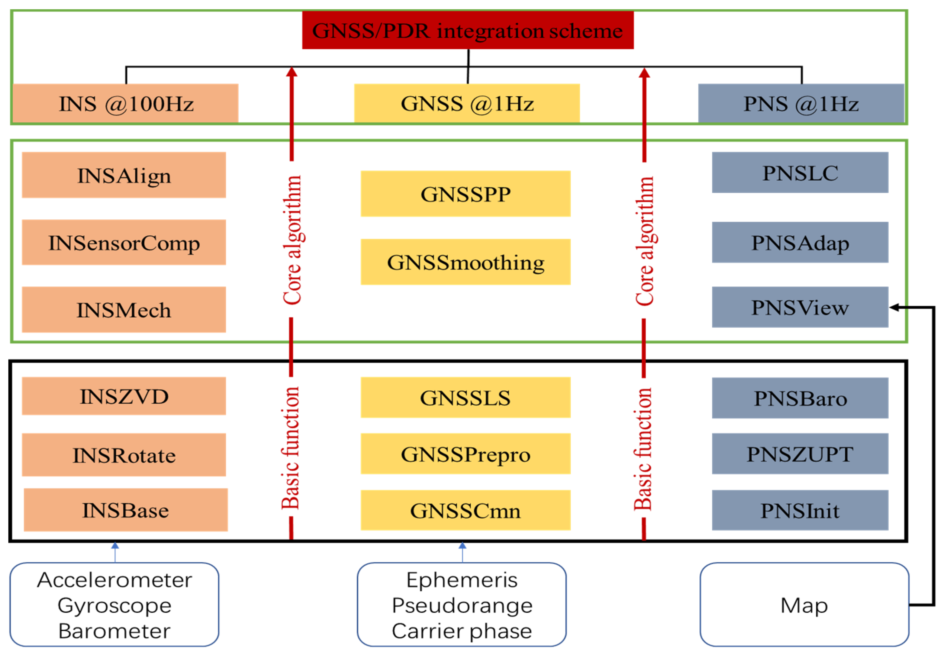
The overall architecture of the scheme is shown in
Figure 2. The three sub-modules included are named INS module, GNSS module, and PNS module. INS module implements algorithms related to INS, GNSS module implements algorithms related to GNSS, and PNS module implements integrated navigation, self-adaptation, and result in display. Each sub-module contains its basic function and main algorithm.
3. Fusion Method of GNSS and ZUPT-Aided PDR
The algorithm flow chart is shown in
Figure 1. This section shows the GNSS data preprocessing strategy, single-frequency single-antenna positioning algorithm, GRU-based zero-velocity detection, and GNSS/PDR integrated navigation algorithm.
3.1. GNSS Data Preprocessing Strategy and Single-Frequency GNSS Positioning Algorithm
Evaluating the data quality of observations from low-cost GNSS modules can provide a basis for the preprocessing of observations. The satellite visibility, carrier-to-noise ratio (), and pseudo-range noise are quantitatively evaluated and analyzed based on measured data. The number of visible satellites will directly affect the number of redundant observations in the data preprocessing. The is an essential indicator of the quality of the received observations. The GNSS/PDR integration scheme uses a variety of strategies to preprocess GNSS data, including detecting cycle slips and removing it, and for the problem that observations are prone to gross errors when the observations are at a low signal-to-noise ratio. Eliminate satellites below the threshold to avoid introducing abnormal observation information.
Hatch filtering is a standard processing method of traditional single-frequency carrier smoothing pseudo-range [
34]. The traditional single-frequency hatch filter algorithm is prone to the problems of divergence of smoothing results and decreased accuracy due to the influence of ionospheric delay changes. In [
35], Chebir et al. proposed a method based on applying specific transformations to the GNSS signals received in unfavorable environment, which can effectively receive and process GNSS signals in unfavorable environment. In [
36], Park used a moving window algorithm to improve the original single-frequency smoothing pseudo-range algorithm. There are two forms of single-frequency smoothing, and the corresponding smoothing between epochs can be defined as:
where
and
are the distances of the observed pseudo-range and carrier phase, respectively, and
is the length of the filter, which is determined according to the smoothing time
and the observation sampling
.
is the difference operator.
3.2. GRU-Based Zero-Velocity Detection
Recurrent neural network (RNN) is now widely used in time series-based forecasting tasks (pedestrian trajectory prediction [
37], vehicle trajectory prediction [
38], etc.). GRU is a special RNN with the ability to learn long-term dependency.
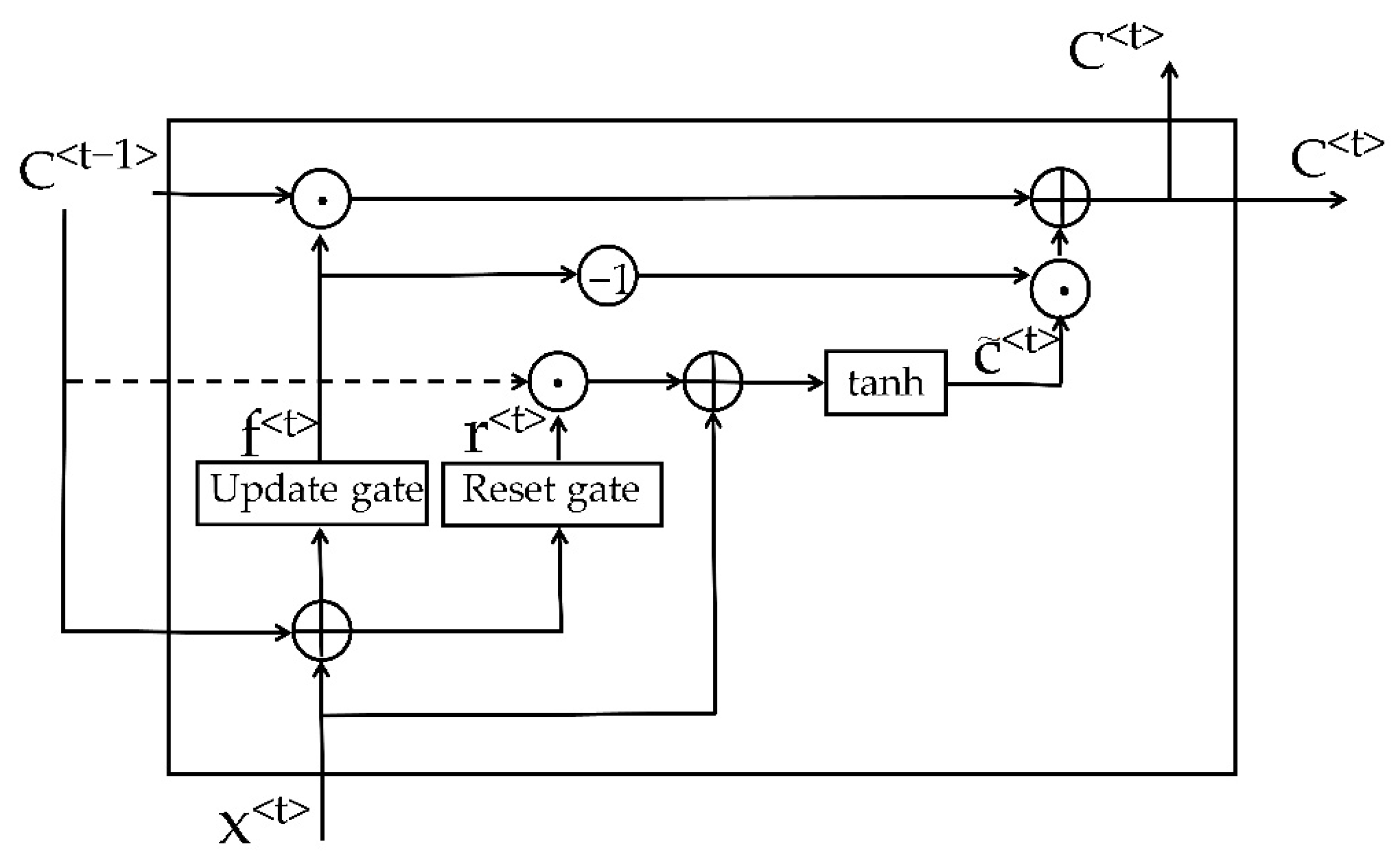
The structure of the GRU is shown in
Figure 3, which is composed of an update gate (
) and a reset gate (
). The larger the value of the update gate, the more the state information of the previous moment is brought in. The reset gate controls how much information is conveyed to the current candidate set (
). The smaller the reset gate is, the less information is passed to the previous state. The detailed update formula is as follows:
where
represents the relative position of the objects before and after multiplication.
represents the sigmoid activation of the following objects.
represents the activation value of the previous time step.
correspond to the weight matrix of each gate respectively.
,
,
are the bias vectors of reset gate, update gate, and hidden unit respectively.
GRU-based zero-velocity detectors need to collect IMU data from different objects to train the model. Currently, there is no standard method to generate labels. Some existing techniques (manual, pressure sensor, high-precision sports state capture system) are proposed to produce reliable zero-velocity information. In this paper, the results of RTK/INS combination are used as reference trajectories, adjust the threshold of the GLRT detector to produce the smallest RMSE, and use the zero-velocity state by the GLRT detector with an optimal threshold as a label.
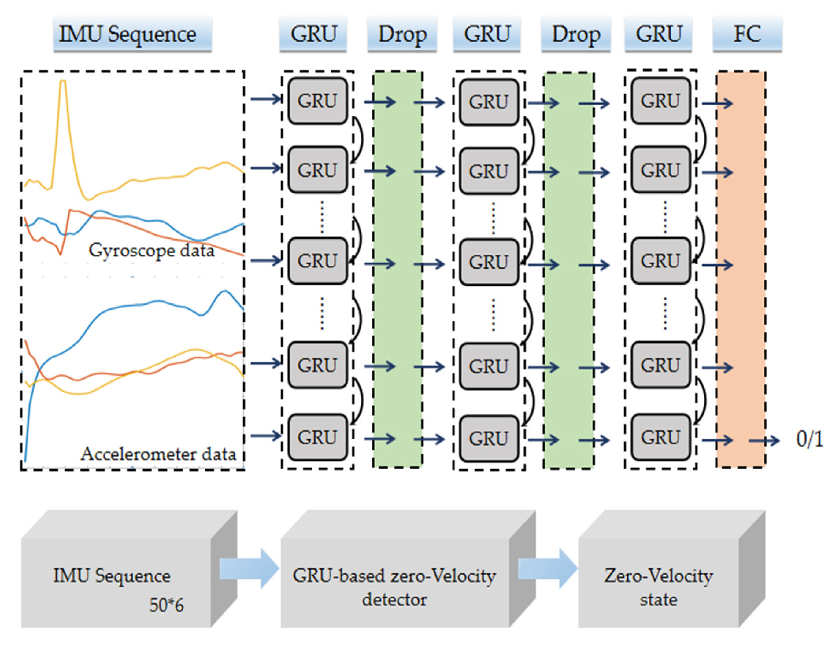
The structure of the zero-velocity detector is shown in
Figure 4, which is mainly composed of three GRU layers, two drop layers, and one fully connected layer (FC). Each layer of GRU has 100 neurons. To avoid overfitting, the drop layer is set to 0.2. The FC layer uses a sigmoid function as the activation function to map the model output to within (0, 1). It is assumed that current state is zero-velocity when the model output is greater than 0.8, otherwise, current state is non-zero-velocity. During the training process, 50 consecutive IMU data (specific force, angular velocity) constitute one sample, and a data set consisting of 300,000 samples is used to train this model. Each sample has an individual label which represents the zero-velocity state corresponding to the last time step. The Adam optimizer [
39] is used to optimize the model with 100 iterations. The loss function of the model is defined as follows:
where
represents the total number of training samples and
represents the label output of the
i-th sample.
3.3. Robust EKF Design for GNSS/PDR Integration
The error state EKF is used as the data fusion framework. The 15-dimensional error state vector is summarized as follows:
where
,
,
,
,
are all three-dimensional vectors and denote position, velocity, attitude, gyroscope bias, and accelerometer bias. The discrete-time error model of INS can be defined in matrix form as:
where
is the state transition matrix,
is process noise-driven matrix, and
is process noise, which is assumed to be Gaussian white noise with zero mean; the state transition and noise gain matrices can be written as:
where
represents the skew-symmetric matrix of a vector.
and
denote
identity matrix and zero matrices respectively. The bias errors of gyros and accelerometers can be expressed as first-order Gauss–Markov processes with the correlation time
,
.
When the observations (including the GNSS positioning results, the relative height difference of the barometer, and the zero-velocity information) are available, the measurement equation is constructed:
GNSS positioning is the main factor that determines the absolute positioning accuracy of the system and suppresses the error of the inertial sensor. At the same time, the lever arm error cannot be ignored, and the position observation equation is:
Use the barometer elevation change as the observation equation to update the elevation:
where
and
is the barometer elevation of the current epoch and the previous epoch, respectively.
and
is the elevation of the INS recursive of the current epoch and the previous epoch, respectively.
ZUPT is an effective means to control the accumulation of velocity errors. When the GRU recurrent neural network is used to detect that it is in a static state, the zero-velocity observation model is constructed:
3.4. Lever Correction
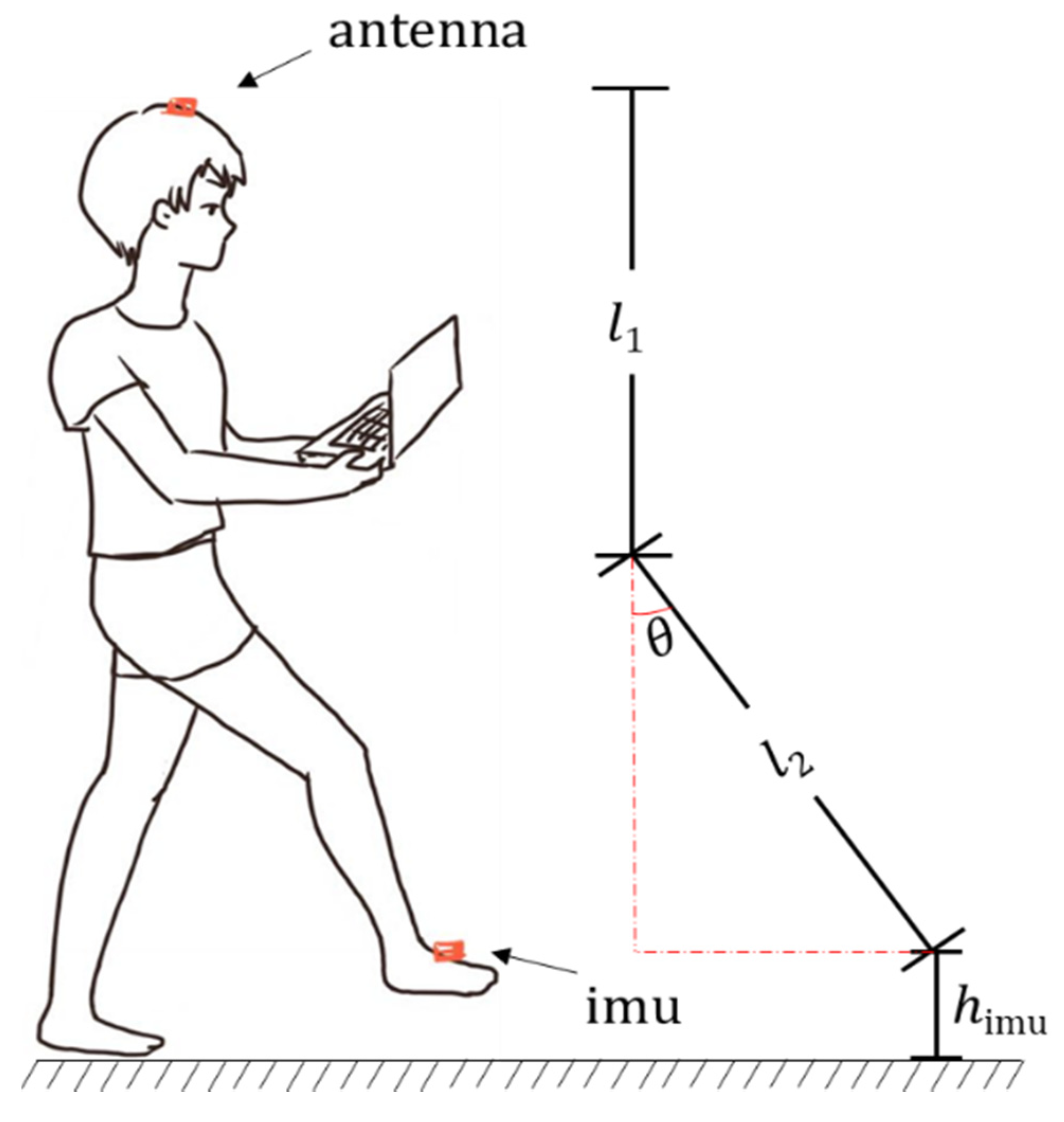
When carrying out the walking experiment, the IMU is fixed on the surface of the shoe, and the GNSS receiver antenna is set on the top of the head. The lever arm is constantly changing and cannot be ignored. It is not recommended to put the lever arm in the state vector as a parameter to be estimated, which not only increases the complexity of the calculation but also there is no way to evaluate whether the estimated value of the lever arm is correct. In the zero-velocity interval, the distance between the GNSS antenna and the IMU measurement center in the horizontal direction is much lower than the position error of GNSS single-point positioning result. The lever length in the vertical direction is equal to the height of the human subject. In the non-zero-velocity interval, it is modeled as a pendulum, as shown in
Figure 5. A lever arm is expressed as:
In the above
Figure 5,
represents the height from the top of the head to the waist,
is the length of the legs, which can be accurately known, and
is an unknown parameter, which can be obtained by solving the essential trigonometric function.
The error caused by the inaccurate lever arm modeling can be equivalent to the GNSS single-point positioning error, which can be effectively compensated by an adaptive filter.
3.5. Adaptive Kalman Filter
The GNSS outliers appear in the harsh environment due to the poor GNSS observation quality. However, the standard Kalman filter cannot solve this problem, which increases the positioning error of the GNSS/INS integrated system. Innovation-based adaptive estimation (IAE) filter is a popular filter to reduce the influence of outliers, which is adopted in this paper.
By calculating the average value of the covariance of the innovation vector of the previous N epochs, the estimate of the covariance of the innovation vector at current epoch and the estimation of the observation vector covariance matrix can be obtained:
where
denotes the covariance matrix of the state one-step prediction vector, and
denotes the innovation vector. This calculates the ratio of the trace of
to the trace of preset observation vector covariance matrix
. When the position result of GNSS is an outlier, this ratio will be greater than 1. The greater one between this ratio and one is taken as the adaptive factor:
The adaptive factor is used to expand the covariance matrix of the observation vector at the current epoch, which reduces the influence of GNSS outliers and increases the position accuracy of the GNSS/INS integrated system.
The paper studies the single-frequency single-system single-antenna pseudo-range single-point positioning assisted foot-mounted micro-inertial pedestrian navigation method. When carrying out the walking experiment, the MTi-G-710 is fixed on the shoe surface, the GNSS antenna is fixed on the top of the head, and the collected data is used to test the accuracy of carrier phase smoothing pseudo-range SPP positioning and the effect of SPP/SINS combination.
4. Results
MTi-G-710 produced by the Dutch company Xsens is selected as the experimental device, which integrates a three-axis gyroscope, a three-axis accelerometer, and a barometer. The performance parameters of the gyroscope and accelerometer are shown in
Table 1. The experimental GNSS module is the mosaic-X5 produced by Septentrio, Belgium, which is used to track all visible supporting satellites at the same time. The sampling rate of the IMU was set to 100. The data of the experiment is available for download here:
https://github.com/laotouyu123/data_set.git, accessed on 6 November 2021.
4.1. GRU-Based Zero-Velocity Detection Algorithm Performance Verification
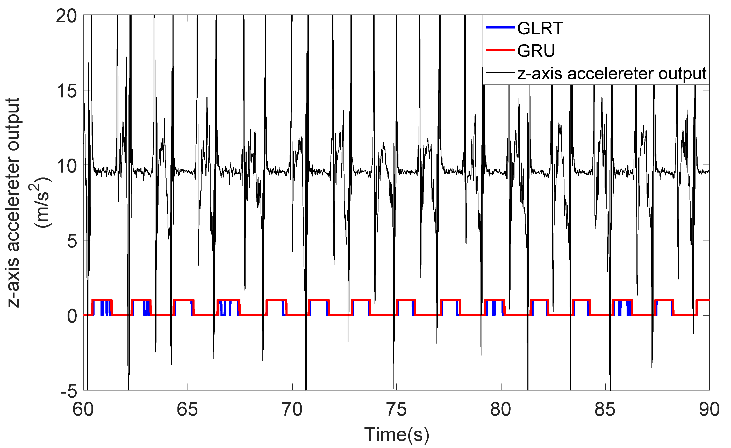
In order to verify the performance and generalization ability of the GRU-based zero-velocity detection method, ten experimenters carried out walking experiments on the same path at three walking speeds: slow, normal, and fast. The zero-velocity detection result of one of the experimenters is shown in
Figure 6.
As shown in
Figure 6, the GLRT method can effectively detect the zero-velocity most of the time. However, some incorrect zero-velocity results are detected by GLRT when the feet of the experimenter are moving, which will decrease the positioning precision of the PDR algorithm. The GRU method can detect the zero-velocity correctly all the time as the red curve shows in
Figure 6, which guarantees the availability of zero-velocity information.
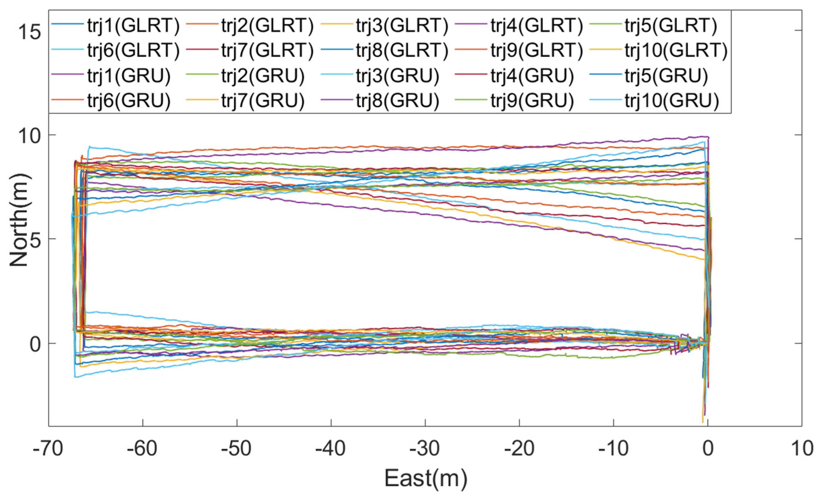
In order to verify the performance of the GRU-based zero-velocity detection method, a close-loop experiment is carried out, in which an experimenter walked 10 times along a rectangular trajectory. The trajectories obtained by two zero-velocity detect methods are shown in
Figure 7. It can be seen from
Figure 7 that the GLRT method obtained larger position error in the end point because of the incorrect zero-velocity information.
The closed-loop errors of all trajectories obtained by the GLRT method and the GRU method are listed in
Table 2. The minimum average closed-loop position error of the traditional GLRT zero-velocity detection method is 1.42 m, while the average closed-loop position error of the proposed method is 0.89 m, which means the proposed method performs better than the traditional algorithm.
4.2. The Proposed Algorithm Performance Verification under Open Environment
To verify the proposed algorithm performance under open environment, a data set (249 s in total) was collected under an open environment at Youyi Square, Faculty of Informatics, Wuhan University, Wuhan. The experimenter walks along the edge of Youyi Square during the experiment.
In the Kalman filter algorithm for pedestrian positioning, the relevant parameters are set as follows: initial speed error is , the initial position error is , the initial value of acceleration offset is , the initial value of gyroscope offset is , accelerometer noise is , gyro noise is , accelerometer bias driving noise , gyroscope bias driving noise .
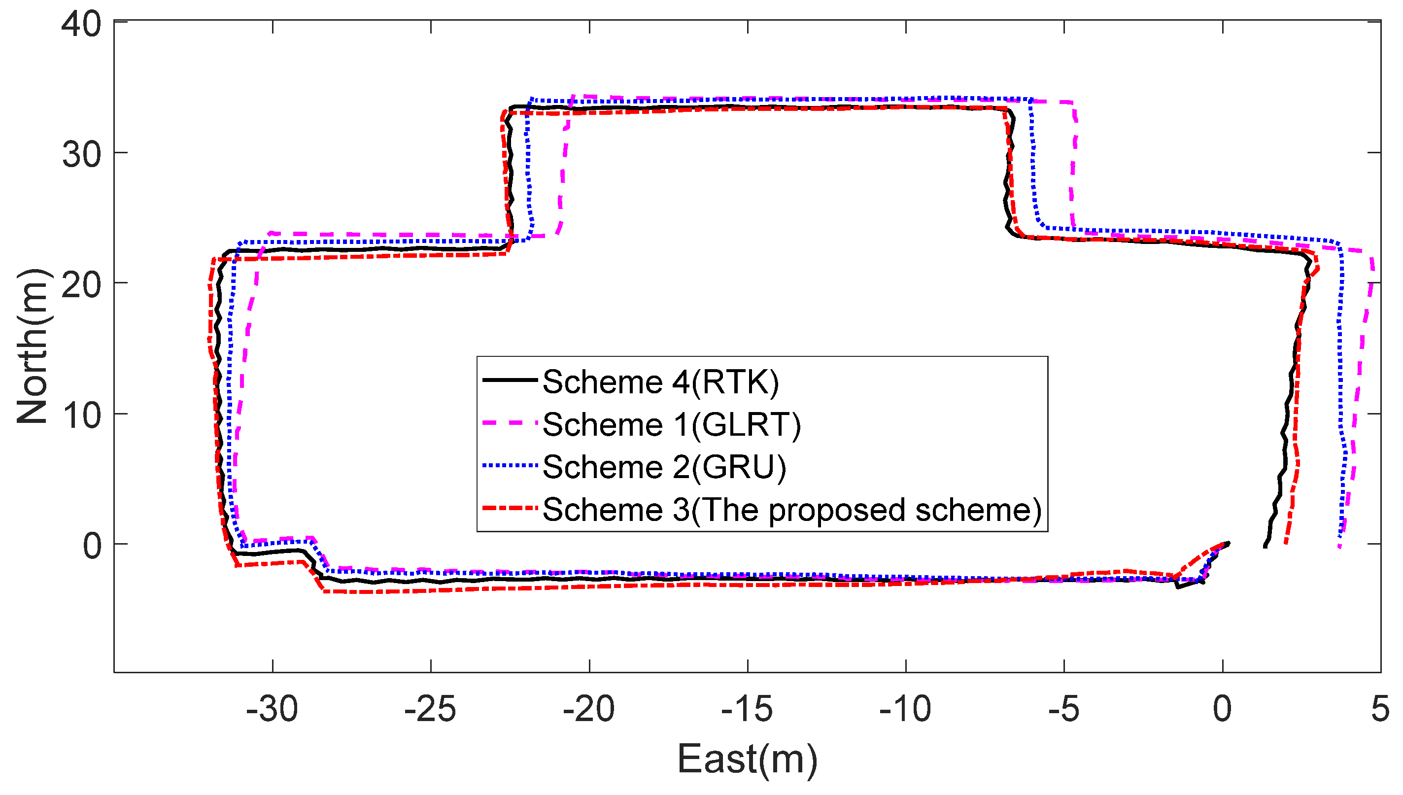
Compare the positioning result of the following four schemes: Scheme 1, use the GLRT method to detect the zero-velocity interval; Scheme 2, use the GRU method to detect the zero-velocity interval; Scheme 3, the proposed algorithm; Scheme 4, RTK. The trajectories of these schemes are shown in
Figure 8.
Under the open environment, RTK’s positioning error is small, so the RTK position result of Scheme 4 can be used as a reference truth value. The statistical results of three schemes are shown in
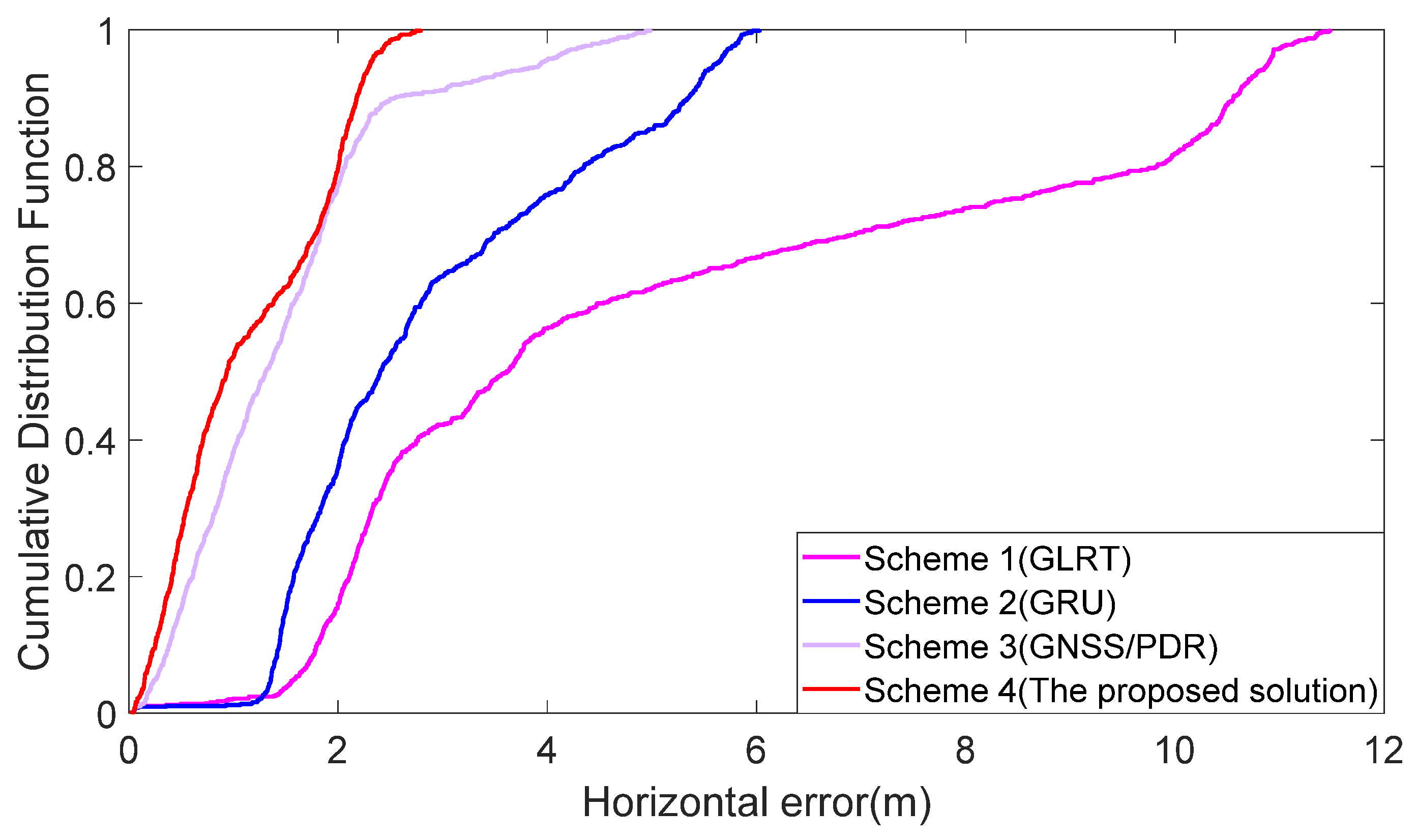
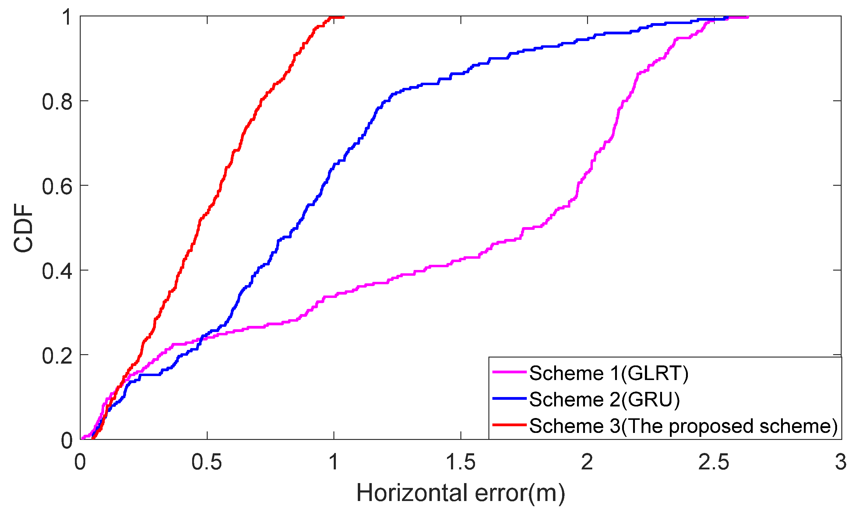
Table 3. It can be seen that the RMSE and maximum errors of Scheme 3 are more minor than those of the other two methods. The RMSE of these three schemes are 1.643 m, 1.042 m, and 0.543 m respectively. The maximum errors of the three schemes are 2.631 m, 2.54 m, and 1.03 m respectively. Compared with Schemes 1 and 2, RMSE of the proposed scheme are decreased by 67% and 48% respectively. In terms of maximum errors, compared with other two schemes, the maximum errors of the proposed scheme are decreased by 61% and 59% respectively. In order to more clearly reflect the performance of the proposed scheme, the Cumulative Distribution Function (CDF) of the horizontal error is shown in
Figure 9. It can be seen from
Figure 9 that 99% of the horizontal error of the proposed scheme is smaller than 1 m, while that of the other two schemes is 33% and 63%.
4.3. The Proposed Algorithm Performance Verification under Complex Environment
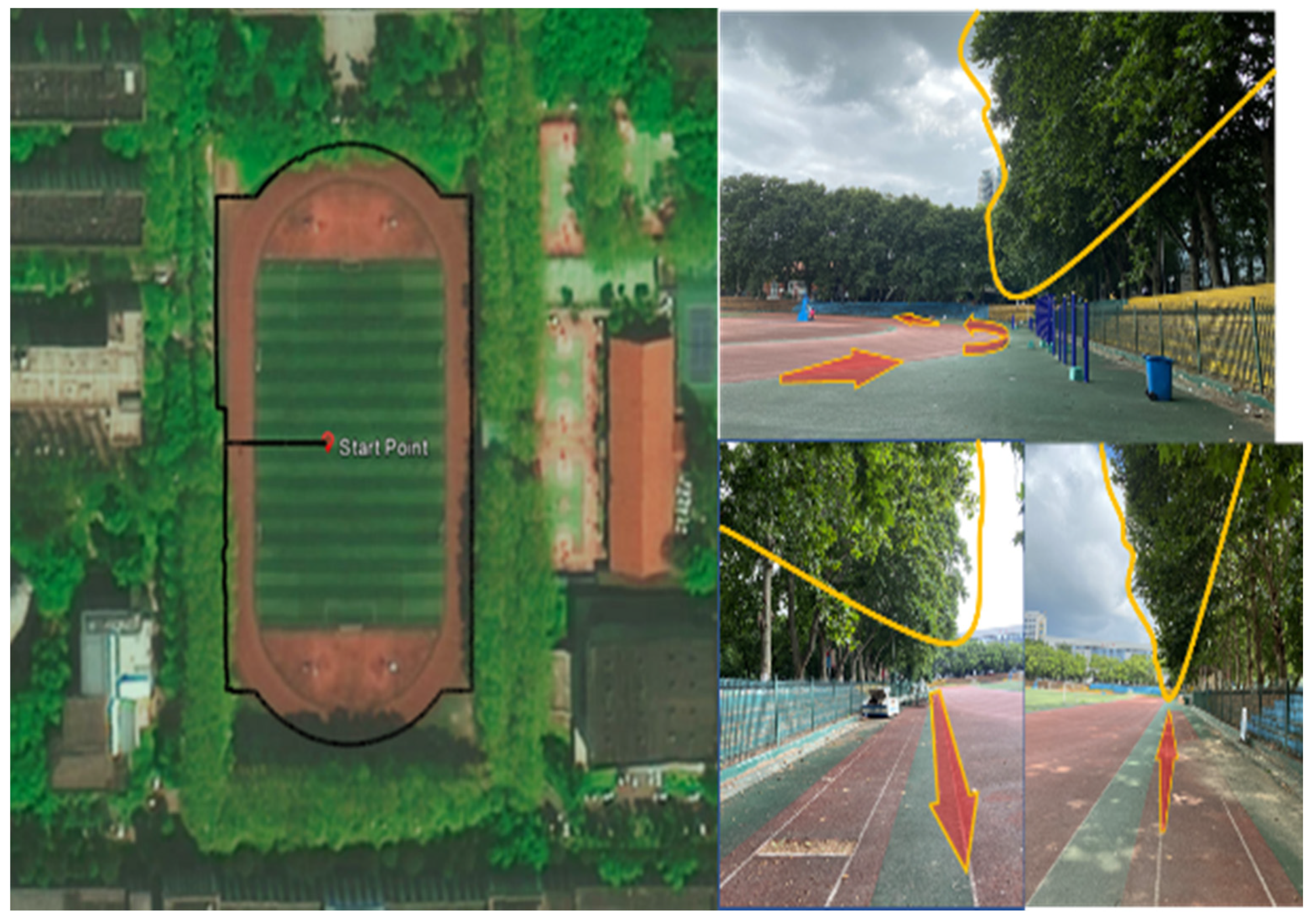
To verify the proposed algorithm performance under complex environment, a data set was collected in the playground of the Faculty of Information Science of Wuhan University, Wuhan. The experimenter walked along the outermost periphery of the playground. There are many interferences in the trajectory, including trees and houses. The experiment environment is shown in
Figure 10.
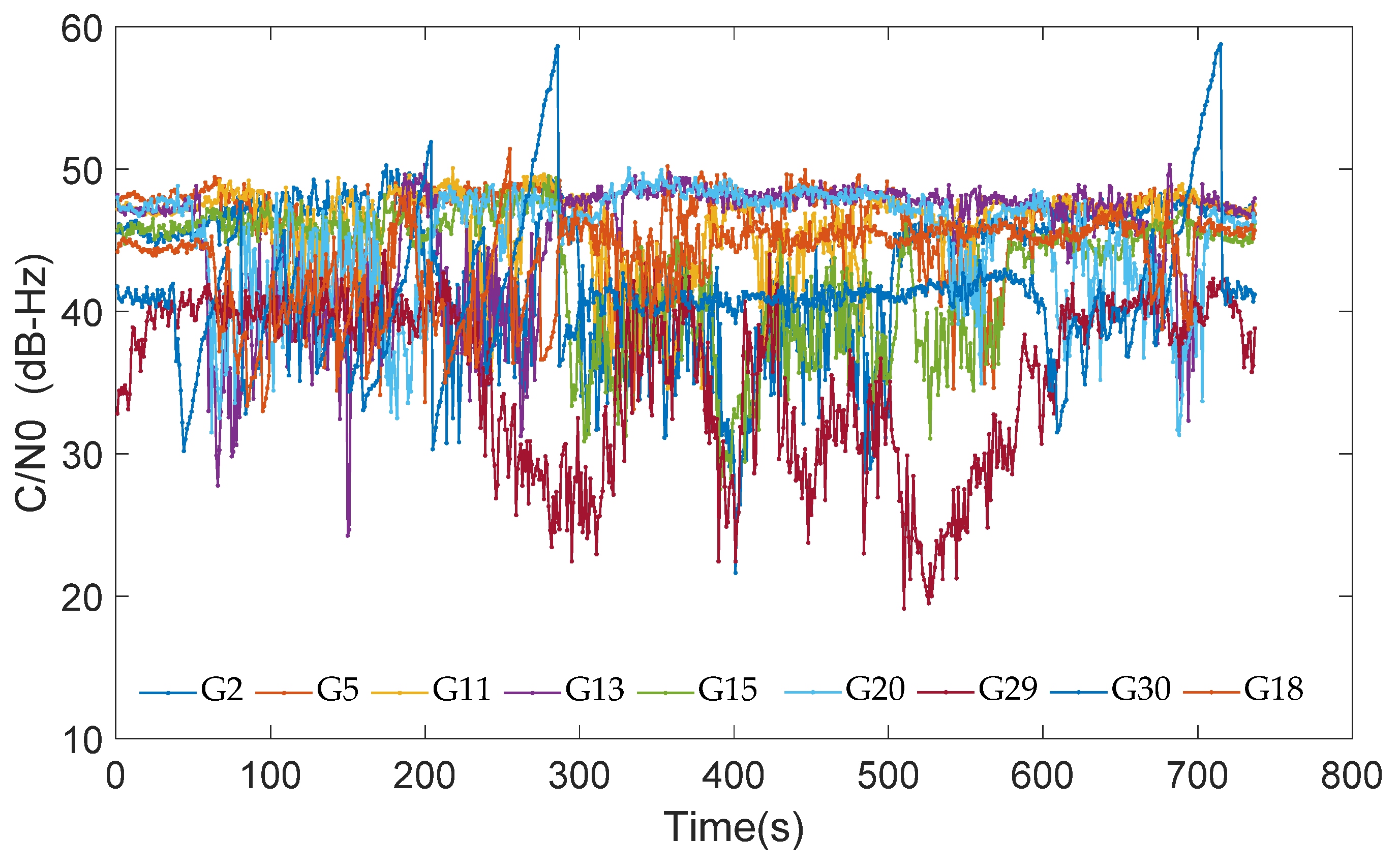
The
of the satellite signal is shown in
Figure 11. Due to the unsatisfactory observation environment, the number of satellites is maintained at about 8. However, the loss of satellite signal occurred frequently; the carrier-to-noise ratio of a few satellites is lower than 30 dB-Hz most of the time, such as G29 and G15. The position and position covariance results calculated by the carrier smoothing pseudo-range SPP are used in the measurement update of the EKF in the proposed scheme, and the adaptive algorithm is used for quality control.
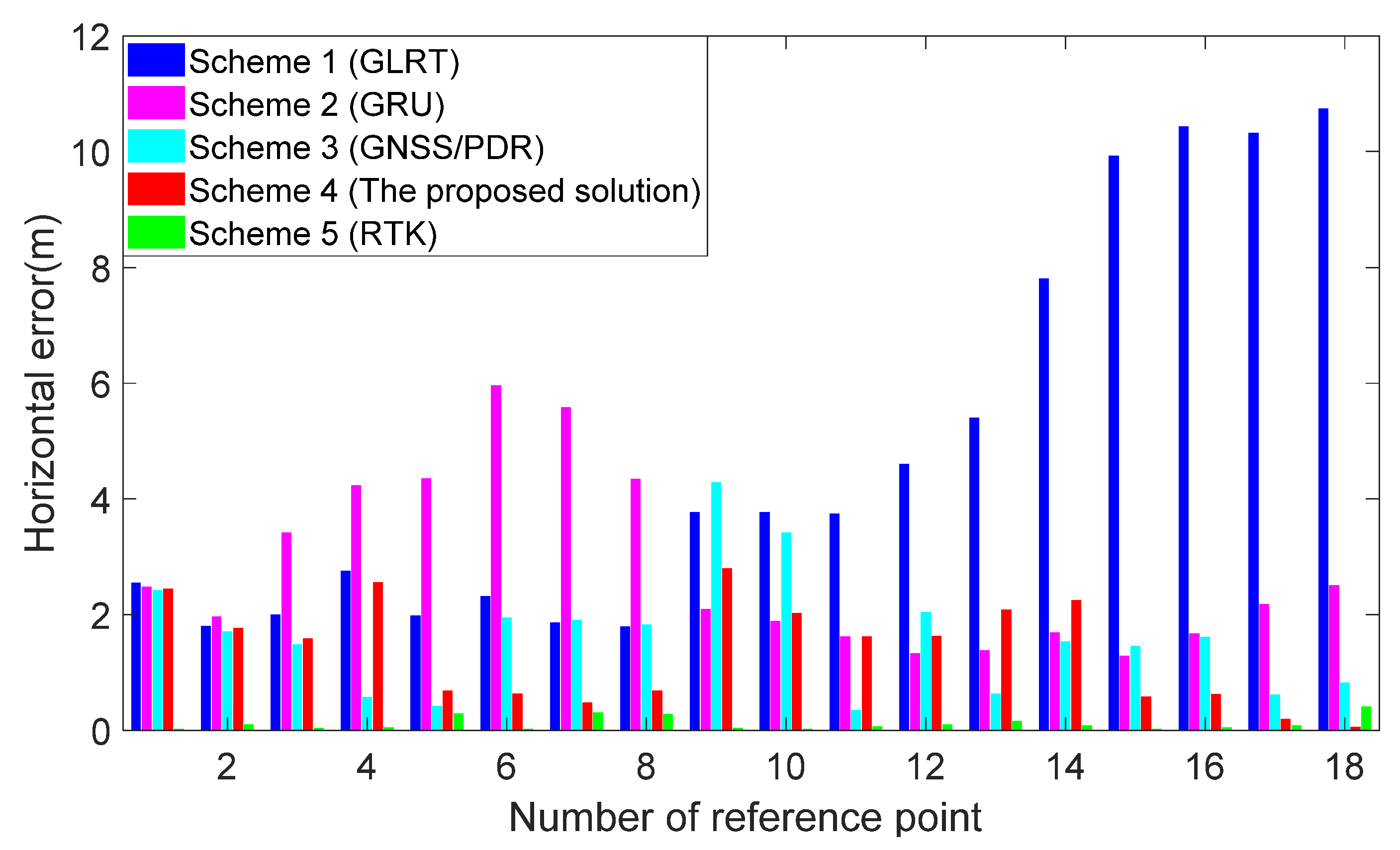
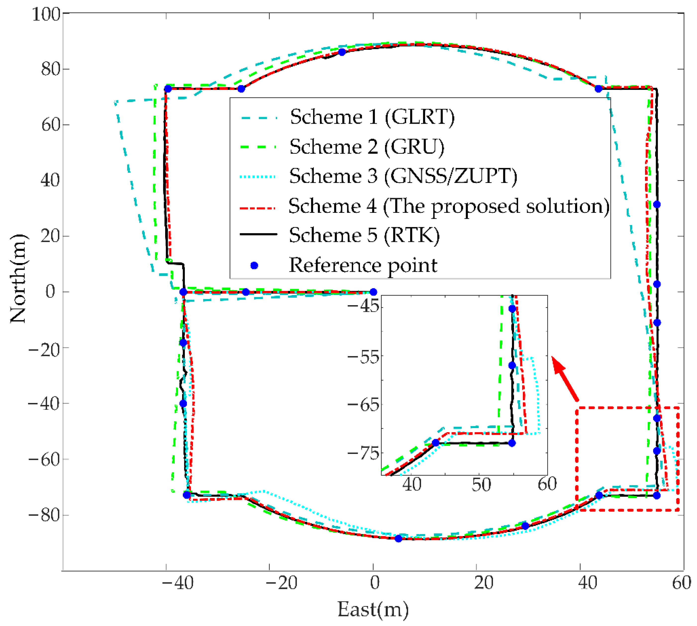
Eighteen key positions of the trajectory are selected as reference points; their position coordinate is accurately determined. Five schemes are compared. Scheme 1: use GLRT method to detect the zero-velocity interval; Scheme 2: use GRU method to detect the zero-velocity interval; Scheme 3: GNSS/PDR without adaptive algorithm; Scheme 4: the proposed algorithm; Scheme 5: RTK solution provided by mosaic-X5. The trajectories of these five schemes are shown in
Figure 12.
As shown in
Figure 13, although the position environment is complex, the horizontal error of RTK is lower than 0.5 m at all of the reference points. Because of the high precision of RTK, the trajectory of RTK is taken as the reference trajectory. In
Figure 13, we randomly select 18 points in the test path to test the accuracy of the algorithm. The proposed algorithm obtained lower position error than Schemes 1–3 at most of the reference points, noting that when the INS obtained a large error, the adaptive algorithm may increase the position error of the GNSS/PDR algorithm, such as the position error at reference point 4. However, in most cases, GNSS has larger position error than INS due to environmental interference; the adaptive algorithm can effectively decrease the position error when GNSS obtained larger error, such as the position error at reference points 6, 7, and 8. The position error of Schemes 1–4 is shown in
Table 4. It can be seen from
Table 4 that the RMSE of the four schemes are 6.08 m, 3.21 m, 1.79 m, and 1.37 m respectively and the maximum errors of the four schemes are 11.48 m, 6.02 m, 4.98 m, and 2.79 m respectively. Compared with the other three schemes, RMSE of the proposed scheme are decreased by 77%, 57%, and 23% respectively and the maximum errors of the proposed scheme are decreased by 75%, 53%, and 43% respectively. CDF of the horizontal error are shown
Figure 14. It can be seen from
Figure 14 that 99% of the horizontal error of the proposed scheme is smaller than 2.71 m. For several algorithms used to compare with the proposed scheme, some algorithms do not integrate GNSS position information, so the result obtained will be better than the proposed algorithm, but due to the characteristics of inertial navigation, the accuracy of these algorithms will diverge over time. Generally speaking, the accuracy of the proposed algorithm is better than other algorithms.
4.4. Indoor Elevation Performance Verification of the Proposed Algorithm
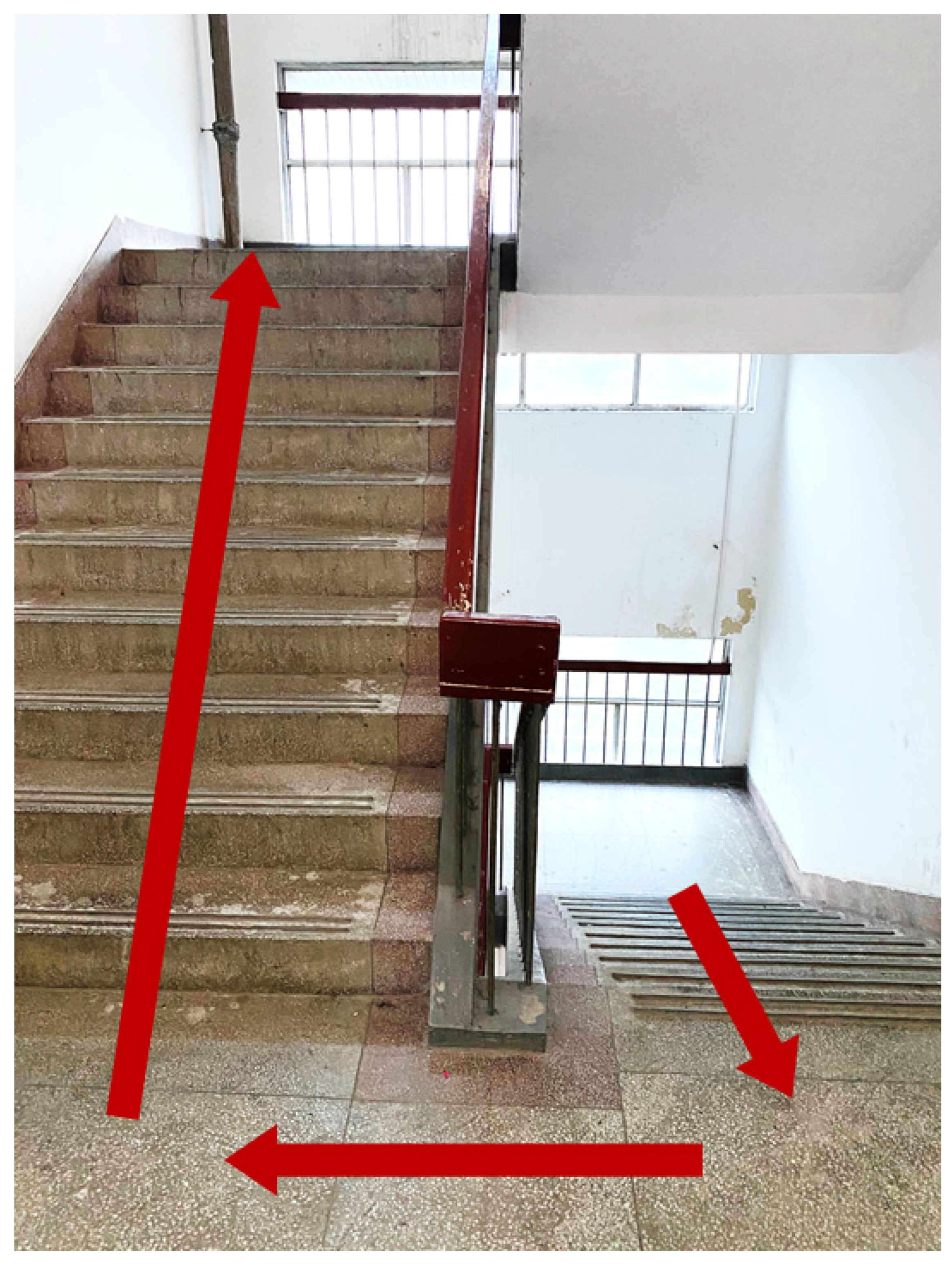
An indoor staircase environment is carried out to verify the elevation performance of the proposed algorithm. The proposed algorithm will not execute GNSS measurement update as there is no GNSS signal in the indoor environment. The experimental site is shown in
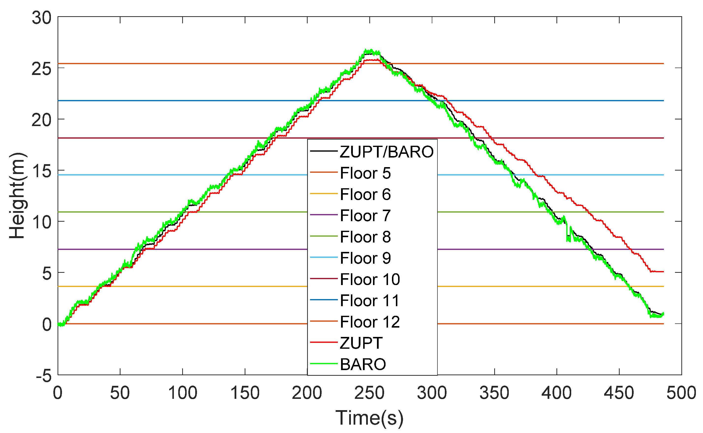
Figure 15 in this experiment; the experimenter went upstairs from the fifth floor to the twelfth floor, then went downstairs to the fifth floor. The height difference of each floor has been determined in advance by multiple measuring and only counts the elevation error when the experimenter falls on each floor of the staircase. Three schemes are compared. Scheme 1: use ZUPT to judge elevation; Scheme 2: use the barometer to judge elevation; Scheme 3: ZUPT/ barometer fusion algorithm. The test result is shown in
Figure 16.
It can be seen from
Figure 16 that the barometer can basically reflect the elevation, but the robustness is not enough, and there are many burrs. ZUPT has no large burrs, but the error diverges with time. The result of the adaptive combination of the PDR and barometer can reflect the elevation well without large error. As shown in
Table 5, RMSE of these three schemes are 1.62 m, 1.25 m, and 0.96 m, respectively. The maximum errors of these schemes are 3.3 m, 1.95 m, and 1.28 m, respectively. Compared with other two schemes, RMSE of the proposed scheme are decreased by 41% and 24%, respectively, and the maximum errors of the proposed scheme are decreased by 61% and 34%, respectively.


 ,
, 


