Article

Design and Analysis of a New Deployable Docking Mechanism for Microsatellites

1
Harbin Institute of Technology, School of Mechatronics Engineering, Harbin 150080, China
2
State Key Laboratory of Robotics, Shenyang Institute of Automation, Chinese Academy of Sciences, Shenyang 110016, China
3
University of Chinese Academy of Sciences, Beijing 100049, China
*
Author to whom correspondence should be addressed.
Remote Sens. 2022, 14(19), 5002; https://doi.org/10.3390/rs14195002
Submission received: 20 August 2022 / Revised: 30 September 2022 / Accepted: 3 October 2022 / Published: 8 October 2022
(This article belongs to the Topic Micro/Nano Satellite Technology, Systems and Components)

Abstract

:
In-orbit docking technology of microsatellites to realize combined reconfiguration has a wide application prospect, such as large antennas and space telescopes. In order to reduce collision impact and improve docking accuracy, a new deployable docking mechanism is proposed based on the slider-crank principle, which has the advantages of smaller volume and larger posture tolerance. To achieve large capture tolerance and increase the success rate of docking, the posture error is analyzed by considering the specific boundary of the position and pose. And a step-by-step cooperative capture strategy is proposed to complete the velocity selection and action matching among multiple capture arms. The reliable docking of posture correction in the docking process is realized by designing the action path of the docking mechanism. The effects of tolerance capture under different initial posture conditions are analyzed by dynamic simulation. The effectiveness and superiority of the step-by-step cooperative capture strategy are valid by comparison with the synchronized capture strategy. The comparison results show that the impact force is reduced by 8% than the synchronized strategy. The capture experiments are carried out to verify the docking performance. The results show the proposed configuration with a step-by-step cooperative capture strategy achieves successfully reliable capture, weak impact, and large posture tolerance under eight extreme initial pose conditions.

Graphical Abstract

1. Introduction

Multiple microsatellites can realize combined reconfiguration through rendezvous and docking to complete on-orbit assembly and service, such as large antennas and space telescopes [1,2,3]. Rendezvous and docking technology is the process of rendezvous of two satellites in orbit at a certain relative velocity to achieve a rigid connection and become structurally integrated [4,5,6,7]. The deployable docking mechanism is one of the most important transmission components in the docking system, ensuring the rigid connection between two satellites [8,9,10]. They are mainly used to complete tasks such as on orbit maintenance, fuel injection, modular replacement, and configuration optimization among satellites. The performance of the docking mechanism directly determines the dynamic characteristics of the docking process and the success or failure of the docking. With the diversification and complexity of on-orbit missions, the deployable docking mechanism with single locking and release function can no longer meet the requirements for multiple repeated locking of microsatellites in complex operations. The satellite deployable locking mechanism with large bearing capacity, low impact, high capture accuracy, repeatable connection and separation is one of the problems that need to be solved urgently for future space missions.
Considering the space mission requirements, the docking process is expected to ensure large tolerance, high docking accuracy, joint strength, stiffness, and synchronization. Currently, three main categories of docking technologies have been proposed for microsatellites: electromagnetic, peripheral type, and central type (probe-cone type). The electromagnetic docking technology using inter-craft non-contact forces has been the focus of research due to the advantages of no propellant consumption and flexible docking. However, it has the disadvantages of the small relay, short action distance, high energy consumption and cumbersome separation process [11,12,13]. The docking mechanisms using contact forces are more suitable for microsatellites due to their relatively large tolerance and bearing capacity. In [14,15], a docking mechanism with three arm grapple is developed and tested for microsatellites. In [16], a docking methodology for nanosatellites is proposed to improve the reliability of the docking mechanism. In [17,18], the probe–cone structure is introduced, which can achieve a rigid connection between two satellites and have a soft docking feature using an integrated electromagnet. In [19], an androgynous docking interface is developed for CubeSats. An asymmetric docking mechanism with the structure of three petals can lock the object interface to achieve a rigid connection. In [12], the androgynous docking interfaces are developed for microsatellites. A morphing grasper of the interface can insert the other interface acting as a handle to operate docking. In [20], a docking mechanism is designed to capture the interface ring to repeatedly hold, press, lock, and release the satellites. In [21], a miniature docking mechanism with a traditional probe–drogue configuration is proposed for nanosatellites, effectively easing the self-alignment between the docking interfaces. In [22], a new docking mechanism with a deployable boom is proposed. The flexible boom improves a docking approach that is robust against GNC errors. The peripheral docking mechanism has good versatility and can meet the high-strength bearing, but the overall configuration is complex and the system quality is high. The central docking mechanism is simple in structure, light in weight, and has a relatively large tolerance capacity. However, these mechanisms all need specific interfaces, their volume and quality are relatively large, and their structures are also relatively complex. The research on universality, low impact force, high capture tolerance and other aspects is insufficient.
The main motivation of the paper is to propose and test a new deployable docking mechanism for microsatellites to achieve high tolerance and low impact collision in the docking process. The main novelties and contributions lie in two aspects. On the one hand, a new structure with a smaller volume and a greater capture space is proposed based on the slider-crank principle. On the other hand, a step-by-step cooperative capture strategy is proposed and effectively reduced the impact force between two microsatellites. The remaining parts are organized as follows. Section 2 introduces the configuration and working principle of the new docking mechanisms for the microsatellites. The features and merits are summarized. Section 3 analyzes the position and attitude error and deployment velocity of the docking mechanism. A step-by-step cooperative capture strategy is presented for a low impact force and high tolerance docking. Section 4 analyzes the motion and force characteristics of the proposed mechanism by the docking process simulation. The simulated prototype of the docking mechanism is developed and the text platform is established. The docking performance and capture strategy are verified by the experiment with gravity compensation.

2. Structure and Working Principle

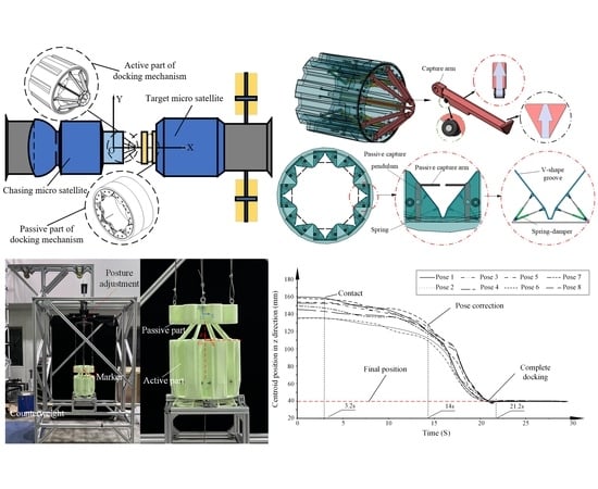
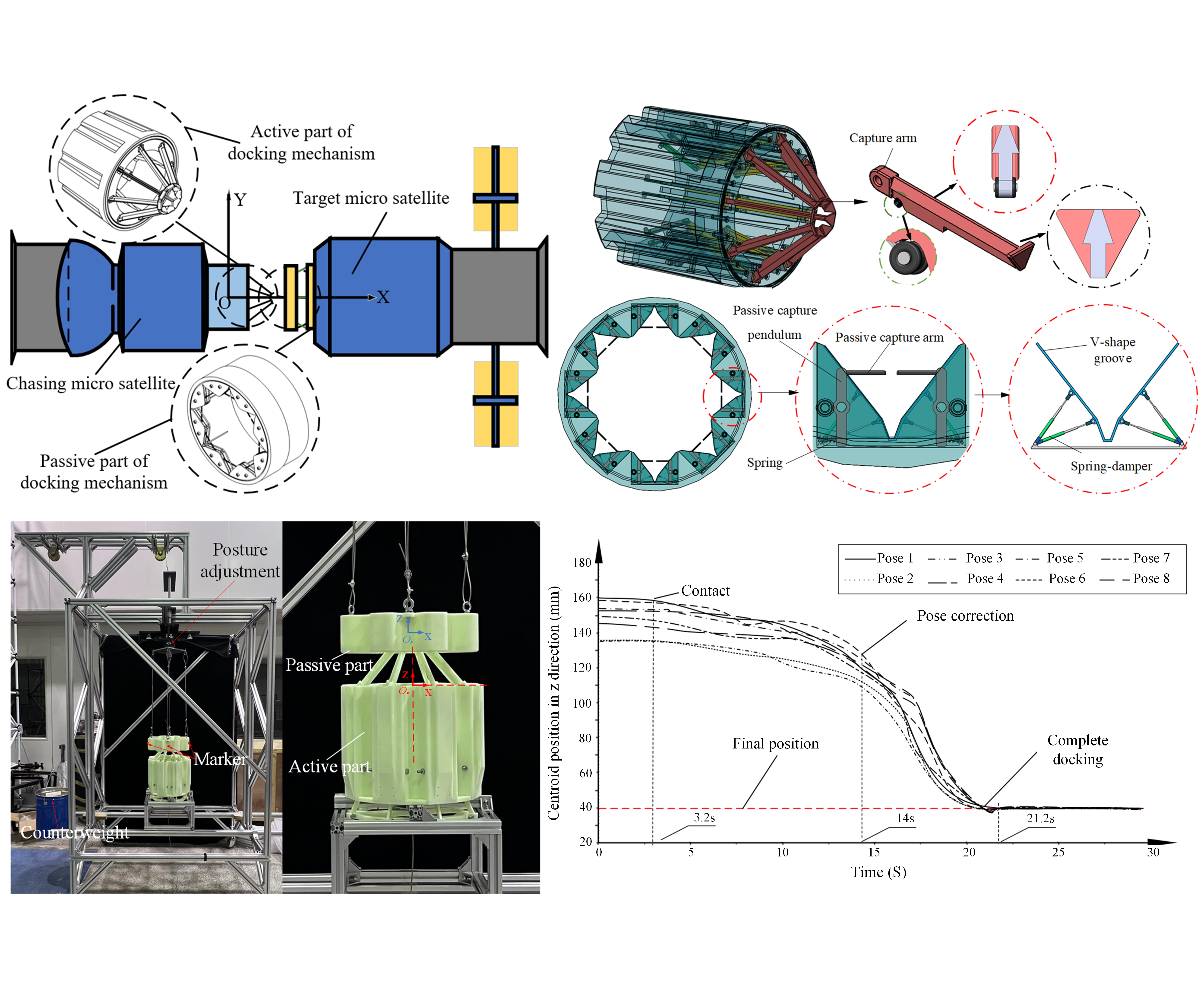
2.1. System Composition

The proposed deployable docking mechanism mainly consists of an active part mounted in the chasing satellite and a passive part mounted in the target satellite, as shown in Figure 1 and Figure 2. The active part mainly contains the drive assembly, the capture assembly, and the locking assembly. Drive assembly provides locking torque for clamping and unlocking torque for separation. The capture assembly main contains a slider-crank mechanism and capture arm. The passive part mainly includes a V-shape groove and passive capture assembly. The V-shape groove is applied for reducing the impact force from the capture arm and the posture correction of the target satellite. The passive capture assembly is used to limit the capture arm position once the capture is complete. As the chasing satellite slowly approaches the target satellite to the initial position, the capture assembly completes the catch of the target satellite.

2.2. Working Principle

Figure 3 shows the docking process includes four stages: (a) access to the capture range, (b) capture arm swing, (c) posture correction, and (d) capture locking.
(a)
Access to the capture range. The capture arms are arranged at a fixed angle to the docking axis. And the passive part of the docking mechanism is extended by a six-degree-of-freedom platform. So, the capture arm of the active part is placed within the tolerance space at the passive part of the docking mechanism.
(b)
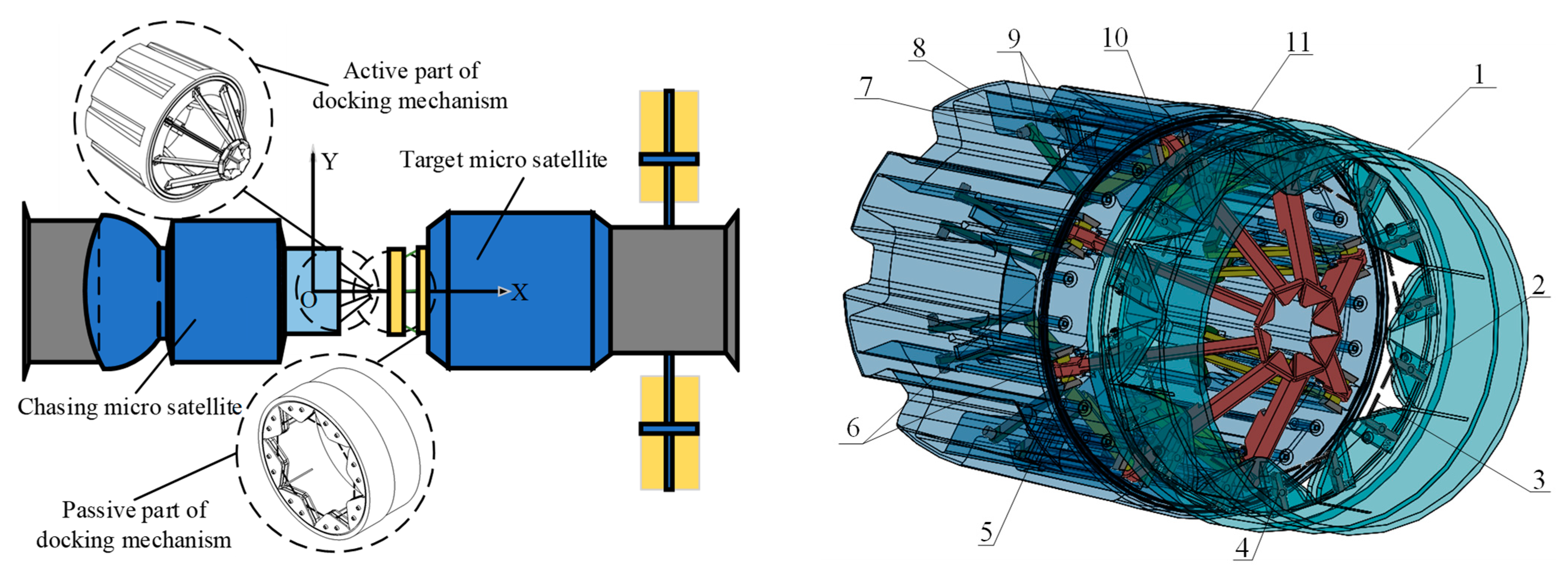
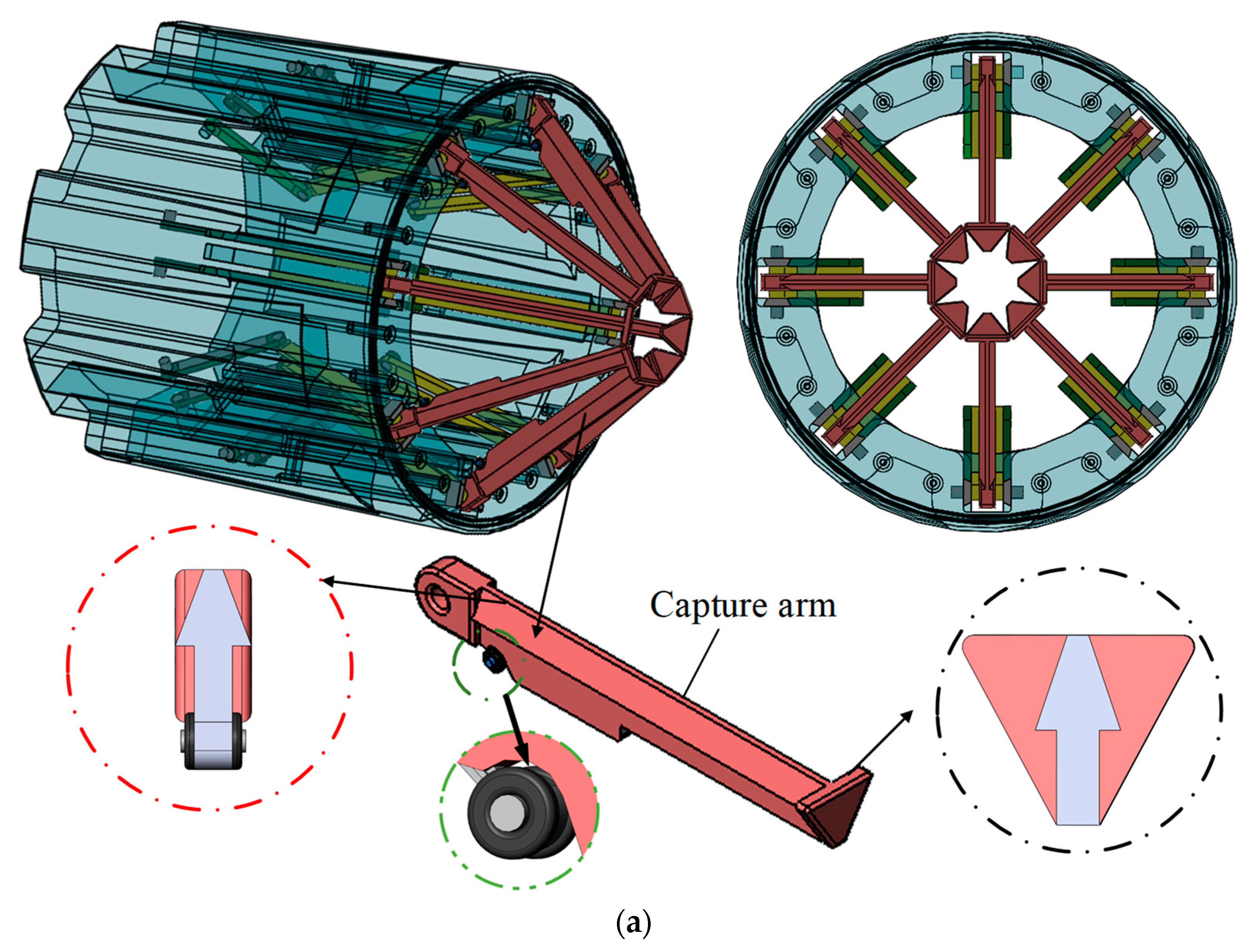
Capture arm swing. The crank slider module starts to work and all capture arms are simultaneously aligned along the direction away from the axis. Then, the capture arms are first in contact with the passive part of the docking mechanism on the target satellite.
(c)
Posture correction and approach. As the bevel of the capture arm squeezes the spring after contacting the bevel of the passive rocker, the passive rocker moves closer to the sides of the V-shape groove. When the capture arm ends contact with the bevel of the passive rocker, the spring springs back and the passive rocker catches the capture arm to achieve reliable capture. The capture arm is in continuous contact with the V-shape groove to achieve attitude correction between the two satellites.
(d)
Capture locking stage. The crank continues to rotate under the action of the motor, and the capture arm moves backward following the slider. The capture arm drives the target satellite to approach the chasing satellite. The seal ring on the docking frame of the chasing satellite contacts the docking frame of the target satellite and continuously squeezes the seal ring and the axially arranged disc spring on the docking frame to complete the application and sealing of the locking force between the two satellites. The six-degree-of-freedom docking platform at the end of the passive part is simultaneously retracted into the satellite, and the crank-slider mechanism achieves reliable self-locking.
The features and merits of the proposed docking mechanism can be summarized as follows: (1) Good pose tolerance. In the case of attitude and position error between the chasing satellite and target one, the active part of the docking mechanism can still be successfully extended into the capture space of the passive part. (2) Low axial collision impact. The deployable docking mechanism avoids the traditional way of capturing two satellites by colliding with each other at relative axial velocities, avoiding the excessive axial impact loads caused by the traditional collision capture method, reducing the requirements of the buffer system in the docking system, and reducing the overall mass of the docking system. The deployable docking mechanism is symmetrically distributed, and the capture arm swing speed and friction plate are adjusted to cushion the inevitable circumferential impact during capture.

3. Collaborative Capture Strategy

3.1. Positional Posture Error Analysis

The positional tolerance of the docking mechanism can be expressed as: R max = [ ± x m , ± y m , ± z m , ± α m , ± β m , ± φ m ] . The six parameters in the tolerance R max represent the lateral, longitudinal, and axial translation errors and pitch and roll errors in the initial conditions of docking, respectively. To facilitate the analysis, each parameter is represented by only two extreme values, positive and negative. When the minimum or maximum value of each parameter is taken, the boundary positional posture error e m i can be obtained. Six parameters can obtain Q = 2 6 = 64 boundary error positions, where each boundary position corresponds to an initial attitude of the docking mechanism p m i . For example, if the maximum value of all Six parameters is chosen, the boundary positional posture error e m 1 is:
e m 1 = [ x m , y m , z m , α m , β m , φ m ]
When one type of positional posture error e m i = [ x i , y i , z i , α i , β i , φ i ] ( i = 1 , 2 , 64 ) between the satellite and the docking mechanism tolerance capacity R max satisfy Equation (2), it is determined that the docking mechanism can overcome the initial positional posture error to achieve capture.
{ x m x i x m , y m y i y m , z m z i z m α m α i α m , β m β i β m , φ m φ i φ m
When all 64 positional posture errors e m i between satellite satisfy Equation (2), it is determined that any error position within the docking mechanism tolerance R max can be effectively captured. To verify the docking mechanism tolerance capability by capturing the docking mechanism attitude p m i corresponding to the boundary positional posture error e m i , it is necessary to verify the docking mechanism attitude for 64 boundary positional posture errors. To simplify the calculation, the characteristics of the boundary positional posture errors are analyzed as well as classified and simplified.
The active capture arms of the active part are arranged at 45° intervals, and the overall layout has the characteristic of being centrally symmetric. The set of 64 boundary error positions of the deployable docking mechanism is shown in Figure 4. The boundary error positions are centrosymmetric. The variable-controlling approach is applied to analyze the translation errors of the docking mechanism in x, y, and z directions individually. The initial condition parameters x i , y i , and z i take positive and negative extremes, respectively.
The movement of the docking mechanism attitude in the axial direction of docking is shown in Figure 5a for changing parameter z i alone, including parameter y i , z i , α i , β i , φ i . It can be seen that the longer the axial length d of the capture arm of the active part of the deployable docking mechanism extending into the docking frame of the target satellite in the axial direction of docking is more favorable for docking capture. During the analysis of the parameter x i , the extreme case where the active part of the docking mechanism is far from the docking frame of the target satellite was chosen for analysis. The positional situation of the docking mechanism in the docking cross-section by varying parameters x i and y i separately and including parameter x i , α i , β i , φ i is shown in Figure 5b,c, which shows that the movement error of the docking mechanism in the y-direction is symmetric about the z-axis and the movement error positional attitude of the docking mechanism in the z-direction is symmetric about the y-axis.
The 64 boundary positional postures of the docking mechanism can be simplified. Simplify the initial docking conditions parameters in the x, y, and z-axis translation errors, and consider each translation error under only one situation. In the z-axis direction, only the case of the active part away from the passive part of the docking frame is considered. In the x-axis direction and y-axis directions, only consider the error positive polarity. Along the x, y, and z-axis pitch, positive and negative polarity are considered for roll error. Then, 64 kinds of error cases can be simplified into 8 kinds of key positional posture errors, the specific positional posture error parameters are shown in Table 1. The 8 key error positional cases will be analyzed in the next text.
According to the center-symmetric layout of the central deployable docking mechanism, the influence of the error parameters of the initial docking conditions on the initial positional posture error is analyzed. The movement errors of the three docking surface axes are effectively and reasonably simplified. The influence of the pitch and roll errors on the boundary positional posture in the docking surface coordinate system is mainly analyzed to lay the foundation for the subsequent simulation analysis and experimental verification of the docking capture strategy.

3.2. Capture Arm Deployment Speed Analysis

Capture arm deployment speed is an important motion parameter in the docking and capturing process, which determines the collision impact of the docking and capturing process. It has an important impact on the smoothness of the motion. The capture arm deployment process can be divided into slow mode and fast mode. In the slow mode, the posturing process of the capture arm and the V-shape groove capture is relatively gentle, and the relative speed and contact force are low. The damping effect of the six-degree of freedom posture platform behind the passive part of the docking mechanism ensures that the passive docking frame is always in contact with the capture arm without separation. The slow deployment mode can effectively reduce the collision impact and the docking system requirements for the buffer mechanism, and further reduce the probability of equipment damage by impact. However, the slow deployment mode leads to a long docking mechanism work time, increasing the docking system energy consumption. In the fast mode, multiple capture arms unfold rapidly at the same time, and the capture arms collide with the V-shape groove at a high relative speed during the movement, resulting in a large collision impact. Due to the initial position error, multiple capture arms collide at different moments, resulting in a second collision. Then after multiple collisions, multiple capture arms unfold to the bottom of the V-shape groove to complete the capture and attitude of the passive docking frame. In this mode, the capture process requires high buffering capacity for the docking mechanism system, and the multiple collision impact increases the probability of equipment damage. Fast capture can effectively reduce the working time of the capture process and reduce system energy consumption.
The main difference between the slow mode and the fast mode is not only the difference in docking capture time but also the difference in collision impact. The main factor affecting the smoothness of the docking process is the impact force, which is obtained from the law of conservation of momentum as:
m 1 V 1 + m 2 V 2 = m 1 V 1 + m 2 V 2
where m 1 and m 2 are the masses of colliding object 1 and object 2, respectively.
The impulse generated by the collision of the docking mechanism capture arm deployment process is related to the initial state of the docking mechanism as:
P = ( 1 + S ) m 1 m 2 m 1 + m 2 Δ v
where P is the collision impulse (Ns) and Δ v is the relative velocity (mm/s) of the capture arm before collision with the V-shape groove.
During the docking mechanism capture, the mode of the capture arm deployment speed is selected as fast deployment slow contact mode.

3.3. Cooperative Capture Action Matching

The docking mission of the active and passive parts are in the harsh and complex deep space environment for a long time, and the respective docking systems need to repeat the in-orbit docking task. The relative speeds of the active and passive ends of the docking mechanism during the docking action will cause the capture arm and its drive mechanism to be continuously subjected to collision impact. Due to the long-term thermal alternating environment in deep space, the capture arm and its back-end four-bar drive mechanism are subject to a certain degree of deformation due to alternating hot and cold temperatures, resulting in a reduction in the dimensional accuracy of the docking mechanism. These conditions aggravate the instability of the docking mechanism in the working process.
The collision impact during the docking process can be effectively reduced and the stability of the docking process can be improved by adjusting the capture strategy. The synchronous capture strategy of the docking mechanism has the advantages of short capture time and high efficiency in the ideal docking collision state. However, since the initial docking error is unavoidable, the corresponding capture strategy still needs to be specified for the key boundary error positions. The capture strategy is to match the motion parameters of the active part of the docking mechanism after recognizing the initial docking boundary error positions of the passive part, including the action sequence of the eight capture arms, the deployment speed of the capture arms, and the motor speed of the drive assembly. The active capture arm deployment speed is related to the size of the collision impact during docking and capturing. The action sequence of the capture arm affects the posture of the docking frame at the passive part during the capturing and docking process. The motor speed of the drive component also affects the synergistic effect of multiple capture arms.
An effective capture strategy can reduce the initial docking positional posture error of the docking mechanism and improve dynamic stability and reliability. Considering a variety of key boundary error positions, a step-by-step cooperative capture strategy is proposed based on sensing for fast deployment and slow contact. According to the contact information between the capture arm and the V-shape groove sensed by the docking mechanism system through the action of the eight capture arms in cooperation, the specific motion parameters of the capture arm are matched, including the movement sequence of the capture arm and the deployment speed.
Figure 6 shows the eight capture arms of the active part of the docking mechanism are divided into two groups. Group ① and group ② are composed of four capture arms arranged at intervals, and the capture arms in each group are distributed along the circumference at 90° intervals. In the process of synchronous docking and capturing, the eight capture arms move at the same time with the same unfolding speed. Due to the positional posture error, the eight capture arms are not synchronized with the capture frame at the passive part of the docking mechanism, resulting in multiple collisions between the capture arms and the V-shape groove. The capture arms close to the tracking docking frame are hinged to the slider with severe vibration, which significantly reduces the stability of the docking capture work. Therefore, for different docking boundary positions, the two sets of capture arms are moved in different orders. Take a key boundary error position as an example, as shown in Figure 7. The deviations of the two capture arms from the ideal position separately are analyzed. It can be noticed that among the four capture arms in group ①, the positions of a, b, c, and d deviate more from the expected position, while the positions of h and g capture arms in group ② deviate more from the ideal position. Comparing the attitude of group ① and group ②, the overall positional posture error of group ② is better. The first step of the capture arm of group ② is selected to deploy rapidly and contact slowly, while group ① remains relatively stationary, and when the capture arm of group ② finishes capturing and adjusting the attitude of the passive docking frame, the capture arm of group ① is deployed rapidly. This step-by-step capture strategy can effectively reduce the number of collision points and collisions in the docking mechanism capture process, thus reducing the collision impact and improving the smoothness of the capture and docking process.
The specific action sequence of the step-by-step capture strategy is: in the initial state of docking, drive the slider of one group of capture arms to move at the same speed and keep the other group of capture arms stationary. Capture arms e, f, g, and h expand at the same angular speed, once the four capture arms are in contact with the docking frame, they stop, which means the end of the fast expansion action. When the capture arm e, f, g, and h are completed in the docking frame contact, the sliders of capture arm e, f, g, and h slowly are driven at the same time, meaning the beginning of slow contact action. The four capture arms collide and contact with the docking frame and adjust the attitude of the docking frame and then fully expand and remain stationary, which means the end of step-by-step capture. Another group of stationary capture arms a, b, c, and d is driven to quickly unfold. After all capture arms are deployed, all sliders of capture arms are driven to move at a uniform speed to achieve capture, adjustment, approach, and lock steps, and complete the docking work.
In the step-by-step capture stage, the first four capture arms are moving at a velocity of v m . The displacements of the four capture arms when they deploy and contact the docking frame are x e , x f , x g , and x h . Due to the initial docking positional posture error, the capture arms e, f, g, and h come into contact with the docking frame in turn and then come to rest, with the capture arm g touching the docking frame first, and this phase can be expressed as:
{ v e = v m v f = v m v g = v m v h = v m ( 0 t x e v m )
The capture arm g comes to rest after contact, and the capture arm h then contacts the docking frame. This phase can be expressed as:
{ v e = v m v f = v m v g = 0 v h = v m ( x e v m t x h v m )
The capture arm g, h comes to rest after contact, and the capture arm f then contacts the docking frame. This phase can be expressed as:
{ v e = v m v f = v m v g = 0 v h = 0 ( x h v m t x f v m )
After the capture arms g, h, and f come to rest, the capture arm e then contacts the docking frame. This phase can be expressed as:
{ v e = v m v f = 0 v g = 0 v h = 0 ( x f v m t x e v m )
where v e , v f , v g , v h are velocities of capture arms e, f, g, h.
Then the capture arms e, f, g, and h move at the same speed v n and remain stationary after adjusting the docking frame attitude cooperatively. The second group of capture arms a, b, c, and d are deployed at the speed v m , and the step-by-step capture ends when all capture arms are completed.

4. Simulation and Experiment Investigation

The capture, attitude correction, approach, and locking functional characteristics of the docking mechanism in the positive touch attitude case and in the error attitude conditions are analyzed by simulation. Then, the synchronous docking capture and cooperative docking capture characteristics are compared by simulation. The scaled prototype and the test platform are developed. And the experiments with gravity compensation are implemented to verity the docking characteristics.

4.1. Positive Bump Docking

Positive bump docking refers to the ideal situation where there is only a defined axial approach velocity between the two docking compartments, and the rest of the initial docking attitude error and velocity error are zero. For the ideal positive touch docking situation, the initial docking conditions are set as shown in Table 2. The simulation analysis mainly examines the ability of the active part of the docking mechanism to capture attitude correction, the buffering capability of the passive part, and the displacement and force. The docking model is set up with the passive part of the docking mechanism installed in the front of the target satellite channel. The passive part of the docking mechanism is installed with a six-degree-of-freedom docking platform to adjust the initial docking attitude. The platform is in a free-floating follower state after reaching the initial docking conditions.
As shown in Figure 8, the active part of the docking mechanism starts to contact the passive part of the V-shape groove and buffer mechanism for the first time after 9.7 s. The target satellite starts to approach the chasing satellite under the action of friction between the capture arm and the V-shape groove. The position of the target satellite is adjusted at the same time during the approaching process. At this time, the disc spring and docking frame start to squeeze each other to achieve the channel seal between the satellites. The docking and locking action is completed around 90 s.
As shown in Figure 9, after the first contact collision between the chasing satellite and the target satellite in the positive docking condition, the kinetic energy of the chasing satellite decreases from 147 Nm to 70 Nm, while the kinetic energy of the target satellite increases from 0 Nm to 30 Nm. The kinetic energy of the whole system decreases by about 31.9%. The overall kinetic energy of the system decreases by 40.9% after the attitude correction between them. Figure 10 shows that the system velocities of the active and passive parts of the docking mechanism fluctuate, and finally stabilize at about 0.05 m/s after docking.
The contact force of the four V-shape grooves at the passive part of the docking mechanism is shown in Figure 11. Due to the 100 mm lateral error in the initial docking, the contact time between the capture arm and the V-shape groove is not synchronized. The maximum force peak of the four V-shape groove is 6400 N. The force of the V-shape groove gradually decreases and stabilizes in the range of 1000–1200 N during the process of attitude correction of the capture arm of the docking mechanism.

4.2. Error Position

Based on the results of the key positional posture error analysis in Section 3.1, the tolerance, attitude correct ability, and buffering capabilities of the docking mechanism in the presence of extreme positional errors are analyzed.
As shown in Figure 12, the active part of the docking mechanism makes contact with the passive part at about 9.4 s. During the process of the multiple capture arms of the active part entering the V-shape groove, the attitude of the target satellite is corrected in real-time and remains basically stable after the position correction. The displacement in the z-axis direction changes smoothly as the target satellite is pulled closer by the docking mechanism until the displacement stops at the locking end. The initial docking conditions of the simulation analysis for eight initial pose conditions are listed in Table 3.

4.3. Capture Strategy Analysis

The contact forces of synchronous docking capture and the proposed cooperative docking capture are compared and analyzed in the simulation, and the initial docking conditions are shown in Table 4. The docking mechanism model in the simulation environment is shown in Figure 12. As shown in Figure 13 and Figure 14, the contact time between the capture arm and the V-shape groove is not synchronized due to the positional posture error, and the peak force of the V-shape groove is 6500 N. The duration of the peak force is short, and the final force of all V-shape grooves is stable at about 1000 N. In the process of cooperative capture, two sets of capture hooks perform swinging action one after another, and the first set of capture hooks interacts with the V-shape groove to achieve buffering and attitude adjustment functions. The cooperative acquisition strategy avoids different initial attitudes of docking and adjusts the movement sequence of the acquisition arm. The peak force is around 6000 N. The target satellite attitude is corrected during the slow swinging process. The buffering force of the V-shape groove is stabilized at around 1000 N during the process of pulling in the target satellite. After the attitude correction, the second group of capture arms is slowed down and the peak contact force with the corresponding V-shape groove is about 2800 N. Finally, the force on the second group of V-shape grooves is fast and stable at about 1000 N. The comparison results show that the cooperative capture strategy can effectively reduce the collision forces during the capture process while ensuring the functions of capture and attitude correction.

4.4. Experimental Verification

The docking test bench is used to experiment with the capture, attitude correction, docking, and other actions of the designed central deployment docking mechanism and to verify the superiority of the cooperative capture strategy. Its main functions include a four-degree-of-freedom posture simulation with the platform that can provide pitch, roll three degrees of freedom of rotation, and z-directional translation. The sliding rail of the lower active part of the docking test stand frame provides freedom of translation in x and y directions. The counterweight ensures the passive part of the docking mechanism hovers in a specific error position.
The four-degree-of-freedom posture simulation follower platform is shown in Figure 15, which has four degrees of freedom to realize the simulation of pitch, roll, yaw motion, and z-direction motion of the passive part of the docking mechanism.
Active part and passive part docking compartments are made by 3D printing. The scaled-down models of the active and passive parts of the docking mechanism are designed with reference to the dimensions of the real docking compartments, where the active part of the docking mechanism is shown in Figure 16. The capture and docking experimental rigs are shown in Figure 17. The relative position and posture between the active and passive parts are adjusted by the posture adjustment. According to the coordinate system of the docking test bench, the coordinates of the center of mass of the passive part are calculated in eight initial postures using the active part face coordinate system as the global coordinate system. The initial coordinates of the center of mass of the passive part after the initial condition transformation coordinates are shown in Table 5.
The position versus time along the x, y, and z directions are shown in Figure 18. The center-of-mass coordinate of the passive part is recorded by the cameras and the distance displacement sensors at all times. The center of mass position of the passive part converges to the expected position continuously without any capture failure. Figure 18a,b show there is obvious fluctuation when the capture arm of the active part contacts with the passive part. Due to the collision impact between the active part and the passive part, the mass of the passive part swings slightly around the desired position. In the experiment of the step-by-step cooperative capture strategy, the action of the active capture arms cannot be fully synchronized, which also causes unbalanced contact forces between the two microsatellites. In the pose correction process, the fluctuation of the passive part is very small, and the center of mass is basically stable at the central axis of the active part. The total time of the docking process is about 18 S in the experiments, indicating that the proposed docking can quickly correct the relative attitude of the two microsatellites. Figure 18c shows that the movement speed of the passive part in the z direction is slow and fluctuates slightly due to the impact forces between the active and passive parts in the capture process. The speed is improved in the pose correction process. The time of pose correction is about 7.2 S, which is lesser than 10.8 S of the capture process. The tolerance of the docking mechanism is verified by the experiment. In the eight extreme initial attitude conditions, the passive part of the docking mechanism can eliminate the initial attitude error in x, y, and z directions. And the cooperative capture strategy can successfully achieve the capture, attitude correction, and docking lock.

5. Conclusions

Based on the crank-slider principle, a new deployable docking mechanism is proposed for weak impact and high tolerance of docking. Considering the docking initial posture error, the boundary attitude is classified and simplified. A step-by-step cooperative capture strategy is proposed for a specific boundary attitude. The speed selection and capture arm action matching are completed. The dynamic characteristics of the docking process such as capture, attitude correction, approach, and locking are analyzed by simulation. The lower impact-collision forces are achieved through the step-by-step capture strategy. The comparison results show that the impact force is reduced by 8% than the synchronized strategy. The capture effect under different initial attitude conditions is analyzed. The scaled-down prototype of the docking mechanism is developed and the docking tests are carried out. The total time of the docking process is about 18 S in the experiments, indicating that the proposed docking can quickly correct the relative attitude of the two microsatellites. The proposed deployable docking mechanism has the advantages of light weight, high tolerance, and low impact-collision force.
In the future, in order to further improve docking accuracy and reduce impact force for space applications, we will study the influence of alternating temperature on the thermal expansion of the docking mechanism and the asynchronous motion between the bars due to friction.

Author Contributions

Conceptualization, H.Y. and F.Y.; methodology, Y.Z. and T.Y.; software, Y.Z. and D.B.; validation, D.B. and Y.Z.; formal analysis, F.Y. and X.Y.; investigation, D.B. and T.Y.; resources, H.Y.; data curation, T.Y. and X.Y.; writing—original draft preparation, Y.Z.; writing—review and editing, X.Y. and D.B.; visualization, X.Y. and F.Y.; supervision, F.Y. and T.Y.; project administration, H.Y.; funding acquisition, H.Y. All authors have read and agreed to the published version of the manuscript.

Funding

This research was funded by the National Natural Science Foundation of China (52075118).

Data Availability Statement

Not applicable.

Acknowledgments

The author would like to thank the reviewers and the editors for their valuable comments and constructive suggestions that helped to improve the paper significantly.

Conflicts of Interest

The authors declare no conflict of interest.

References

  1. Battistini, S.; De Angelis, G.; Pontani, M.; Graziani, F. An Iterative Guidance and Navigation Algorithm for Orbit Rendezvous of Cooperating CubeSats. Appl. Sci. 2022, 12, 9250. [Google Scholar] [CrossRef]
  2. Underwood, C.; Pellegrino, S.; Lappas, V.J. Using CubeSat/micro-satellite technology to demonstrate the Autonomous Assembly of a Reconfigurable Space Telescope (AAReST). Acta Astronaut. 2015, 114, 112–122. [Google Scholar] [CrossRef] [Green Version]
  3. Stesina, F. Tracking Model Predictive Control for Docking Maneuvers of a CubeSat with a Big Spacecraft. Aerospace 2021, 8, 197. [Google Scholar] [CrossRef]
  4. Zhao, X.; Zhang, S. Adaptive saturated control for spacecraft rendezvous and docking under motion constraints. Aerosp. Sci. Technol. 2021, 114, 106739. [Google Scholar] [CrossRef]
  5. Yan, W.; Bo, G.; Xiaodong, W.; Junde, W.; Chaoze, Z. Simulation of Spacecraft Cabin Automatic Docking. In Proceedings of the 2021 4th International Conference on Robotics, Control and Automation Engineering (RCAE), Wuhan, China, 4–6 November 2021; pp. 356–361. [Google Scholar] [CrossRef]
  6. Breeden, J.; Panagou, D. Guaranteed Safe Spacecraft Docking with Control Barrier Functions. IEEE Control Syst. Lett. 2021, 6, 2000–2005. [Google Scholar] [CrossRef]
  7. Yu, D.; Liu, P.; Qiao, D.; Tang, X. A Safety Prediction System for Lunar Orbit Rendezvous and Docking Mission. Algorithms 2021, 14, 188. [Google Scholar] [CrossRef]
  8. Hinkel, H.; Zipay, J.J.; Strube, M.; Cryan, S. Technology development of automated rendezvous and docking/capture sensors and docking mechanism for the Asteroid Redirect crewed mission. In Proceedings of the 2016 IEEE Aerospace Conference, Big Sky, MT, USA, 5–12 March 2016; pp. 1–8. [Google Scholar] [CrossRef] [Green Version]
  9. Luo, Y.; Sun, Z. Safe rendezvous scenario design for geostationary satellites with collocation constraints. Astrodynamics 2017, 1, 71–83. [Google Scholar] [CrossRef]
  10. Choi, J.; Jung, J.; Lee, D.; Kim, B. Articulated linkage arms based reliable capture device for janitor satellites. Acta Astronaut. 2019, 163, 91–99. [Google Scholar] [CrossRef]
  11. Shi, K.; Liu, C.; Biggs, J.D.; Sun, Z.; Yue, X. Observer-based control for spacecraft electromagnetic docking. Aerosp. Sci. Technol. 2020, 99, 105759. [Google Scholar] [CrossRef]
  12. Olivieri, L.; Francesconi, A. Design and test of a semiandrogynous docking mechanism for small satellites. Acta Astronaut. 2016, 122, 219–230. [Google Scholar] [CrossRef]
  13. Shi, K.; Liu, C.; Biggs, J.D.; Sun, Z.; Yue, X. Coupled orbit-attitude dynamics and trajectory tracking control for spacecraft electromagnetic docking. Appl. Math. Model. 2022, 101, 553–572. [Google Scholar] [CrossRef]
  14. Stamm, S.; Motaghedi, P. Orbital express capture system: Concept to reality. Int. Soc. Opt. Photonics 2004, 5419, 78–91. [Google Scholar] [CrossRef]
  15. Motaghedi, P. On-orbit performance of the Orbital Express Capture System. In Sensors and Systems for Space Applications II, Proceedings of the SPIE Defense and Security Symposium, Orlando, FL, USA, 16–20 March 2008; SPIE: Bellingham, WA, USA, 2008; Volume 6958. [Google Scholar]
  16. Ui, K.; Matunaga, S. Identification of Docking Possibility Criteria Including Recovery from Incomplete Grasping of Docking Mechanism for Nanosatellite. J. Space Eng. 2009, 2, 1–11. [Google Scholar] [CrossRef] [Green Version]
  17. Boesso, A.; Francesconi, A. ARCADE small-scale docking mechanism for micro-satellites. Acta Astronaut. 2013, 86, 77–87. [Google Scholar] [CrossRef]
  18. Barbetta, M.; Boesso, A.; Branz, F.; Carron, A.; Olivieri, L.; Prendin, J.; Rodeghiero, G.; Sansone, F.; Savioli, L.; Spinello, F.; et al. ARCADE-R2 experiment on board BEXUS 17 stratospheric balloon. CEAS Space J. 2015, 7, 347–358. [Google Scholar] [CrossRef]
  19. Bowen, J.; Villa, M.; Williams, A. CubeSat based rendezvous, proximity operations, and docking in the CPOD mission. In Proceedings of the 29th Annual AIAA/USU Conference on Small Satellites, Logan, UT, USA, 8–15 August 2015. [Google Scholar]
  20. Jianbin, H.; Zhi, L.; Bo, M.; Xu, H.; Yujia, P.; Longfei, H. Dynamic modeling and analysis of docking the GEO satellite interface ring. In Proceedings of the 2017 IEEE International Conference on Robotics and Biomimetics (ROBIO), Macau, Macao, 5–8 December 2017; IEEE: Piscataway Township, NJ, USA, 2017; pp. 2105–2110. [Google Scholar] [CrossRef]
  21. Branz, F.; Olivieri, L.; Sansone, F.; Francesconi, A. Miniature docking mechanism for CubeSats. Acta Astronaut. 2020, 176, 510–519. [Google Scholar] [CrossRef]
  22. Takao, Y.; Mori, O.; Kawaguchi, J. Analysis and design of a spacecraft docking system using a deployable boom. Acta Astronaut. 2021, 179, 172–185. [Google Scholar] [CrossRef]
Figure 1. System composition of the deployable docking mechanism. 1—docking framework of target satellite; 2—spring; 3—passive capture arm; 4—passive capture pendulum; 5—Capture arm; 6—slider; 7—crank; 8—docking framework of chasing satellite; 9—external motor shaft; 10—rocker; 11—seal ring.
Remotesensing 14 05002 g001
Figure 2. System configuration: (a) Active part; (b) Passive part; (c) Sketch of the docking process.
Remotesensing 14 05002 g002aRemotesensing 14 05002 g002b
Figure 3. Capture principle and docking process.
Remotesensing 14 05002 g003
Figure 4. Initial posture conditions of the active capture arms.
Remotesensing 14 05002 g004
Figure 5. Error of position and posture: (a) Only variation of z i ; (b) Only variation of x i ; (c) Only variation of y i .
Remotesensing 14 05002 g005
Figure 6. Active capture arm grouping.
Remotesensing 14 05002 g006
Figure 7. A kind of initial posture working condition docking end surface.
Remotesensing 14 05002 g007
Figure 8. Position of the target satellite in docking direction.
Remotesensing 14 05002 g008
Figure 9. Variation of kinetic energy versus time.
Remotesensing 14 05002 g009
Figure 10. Variation of velocities versus time.
Remotesensing 14 05002 g010
Figure 11. Impact forces acting on the four grooves.
Remotesensing 14 05002 g011
Figure 12. Position versus time of the active part: (a) in x direction; (b) in z direction.
Remotesensing 14 05002 g012
Figure 13. The docking mechanism in the simulation environment.
Remotesensing 14 05002 g013
Figure 14. Contact force comparison of cooperative docking capture strategy: (a) Group ①; (b) Group ②.
Remotesensing 14 05002 g014
Figure 15. Capture and docking test platform.
Remotesensing 14 05002 g015
Figure 16. Active part of the deployable docking mechanism.
Remotesensing 14 05002 g016
Figure 17. Capture and docking experimental rigs.
Remotesensing 14 05002 g017
Figure 18. Centroid position of the passive part of the docking mechanism: (a) In x direction; (b) In y direction; (c) In z direction.
Remotesensing 14 05002 g018
Table 1. Summarized key positional posture errors.
Numberx/mmy/mmz/mmαβφ
1−404040666
2−404040−666
3−4040406−66
4−40404066−6
5−404040−6−66
6−4040406−6−6
7−404040−66−6
8−404040−6−6−6
Table 2. The initial docking conditions of the simulation analysis without angular devitaion.
Position Deviation/mmAngular Deviation/°Linear Velocity/mm·s−1Angular Velocity/°·s−1
dy = 1000vy = 100ω = 0.2
Table 3. The initial docking conditions of the simulation analysis for eight initial pose conditions.
Position Deviation/mmLinear Velocity/mm·s−1Angular Velocity/°·s−1
dy = 100vy = 100ω = 0.2
Table 4. The initial docking conditions of the synchronous docking capture.
Position Deviation/mmAngular Deviation/°Linear Velocity/mm·s−1Angular Velocity/°·s−1
dx = dy = dz = 100φx = φy = φy = 6vy = vy = 100ω = 0.2
Table 5. The initial coordinates of the center of the passive part mass.
Numberx/mmy/mmz/mm α β φ
1−27.618.8161.6666
2−27.552.0154.2−666
3−59.919.8145.46−66
4−19.227.2161.666−6
5−59.951.0135.0−6−66
6−51.628.0154.26−6−6
7−19.260.2145.4−66−6
8−51.659.4135.1−6−6−6
Publisher’s Note: MDPI stays neutral with regard to jurisdictional claims in published maps and institutional affiliations.

