Abstract
Coherent change detection is a technology that utilizes phase information in complex-valued synthetic aperture radar images. It is mostly used to detect subtle changes that cannot be detected by amplitude images on the ground, and it also has excellent detection performance when it comes to low-coherence typical changed areas. However, due to its high sensitivity to changes, this technology will falsely detect areas of natural change such as vegetation disturbance, river flow, and low signal-to-noise ratio areas (e.g., uninteresting areas) as changes, resulting in false-alarm interference areas. In order to tackle this problem, this paper studies a coherent change detection method based on multi-scale analysis to extract typical changed areas in complicated scenes. The method uses an equal variance coherence estimator to calculate the coherence value, separates the interference areas and the typical changed areas using a multi-scale method, and then extracts a binary image of the typical changed areas through noise filtering and threshold segmentation. The method in this paper is experimentally verified with publicly available Airbus spaceborne SAR data, and ESAR airborne data, which is provided by the ESA. The experimental results are visualized and quantitatively evaluated. Through the results, by calculating the probability of correct classification and false-positive and other performance parameters, as well as drawing the receiver operating characteristic curve and the kappa coefficient curve of different threshold values, we find that the method has the capability to suppress the interference areas and the high detection performance of the typical changed areas. The experimental data are complicated scenes that include various types of ground object changes. The results show that the method is effective and universal and can provide reference value for the application of coherent change detection.
1. Introduction
The application of synthetic aperture radar (SAR) in Earth remote sensing has a history of more than 40 years and has entered into a golden age [1]. SAR is an airborne and spaceborne remote sensing imaging sensor that uses microwaves to detect surface targets. It can be widely used in the day and at night and can perform high-resolution imaging in large areas under harsh weather conditions [2]. Change detection is the process of determining the state changes of objects or phenomena based on multiple observations at different times [3]. It is an important application in the field of remote sensing; SAR data are valuable for change detection, and their advantages are manifold. Unlike optical sensors, in addition to being unaffected by cloud cover and being able to measure at night, the most important factor is that the coherent imaging process of SAR sensors can obtain target signals that carry both amplitude and phase information, which brings high sensitivity to the detection of changes. Coherent change detection (CCD) is a method that uses the unique phase information in SAR images to detect changes that occur during two data acquisitions at different times in the same scene. Phase information is very sensitive to scene changes and can theoretically detect sub-wavelength changes [4], so CCD can be used to detect small changed areas in the scene and is better for typical changed areas with low coherence values. It has broad application prospects in many fields.
The applications of the CCD method are multi-faceted. It can be used to detect natural changes, such as environmental disaster monitoring [5], landslide detection [6], and so on. If the image data is collected from a SAR sensor of sufficiently high resolution, the high sensitivity of the CCD enables the exploration of human activities, such as man-made traces [7], vehicle trajectories [8], etc., in urban planning [9], agricultural development [10], and other large-scale changes. The CCD also plays an important role in the detection of the installation of urban rooftop solar panels [11].
The principle of the CCD method is similar to the traditional change detection method. The CCD method generally uses the complex-valued cross-correlation coefficient image generated between the interferometric synthetic aperture radar (InSAR) image pairs as the coherent change difference image to detect the changed areas [12]; for the changed areas of interest to us, the common denominator is that the coherence is destroyed compared to the unchanged areas, showing low-coherence characteristics; therefore, the CCD judges the low-coherence areas in the scene (the correlation coefficient tends to 0) as the changed part and the high-coherence areas (the correlation coefficient tends to 1) as the non-changed part.
However, because the coherence information of SAR images is highly sensitive to changes, some regions with low coherence due to their individual characteristics appear in the coherence difference image during CCD processing, such as continuous flowing river regions and sea areas, which are affected by weather effects, and naturally changing areas, such as disturbed vegetation areas; at the same time, areas with low signal-to-noise ratios, such as occluded roads, also show low coherence. The low-coherence areas contain a large number of areas that we are not interested in, which become interference areas in CCD detection, resulting in a large number of false alarms. How to extract and eliminate false alarms is a challenge faced by CCD. Due to the influence of the false alarm areas, there is no clear boundary between the changed areas and the non-changed areas, and there is not enough contrast to efficiently and accurately extract the changed areas we are interested in to obtain a binary difference image.
With our increasing capability of acquiring SAR image data, the gradual improvement of image resolution, and in-depth research on CCD technology by scholars, CCD technology has gradually matured. The CCD is influenced by the estimator form, the window size, the number of images being used, the frequency with which the images are used, the polarization, and the threshold value for separating the changed areas of the disparity image; it is a technique with multiple degrees of freedom. Currently, in the estimator form, Cha et al. use an improved coherence estimator based on the equal variance of the two images in a two-step change detector that combines coherent and incoherent data [13], while Wahl et al. proposed a complex reflection change detection estimator based on the same average reflection power of two images [14]. Regarding the window size, Bouaraba et al. proposed a CCD method that adaptively adjusts the window size based on the local fringe frequency [15]. Aiming at the lack of observational information preconditions of the single-dimensional CCD method, Andre et al. proposed a multi-band method in the frequency dimension [16], Barber proposed a multi-temporal method in the time dimension, [17], and so on. Hammer et al. improved the contrast between the low- and high-coherence areas by removing the topographic and noise phases [8].
Automatic change detection technology is of great significance for exploring the potential of SAR image data and for maintaining the real-time nature of geospatial data [18]. Due to the sensitivity of coherence to changes, CCD can have a better detection effect on typical changed areas with low coherence values. The problem to be solved is how to make it more prominent than the interference areas and efficiently extract the changed areas of interest. Many CCD algorithms rely on the observation information of more dimensions in the data to improve the detection performance [16,17]; how to automatically and quickly extract the region of interest using image processing methods for two images with only the same observation information and complicated scenes, and obtain a better detection effect, is an improvement direction worth exploring. The multi-scale analysis method is an effective method commonly used in image processing [19]. It can extract and combine high- and low-frequency components and focus on any frequency details of the image, which can play an important role in the application of change detection. In this paper, a new CCD algorithm is proposed, which aims to distinguish the low-coherence interference regions from typical changed areas with lower coherence values in complicated image scenes to obtain better detection performance of typical changed areas. The innovation of this paper is aimed at solving the problem of the false-alarm rate being too high when using the CCD method and uses the multi-scale image processing method to automatically extract typical changed areas in the data of a single information dimension. At the same time, the method in this paper exhibits better performance than the traditional NCCD method and has a certain degree of freedom, which helps retain the capability of the CCD method to detect small change information. The algorithm consists of four parts. First, the coherence estimator under the assumption of equal variance is used to form the difference image, then the difference image is multi-scale transformed to obtain a new coherent difference image, then a noise filter is applied on the new difference image, and finally a threshold value is selected to segment the difference image after noise filtering to extract typical changed areas. Only by combining the four parts together can the contrast between the typical change areas and the interference areas be enhanced for a better detection effect.
The structure of this paper is as follows: after the introduction in Section 1, Section 2 presents a CCD method for extracting typical changed areas based on multi-scale analysis, and then Section 3 presents the experimental results and evaluation analysis. This paper’s results are discussed in Section 4, and conclusions are drawn in Section 5.
2. CCD Method Based on Multi-Scale Analysis
This article focuses on the use of multi-scale analysis methods in coherent change detection to automatically extract typical changed areas with lower coherence values. The method in this paper performs a multi-scale analysis on the coherent change difference image calculated by an estimator under the assumption of equal variance statistics, which can combine the high- and low-frequency information corresponding to different scales according to the changed scenes in different data to obtain a coherent difference image that reduces false alarms. By means of noise filtering and threshold segmentation, the typical changed areas with high accuracy are finally extracted. Regardless of the process of image data acquisition and preprocessing, the four main steps of this method are as follows:
Step 1: Input the image before the changed A0 and the image after the changed A1 into the coherence estimator C, and obtain the coherent change difference image D0 under the condition of equal variance assumption.
Step 2: The coherent variation difference image D0 is first decomposed by stationary wavelet transform (SWT) and then independently reconstructed [20] to obtain a series of high- and low-frequency scale images at different scales. According to the scene type, select the appropriate weights to combine the scale images to obtain a multi-scale coherent change difference image D1.
Step 3: Perform noise filtering on D1 to obtain a high-quality denoised coherent difference image.
Step 4: Perform threshold segmentation on X0, and divide the pixel values of the entire image into 1 and 0, where 1 represents a typical changed area and 0 represents a background area, and finally a binary change image X is obtained.
Figure 1 depicts the whole algorithm flow of the multi-scale CCD method based on all of the above processing steps.
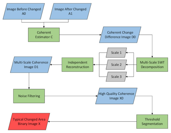
Figure 1.
Steps 1 to 4 as described in the text.
2.1. Coherence Estimators
The original variation measure of CCD is the complex-valued correlation coefficient, and the classical coherence estimator is as follows [21]:
In the estimator, x represents the pixel center point, N represents the number of pixels in the odd square window around x, i represents the i-th pixel in the observed window, A0 and A1 represent the complex-valued signal values of the image before and after the change, respectively, and * represents the complex-valued conjugate calculation. The value of C1 usually takes an absolute value, which represents the coherence estimation value of point x in the difference image.
Compared with the incoherent change detection method, the traditional coherence estimator can obtain more subtle changes and has better detection sensitivity for changes, but in the low-coherence region, it is a mixture of all of the decoherent regions. In addition to the changed areas we are interested in, some vegetation areas and low signal-to-noise ratio areas also have low coherence, resulting in a large number of false alarms, which seriously affects the detection performance. In order to solve this problem, it is necessary to improve the coherence estimator, introduce a complicated model, or add preconditions so as to distinguish the changed areas and the interference areas. Therefore, this paper uses a coherence estimator proposed in Berger [22] to replace the traditional estimator under the assumption that the variances of the two images are equal so as to obtain better change detection performance. The estimator is as follows:
Since the two SAR images before and after the changes overlap without large-scale changes, it can be assumed that the variances are approximately the same. The meaning of the parameters in C2 is the same as in C1, and when changing the product in the denominator to a sum, the resulting estimation performance is more stable. In the literature, it has been proven that C2 is better than C1 as a change metric and has a stronger capability to distinguish changed regions; in Cha’s study [13], the calculation proves that, when the coherence value is small, the mean square error of C2 is better than that of C1, the typical changed areas have a lower coherence value, and C2 has excellent detection performance and stability when detecting such areas. In this paper, the CCD method through Berger’s CCD coherence estimator is called the BCCD method. After the calculation of C2, the typical changed areas in the BCCD method show a lower coherence value than the false-alarm interference areas generated by the CCD method, which is too sensitive, so it is highlighted, but the false-alarm areas still appear as low-coherence areas, causing great interference with the detection results and affecting the extraction of the changed areas. Therefore, in order to explore the difference between the typical change areas and the false-alarm areas in the BCCD, a multi-scale analysis of the coherent change difference image was carried out, and the high- and low-frequency information of the image was observed, trying to draw a better distinction between the changed areas and the interference areas at a certain scale.
2.2. Multi-Scale Analysis
SAR images and their difference images have multi-scale characteristics in the observed world. At different scales, the change difference images present different details of changes, and the image features of different details are helpful for distinguishing the changed areas of interest; in complicated SAR image changing scenes, multi-scale analysis is very meaningful to improving the robustness and accuracy of detection. When performing multi-scale transform on the coherent change difference image calculated by the traditional CCD coherence estimator, since the region of interest and the interference region in the change region maintain similar low coherence values, they cannot be distinguished in the high- and low-frequency components of the difference image. When performing multi-scale transform on the coherent change difference image calculated by the BCCD coherence estimator, the typical changed areas exist in the low-frequency component due to its continuous variation and lower coherence value, while the interference low-coherence region is mostly the natural variation of rapid disturbance and noise, which exists in high frequency components. Through multi-scale analysis, a suitable scale is found in the BCCD difference image so that the main body of the typical changed areas is retained, and the low signal-to-noise ratio areas and the interference areas changed by their own characteristics are suppressed so that the BCCD has better detection performance.
Wavelet transform is one of the most commonly used multi-scale transform methods that can perform localized analysis on image signals [23]. Stationary wavelet transform (SWT) is a transform method based on two-dimensional discrete wavelet transform (DWT), which retains redundancy at different scales and has the characteristics of translation invariance [24]. SWT is suitable for noise elimination and modulus maximum analysis in various applications. In CCD, there are many noise areas and the maximum value is not obvious. SWT is suitable for use in CCD technology. The number of SWT scale decomposition layers N is usually 3 or 4, which can ensure that the detailed information will not be excessively lost and can reduce the detection accuracy. In CCD research, the SWT decomposition of the disparity image is performed, and its capability to automatically adapt to time and frequency takes into account the context information of the image, and it has better anti-noise performance and capability to preserve edges; most SWT methods use only low-frequency information to retain the main body, but discarding high-frequency components will lead to the loss of detailed information in the detection results, and the detection accuracy is low, so it needs to be improved. Taking three layers as an example, after the multi-scale decomposition of SWT, three layers of multi-scale difference images are obtained, and each layer contains low-frequency and horizontal, vertical, and diagonal high-frequency components corresponding to , respectively. Figure 2 is an exploded view of the SWT.
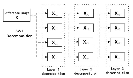
Figure 2.
SWT decomposition diagram.
After SWT multi-scale decomposition, the decomposed image needs to be reconstructed with reduced noise. The general reconstruction method only uses low-frequency components, which can achieve the effect of denoising, but the loss of edge detail information is serious. Many applications of CCD involve detecting weak traces, and such changes are generally retained in high-frequency information; in addition, SWT decomposition has redundancy, and images at different scales are correlated; for example, the high-frequency information of the next layer will be included in the low-frequency information of the previous layer. In the literature [20], an independent reconstruction method of SWT has been proposed. Taking three layers as an example, the reconstruction of the third layer in the original method only uses the low-frequency components of the third layer, and the reconstruction of the second layer is the result of independent reconstruction and the addition of all high- and low-frequency components in layer 3. The reconstruction of layer 1 is the same as that of layer 2. In this paper, the method is improved as follows. The low-frequency components of layer 2 are reconstructed using all high- and low-frequency components in layer 3 and added weights. The high-frequency information uses the same weights, and layer 1 uses all of the high-frequency components of layer 2. The reconstruction of the low-frequency components and the low-frequency components of layer 2 itself is weighted, too. Figure 3 is an improvement of the independent reconstruction diagram of the three-layer SWT.
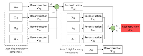
Figure 3.
Three-layer SWT independent reconstruction diagram.
The selection of the weights of each component in the independent reconstruction method in this paper is closely related to the application scenario of the CCD method, and the sum of the weights of the next layer is 1. In most change-detection applications, only low-frequency information is used to extract areas of interest. Adding high-frequency components can highlight small changes and edge details. The single-layer low-frequency information reconstruction assists with highlighting the low-frequency subject information in the changed areas. In the application scenario of this paper, in order to extract typical changed areas while preserving edge details, the weights of low-frequency components and high-frequency components are the same as 0.5, and the weight of single-layer low-frequency reconstruction layer 2 is 0. In applications that detect small changes, the weight of high-frequency components can be increased. In general, the weight of single-layer low-frequency information reconstruction can be 0, and in the application of highlighting the main body of the changed areas, it can be considered to increase its weight and reduce the weight of high-frequency components. This method as a whole retains a certain degree of freedom. The purpose of SWT independent reconstruction is to make full use of multi-scale information to enhance the image to achieve the desired difference image performance in CCD applications.
SWT decomposition and independent reconstruction are performed on the coherent difference image generated by BCCD, and a new coherent difference image is obtained, which is called the SWT-BCCD method. Using appropriate weights in the method to combine different frequency detail components can achieve the effect of removing noise and interference areas so as to extract typical changed areas in complicated scenes.
2.3. Noise Filtering
Due to its sensitivity to changes, the CCD obtains better detection performance and at the same time brings a lot of false-alarm interference. After multi-scale transform, the main body of the typical changed areas in the coherent difference image are highlighted. However, in order to preserve the edge details of the prominent areas, there is some high-frequency information in the difference image, which only reduces the false alarms, and the noise still needs to be removed. A characteristic of bilateral filtering [25] is to remove noise while preserving the edge details of the image. Because we focus on the typical changed areas, the use of bilateral filtering can remove the image noise and reduce the false-alarm interference of the image when the edge of the main body is well protected.
2.4. Threshold Segmentation
In SAR change-detection technology, the threshold-segmentation method is generally used to obtain the final binary change image. In the CCD method, the selection of the coherence threshold has a great influence on the final binary image performance. If the threshold is too high, some noise areas and interference areas will not be suppressed, and some scattered atypical changed areas will also appear in the final image; if the threshold is too low, the details of the typical changed areas will not be completely preserved and large areas will be missing. The threshold is divided into a global threshold and a local threshold in terms of calculation. Considering that the global threshold has the characteristics of fast calculation while maintaining threshold accuracy, many papers use the global threshold. Regarding the automatic global-threshold methods, the more mature ones are the OSTU [26] method, the peak–valley method, iterative threshold selection, etc. These methods are mostly selected from the peak–valley of the histogram of the difference image and the neighborhood difference, but in many complicated scenarios, it is rare for the histogram corresponding to the coherent change difference image to have single or multiple peaks and valleys when using the CCD method. Therefore, in this paper, the average value of the maximum and minimum coherence values of the difference image is the most suitable threshold for extracting typical changed areas [8]. After obtaining the binary image through threshold segmentation, we find the position where the pixel value is 1 in the image, which is the position that is judged as the typical changed areas. The performance of this method can be evaluated using a ground-truth image.
3. Experiments and Results
In order to illustrate the advantages of the multi-scale CCD method when extracting typical changed areas, two sets of SAR single-view complex-valued image (SLC) data sets are used in this paper. The first set of data (called data 1 in this paper) comes from the publicly available spaceborne SAR data of Airbus, and the location is the port near Barcelona Airport; the second set of data (called data 2 in this paper) comes from the ESAR airborne data provided by the ESA and is located outside the small town of Eggby, Sweden. This section presents the experimental results and analysis. Using the first set of data sets as experimental examples, a visual evaluation of the effect of the method is carried out, focusing on salient areas of change to validate the method. The method is then applied to the second set of data, and the overall visual and quantitative evaluation is carried out by comparing the typical changed areas annotated by humans and other algorithms, which proves the effectiveness of the algorithm in this paper.
3.1. Use of BCCD Coherence Estimator
Figure 4 is the result of using the BCCD estimator. Figure 4a,b are the images before and after the change of data 1. In order to show the advantages of the BCCD estimator and to compare it with the traditional CCD method, the images of data 1 are used to calculate the difference image using the traditional CCD coherence estimator and the BCCD method coherence estimator, respectively. In Figure 4a,b, we can see difference image calculation results by two coherence estimators. The calculation window size is 5 × 5, and the obtained coherent change difference the images are shown in Figure 4c,d, respectively. Data set 1 is a port area, including certain water areas. When rivers and sea areas are processed by CCD technology, due to their low signal-to-noise ratio and weak changes caused by water surface fluctuations, low-coherence areas will be formed, causing false-alarm interference.
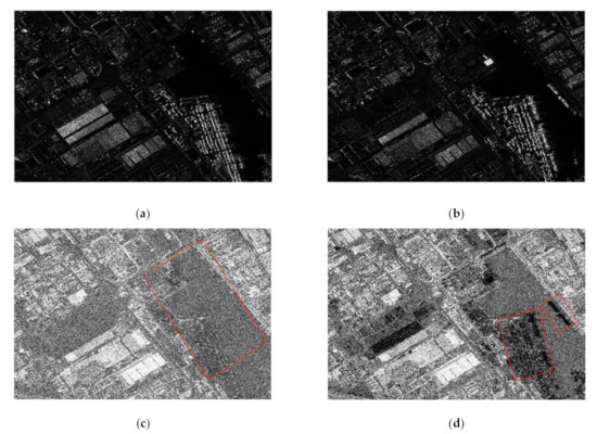
Figure 4.
Results of using the coherence estimator. (a) Image before change. (b) Image after change. (c) Traditional CCD coherence estimator results. (d) BCCD coherence estimator results.
In Figure 4c, the red box areas are water areas and a land parking lot, which are low-coherence changed areas as a whole. In the small red box in Figure 4d, we can see the water surface and the big red square in the vehicle group areas where the parking lot changes in the box. Such typical changed areas all show lower coherence values and have a certain degree of discrimination compared to Figure 4c. This shows that, after the calculation by the traditional CCD coherence estimator, the water areas are almost low-coherence areas, and the areas of interest cannot be seen. After the calculation by the BCCD coherence estimator under the assumption of equal variance, the typical changed areas in the coherent difference image no longer exhibit an approximate low coherence value with the interference region and have a lower coherence value. They are thus highlighted.
3.2. The Use of Multi-Scale SWT-BCCD Method
After being calculated by the BCCD estimator, the multi-scale SWT-BCCD method is used to better highlight the typical changed areas and eliminate the interference areas. Figure 4d, which was processed by the BCCD method, uses three-layer SWT decomposition, the wavelet basis function is Haar wavelet, and it obtains three-layer low-frequency components and horizontal, vertical, and diagonal high-frequency components. After these components are independently reconstructed, it can be seen that the main body of the change areas exist in the low-frequency component, and the interference areas exist in the high-frequency component, as is shown in Figure 5. Since the weight will affect the performance of the difference image, in the processing of data 1, in order to preserve the edge and contour information, the weight value of 0.5 is used for combined reconstruction, and the difference image obtained after processing is shown in Figure 6.
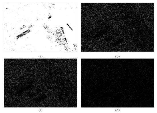
Figure 5.
Difference diagram of low-and high-frequency components. (a) Low-frequency components. (b) High-frequency horizontal components. (c) High-frequency vertical component. (d) High-frequency diagonal component.
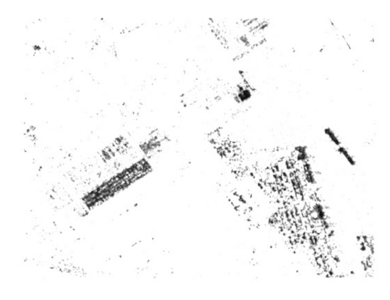
Figure 6.
Multi-scale coherent change difference image.
3.3. Noise Filtering
The difference image processed by SWT-BCCD is subjected to noise filtering, and the image is further denoised on the premise of retaining the edge and contour information of the main body by means of bilateral filtering. The overall difference diagram after noise filtering is shown in Figure 7. Compared with the original difference image, Figure 7 smooths the noise and preserves the edges and contours of the main body of the changed areas.
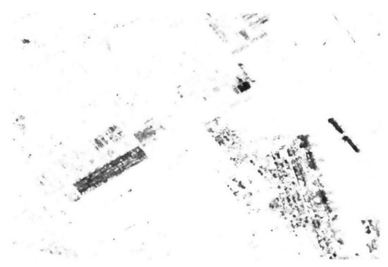
Figure 7.
Difference image after bilateral filtering.
In order to illustrate the advantages of the SWT-BCCD method in the extraction of typical changed areas, the areas near the small red box in Figure 4d are extracted for analysis, as is shown in Figure 8. Figure 8a is the traditional CCD method, which cannot obtain typical changed areas; Figure 8b is the BCCD method, which obtains a certain degree of discrimination in the coherence value; Figure 8c shows the SWT-BCCD method, which extracts the typical change areas well and removes the interference areas; Figure 8d shows that the main body is well preserved after bilateral filtering.
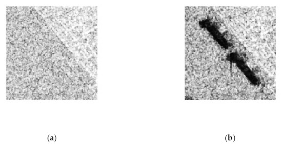
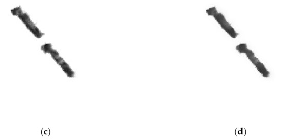
Figure 8.
Focusing on typical changed areas. (a) Traditional CCD method. (b) BCCD method. (c) SWT-BCCD method. (d) After bilateral filter processing.
3.4. Threshold Segmentation
In order to extract the typical changed areas, the change difference image needs to be binarized. The maximum and minimum coherence values of the coherent change difference image are averaged as the threshold for image segmentation. The changed areas are rendered white, and the background area is black. The binary change image is shown in Figure 9.
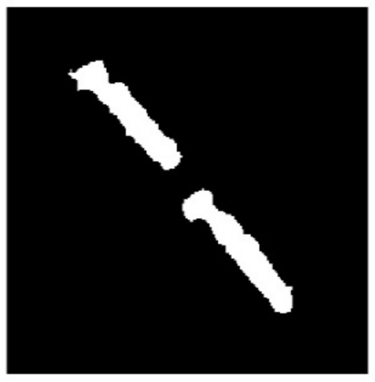
Figure 9.
Binary extraction result of typical changed areas.
Visually, it can be seen that the experiment conducted with data 1 shows that the proposed method exhibits excellent performance on the water surface disturbance areas. In order to further verify the advantages of the method in this paper, experimental analysis is performed on data 2 with more complicated scenarios, and a quantitative evaluation is carried out.
3.5. Quantitative Evaluation and Analysis of Experiment 2
In experiment 2, data 2 contain various types of ground changes, such as melting of ice and snow, soil renovation, and grass clipping. The BCCD estimator is also used in data 2, and the weight value of 1 is used for the separation of high and low frequencies in the SWT reconstruction. The scene of data 2 is more complicated, and there are more interference areas, so the effect of bilateral filtering is more obvious, and the selection of the threshold value has a greater impact on the extraction effect of typical changed areas. Data 2 and the experimental results are shown in Figure 10.
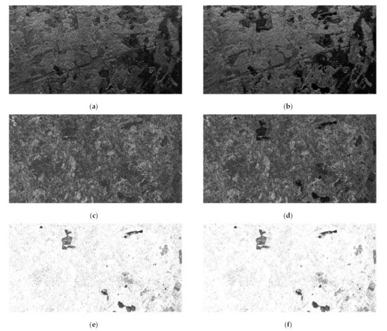
Figure 10.
The process of experiment 2. (a) Image before change. (b) Image after change. (c) Difference image of the CCD method. (d) Difference image of the BCCD method. (e) Difference image of the SWT-BCCD method. (f) Process result of bilateral filtering.
Figure 10e removes a large number of interference regions from the BCCD coherent change image and retains the typical changed areas of the subject. After bilateral filtering (Figure 10f), the change image partially removes noise globally while preserving contours.
It is well known that the non-coherent change detection method (NCCD) has a good effect when detecting typical changed areas. The method in this paper is compared with a BCCD method and NCCD method; the ground reference labels manually annotated from the optical images and the results of thresholding the three methods are shown in Figure 11. Comparing the reference label and the binary change image after threshold segmentation, the detection performance parameters of the typical changed areas are calculated. Probability correct classification (PCC), false positive (FP), overall error (OE), and kappa coefficient [27] are used as indicators to quantitatively evaluate the detection performance. PCC is used to judge the correctness of the overall change category of the method, which is equal to the sum of the number of correctly classified change samples and the number of correctly classified non-change samples divided by the total number. FP is the number of false positives divided by the total number of change samples. OE is the sum of the number of incorrectly judged as changing samples and the number of incorrectly judged as non-changed samples divided by the total number. The Kappa coefficient is a commonly used measure to measure the consistency among human evaluators [27]. It is an index that can measure the classification accuracy based on confusion matrix calculation. It comprehensively considers the detection situation of each pixel point to obtain higher accuracy. The detection performance parameters are shown in Table 1.
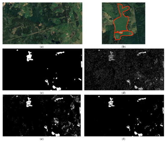
Figure 11.
The result of experiment 2. (a) Optical reference areas. (b) An example of optical reference areas labels. (c) Reference ground truth label. (d) BCCD method difference image. (e) NCCD method difference image. (f) Difference map of the SWT-BCCD method after bilateral filtering.

Table 1.
Quantitative Analysis of the Results of Experiment 2.
Through the visual comparison in Figure 11 and the quantitative calculation in Table 1, it can be seen that the SWT-BCCD method has advantages in various parameters. Although the NCCD method can have a high PCC for typical changed areas, it is limited by the threshold value when extracting the changed areas. In practical application scenarios, it is difficult to select an appropriate threshold value, and it is often only the areas where the scattering intensity changes that are detected.
In order to further illustrate the high performance of the multi-scale CCD method in this paper for extracting typical changed areas, the NCCD method, the BCCD method, and the SWT-BCCD method are compared by referring to the ground-truth labels and the receiver operating characteristic curves (ROC curve) [28] and Kappa coefficients of different threshold values. The ROC curve is the performance calculation corresponding to the selection of different thresholds. The closer to the upper left corner, the better the performance of the method. The upper left corner has a higher detection probability and a lower false-alarm probability. Figure 12 shows the ROC curves and Kappa coefficient curves for the three methods. From Figure 12a’s ROC curve, it can be concluded that the curve of the method in this paper is closer to the upper left corner and has better performance; at the same time, in Figure 12b, the kappa coefficient diagram, although the NCCD method and the SWT-BCCD method have the best performance, the optimal Kappa coefficients are similar, but in the actual detection situation, it is difficult for the NCCD method to use the optimal threshold for segmentation. Therefore, the above analysis verifies that the multi-scale CCD method proposed in this paper is effective and robust for improving the detection rate of typical changed areas, resisting low-coherence interference and reducing the probability of false alarms.
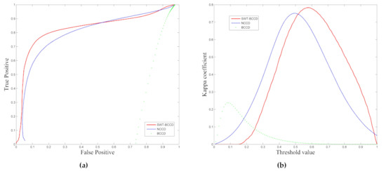
Figure 12.
Analysis of indicators of various methods. (a) ROC curve. (b) Kappa coefficient of different threshold values.
4. Discussion
In SAR image change detection applications, in addition to incoherent change detection based on image amplitudes, having a coherent change detection method that can use phase information is a more sensitive technique to detect invisible and undetectable areas of an amplitude image. It can play an important role in many small change scenarios and also has good detection performance in typical changed areas. The biggest challenge facing the CCD method is the large number of false alarms caused by its extremely high sensitivity. Most CCD algorithms hope to obtain more pre-information through data of different dimensions to reduce the probability of false alarms. Such data are usually difficult to obtain. Therefore, it is a good idea to optimize the CCD method using some image processing methods to mine the data in a single dimension to obtain the changed areas of interest.
The algorithm in this paper aims to use the multi-scale analysis method to separate the typical changed areas from the false-alarm areas in the coherent change difference image detected by the CCD at a certain scale. This is achieved using a coherence estimator with an equal variance assumption that is different from the traditional CCD and then combining the multi-scale characteristic images using an independently reconstructed SWT method. In order to achieve better performance, the overall image is also smoothed. Changes to the coherence estimator are the basis of the algorithm, and the equal variance assumption estimator can allow typical changed areas to have lower coherence values, which can be distinguished from interference region. After multi-scale transform, it can be clearly found that the typical changed areas are located on the low-frequency component and that the interference areas are located on the high-frequency component. They can be separated during reconstruction so as to achieve the purpose of extracting the typical changed areas in some application scenarios of CCD. At this time, due to the independent reconstruction method used in multi-scale reconstruction, the weights can be adjusted and combined, the small traces are retained, and the difference between the typical changed areas and the false-alarm interference areas have increased contrast between them. In terms of noise filtering, the algorithm in this paper chooses to filter the image as a whole under the premise of optimizing the calculation speed. In some application scenarios, the local filtering of the image can be considered. In terms of threshold selection, different from the incoherent method, the coherent change difference image obtained by the algorithm in this paper will exclude areas with only a small amount of image brightness change and will not change the classification of a large number of areas due to a small change in the threshold.
5. Conclusions
This paper introduces a multi-scale analysis-based CCD method for extracting typical changed areas. The algorithm includes a coherence estimator, multi-scale transform, noise filtering, and threshold selection. The results show that the typical changed areas after passing through the coherence estimator under the assumption of equal variance has a lower coherence value and can be separated from the interference region after multi-scale transform. After noise filtering, typical changed areas extracted by threshold segmentation have excellent detection performance parameters. By drawing the ROC curve and the kappa coefficient curve, we found that the method is effective and correct.
The BCCD estimator is the basis of the method in this paper. With the development of CCD technology, more advanced estimators gradually appear, and other estimators will be tried in future research. The size of the weight of each component in the independent reconstruction of SWT depends on the application scenario of the CCD method, which is relatively broad. To date, there have been some studies discussing the coherence values of various types of regions in the CCD method scene, and the selection of weights can be refined according to this. In terms of noise filtering, the bilateral filtering method filters the entire image, and subsequent research can consider more careful filtering methods to further remove noise while preserving the edge of the changed areas. In terms of threshold selection, many CCD methods can use the mean value of the coherence value as the threshold, but this is not absolute and it may not be effective in some CCD applications and needs to be adjusted according to specific conditions.
The method proposed in this paper has a good detection effect on typical changed areas, such as target detection, ship trajectory detection, and other applications and can efficiently extract interesting changed areas. This method can also be combined with commonly used NCCD change detection methods to improve the overall detection performance. This method also maintains a certain degree of freedom, which can maintain the high-sensitivity advantage of the CCD itself.
This paper conducts experiments on complicated scene data, and the results verify the effectiveness of the method proposed in this paper. The processed data contain rich types of changes in ground objects, which proves that the method proposed in this paper has a certain universality and is valuable for other CCD application scenarios.
Author Contributions
Conceptualization, Z.W.; methodology, Z.W.; software, Z.W.; validation, Z.W.; formal analysis, Z.W.; investigation, Z.W. and S.L.; resources, Z.W. and J.W.; writing—original draft preparation, Z.W. and J.W.; writing—review and editing, Z.W. and S.L.; visualization, Z.W.; supervision, S.L.; project administration, S.L. and J.W.; funding acquisition, J.W. All authors have read and agreed to the published version of the manuscript.
Funding
This work was supported by the National Natural Science Funds under Grant 62001451 and the Civil Aerospace Technology Advance Research Program D040114.
Institutional Review Board Statement
Not applicable.
Informed Consent Statement
Not applicable.
Data Availability Statement
Publicly available datasets were analyzed in this study. These data can be found here: [BioSAR (2007) campaign-Earth Online (esa.int)].
Acknowledgments
Thanks to everyone who contributed to this article, and thank you for spending your precious time and energy providing support and advice on this article.
Conflicts of Interest
The authors declare no conflict of interest.
References
- Moreira, A.; Prats-Iraola, P.; Younis, M.; Krieger, G.; Hajnsek, I.; Papathanassiou, K.P. A tutorial on synthetic aperture radar. IEEE Geosci. Remote Sens. Mag. 2013, 1, 6–43. [Google Scholar] [CrossRef]
- Hu, Z.; Bryant, M.; Qiu, R.C. Multi-path SAR change detection. In Proceedings of the 2012 IEEE Radar Conference, Atlanta, GA, USA, 7–11 May 2012; pp. 859–863. [Google Scholar] [CrossRef]
- Singh, A. Review article digital change detection techniques using remotely-sensed data. Int. J. Remote Sens. 1989, 10, 989–1003. [Google Scholar] [CrossRef]
- Preiss, M.; Stacy, N.J.S. Coherent Change Detection: Theoretical Description and Experimental Results; Defence Science and Technology Organisation: Edinburgh, SA, Australia, 2006. [Google Scholar]
- Jung, J.; Kim, D.; Lavalle, M.; Yun, S.H. Coherent change detection using InSAR temporal decorrelation model: A case study for volcanic ash detection. IEEE Trans. Geosci. Remote Sens. 2016, 54, 5765–5775. [Google Scholar] [CrossRef]
- Tzouvaras, M.; Danezis, C.; Hadjimitsis, D.G. Small Scale Landslide Detection Using Sentinel-1 Interferometric SAR Coherence. Remote Sens. 2020, 12, 1560. [Google Scholar] [CrossRef]
- Wang, Z.; Wang, Y.; Wang, B.; Hu, X.; Song, C.; Xiang, M. Human Activity Detection Based on Multipass Airborne InSAR Coherence Matrix. IEEE Geosc. Remote Sens. Lett. 2021, 19, 1–5. [Google Scholar] [CrossRef]
- Hammer, H.; Kuny, S.; Thiele, A. Enhancing Coherence Images for Coherent Change Detection: An Example on Vehicle Tracks in Airborne SAR Images. Remote Sens. 2021, 13, 5010. [Google Scholar] [CrossRef]
- Liao, M.; Jiang, L.; Lin, H.; Huang, B.; Gong, J. Urban change detection based on coherence and intensity characteristics of SAR imagery. Photogramm. Eng. Remote Sens. 2008, 74, 999–1006. [Google Scholar] [CrossRef]
- Engdahl, M.E.; Borgeaud, M.; Rast, M. The use of ers-1/2 tandem interferometric coherence in the estimation of agricultural crop heights. IEEE Trans. Geosci. Remote Sens. 2002, 39, 1799–1806. [Google Scholar] [CrossRef]
- Manzoni, M.; Monti-Guarnieri, A.; Molinari, M.E. Joint exploitation of spaceborne SAR images and GIS techniques for urban coherent change detection. Remote Sens. Environ. 2021, 253, 112152. [Google Scholar] [CrossRef]
- Wang, Z.; Wang, Y.; Wang, B.; Xiang, M.; Wang, R.; Xu, W.; Song, C. Multi-Frequency Interferometric Coherence Characteristics Analysis of Typical Objects for Coherent Change Detection. Remote Sens. 2022, 14, 1689. [Google Scholar] [CrossRef]
- Cha, M.; Phillips, R.D.; Wolfe, P.J.; Richmond, C.D. Two-stage change detection for synthetic aperture radar. IEEE Trans. Geosci. Remote Sens. 2015, 53, 6547–6560. [Google Scholar] [CrossRef]
- Wahl, D.E.; Yocky, D.A.; Jakowatz, C.V.; Simonson, K.M. A new maximum-likelihood change estimator for two-pass SAR coherent change detection. IEEE Trans. Geosci. Remote Sens. 2016, 54, 2460–2469. [Google Scholar] [CrossRef]
- Bouaraba, A.; Belhadj-Aissa, A.; Closson, D. Man-made change detection using high-resolution Cosmo-Skymed SAR interferometry. Arab. J. Sci. Eng. 2016, 41, 201–208. [Google Scholar] [CrossRef]
- Andre, D.; Morrison, K.; Blacknell, D.; Muff, D.; Nottingham, M.; Stevenson, C. Very high resolution coherent change detection. In Proceedings of the 2015 IEEE Radar Conference (RadarCon), Arlington, VA, USA, 10–15 May 2015; pp. 634–639. [Google Scholar] [CrossRef]
- Barber, J.; Kogon, S. Probabilistic three-pass SAR coherent change detection. In Proceedings of the 2012 Conference Record of the Forty Sixth Asilomar Conference on Signals, Systems and Computers (ASILOMAR), Pacific Grove, CA, USA, 4–7 November 2012; pp. 1723–1726. [Google Scholar] [CrossRef]
- Deren, L.I. Change detection from remote sensing images. Geomat. Inf. Sci. Wuhan Univ. 2003, 28, 7–11. [Google Scholar]
- Xu, Y.; Yang, C.; Sun, B.; Yan, X.; Chen, M. A novel multi-scale fusion framework for detail-preserving low-light image enhancement. Inf. Sci. 2021, 548, 378–397. [Google Scholar] [CrossRef]
- Quan, S.N.; Cui, Y.; Xiong, B.L.; Kuang, G.Y. Employing Multi-scale Fusion for SAR Image Change Detection. J. Signal Process. 2016, 32, 4. [Google Scholar]
- Catelli, F.; Guarnieri, A.M.; Prati, C. Coherence estimation of interferometric SAR images. In Proceedings of the 1996 8th European Signal Processing Conference (EUSIPCO 1996), Trieste, Italy, 10–13 September 1996; pp. 1–4. Available online: https://ieeexplore.ieee.org/abstract/document/7083185 (accessed on 27 April 2015).
- Berger, T. On the correlation coefficient of a bivariate, equal variance, complex Gaussian sample. Ann. Math. Stat. 1972, 43, 2000–2003. [Google Scholar] [CrossRef]
- Gao, J.; Wang, B.; Wang, Z.; Wang, Y.; Kong, F. A wavelet transform-based image segmentation method. Optik 2020, 208, 164123. [Google Scholar] [CrossRef]
- Kumar, A.; Tomar, H.; Mehla, V.K.; Komaragiri, R.; Kumar, M. Stationary wavelet transform based ECG signal denoising method. ISA Trans. 2021, 114, 251–262. [Google Scholar] [CrossRef] [PubMed]
- Tomasi, C.; Manduchi, R. Bilateral filtering for gray and color images. In Proceedings of the Sixth International Conference on Computer Vision (IEEE Cat. No. 98CH36271), Bombay, India, 7 January 1998; pp. 839–846. [Google Scholar] [CrossRef]
- Otsu, N. A Threshold Selection Method from Gray-Level Histograms. IEEE Trans. Syst. Man Cybern. 1979, 9, 62–66. [Google Scholar] [CrossRef]
- Wan, T.; Jun, H.U.; Zhang, H.; Pan, W.U.; Hua, H.E. Kappa coefficient: A popular measure of rater agreement. Shanghai Arch. Psychiatry 2015, 27, 62. [Google Scholar]
- Mandrekar, J.N. Receiver operating characteristic curve in diagnostic test assessment. J. Thorac. Oncol. 2010, 5, 1315–1316. [Google Scholar] [CrossRef] [PubMed]
Publisher’s Note: MDPI stays neutral with regard to jurisdictional claims in published maps and institutional affiliations. |
© 2022 by the authors. Licensee MDPI, Basel, Switzerland. This article is an open access article distributed under the terms and conditions of the Creative Commons Attribution (CC BY) license (https://creativecommons.org/licenses/by/4.0/).