Technical Note

A Simple Procedure to Preprocess and Ingest Level-2 Ocean Color Data into Google Earth Engine

by
Elígio de Raús Maúre
1,*,
Simon Ilyushchenko
2 and
Genki Terauchi
1
1
Northwest Pacific Region Environmental Cooperation Center, Toyama 930-0856, Japan
2
Google LLC, 1600 Amphitheater Parkway, Mountain View, CA 94043, USA
*
Author to whom correspondence should be addressed.
Remote Sens. 2022, 14(19), 4906; https://doi.org/10.3390/rs14194906
Submission received: 26 August 2022 / Revised: 23 September 2022 / Accepted: 27 September 2022 / Published: 30 September 2022
(This article belongs to the Section Ocean Remote Sensing)

Abstract

:
Data from ocean color (OC) remote sensing are considered a cost-effective tool for the study of biogeochemical processes globally. Satellite-derived chlorophyll, for instance, is considered an essential climate variable since it is helpful in detecting climate change impacts. Google Earth Engine (GEE) is a planetary scale tool for remote sensing data analysis. Along with OC data, such tools allow an unprecedented spatial and temporal scale analysis of water quality monitoring in a way that has never been done before. Although OC data have been routinely collected at medium (~1 km) and more recently at higher (~250 m) spatial resolution, only coarse resolution (≥4 km) data are available in GEE, making them unattractive for applications in the coastal regions. Data reprojection is needed prior to making OC data readily available in the GEE. In this paper, we introduce a simple but practical procedure to reproject and ingest OC data into GEE at their native resolution. The procedure is applicable to OC swath (Level-2) data and is easily adaptable to higher-level products. The results showed consistent distributions between swath and reprojected data, building confidence in the introduced framework. The study aims to start a discussion on making OC data at native resolution readily available in GEE.

Graphical Abstract

1. Introduction

Satellite observations of ocean color (OC) opened a new window for an unprecedented monitoring of water quality over spatial and temporal scales not feasible with in-situ sampling. While OC data have been collected at medium resolution (~1 km) and in some cases higher resolution (~300 m), global datasets are only available at coarse resolutions (~4 km), limiting the potential benefits that coastal water managers could obtain from the data. In recent years, the number of higher (<1 km) resolution OC sensors has been increasing [1]. Nevertheless, global maps of geophysical parameters of interest for water quality monitoring, e.g., chlorophyll concentration, remain at the traditional 4 km spatial resolution [2]. Studies interested in the study of coastal phenomena, such as red tides, harmful algal blooms, or eutrophication, have always opted to use Level-2 data [2,3,4,5] and in some cases even lower-level data [6], which requires high technical expertise. Since the application of OC data in water quality monitoring is an emerging field, most practitioners lack the skills to handle these datasets. These difficulties, along with the ever-increasing data volume, pose additional challenges in terms of data access and processing [7], not to mention that different data providers have different data access requirements. To address such challenges, a paradigm shift has emerged and cloud computing appears as a new norm for on-demand data analysis [8].
Google Earth Engine (GEE), a cloud computing platform with petabytes of remote sensing data and optimized for planetary scale analysis powered by Google cloud computing [9], is increasingly contributing to the application of remote sensing for environmental monitoring in various fields [10,11]. Land-based studies and applications of remote sensing data have achieved tremendous progress in recent years by taking advantage of the availability, for instance, of historical Landsat collections in the GEE to map and monitor forest cover change, among others [11,12,13,14,15,16]. Similarly, studies leveraging the use of high-resolution data for coastal ocean research are benefiting from the availability of Landsat and Sentinel archives in GEE. Mora-Soto et al. [17], for instance, produced a GEE-based global map of giant kelp and intertidal green algae with high-resolution Sentinel-2 Imagery. Chen et al. [18] mapped the spatiotemporal changes in salt marshes in the intertidal zone of China with Landsat 5/8 and Sentinel-2 imagery. Among geographic information system tools, GEE is an attractive tool for remote sensing data applications, in part, due to its scalability and ease-of-use, the capacity to quickly share analysis-ready maps with a simple link, and the possibility of publishing powerful dynamic web-applications. GEE has contributed to advances in the application of remote sensing data to science and decision making by greatly reducing the time and effort needed to work with large remote sensing datasets. Although the applications and potentials of GEE grow by the day, to date, the lack of OC data at native resolution remains a big deterrence to applying GEE in OC related studies. OC data products from legacy (e.g., MODIS) sensors are often unsatisfactory for coastal ocean research due to low spatial (e.g., 1 km) resolution or inadequate atmospheric correction (e.g., negligible near-infrared signals) in optically complex and heterogeneous coastal water bodies [19]. However, even for open ocean research, GEE has also not been widely utilized (so far) by the ocean color community, despite the benefits for its processing of large-scale datasets.
To address the challenge of having Level-2 OC data in the GEE, this study introduces a simple procedure for the preprocessing and ingestion of OC data. The results of our analysis suggest that Level-2 OC geophysical parameters at their native spatiotemporal resolution and associated quality flag information can be remapped (reprojected) and ingested into GEE while retaining the source data statistical characteristics. Since GEE can handle any dataset at native resolution at the global scale, the significance would be unparalleled. Studies focusing on algorithm development, OC data performance evaluation with in situ data, eutrophication, and red-tides monitoring, just to name a few, would benefit immensely. This would significantly contribute to calls for the application of Earth observations in support of sustainable developments goals and the United Nations decade of ocean science for sustainable development. This paper should encourage different OC users and data providers to preprocess and ingest OC data at native resolution into the GEE to support their application in studies of coastal water phenomena and global change.

2. Materials and Methods

2.1. Satellite Data

Level-2 OC imagery from the Moderate Resolution Imaging Spectroradiometer (MODIS) aboard Aqua satellite with a spatial resolution of 1 km, reprocessing 2018 (https://oceancolor.gsfc.nasa.gov/reprocessing/r2018/aqua/, accessed on 17 July 2022), was used to demonstrate the procedure followed in preprocessing and ingesting Level-2 data into the GEE. The U.S. National Aeronautics and Space Administration (NASA) Ocean Biology Processing Group (OBDG) disseminates its Level-2 data in Network Common Data Form 4 (netCDF4) file format. Each Level-2 file contains geophysical values for each pixel, derived from the Level-1 radiance by applying sensor calibration (for Level-1A), atmospheric corrections, and geophysical parameter algorithms. The contents of the Level-2 file are organized in (i) Global Attributes, (ii) Dimensions (Data Structure), and (iii) Groups. The groups contain (a) Sensor Band Parameters, (b) Scan-Line Attributes, (c) Geophysical Data, (d) Navigation Data, and (e) Processing Control. In our data ingestion procedure, we focus on (c) Geophysical Data while other information, such as (b) and (d), was only used during the reprojection phase. Detailed description of the contents in the netCDF4 file can be found at https://oceancolor.gsfc.nasa.gov/docs/format/l2nc/, accessed on 17 August 2022.
MODIS/Aqua has the longest data record in the history of OC observations spanning a period of 20 years from 4 July 2002 to present, well beyond its design life of 6 years. This sensor measures spectral radiance at 36 bands with bands 8–16 dedicated to OC, phytoplankton, and biogeochemistry (https://modis.gsfc.nasa.gov/about/specifications.php, accessed on 12 July 2022). It has contributed immensely to studies of marine ecosystems variability and change, to monitoring coastal eutrophication, and in assisting policy making for the protection of our environment [2,20,21,22]. Although MODIS/Aqua continues to collect valuable data, with its aging, it may reach the end of life at any time. Meanwhile, new OC sensors with enhanced spatial and temporal resolutions were launched. One such example is the Second-generation GLobal Imager (SGLI) aboard the Global Change Observation Mission–Climate (GCOM-C, Shikisai) satellite of the Japan Aerospace eXploration Agency (JAXA) launched in December 2017 (https://shikisai.jaxa.jp/index_en.html, accessed on 13 July 2022). The Shikisai, with its higher spatial resolution of 250 m, is expected to enhance the study of coastal processes [23]. The other example is the first Geostationary Ocean Color Imager (GOCI) instrument launched in June 2010. GOCI, with its hourly images, effectively allows the study of short-term variability of coastal water phenomena, such as red tides [3,24]. This paper provides data ingestion examples for MODIS/Aqua (R2018) and SGLI/GCOM-C (version 3, https://suzaku.eorc.jaxa.jp/GCOM_C/data/product_std.html, accessed on 13 July 2022) Level-2 OC products. The OBPG disseminates OC data from space agencies other than NASA, such as MERIS (Medium Resolution Imaging Spectrometer) data from the European Space Agency or GOCI data from Korea Ocean Satellite Center. Since all Level-2 data disseminated by the Ocean Biology Data Active Archive Center (OB.DAAC, https://oceancolor.gsfc.nasa.gov/, accessed on 23 August 2022) have a consistent data structure, i.e., the same netCDF4 file format, the extension of our procedure to other sensors should be easy and straightforward.
Unlike MODIS/Aqua, Geophysical Data from the Shikisai are disseminated in two separate files: one for in-water properties (IWPR) and the other for normalized water leaving radiance (NWLR). The IWPR file contains derived chlorophyll-a concentration, absorption coefficient by colored dissolved organic matter (CDOM), and the concentration of total suspended matter (TSM). Remote sensing reflectance is derived from the NWLR file. The Shikisai data are disseminated in Hierarchical Data Format Version 5 (HDF5). Similar to netCDF4, the contents of the HDF5 are organized in groups with (i) Geometry Data (equivalent to (d) of netCDF4), (ii) Global Attributes, (iii) Image Data (equivalent to (c)), (iv) Level-1 Attributes, and (v) Processing Attributes. The data files used in this demonstration are listed in Table 1.
MODIS/Aqua data on 5 May 2022 were retrieved from NASA’s OB.DAAC. The Shikisai data on 3 May 2022 were retrieved from the JAXA’s Global Portal System (G-Portal, https://gportal.jaxa.jp, accessed on 17 July 2022). Both data are freely available from the respective data portals upon registration.

2.2. Data Ingestion Workflow

2.2.1. Swath Reprojection

The steps for the Level-2 OC data reprojection up until data ingestion into GEE are summarized in Figure 1. The first step begins with data retrieval from the providers, followed by the reprojection (remapping) of Level-2 imagery. The data is reprojected into a target map projection with a regularly spaced grid. Level-2 data is in the shape defined by the satellite field of view representing the portion of the surface observed by the sensor as it revolves around the Earth. These Level-2 images are often called "swaths". They represent 2-dimensional (2D) grids of the portion of Earth seen by the satellite sensor and arranged in x-y coordinates representing, respectively, the pixels per line (the field of view) and number of lines along the flight path. Such datasets, while gridded, are not projected onto a regular grid, that is, they are non-uniformly spaced. It, therefore, is impossible to ingest such data into the GEE directly. Pyresample, a Python package for the resampling of swath dataset into a grid, or a grid into a swath, or a swath to another swath, was used to remap swath data using the nearest neighbor (NN) method (https://pyresample.readthedocs.io/en/latest/, accessed on 18 July 2022). The NN is located using a fast KD-tree algorithm provided by the pykdtree library. KDTree is short for k-dimensional tree, a space-partitioning data structure for organizing points in a k-dimensional space [25] (in the case of swath data, a 2-dimensional tree). Pyresample uses 1 neighbor in its NN query. This is appropriate for our resampling objective, since Level-2 quality flag information can be effectively transferred to the target geolocation point without noise, something that would be very challenging if NN > 1 were used. In the query for NN, one has to supply the region of influence, which Pyresample uses as a cutoff distance from the target pixel center. As we will show later in Section 3, we choose a value twice that of the spatial resolution (2R) to compensate for the decrease in resolution as one moves away from the swath center. Since the NN will return only neighbors within the cutoff distance, some pixels toward the swath edge may not have a neighbor if the actual spatial resolution is used. This results from the fact that the pixels at the swath edge are significantly larger than their counterparts at the center. Please note that the 2R distance corresponds to the upper limit for the search algorithm. The actual NN may be located at distance d << R (Figure A1, Appendix A).
All bands of either (c) the netCDF4 file or (iii) the HDF5 file can be passed at once into Pyresample as stacked 2D arrays. During reprojection, Pyresample requires two geolocation inputs: one for the swath (source geolocation) and the other for the target map. Source geolocation was derived from the swath navigation data or geometry data depending on whether the file was netCDF4 or HDF5. The target geolocation was created using Pyresample geometry helper functions. To create a new target geographic area of regularly spaced pixels, Pyresample required a pre-defined projection information, area extent, spatial resolution, height and width, and other relevant information of the target area. The projection and area extent were created with the help of pyproj, a Python interface to PROJ (cartographic projections and coordinate transformations library, https://pyproj4.github.io/pyproj/stable/index.html, accessed on 14 July 2022). We choose the LAEA (Lambert azimuthal equal-area projection) since it preserves the pixel area across the domain of the target map projection. This projection is a good choice, for instance, in ocean color data applications, such as in primary productivity due to its flux-preserving nature.
We used Level-2 swath imagery that intersected our area of interest, the Northwest Pacific region (115–155 E, 20–60 N). However, for the reprojected swath, the area extent was defined by the geolocation boundaries of the input swath. We extracted the center longitude and latitude of the swath and used it to initialize the projection in pyproj. The center longitude and latitude can be obtained, for example, from the Scan-Line Attributes in the netCDF4 file. Since the swath images contain the information of the center longitude/latitude, the center of the target projection would be located halfway across the scan direction (number of lines). After the projection is initialized, geolocation bounds of the swath are translated into corresponding values of the target projection (Figure A2, Appendix A). Using the MODIS/Aqua file (Table 1), in Figure A2, we provide a Python code snippet of the projection definition and translation of swath bounds. Bounds were obtained from the Global Attributes and the center longitude and latitude from the Scan-Line Attributes as mentioned above. Since the HDF5 file does not contain information of the center scan line, we estimated this information based on the great circle distance and using the swath boundary longitude and latitude data. When the same approach was applied to MODIS/Aqua, the results were consistent with the information given in the netCDF4 file. Transformations between latitude/longitude and the LAEA projection are nonlinear. As such, the bounds obtained in Figure A2 do not cover the entire swath in the target map. For that reason, transform_bounds() provides the required transformations that account for the nonlinearities and returns the outermost bounds (cf. code snippet in Figure A3).
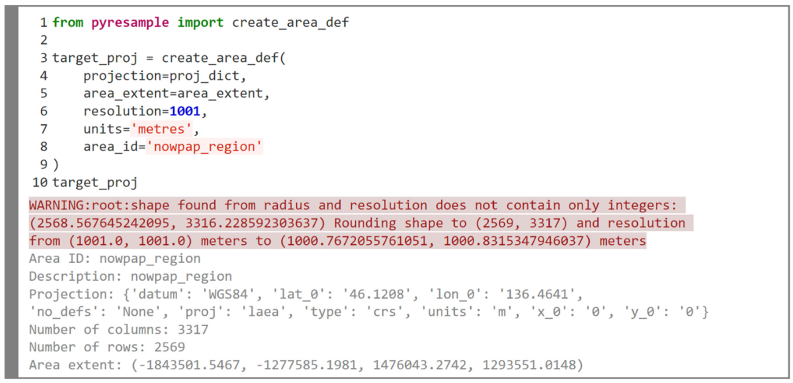
After the bounds are defined in the same units as the projection, the target area was created using Pyresample’s create_area_def() function (Figure A4). Note that the nominal spatial resolution of MODIS/Aqua is 1 km or 1000 m as indicated in the file attributes. However, 1001 m was passed to Pyresample. In the case of SGLI/GCOM-C with 250 m, 251 m was passed. This ensured that the adjusted pixel resolution of the target projection did not return smaller than nominal resolution. Internally, Pyresample determines the spatial resolution based on the height and width of the target projection. Since we did not provide such information, Pyresample obtains the height (rows) and width (columns) from the area extent and the provided spatial resolution. If the shape is already known, it can also be passed to Pyresample; however, the resolution will then be adjusted accordingly. We could also estimate the shape of the target projection using the pixel resolution of 1 km (1000.90 m) of the Equal-Area Scalable Earth (EASE) grid projections (https://nsidc.org/ease/ease-grid-projection-gt, accessed on 24 July 2022). Nevertheless, the resulting resolution obtained by using the above procedure was similar.

2.2.2. Output Result

The remapped swaths by Pyresample’s NN method were then, in step 2, saved in GeoTIFF file format. Geospatial Data Abstraction Library (GDAL, https://gdal.org/, accessed on 15 July 2022) was used to create the GeoTIFF file and the metadata of this file were copied from the source netCDF4 or HDF5 file. The copied metadata are those of the Global Attributes and attributes of each variable with the exception of geolocation information. Unlike the netCDF4 file, GeoTIFF file does not allow a mixture of data types, that is, a mix of integers and floating-point numbers in different bands. In the netCDF4 file, geophysical parameters are saved as integers except for chlorophyll data, which are saved as a floating-point number. In the case of the HDF5 file Image Data parameters are saved as integers. Since bit-shifting operations are not supported on floating-point numbers, all data were scaled and saved as 4-byte signed integers (int32). This was performed for consistency with the Level-2 quality flag information of NASA OC files. The chlorophyll data were scaled into integers by subtracting an offset of 0.001 [mg m–3] and dividing by the scale factor of 1e-6, Equation (1). Integers have also the advantage of being easily compressed.
scaled_data = (data − offset)/scale_factor

2.2.3. GEE Pre-Ingestion Step: Cloud Bucket and Manifest File

Prior to the upload and ingestion of the created GeoTIFF into GEE, it is important to verify that all geolocation tags are correctly written in the file (Figure A5). GDAL provides methods to translate the GeoTIFF (gdal_translate) into a correctly geolocated image. Moreover, before the translation, we can run a GDAL utility (gdaladdo) to build overviews so that the created file becomes Cloud Optimized GeoTIFF (COG, https://gdal.org/drivers/raster/cog.html#raster-cog, accessed on 17 August 2022). COG is a regular GeoTIFF but with added pyramid overviews, which help with the efficiency of workflows in the cloud. GEE is able to read or load these COGs without ingestion, directly from the Google Cloud storage (https://developers.google.com/earth-engine/Earth_Engine_asset_from_cloud_geotiff, accessed on 21 July 2022). However, for files being ingested into GEE, it is not worth creating COG files since GEE does not currently make use of the overviews. The COG component will be simply ignored, and GEE will create its own COG on the fly. It is also worth noting that gdal_translate can write COGs directly to the output file (https://gdal.org/drivers/raster/cog.html, accessed on 17 August 2022).
After the GeoTIFF file is translated, it can be uploaded into GEE directly through Code Editor or through Google Cloud bucket using the gsutil tool (https://cloud.google.com/storage/docs/gsutil, accessed on 4 August 2022) followed by issuing an Earth Engine (EE) upload command in the EE command-line tool. If one is ingesting more than a dozen images, ingestion through Google Cloud bucket is preferred over manual ingestion through Code Editor (https://developers.google.com/earth-engine/guides/image_upload, accessed on 18 July 2022) which becomes quickly overwhelming. Note that with a cloud bucket the ingestion process can be automated although bucket charges will be incurred.
After uploading the GeoTIFF into a cloud bucket, a JSON (JavaScript Object Notation, https://docs.python.org/3/library/json.html, accessed on 15 July 2022) manifest file needs to be created. The structure of the JSON file, although complex, gives more flexibility to the user during the ingestion process. For instance, a multiband GeoTIFF can be uploaded along with its per-band names, something not feasible with the Code Editor. Additionally, multiple source files can be combined (mosaiced) into a single image; separate files representing different bands can be ingested into a multiband image. Further details can be found at https://developers.google.com/earth-engine/guides/image_manifest, accessed on 9 August 2022. The manifest file should, at least, contain the target asset ID (the name where the image will be uploaded to) and the cloud bucket address where the GeoTIFF file resides in the Google Cloud. Furthermore, global attributes, per-band attributes, and other relevant metadata can also be appended. A sample code for creating the JSON manifest file using the example images is included in our GitHub repository (https://github.com/npec/ee-oc-data-ingestion).

2.2.4. Ingestion of the GeoTIFF into GEE

The final step is simply to upload the processed GeoTIFF into the GEE. This is achieved using the EE Python API (https://developers.google.com/earth-engine/tutorials/community/intro-to-python-api, 15 July 2022). As mentioned above, the GeoTIFF file is first uploaded to Google cloud bucket using gsutil. A JSON manifest file with the GeoTIFF cloud location, the associated metadata, and the target asset ID is then created. This JSON manifest file is then passed to the EE Python API command line tool to perform the ingestion. While creating the JSON manifest file we can also indicate the pyramiding policy to be used by the GEE when generating the COG file. Options for the pyramiding policy include “MEAN” (default), “MODE”, and “SAMPLE”. GEE documentation recommends using “SAMPLE” where “MEAN” or “MODE” does not make sense as in the case of quality flag information (https://developers.google.com/earth-engine/guides/image_manifest, accessed on 9 August 2022).
In summary, we obtained the swath image from the space agency’s data archive, reprojected the swath using Pyresample, and saved the results in GeoTIFF file. The GeoTIFF was then sent to a Google Cloud bucket and subsequently ingested into the GEE using a JSON manifest file through EE Python API. The full implementation of the above steps can be found at https://github.com/npec/ee-oc-data-ingestion of our GitHub repository.

3. Results

We describe the results obtained using the above detailed steps. We compared the swath with the remapped data within a subset area. The subset area was obtained using a polygon defined by the swath geolocation data. After the swath was remapped, the statistics of the pixels falling within this polygon were compared with the original swath data. The results are detailed below.

3.1. Mapped Imagery and the Radius of Influence

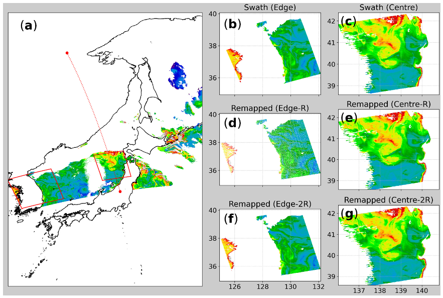
We first compared the impact of the radius of influence (cutoff distance) on remapped imagery. We tested two values, one equal to the nominal spatial resolution (R) and the other twice the spatial resolution (2R, Figure 2). With a cutoff of R, salt-and-pepper-like noise increases as we move toward the swath edge. The size of the pixels increases significantly toward the swath edge so that no NN pixels fall within the distance R. However, with a cutoff of 2R, this scenario is reversed, and the remapped result now looks as smooth as the input swath data. It is worth noting that the 2R cutoff adopted will not entirely solve this issue since the pixel size in the across-track direction (horizontal direction from center) becomes four times larger than that at the sub-satellite point (nadir view). In the case of data near the swath center, this effect is not observed since the resolution of both swath and projected grid are almost the same (1:1 correspondence, Figure A1). Consequently, for the mapping procedure introduced here, the adopted cutoff value is equal to 2R. Doing so, we minimize significant data gaps introduced by the decrease in resolution toward the swath edge.
In the case of SGLI/GCOM-C, although the same 2R was used, the difference in using R or 2R was much smaller even near the swath edge. MODIS/Aqua has a swath width of about 2330 km, which is about 50% wider than that of SGLI/GCOM-C (1150 km). Additionally, at the swath edge, the along-track resolution of SGLI/GCOM-C remains consistent to that of the sub-satellite view, and only the across-track becomes twice as big. In contrast, for MODIS/Aqua, both along and across track pixel sizes become, respectively, twice and four times as large (Figure A1 in Appendix A).

3.2. Verification of the Remapped Results

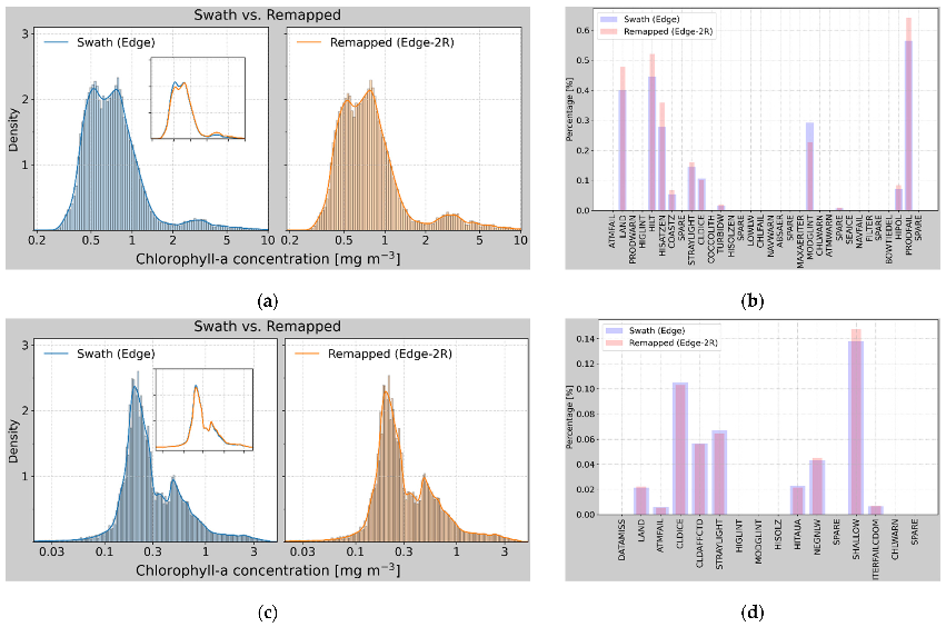
We verified the results by examining the probability density of the original swath versus that of reprojected data (Figure 3). We used data from polygons at the swath edge (see red box in Figure 2 and Figure A6) where pixel distortions are relatively large. The results remained consistent between the original swath and the remapped data. This was expected, since the NN method simply copies the data from the nearest neighbor of the target cell. The larger pixel size of the swath at the edge results in oversampling, which increases pixel density at the destination map (target area map). In Figure 3b, the HISATZEN flag, for instance, had a relative increase of ~291% (100 × (remapped – swath)/swath). HISATZEN stands for “sensor view zenith angle exceeds threshold”, and at swath edge, this value can exceed 60°. In the case of SGLI/GCOM-C, the results remain consistent since the pixel resolution does not degrade as much. The sample size of the output for the subset area also increased, as the remapped image retains the resolution of the center (Table 2).
As mentioned above, the mean and standard deviation (STD) of MODIS/Aqua (Table 2) remapped data (2R) is slightly higher than the swath data. This is caused by the relative increase in pixels with high chlorophyll concentration at the swath edge. Nevertheless, both swath and remapped data follow the same distributions with similar data limits. SGLI/GCOM-C results were more consistent as the spatial resolution is much finer and pixel distortions at the edge remain minimal. The relative increase in valid pixel count between swath and remapped image was about 152% for MODIS/Aqua but only 31% for SGLI/GCOM-C.
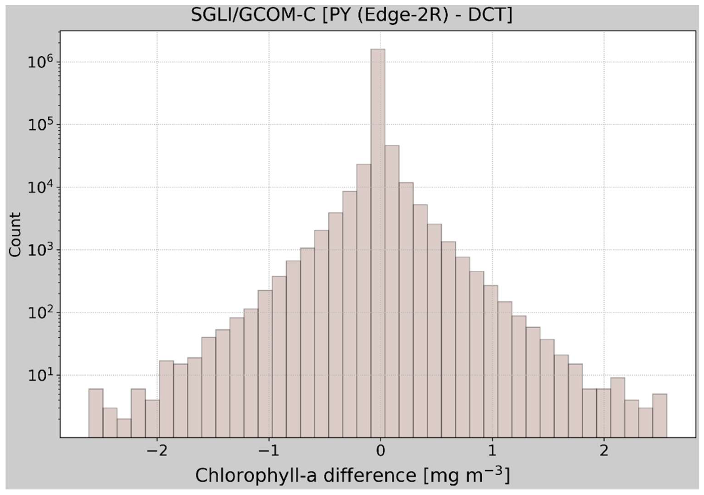
JAXA provides a Windows-based Earth Observation Data Conversion Tool (DCT, https://gportal.jaxa.jp/gpr/information/tool?lang=en, accessed on 4 August 2022) that can be used to remap SGLI/GCOM-C data prior to ingestion into the GEE. With this tool, we can select the same NN resampling as in our Python-based remapping procedure (PY) but it is not clear from the documentation how this tool applies the NN method during the remapping. As such, it is difficult to have an objective comparison with our procedure. Moreover, the target projection is also fixed to geodetic latitude/longitude. Our brief comparison of the DCT remapped data with the swath and the PY method showed consistent statistical metrics similar to those of remapped (R and 2R, Table 2) except for the count. However, spatial differences between the PY and DCT were also evident (https://code.earthengine.google.com/4cf92c3e77a5ec53154ec6a168c870bd?hideCode=true). In this link, the detailed spatial differences between the PY- and DCT-based remapping at the subpixel level were apparent, as the latter uses a degree-based gridding while the former uses a distance-based step. The DCT had a significant increase in valid pixel count—83% relative to swath and 39% relative to PY. The histogram of the difference between PY and DCT highlighted these subpixel differences (Figure 4) since the statistical characteristics within a given polygon remained consistent (please see the histograms in the GEE link above). It would be interesting to see how these differences in swath remapping strategies are reflected in validation analysis as discussed for Level-2 and higher-level products in [25]. However, such discussion is beyond the scope of this study.
Similarly, NASA also has an official data analysis software, SeaDAS, primarily designed for OC data (https://seadas.gsfc.nasa.gov/downloads/, accessed on 16 August 2022). SeaDAS is able to remap and directly output GeoTIFF files. Testing the suitability of different mapping software is out of scope of the current study. With the SeaDAS, we can also use the same Lambert Azimuthal Equal Area projection and NN method as in the PY remapping. Thus, we expect that the results would be consistent between the two software.

4. Discussion

We introduced a simple procedure to make Level-2 OC geophysical parameters at their native spatiotemporal resolution, as well as the associated quality flags, readily available in the GEE. Once ingested these datasets can be curated and made available through the GEE data catalog. The results clearly confirmed that the distributions of the swath versus remapped data remain consistent. This, in part, is because the mapping strategy only considers a single swath so that issues introduced by temporal averaging are excluded. The choice of the target projection, the Lambert Azimuthal Equal Area projection, also leads to transferring the swath resolution onto the target projection, thereby effectively avoiding spatial distortions and possible errors introduced by equirectangular grids. Space agencies routinely remap swath data onto a spatial grid over a certain time period. Some of these spatiotemporally aggregated products mapped onto a nearly equal-area integerized sinusoidal grid [26] are denoted as Level-3 binned products. Globally binned maps are then used to create standard mapped products on equirectangular (Plate Carrée) projection. While Level-3 products are more accessible to non-expert users than products at lower processing levels, their spatial resolution is often coarser than the original Level-2 data and not attractive for applications in nearshore and/or inland waters [27]. Moreover, satellite-to-in-situ validation analysis showed that the spatial and/or temporal binning of swath data beyond the swath spatiotemporal reference introduce uncertainties that result in discrepancies between Level-2 and Level-3 performance metrics [28]. Our discussion is simply focused on the swath reprojection strategies. Once the data is ported into the GEE, its application would still require quality screening prior to its use.
This study does not intend to introduce a new standard for mapping Level-2 OC data, but emphasizes the opportunities provided by the flexibility and scalability of GEE for OC applications. The availability of higher spatial resolution datasets has been increasing in recent years, but advances in their applications have been slow, in part, because of challenges in working with these datasets using conventional means, in which case GEE can fill the gap.
The availability of high-resolution Landsat and other public datasets in GEE has allowed the study of various environmental changes—extending to both management and conservation activities—globally at unprecedented spatial and temporal scales [16,29,30,31,32,33]. It the coastal oceans, Landsat and Sentinel data are also being used to map the distribution, abundance, and changes in submerged aquatic ecosystems. Such information can provide the scientific basis for formulating conservation policies [17,18]. The Global Eutrophication Watch [2] is among the few OC data application studies to leverage the potentials of GEE for interactive mapping of global change in coastal ecosystems. The lack of medium to higher resolution geophysical data from OC sensors remains a limiting factor. However, even the application to open ocean remains poor within the OC community. The GEE IssueTracker includes researcher and practitioner requests for addition of OC datasets at their native spatial resolution for monitoring of coastal water phenomena, such as cyanobacteria blooms (e.g., issues 34740451 and 139056084). This study, in part, responds to this demand by contributing a simple but practical way of porting Level-2 OC datasets into GEE. Ideally, data ingestion would be sustainable if it is happening in concert with space agencies or if a GEE team directly performs these steps.
We anticipate that this study will pave the way to making OC datasets at their native spatiotemporal resolutions readily accessible through the GEE data catalog. Such data, among others, can benefit efforts to develop regional algorithms and OC data validation activities. Traditionally, validation activities involve (1) data download from the data providers and (2) match-ups analysis with in situ data on a local computer. These steps, in particular (1), would be unnecessary if the data were readily accessible in GEE. Intercalibration of OC products is another activity that can benefit enormously from the power of GEE. Terauchi et al. [34], for instance, introduced a procedure to spatially and temporally blend regional and global chlorophyll algorithms in the Northwest Pacific region. The introduced procedure was used to generate a long-term consistent dataset of chlorophyll data (1997-present) and the generated data were uploaded into GEE and applied in the coastal eutrophication study of Maúre et al. [2]. While the processing steps, as in Terauchi et al., are necessary, they are laborious and resource intensive. The availability of these datasets in GEE can further enhance the efforts of the Group of Earth Observations (GEO) in making Earth observations data more accessible to support science and decision making [7]. The partnership between GEO and GEE is one example of the efforts being made toward the use of Earth observations in support of sustainable development goals. The availability of OC datasets in GEE will contribute to the ocean decade challenges for collective impact, in which challenge 7 is aimed at expanding the global ocean observing system.

Author Contributions

Conceptualization, E.d.R.M.; methodology, E.d.R.M.; software, E.d.R.M.; formal analysis, E.d.R.M.; investigation, E.d.R.M.; resources, E.d.R.M., G.T. and S.I.; data curation, E.d.R.M. and S.I.; writing—original draft preparation, E.d.R.M.; writing—review and editing, E.d.R.M., G.T. and S.I.; visualization, E.d.R.M.; project administration, G.T.; funding acquisition, E.d.R.M. and G.T. All authors have read and agreed to the published version of the manuscript.

Funding

This research received no external funding.

Data Availability Statement

The sample files were obtained from NASA’s OB.DAAC (https://oceancolor.gsfc.nasa.gov/, accessed on 23 August 2022) for the MODIS/Aqua sensor and JAXA’s G-Portal (https://gportal.jaxa.jp/gpr/?lang=en, accessed on 17 August 2022) for the SGLI/GCOM-C sensor. The preprocessed and GEE ingested version of the sample file for MODIS/Aqua can be found at GEE address “projects/ee-eutrophication-gee4geo/assets/OCEANDATA/L2/Test/A2022125035500_L2_LAC_OC”. The PY version of the SGLI/GCOM-C can be found at “projects/ee-eutrophication-gee4geo/assets/GC1SG1_202205030152F05810_L2SG_IWPRQ_3000_py”, and the DCT version is located at “projects/ee-eutrophication-gee4geo/assets/ GC1SG1_202205030152F05810_L2SG_IWPRQ_3000_dct”. All three files are visualized in GEE at the link https://code.earthengine.google.com/19cc78d1ef66def625c664010de8ea85?hideCode=true. The links also include the center and edge polygon data used in the text.

Acknowledgments

This work was made possible through the support received from the Ministry of the Environment of Japan, the Toyama Prefectural Government, and the Northwest Pacific Region Environmental Cooperation Center established to promote the Action Plan for the Protection, Management and Development of the Marine and Coastal Environment of the Northwest Pacific Region as a part of the Regional Seas Programme of the United Nations Environment Programme. This paper was inspired by the Marine Coastal Eutrophication project, one of the 32 funding projects aimed at tackling some of the world’s greatest challenges using open Earth data by the Group on Earth Observations (GEO) and GEE. The authors thank members of the Marine Coastal Eutrophication project for insightful discussions. We thank NASA and JAXA for providing the ocean color data. Pyresample was used for the reprojection of swath data in Python and the figures were produced using Matplotlib library. Code snippets were formatted using syntax highlighter http://hilite.me/.

Conflicts of Interest

The authors declare no conflict of interest.

Appendix A

Illustrations of the swath pixel resolution at the swath center and edge, description of the target projection, code snippets for the initialization of target projection and translation of bounds, and the remapping of the SGLI/GCOM sample data.
Figure A1. Illustrations of pixel resolution of swath (red) and of map-projected grid (gray) for MODIS/Aqua (a,b) and SGLI/GCOM-C (c,d). (a,c) Shows the pixel frame at the swath edge where the resolution degrades significantly. (b,d) Same as (a,c) but for the sub-satellite location with the resolution equal to the nominal value. The dots represent the pixel center for the swath (red) and map-projected (gray) grid. Note how far the pixels at the target grid projection are located from the swath center.
Remotesensing 14 04906 g0a1
Figure A2. Python code snippet for projection initialization. The Lambert azimuthal equal-area projection (LAEA) is initialized with the center located at the swath scan line center longitude/latitude median point. The initialized projection was then used to translate the swath bounds in degrees into the target projection distances in meters. WGS84 stands for World Geodetic System (WGS) 1984, consisting of a reference ellipsoid, a standard coordinate system, altitude data, and a geoid.
Remotesensing 14 04906 g0a2
Figure A3. Python code snippet of transform_bounds used to convert the swath bounds to projected bounds while taking into account the nonlinearity of the transformations (https://pyproj4.github.io/pyproj/stable/api/transformer.html, accessed on 14 July 2022). EPSG:4326 is the Spatial Reference ID for the WGS84, latitude/longitude coordinate system based on the Earth’s center of mass.
Remotesensing 14 04906 g0a3
Figure A4. Python code snippet of Pyresample area definition for the target projection. The area definition is used in step 1 of swath reprojection.
Remotesensing 14 04906 g0a4
Figure A5. Example of coordinate system and image structure output by “gdalinfo” for the MODIS/Aqua target map projection. Note that the corner coordinates are reported in metric distances along with corresponding latitude and longitude values.
Remotesensing 14 04906 g0a5
Figure A6. Same as in Figure 2 but for SGLI/GCOM-C. Sample data used is indicated in Table 1. At the center box, a patch of isolated high chlorophyll can be seen swirling clockwise. The area is known to be an eddy rich with significant impacts on phytoplankton bloom timing [35,36].
Remotesensing 14 04906 g0a6

References

  1. Groom, S.; Sathyendranath, S.; Ban, Y.; Bernard, S.; Brewin, R.; Brotas, V.; Brockmann, C.; Chauhan, P.; Choi, J.; Chuprin, A.; et al. Satellite Ocean Colour: Current Status and Future Perspective. Front. Mar. Sci. 2019, 6, 485. [Google Scholar] [CrossRef]
  2. Maúre, E.d.R.; Terauchi, G.; Ishizaka, J.; Clinton, N.; DeWitt, M. Globally Consistent Assessment of Coastal Eutrophication. Nat. Commun. 2021, 12, 6142. [Google Scholar] [CrossRef]
  3. Feng, C.; Ishizaka, J.; Saitoh, K.; Mine, T.; Zhou, Z. Detection and Tracking of Chattonella Spp. and Skeletonema Spp. Blooms Using Geostationary Ocean Color Imager (GOCI) in Ariake Sea, Japan. J. Geophys. Res. Ocean. 2021, 126, e2020JC016924. [Google Scholar] [CrossRef]
  4. Stumpf, R.P.; Culver, M.E.; Tester, P.A.; Tomlinson, M.; Kirkpatrick, G.J.; Pederson, B.A.; Truby, E.; Ransibrahmanakul, V.; Soracco, M. Monitoring Karenia Brevis Blooms in the Gulf of Mexico Using Satellite Ocean Color Imagery and Other Data. Harmful Algae 2003, 2, 147–160. [Google Scholar] [CrossRef]
  5. Cannizzaro, J.P.; Carder, K.L.; Chen, F.R.; Heil, C.A.; Vargo, G.A. A Novel Technique for Detection of the Toxic Dinoflagellate, Karenia Brevis, in the Gulf of Mexico from Remotely Sensed Ocean Color Data. Cont. Shelf Res. 2008, 28, 137–158. [Google Scholar] [CrossRef]
  6. Siswanto, E.; Ishizaka, J.; Tripathy, S.C.; Miyamura, K. Detection of Harmful Algal Blooms of Karenia Mikimotoi Using MODIS Measurements: A Case Study of Seto-Inland Sea, Japan. Remote Sens. Environ. 2013, 129, 185–196. [Google Scholar] [CrossRef]
  7. IOCCG. Earth Observations in Support of Global Water Quality Monitoring; Greb, S., Dekker, A., Binding, C., Eds.; IOCCG Report Series, No. 17; International Ocean Colour Coordinating Group: Dartmouth, NS, Canada, 2018; Volume 17. [Google Scholar]
  8. Huntington, J.L.; Hegewisch, K.C.; Daudert, B.; Morton, C.G.; Abatzoglou, J.T.; McEvoy, D.J.; Erickson, T. Climate Engine: Cloud Computing and Visualization of Climate and Remote Sensing Data for Advanced Natural Resource Monitoring and Process Understanding. Bull. Am. Meteorol. Soc. 2017, 98, 2397–2409. [Google Scholar] [CrossRef]
  9. Gorelick, N.; Hancher, M.; Dixon, M.; Ilyushchenko, S.; Thau, D.; Moore, R. Google Earth Engine: Planetary-Scale Geospatial Analysis for Everyone. Remote Sens. Environ. 2017, 202, 18–27. [Google Scholar] [CrossRef]
  10. Tamiminia, H.; Salehi, B.; Mahdianpari, M.; Quackenbush, L.; Adeli, S.; Brisco, B. Google Earth Engine for Geo-Big Data Applications: A Meta-Analysis and Systematic Review. ISPRS J. Photogramm. Remote Sens. 2020, 164, 152–170. [Google Scholar] [CrossRef]
  11. Zhao, Q.; Yu, L.; Li, X.; Peng, D.; Zhang, Y.; Gong, P. Progress and Trends in the Application of Google Earth and Google Earth Engine. Remote Sens. 2021, 13, 3778. [Google Scholar] [CrossRef]
  12. Yang, L.; Driscol, J.; Sarigai, S.; Wu, Q.; Chen, H.; Lippitt, C.D. Google Earth Engine and Artificial Intelligence (AI): A Comprehensive Review. Remote Sens. 2022, 14, 3253. [Google Scholar] [CrossRef]
  13. Kumar, L.; Mutanga, O. Google Earth Engine Applications Since Inception: Usage, Trends, and Potential. Remote Sens. 2018, 10, 1509. [Google Scholar] [CrossRef]
  14. Mutanga, O.; Kumar, L. Google Earth Engine Applications. Remote Sens. 2019, 11, 591. [Google Scholar] [CrossRef]
  15. Amani, M.; Ghorbanian, A.; Ahmadi, S.A.; Kakooei, M.; Moghimi, A.; Mirmazloumi, S.M.; Moghaddam, S.H.A.; Mahdavi, S.; Ghahremanloo, M.; Parsian, S.; et al. Google Earth Engine Cloud Computing Platform for Remote Sensing Big Data Applications: A Comprehensive Review. IEEE J. Sel. Top. Appl. Earth Obs. Remote Sens. 2020, 13, 5326–5350. [Google Scholar] [CrossRef]
  16. Hansen, M.C.; Potapov, P.V.; Moore, R.; Hancher, M.; Turubanova, S.A.; Tyukavina, A.; Thau, D.; Stehman, S.V.; Goetz, S.J.; Loveland, T.R.; et al. High-Resolution Global Maps of 21st-Century Forest Cover Change. Science 2013, 342, 850–853. [Google Scholar] [CrossRef]
  17. Mora-Soto, A.; Palacios, M.; Macaya, E.C.; Gómez, I.; Huovinen, P.; Pérez-Matus, A.; Young, M.; Golding, N.; Toro, M.; Yaqub, M.; et al. A High-Resolution Global Map of Giant Kelp (Macrocystis Pyrifera) Forests and Intertidal Green Algae (Ulvophyceae) with Sentinel-2 Imagery. Remote Sens. 2020, 12, 694. [Google Scholar] [CrossRef]
  18. Chen, G.; Jin, R.; Ye, Z.; Li, Q.; Gu, J.; Luo, M.; Luo, Y.; Christakos, G.; Morris, J.; He, J.; et al. Spatiotemporal Mapping of Salt Marshes in the Intertidal Zone of China during 1985–2019. J. Remote Sens. 2022, 2022, 9793626. [Google Scholar] [CrossRef]
  19. Mouw, C.B.; Greb, S.; Aurin, D.; DiGiacomo, P.M.; Lee, Z.; Twardowski, M.; Binding, C.; Hu, C.; Ma, R.; Moore, T.; et al. Aquatic Color Radiometry Remote Sensing of Coastal and Inland Waters: Challenges and Recommendations for Future Satellite Missions. Remote Sens. Environ. 2015, 160, 15–30. [Google Scholar] [CrossRef]
  20. Luang-on, J.; Ishizaka, J.; Buranapratheprat, A.; Phaksopa, J.; Goes, J.I.; Kobayashi, H.; Hayashi, M.; Maúre, E.d.R.; Matsumura, S. Seasonal and Interannual Variations of MODIS Aqua Chlorophyll—A (2003–2017) in the Upper Gulf of Thailand Influenced by Asian Monsoons. J. Oceanogr. 2022, 78, 209–228. [Google Scholar] [CrossRef]
  21. Cartwright, P.J.; Fearns, P.R.C.S.; Branson, P.; Cutler, M.V.W.; O’leary, M.; Browne, N.K.; Lowe, R.J. Identifying Metocean Drivers of Turbidity Using 18 Years of Modis Satellite Data: Implications for Marine Ecosystems under Climate Change. Remote Sens. 2021, 13, 3616. [Google Scholar] [CrossRef]
  22. Lomas, M.W.; Bates, N.R.; Johnson, R.J.; Steinberg, D.K.; Tanioka, T. Adaptive Carbon Export Response to Warming in the Sargasso Sea. Nat. Commun. 2022, 13, 1211. [Google Scholar] [CrossRef]
  23. Ishizaka, J.; Hirawake, T.; Toratani, M.; Frouin, R. Special Section for Second-Generation Global Imager (SGLI). J. Oceanogr. 2022, 78, 185–186. [Google Scholar] [CrossRef]
  24. Choi, J.K.; Min, J.E.; Noh, J.H.; Han, T.H.; Yoon, S.; Park, Y.J.; Moon, J.E.; Ahn, J.H.; Ahn, S.M.; Park, J.H. Harmful Algal Bloom (HAB) in the East Sea Identified by the Geostationary Ocean Color Imager (GOCI). Harmful Algae 2014, 39, 295–302. [Google Scholar] [CrossRef]
  25. Maneewongvatana, S.; Mount, D. Analysis of Approximate Nearest Neighbor Searching with Clustered Point Sets. arXiv 1999, arXiv:cs/9901013. [Google Scholar] [CrossRef]
  26. Campbell, J.W.; Blaisdell, J.M.; Darzi, M. SeaWiFS Data Products: Spatial and Temporal Binning Algorithms; Hooker, S.B., Firestone, E.R., Acker, J.G., Eds.; SeaWiFS Technical Report Series; Technical Memorandum 104566; NASA Goddard Space Flight Center: Greenbelt, MD, USA, 1995; Volume 32.
  27. Dorji, P.; Fearns, P. Impact of the Spatial Resolution of Satellite Remote Sensing Sensors in the Quantification of Total Suspended Sediment Concentration: A Case Study in Turbid Waters of Northern Western Australia. PLoS ONE 2017, 12, e0175042. [Google Scholar] [CrossRef]
  28. Scott, J.P.; Werdell, P.J. Comparing Level-2 and Level-3 Satellite Ocean Color Retrieval Validation Methodologies. Opt. Express 2019, 27, 30140. [Google Scholar] [CrossRef]
  29. Dong, J.; Xiao, X.; Menarguez, M.A.; Zhang, G.; Qin, Y.; Thau, D.; Biradar, C.; Moore, B. Mapping Paddy Rice Planting Area in Northeastern Asia with Landsat 8 Images, Phenology-Based Algorithm and Google Earth Engine. Remote Sens. Environ. 2016, 185, 142–154. [Google Scholar] [CrossRef]
  30. Teluguntla, P.; Thenkabail, P.; Oliphant, A.; Xiong, J.; Gumma, M.K.; Congalton, R.G.; Yadav, K.; Huete, A. A 30-m Landsat-Derived Cropland Extent Product of Australia and China Using Random Forest Machine Learning Algorithm on Google Earth Engine Cloud Computing Platform. ISPRS J. Photogramm. Remote Sens. 2018, 144, 325–340. [Google Scholar] [CrossRef]
  31. Lewkowicz, A.G.; Way, R.G. Extremes of Summer Climate Trigger Thousands of Thermokarst Landslides in a High Arctic Environment. Nat. Commun. 2019, 10, 1329. [Google Scholar] [CrossRef]
  32. Jahromi, M.N.; Jahromi, M.N.; Zolghadr-Asli, B.; Pourghasemi, H.R.; Alavipanah, S.K. Google Earth Engine and Its Application in Forest Sciences. In Environmental Science and Engineering; Springer: Cham, Switzerland, 2021; pp. 629–649. [Google Scholar]
  33. Singha, M.; Dong, J.; Sarmah, S.; You, N.; Zhou, Y.; Zhang, G.; Doughty, R.; Xiao, X. Identifying Floods and Flood-Affected Paddy Rice Fields in Bangladesh Based on Sentinel-1 Imagery and Google Earth Engine. ISPRS J. Photogramm. Remote Sens. 2020, 166, 278–293. [Google Scholar] [CrossRef]
  34. Terauchi, G.; Maúre, E.d.R.; Yu, Z.; Wu, Z.; Kachur, V.; Lee, C.; Ishizaka, J. Assessment of Eutrophication Using Remotely Sensed Chlorophyll-a in the Northwest Pacific Region. In Remote Sensing of the Open and Coastal Ocean and Inland Waters; Frouin, R.J., Murakami, H., Eds.; SPIE: Bellingham WA, USA, 24 October 2018; p. 17. [Google Scholar] [CrossRef]
  35. Maúre, E.R.; Ishizaka, J.; Sukigara, C.; Mino, Y.; Aiki, H.; Matsuno, T.; Tomita, H.; Goes, J.I.; Gomes, H.R.; Goes, J.I.; et al. Mesoscale Eddies Control the Timing of Spring Phytoplankton Blooms: A Case Study in the Japan Sea. Geophys. Res. Lett. 2017, 44, 11,115–11,124. [Google Scholar] [CrossRef]
  36. Maúre, E.R.; Ishizaka, J.; Aiki, H.; Mino, Y.; Yoshie, N.; Goes, J.I.; Gomes, H.R.; Tomita, H. One-Dimensional Turbulence-Ecosystem Model Reveals the Triggers of the Spring Bloom in Mesoscale Eddies. J. Geophys. Res. Ocean. 2018, 123, 6841–6860. [Google Scholar] [CrossRef]
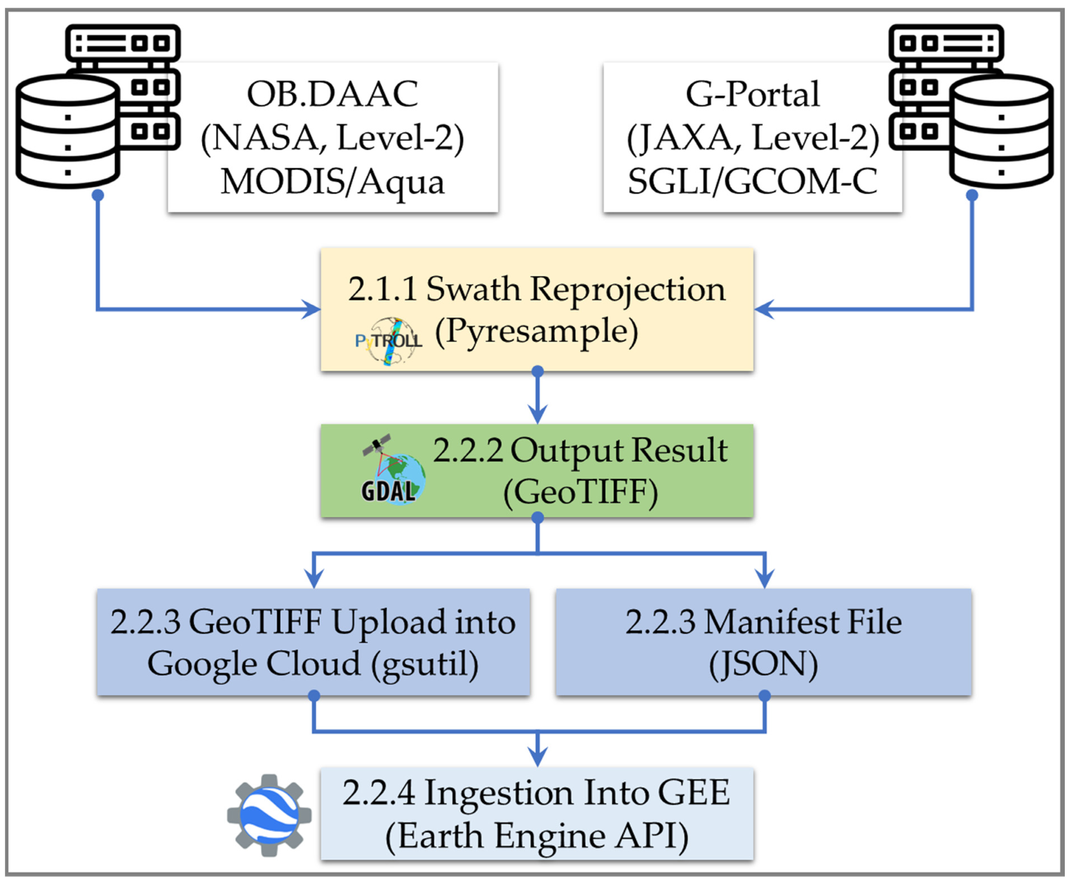
Figure 1. Schematic of the data reprojection and ingestion into GEE. The numbers in the steps correspond to the sub-sections with detailed explanation given in the text.
Remotesensing 14 04906 g001
Figure 2. Reprojection of swath data for the MODIS/Aqua file (Table 1). (a) Swath image with the nadir track shown as red dotted line. (b,c) Swath subset data from the red polygon at the swath edge (b) and at the nadir view (c). (d,e) Reprojected data with cutoff distance (radius of influence) equal to the spatial resolution (R) for swath edge (d) and nadir view (e). (f,g) Same as (d,e) but for the cutoff distance equal to 2R. The red dots at the start and end of the dotted line indicate the swath start and end center positions, respectively. The reprojection was done using the NN method. The impact of using R (d) versus 2R (f) was evident at the swath edge. A similar example is also given for SGLI/GCOM-C in Figure A6.
Remotesensing 14 04906 g002
Figure 3. Density histogram of swath versus remapped image: (a,c) chlorophyll data and (b,d) the frequency distributions of associated quality flag information. (a,b) Diagrams were obtained from MODIS/Aqua data (Figure 2) and (c,d) from SGLI/GCOM-C data (Figure A6). These diagrams were created from the red polygons highlighted at the swath edge in the respective figures. The overlaid curves are the probability distribution functions (PDF) for the same samples. The inset compares the two PDFs (swath versus remapped). Note the increase in pixel number in the range of 2 to 10 mg m–3 associated with the high chlorophyll at the swath edge in (a). Description of MODIS/Aqua flags can be obtained from https://oceancolor.gsfc.nasa.gov/atbd/ocl2flags/, accessed on 29 July 2022. For more on SGLI/GCOM-C quality flags, see https://suzaku.eorc.jaxa.jp/GCOM_C/data/files/ATBD_ocean_ac_murakami_v2_en.pdf, accessed on 23 July 2022.
Remotesensing 14 04906 g003
Figure 4. Chlorophyll-a difference between PY (Python-based) and DCT (JAXA’s Earth Observation Data Conversion Tool based) remapped data. Note the logarithmic scale on the y-axis.
Remotesensing 14 04906 g004
Table 1. List of the files used in the data ingestion demo case. The Python code with the procedure discussed in this study is available from the link https://github.com/npec/ee-oc-data-ingestion.
Sensor/SatelliteData File
MODIS/AquaA2022125035500.L2_LAC_OC.nc
SGLI/GCOM-CGC1SG1_202205030152F05810_L2SG_IWPRQ_3000.h5
GC1SG1_202205030152F05810_L2SG_NWLRQ_3000.h5
Table 2. Descriptive statistics for the swath and reprojected data in the subset area at the swath edge. The statistics were obtained on log-transformed data and results back-transformed to linear. All data are in mg m–3 except for count, which is the number of pixels in the polygon extract.
MODIS/Aqua (Edge)SGLI/GCOM-C (Edge)
SwathRemapped (R)Remapped (2R)Swath Remapped (R)Remapped (2R)
Count36,59172,82792,0721,313,1971,720,4051,720,405
Mean0.7400.7410.7950.2930.3070.307
STD1.7031.6981.8362.0822.1192.119
Min0.2690.2690.2690.0020.0020.002
25%0.5180.5210.5310.1900.1940.194
50%0.6850.6890.7160.2460.2540.254
75%0.9060.9060.9590.4580.4830.483
Max93.19693.19693.19689.96389.96389.963
Publisher’s Note: MDPI stays neutral with regard to jurisdictional claims in published maps and institutional affiliations.