1. Introduction
The detection of non-line-of-light (NLOS) targets in the urban environment has an important application value in the fields of military and social security, such as urban warfare, indoor rescue and disaster rescue [
1,
2,
3,
4,
5,
6]. In recent years, NLOS target detection has paid more attention to intelligent driving, mobile communication and other areas of life [
7,
8,
9,
10,
11,
12]. Normally, NLOS scenarios can be divided into two types. One is that the targets exist in an enclosed space, and the other is that the targets hide behind the corner. Unlike the common target detection in the line-of-sight (LOS) region, the electromagnetic (EM) wave is unable to be transmitted directly to the targets in the NLOS scenarios. However, the NLOS targets can be detected by penetration or a multipath. Among them, targets in the enclosed environments are usually detected by through-the-wall (TTW) radar, which utilizes the penetration of low-frequency EM waves to detect the target behind the wall [
13,
14]. In addition, targets behind the corner can be detected by multipath propagation, including diffraction, specular reflection and diffuse reflection.
The application of multipath in radar originated from a multipath exploitation project in [
15,
16]. In the early research, the feasibility analysis of obtaining NLOS target information from multipath signals is mainly focused [
17,
18,
19,
20]. Recently, using multipath signals to detect NLOS targets has gradually become universal. According to single and multiple multipath signals, NLOS localization can be classified into two types. The first type only utilizes a single robust multipath echo, which is very common in the millimeter wave (MMW) radar. Since the diffraction ability of EM wave is weak in the MMW band and the severe attenuation of higher-order multipath, only the first-order reflection path is prone to utilizing it effectively. In [
21], a localization algorithm based on phase comparison among the multiple channels was proposed. The false target range was obtained via exploiting the fast Fourier transform (FFT) and the false target azimuth was derived by the phase differences between echoes among the multiple channels. Then, the true target position was inversely calculated according to the geometric symmetry of the false target and true target. In [
22], target localization was realized by a synthetic bistatic MMW radar. A virtual bistatic was formed through the movement of MMW radar. The approach avoided the disadvantage of the inaccurate direction of the arrival (DOA) estimation. It is noticed that the above methods applied only the single bounce multipath. The other type focuses on exploiting multiple multipath signals in low frequency. In the low-frequency band, both diffraction and reflection can be exploited, and there will be more robust multipaths to extract target information. Some studies have been conducted to localize targets via multiple paths. In [
23], a method of NLOS human target detection in a real scene via one- and two-wall reflections was proposed. In the experiments, two moving targets were detected simultaneously and separated when they kept a farther distance each other. Subsequently, a moving NLOS target localization method based on numerical simulation was proposed in [
24]. Specifically, the scanning narrow beam radar system was utilized to prevent the mutual interference of various multipaths. This solution assumed that radar can provide sufficient angular resolution to cover a monitored region. Combining the information of radar beam direction and the detected distance of the target, the position of the target could be easily obtained.
Different from the narrow-beam radar system, the wide-beam radar finds it difficult to obtain the angle information from the paths, resulting in the mutual interference of the multipaths, namely the ambiguity of the multipath propagation. The increase in positioning error was caused by the multipath ambiguity. In order to deal with this problem, some methods were proposed in related works [
25,
26,
27]. For example, a target localization method based on diffraction path, one-bounce reflection path and their combination was proposed in [
25]. The multipath echoes were separated by a parallel threshold-based detector. After that, a global nearest-neighbor (GNN) algorithm was exploited to modify the range estimates of returns. The obtained range estimates were assigned to the corresponding propagation paths, mitigating the ambiguities of the multipath. The experimental results demonstrated that correct location estimation was achieved with robust multipath range estimates produced by the GNN algorithm. In [
26], considering the complexity of the multipath measurement model and the nonlinear relationship between target position and multipath delay, a filter called the generalized likelihood ratio test (GLRT) particle filter was presented, which succeeded to alleviate the ambiguities and improve the root-mean-square error considerably. It is worth noting that this method is dependent on the assumption of an ideal signal model without clutter. Nevertheless, multipath signals can be severely interfered by clutters in the practical environment. Two algorithms were developed in [
27] to reduce ambiguities in localization with taking into account information from different paths simultaneously. Firstly, a multipath-propagation-based matched filter was proposed. The filter jointly processed the information provided by the multipath returns to detect and estimate the location of the NLOS target. Only the rough information of the scenario was required as a prior. Subsequently, a square law combiner (SLC) algorithm was designed to realize the same work by computing an incoherent integration for the multipath delays. However, there is diversity in the computation and memory requirements between two algorithms. Furthermore, owing to the existence of special paths, a path selection algorithm was designed to optimize the detection probability. The simulated and experimental results demonstrated that the two algorithms could improve detection performance and retrieve the target position with higher accuracy.
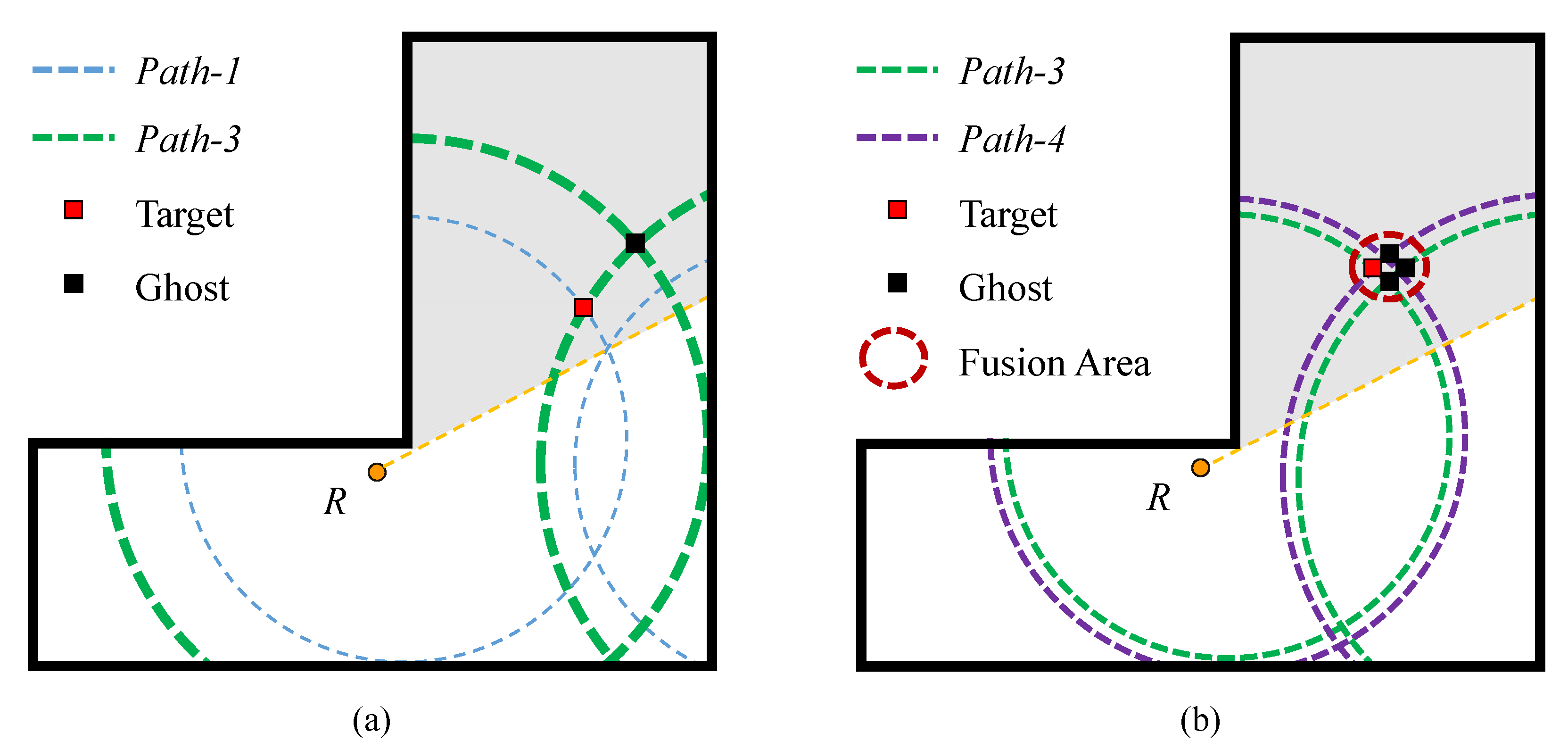
The above methods need to precisely separate the desired multipaths. However, in the actual situation of multiple targets, multipaths are more likely to interfere and alias with each other, which makes it difficult to accurately extract the multipaths corresponding to the targets. Different from the methods based on multipath separation, our previous work [
28] proposed an approach of direct multipath imaging based on the propagation characteristics of different multipath signals. This approach avoided separating or matching the multipath, but directly mapped radar echo into multiple imaging trajectories according to the position of virtual radars. The target was focused by incoherent addition at last. The experimental results manifested that the target could be located via this method under the circumstances of interference. Whereas, the ghosts appeared in the results after the difference in energy between the multipaths, which were more prominent in multi-objective cases. As a continuation of the previous study, this paper focuses on solving the ghost problem. In order to suppress ghosts, the view dependence of ghosts and the limitation of single view are considered. Therefore, utilizing a dual-view for detection is determined. The multipaths are strengthened respectively based on the dual-view, and then divided into two parts of the corresponding view for multipath imaging. Due to the different distribution of ghosts from the two views, the staggered ghosts can be eliminated by image fusion. The main contents and innovations are as follows.
The causes of producing ghosts in the previous method are analyzed in detail from the perspective of a range profile, and the distribution of the ghost is demonstrated, respectively. Two key factors influencing the ghost formation are revealed.
Based on the directivity of the radar beam, we propose to abandon the use of single view detection but employ dual-view joint detection to achieve the reinforcement of the weak path.
To maximize the usage efficiency of the path and decrease the accumulation of ghosts, the selected multipaths are firstly divided into two complementary parts based on the two views. Then, the two parts are applied to perform multipath imaging, respectively. By utilizing the difference of ghost distribution in the dual-view, multiplication fusion of the imaging results is carried out to eliminate the staggered ghosts.
Real experiments are conducted in both a single and double target scenario, verifying the superiority of the proposed approach in comparison with the direct multipath imaging.
The rest of this article is organized as follows. In
Section 2, the multipath propagation model of the L-shaped corner scenario is established. In
Section 3, the causes and situations of producing ghosts by the previous method [
28] are analyzed, and the key factors affecting the ghosts are summarized.
Section 4 proposes a novel method based on a dual-view observation to suppress ghosts. Real experimental results validate the effectiveness of the method in
Section 5 and the related discussions are presented in
Section 6. The paper is concluded in
Section 7.
2. Multipath Propagation Model
In this section, a typical L-shaped multipath propagation model is established. In addition, to achieve more accurate positioning, six saliency multipaths are picked out from the propagation model as a preparation for the imaging approach.
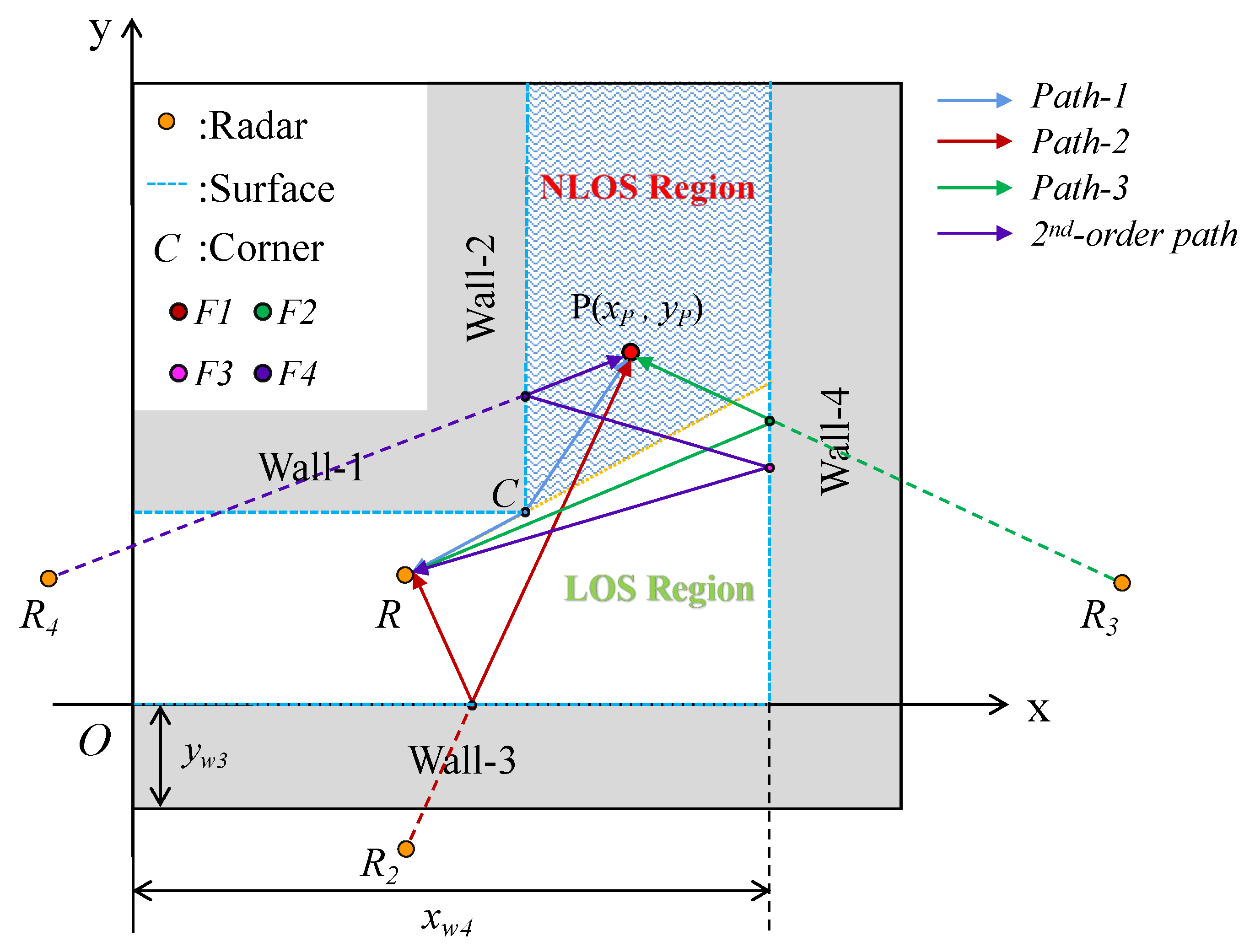
The L-shaped corner scenario, as a typical scene of NLOS environment, is the multipath propagation scenario considered in this paper. By abstracting the real sheltered environment, an L-shaped scenario is established with a two-dimensional Cartesian coordinate system, as shown in
Figure 1. The origin
is placed at the left endpoint of upper surface of Wall-3. To be specific, the L-shaped environment consists of four walls. Wall-1 and Wall-2 form the corner
C, which is located at
,
. Wall-3 and Wall-4 fill the exterior of the L-shaped corridor. The ordinate of the upper surface of Wall-3 is
, and the abscissa of the left surface of Wall-4 is
.
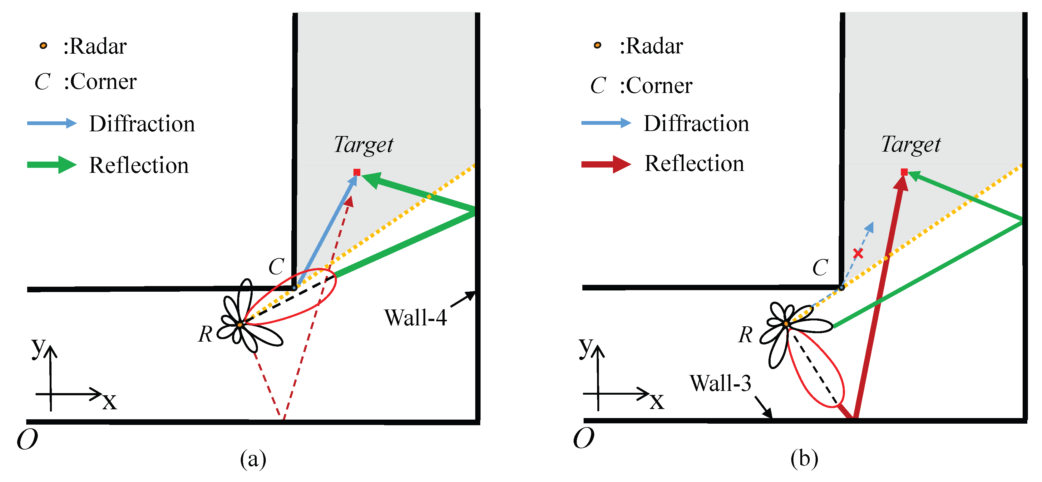
A single-channel UWB radar is used to sense the NLOS human target. To simplify the scene model, it is assumed that the EM reflection at all walls is specular, and the rough layout of the L-shaped corner scenario is known as a prior. In
Figure 1, the radar
toward the corner
C is located at the corridor of Wall-1 and Wall-3. The whole scene is divided into the LOS region and NLOS region by a straight line through
R and
C. The target
(
,
) is located in the NLOS region of another corridor of Wall-2 and Wall-4. The signal can be directly reflected by the target in the LOS region and recovered by the receiver, yet the target in the NLOS region needs to be detected by diffraction at the corner and reflection on the wall. The reflection path can be regarded as a direct propagation of the EM wave, which is emitted by mirror symmetric virtual radar with respect to the reflective wall. To obtain a saliency path, only diffraction and first-order reflection are considered, primarily. Three monotonic paths can be gathered from the L-shaped environment.
: . The EM wave transmits to the corner and diffracts to the target, and then returns along the original path. Since the position of the radar to the corner C remains unchanged, C can be regarded as a new virtual radar source after the diffraction.
: . The EM wave is reflected on and reflection propagates to the target, then it returns along the original path. According to the reflection theorem, the path can be expressed as , where represents the mirror symmetry radar of R with respect to the upper surface of Wall-3.
: . The EM wave is reflected on and reflection propagates to the target. The echo returns according to the original path. Likewise, the path can be expressed as , where denotes the mirror symmetry radar of R with respect to the left surface of Wall-4.
Furthermore, the high-order reflection path will be formed due to continuous reflection on the walls, such as the second-order path:
. It is worth noting that the signal suffers severe attenuation with more bounce reflection. Since the continuous ejection of signals between walls, the length of high-order paths is highly correlated with the width of the corridor. It means that the air attenuation of high-order reflection varies in L-shaped scenarios with different widths, namely, the energy of high-order reflection return is unstable. The experimental result in [
29] shows that the energy of EM wave attenuates significantly alter, reflecting twice between walls. To ensure the salience of the path, the second-order reflection path and higher-order reflection path are disused, and only the diffraction path and the first-order reflection path are considered.
Besides the pure single paths, three new composite paths can be obtained by combining single paths.
: . The EM wave transmits to the corner and diffracts to the target, and then reflected back to the receiver on .
: . The EM wave propagates to the target by diffraction at the corner, and then reflects back to the receiver on .
: . The EM wave propagates to the target by reflection on , and then reflects back to the receiver on .
Thus, six robust propagation paths are selected as described, which will be utilized in multipath imaging. Moreover, these saliency paths are related to virtual radar sources
C,
and
; thus, the length of each path can be calculated more simply by the mirror symmetry principle, which is expressed as
where
represents the Euclidean distance. The coordinate of
is (
, −
) and the coordinate of
is (2
−
,
).
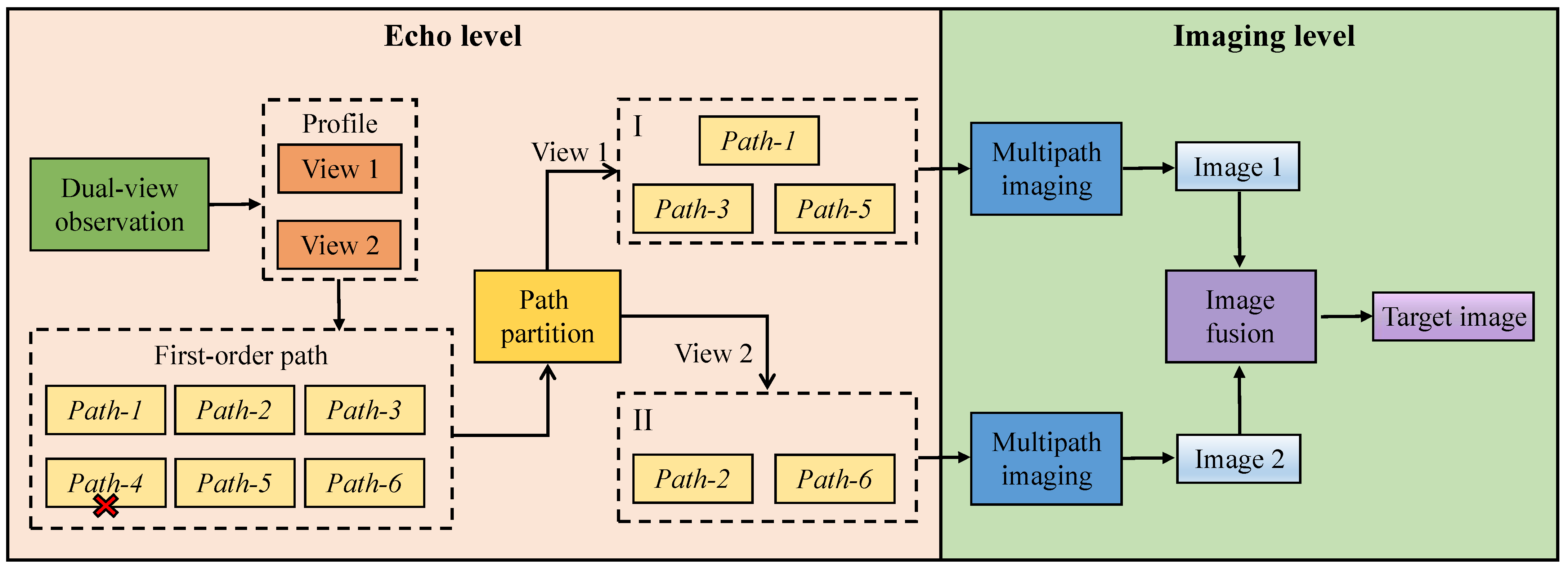
4. Proposed Method
Given the two factors summarized, a method based on dual view and path partition is proposed to suppress ghosts. To facilitate the understanding and application of the proposed method, the flowchart of the approach is given, as shown in
Figure 6. Specifically, the limitation of the single view is discussed at first and then the utilization of the dual-view is derived to enhance saliency multipaths with pertinence. Subsequently, the paths are partitioned into two parts corresponding to the view to fully utilize the enhanced paths. After analyzing the demonstration of imaging results from two views, image fusion is proposed to eliminate ghosts. The algorithms of multipath imaging of single-view and image fusion of dual-view are eventually described.
4.1. Energy Redistribution via Dual-View
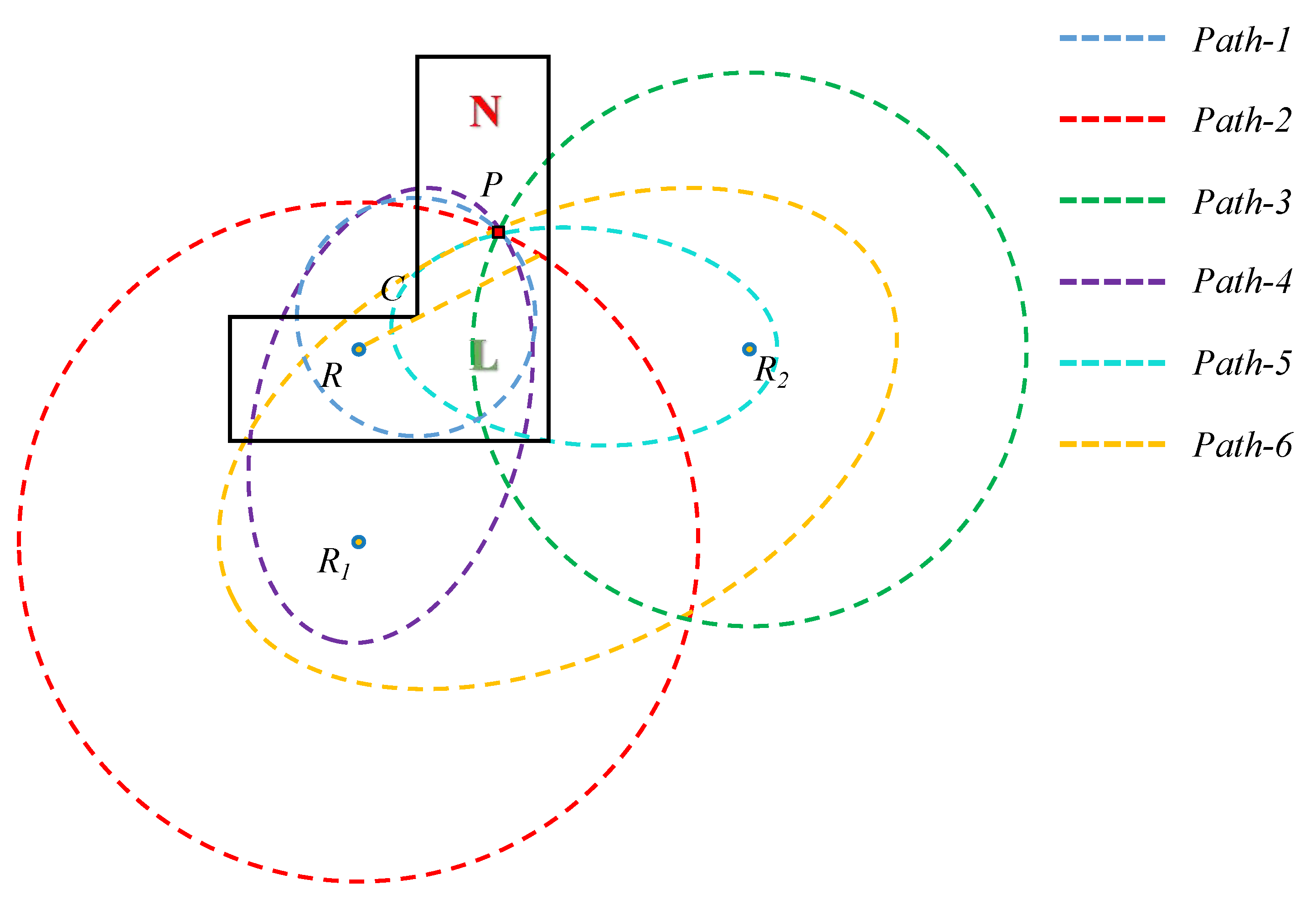
Path energy is closely related to radar beam. Due to the directivity of the radar beam, the energy of emitted signals varies in different directions. Specifically, when the radar is positioned in a space with antenna toward the corner as a single view (View 1) in
Figure 7a, the main lobe is in the direction of the corner and right wall (Wall-4) and the sidelobe directs to the lower wall (Wall-3). Hence, the origin energy of the diffraction and the Wall-4 reflection are stronger but the Wall-3 reflection energy is relatively weak. In other words, the weaker Wall-3 reflection is prone to produce a weak path, which impairs the advantage of the selected saliency path. Thus, it can be concluded that the utilization efficiency of the selected saliency paths decreases for the directivity of the radar beam when performing single-view observation.
The directivity of radar beam causes the energy of Wall-3 reflection to be feeble, but it also induces high reinforcement to the energy of the path corresponding to main lobe. Based on this, we propose to employ a new view to enhance the energy of the Wall-3 reflection with respect to the sidelobe, as shown in
Figure 7b. In this view, the main lobe is turned toward Wall-3 by rotating the radar for enhancing the energy of the Wall-3 reflection, which is initially weak in View 1. Notably, the reinforced path corresponding to the main lobe in one view is also the weak path corresponding to the sidelobe in the other view. Accordingly, the previous view (View 1) and the additional view (View 2) are exploited jointly in the form of a dual-view rather than a single-view, for mutually compensating the weak path energy. Specifically, in View 1, the radar is placed in the original direction, namely towards the corner
C and also in the direction of Wall-3 (see
Figure 7a). Then, the radar is rotated to turn it in View 2, namely toward Wall-2 (see
Figure 7b). In View 1, the energy of diffraction and Wall-4 reflection with respect to main lobe is strong. Likewise, the Wall-3 reflection energy is strong in View 2. In this way, the path energy is redistributed through the new view, thereby enhancing the saliency paths from two views.
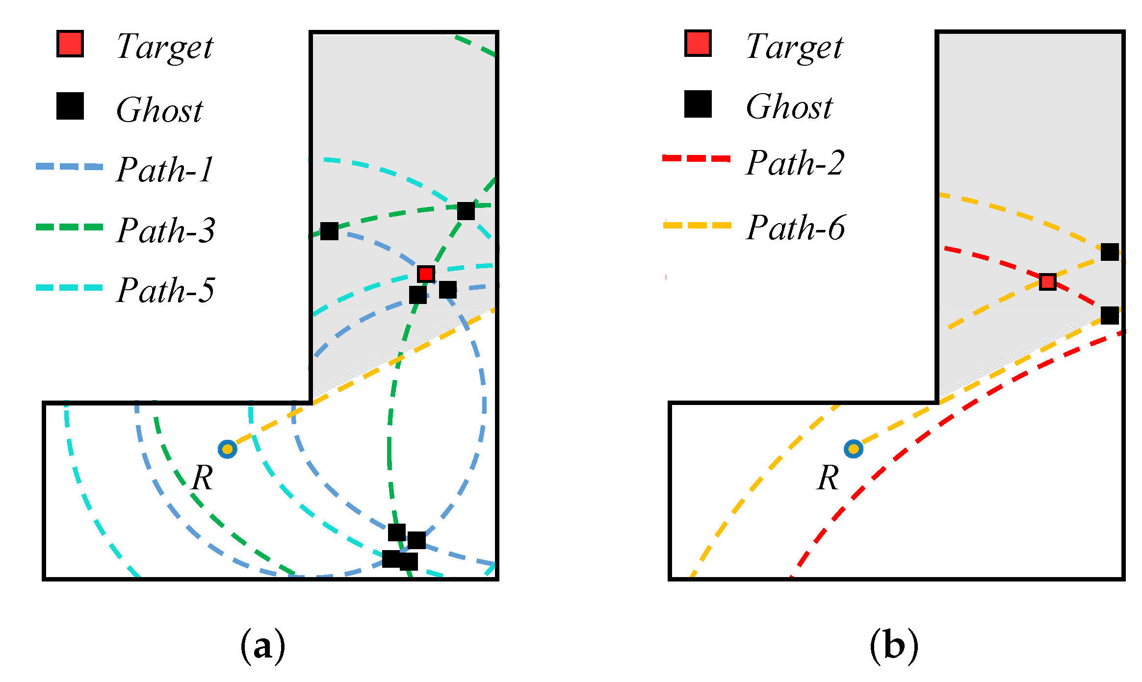
4.2. Path Partition
For the six saliency paths, the energies of these paths are not induced uniform enhancement by dual-view observation, but are strengthened, respectively, in each view. Thus, to further exploit the advantages of the dual-view, a pertinent partition of the path is conducted before multipath imaging. In brief, only the enhanced paths are picked out for imaging to make these strong paths as beneficial as possible to target formation rather than producing ghosts. In terms of View 1, it is a special view because it enhances both the diffraction and Wall-4 reflection. Based on this feature, the pure paths of diffraction and Wall-3 reflection (, ) and the mixed path of them () are exploited as a focusing path for imaging, and the other paths of the selected paths are abandoned. Similarly, the enhanced paths are utilized to perform the multipath imaging in View 2. The difference is that the main lobe only strengthens the Wall-3 reflection in View 2. Therefore, the enhancement is not as high as View 1, but the paths related to Wall-3 reflection are still strengthened, and they are the remainder of the selected paths. However, the diffraction wave of this view originates from the lower sidelobe of the emitted signal, which suggests that the related path is not robust. Hence is disused; namely, the focusing paths of View 2 are and , eventually.
Since the original six-path imaging has now become a three-path and two-path imaging, the aggregation of ghosts is decreased. If multipath imaging is performed by the paths of the two parts, respectively, the demonstration of imaging results from two views can be obtained, which are shown in
Figure 8. In each figure, the red square denotes the target point, while the black square represents the ghost spot. It notices that even only strong saliency paths are applied for imaging, ghosts can still form. However, benefiting from path partition, there are fewer ghosts produced by the overlap of a lesser amount of paths in each view. Moreover, since the focusing paths of the two parts are different, the position of most ghosts in the two images are staggered. On this basis, image multiplication fusion can be utilized to eliminate the staggered ghosts.
4.3. Single-View Multipath Imaging and Dual-View Image Fusion
Multiplication fusion is applied to fuse the images formed from the dual view. By means of this approach, the target points are self-integrated and retained, while the ghost spots are fused and annihilated with the blank portion of the image. In this way, numerous ghosts can be eliminated while the targets are merged. In the following content, the algorithm of the image fusion will be described.
Before image fusion, BP imaging must be completed to obtain the corresponding imaging matrix of two images. The distance of each pixel to the radar according to the corresponding path can be obtained via Equation (
1)
where
represents the distance matrix corresponding to different paths.
Based on the signal model in Equation (
2), the collected radar echo is preprocessed to obtain the range profile matrix with clutter reduction. To elaborate the imaging algorithm, the content of preprocessing is omitted here. Since the imaging result describes the localization at a certain time, only one period of the range profile matrix is needed for imaging. According to the value of each pixel in the distance matrix, the corresponding amplitude is indexed in the range profile
as the image value of this pixel, which is expressed as
where
represents the imaging matrix corresponding to the saliency path. Based on the proposed method, the saliency paths corresponding to each view are utilized to perform multipath imaging, respectively. Thus, in the View 1, the image
is yielded by the incoherent addition of
. Likewise, the image
is obtained by the incoherent addition of
in View 2, which can be expressed as
When the two images are generated directly, ghosts exist in each generated image because of the deficiency of imaging paths and the presence of non-imaging paths. However, the distribution of ghosts is different and the target position is almost invariant in the two images. Thus, we fuse the two images utilizing the multiplication fusion method [
31] for the final image with the suppressing ghost, which can be calculated by
where ⊙ denotes the Hadamard product. On the basis of image fusion, the final image
will eventually contain a noticeable real target with a clear background.
5. Experimental Results
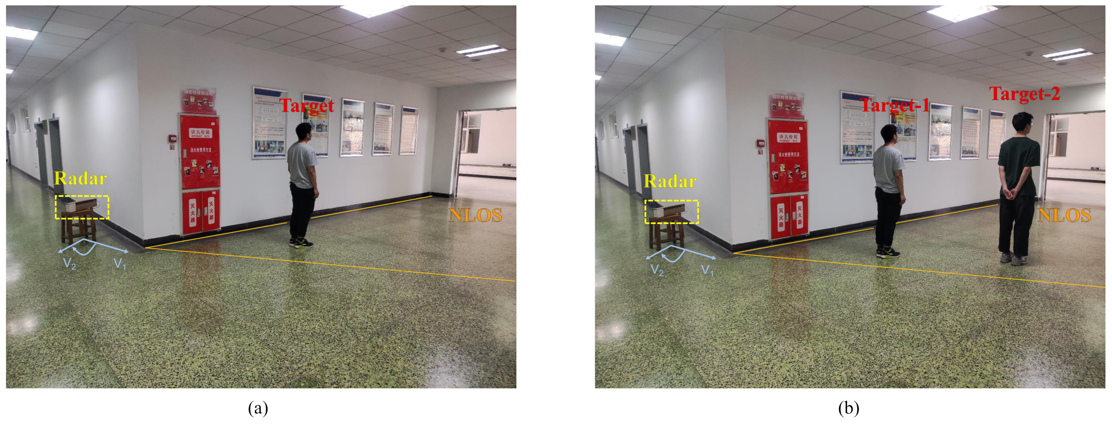
To evaluate the performance of the method in a real urban environment, single-target and double-target detection experiments are carried out respectively in a building, which is shown in
Figure 9. A single-channel UWB radar, which transmits the step frequency modulation wave (SFCW), is employed in this experiment. The detailed parameters of the radar are given in
Table 2. The experimental scenario in
Figure 9 is an L-shaped corridor, and the whole scene is about 8 m × 8 m. The architectural composition can be obtained by other auxiliary tools [
32], thus the rough layout of the environment is known as a priori information. To ensure that the scene resolution is less than the range resolution, the scenario is divided into 512 × 512. Note that the left end of Wall-3 is the origin
O, and the position of corner
C is (2.1 m, 2.35 m). The length of Wall-3 along the horizontal direction is 6.6 m. Similarly, the location of the central point of the Wall-4 is (6.6 m, 4 m), and the length along the vertical direction is 8 m. The targets stand in the NLOS region. When the radar collects data, there are only target personnel in the scene.
5.1. Preprocessing
Before imaging, the
N periods of echo data collected by the radar should be preprocessed to obtain the range profile. The IQ digital signals are combined into complex signals at first. Then, to reduce energy leakage and suppress sidelobes, a hamming window is added to the echo signal [
33]. Finally, FFT is used for pulse compression to generate the range profile [
34]. After that, the above operations are repeated in each period to obtain a two-dimensional range profile matrix with the period as row and range as column.
In the actual scenario of NLOS target detection, the direct coupling signals between the radar transceiver antenna and the wall echo are strong static clutter, which will cover the moving target echo and make it difficult to recognize the human target in the range profile. Since the wall is motionless, the amplitude and the range of the static clutter is stable in different periods. However, the human target is dynamic. Breathing, heartbeat and other parameters of subtle variation of human body that can be detected by UWB radar make the amplitude of the multipath echo periodically change [
35]. For this reason, the moving target indicator (MTI) can be used to restrain the static clutter [
36]. Specifically, the range profile
after filtering the static clutter can be obtained by subtracting the mean value of all of the periods from each period, which can be expressed as
where
N and
M denote the number of acquisition periods and Fourier transform points, respectively. The filtered range profile will be directly utilized for multipath imaging.
5.2. Experiment in Real Urban Scenes
5.2.1. Single Micro-Motion Target
The simple single target scenario is tested first. The radar is located at (1.23 m, 1.72 m) and the target stands on the position of (3.30 m, 3.80 m). Radar is facing the corner in View 1, and in the direction of the lower wall in View 2, which is a clockwise rotation of 90° of View 1. Keeping the radar position unchanged, 400 periods of data are collected from two views. During the acquisition process, the target keeps slightly shaking, and the shaking amplitude is 5 to 10 cm.
Figure 10 shows the range profiles of 400 periods from two views, wherein
Figure 10a is the range profile of View 1, and
Figure 10b is the range profile of View 2. By comparing the range profile of two views, it can be observed that the new view does shift strong energy to the path corresponding to the sidelobe. However, in
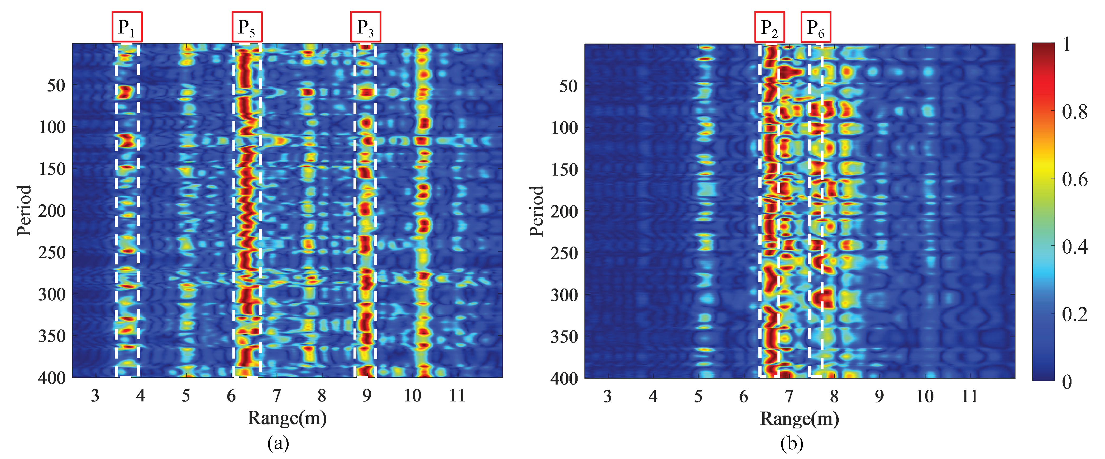
Figure 10b, the paths in the strong energy region are dense, and there is a certain overlap between them. Additionally, there are other high-order strong paths in the two range profiles except the first-order paths. Although the problem of strong high-order paths and path overlap still exists in the two images, the strong paths in the two range images appear in accordance with our expectations, namely, the
(
),
(
) and
(
) in View 1 exhibit strong energy, and the
(
) and
(
) in View 2 similarly show strong energy.
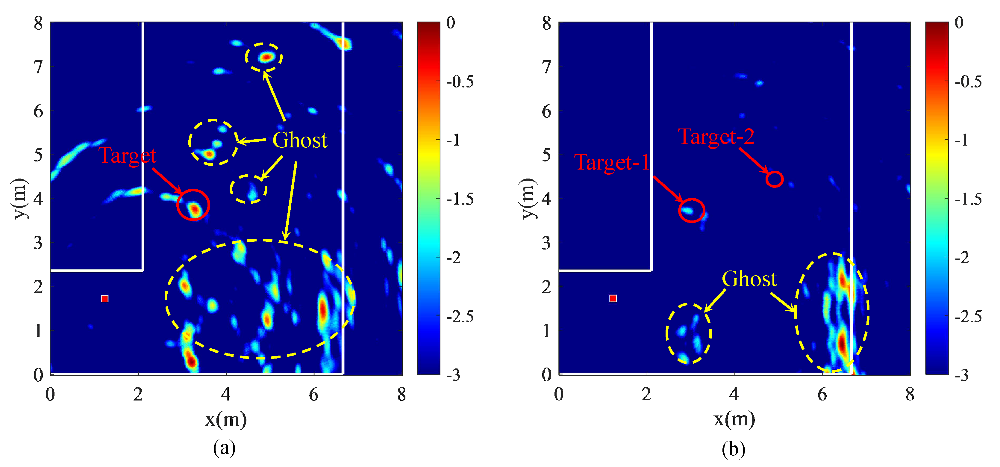
Based on the range profiles from two views, multipath images are produced by using the proposed algorithm.
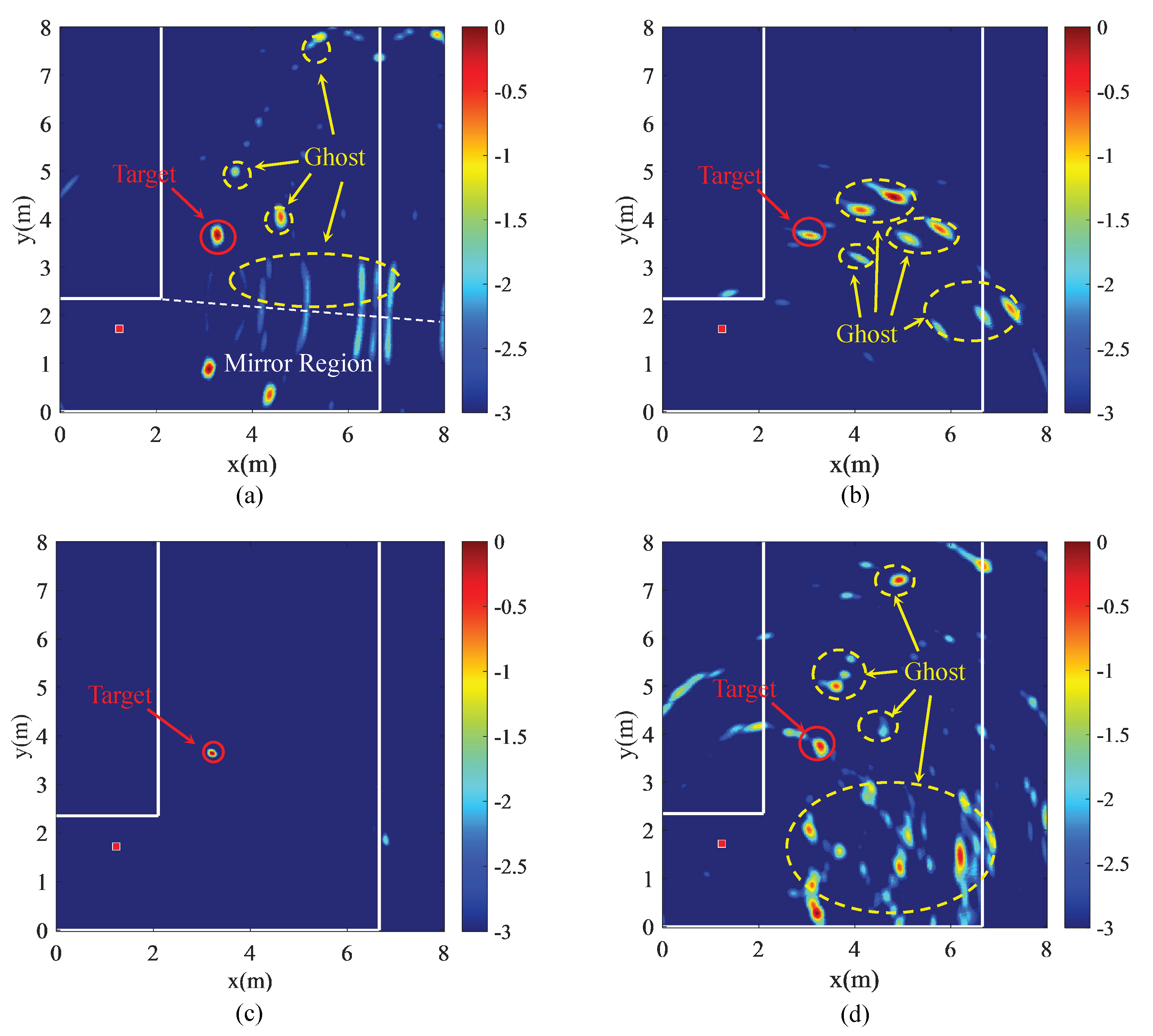
Figure 11a,b show the imaging results of the two views, respectively.
Figure 11c is the fusion result of the imaging results of the two views. In addition, the result of direct multipath imaging is given in
Figure 11d. As can be observed from
Figure 11a,b, ghosts with different energies appear besides the target point, and some ghosts are even stronger than the target. However, there are less ghosts by comparing with
Figure 11d. Moreover, the ghosts in
Figure 11a,b are mainly manifested as points rather than areas, such as
Figure 11d, which prevents ghosts from overlapping. In addition, the distribution of ghost spots between
Figure 11a,b is obviously different. The ghosts in
Figure 11a are scattered, while the ghosts in
Figure 11b are rather concentrated, and there is almost no ghost with overlapping positions between the two images. For this reason, the ghost spots in the L-shaped corridor are almost completely eliminated in the fusion results, and only the target is residual.
Under the effect of image fusion, the final target is the intersection of the target points with respect to the two views. The maximum energy of the target is recorded as the target position, which is (3.21 m, 3.64 m), and the corresponding localization error is 0.184 m.
5.2.2. Double Micro-Motion Targets
To further inspect the performance of the dual-view imaging method in a more complex situation, we perform an experiment in a double target scenario. The radar is located at (1.23 m, 1.72 m). Two targets are located at (3.30 m, 3.70 m) and (4.40 m, 4.30 m) in the NLOS area, respectively. Other conditions are the same as a single target experiment.
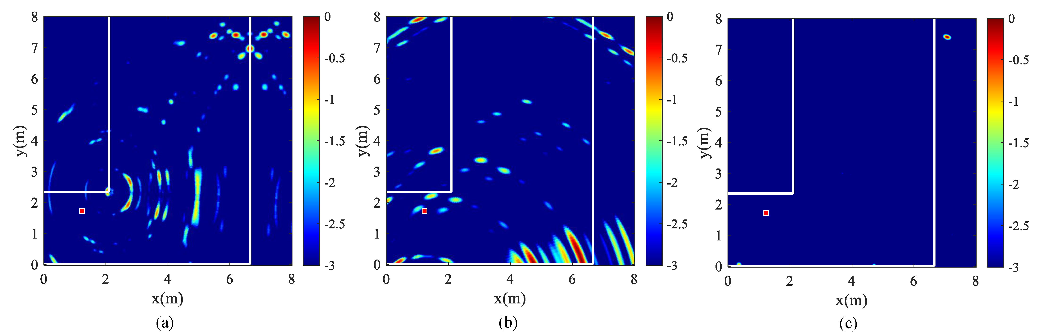
Figure 12 shows the range profiles of two targets from two views.
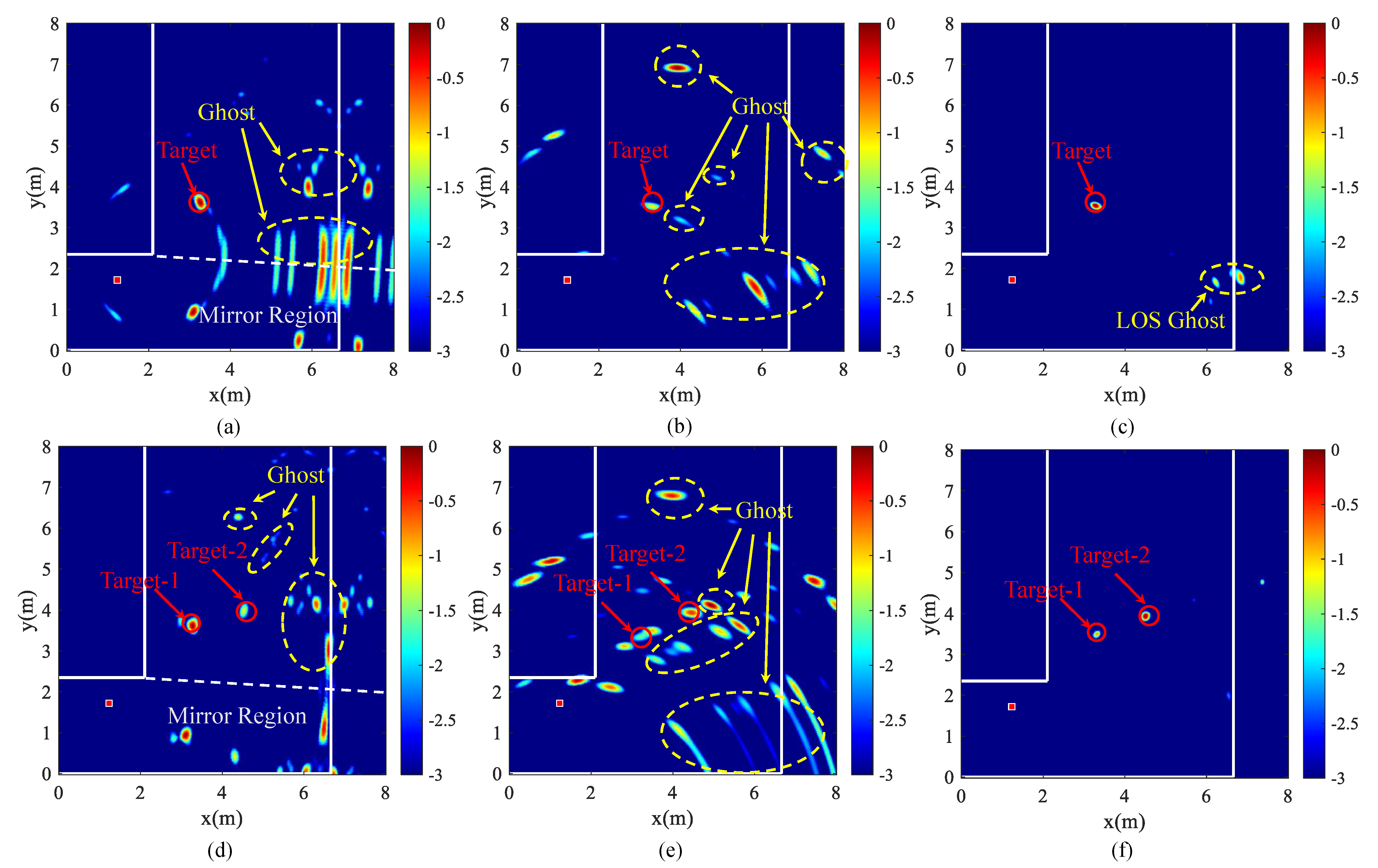
Figure 13a–c show the imaging results of View 1 and View 2, and the fusion of them in the case of double target, respectively. The imaging result of direct multipath imaging is shown in
Figure 13d. Different from
Figure 10, path overlap is more distinct in
Figure 12 due to more multipaths in the case of the double target. However, the path energies of both targets are enhanced by dual-view observation. Compared with
Figure 3b, the corresponding path of target-2 is obviously highlighted, resulting in the presence of the target point in dual-view imaging results (see
Figure 13a,b). Likewise, target-1 also transforms into a strong point in
Figure 13c, rather than a feeble spot in
Figure 13d. In addition, it is observed from
Figure 13a,b that ghost distribution in each view of the double target is very different from that of the single target in
Figure 11a,b. On the one hand, the added target brings more ghosts, which increases the number of ghosts in the scene. On the other hand, due to the mutual interference between targets, the energy of the ghost is changed. Thus, some obvious ghosts in the single target scenario are likely to disappear in the double target scenario, and vice versa. These two reasons jointly affect the display of ghosts.
Meanwhile, in
Figure 13a,b, some ghosts are scattered around the targets, owing to the overlap caused by the contiguous path. However, this phenomenon is not so serious that the ghost and the target merge with each other. Moreover, many ghosts are staggered between the two views, so that they can be successfully removed in the process of image fusion. In comparison with the result of direct multipath imaging in
Figure 13d, the ghosts are greatly suppressed and the disappeared target-2 reappears in
Figure 13c. Although there are still some strong ghosts remained in the LOS region due to the same position in two views, it has little influence for target extraction in the clean NLOS region.
The extracted positions of the two targets are (3.31 m, 3.35 m) and (4.33 m, 4.15 m), respectively. The localization errors are 0.350 m and 0.166 m with respect to the two targets. The experimental results reveal that the dual-view observation is effective in eliminating ghosts and has a positive performance even in the condition of two targets.
5.2.3. Robustness Validation
To substantiate the robustness and applicability of the proposed method, two sets of experiments are carried out. The experimental environment is consistent. The radar is still placed at (1.23 m, 1.72 m).
First, the proposed method is applied to a targetless scene to examine the suppression effect of the proposed method on ghosts caused by environmental clutter. The imaging results are demonstrated in
Figure 14. In this case, the received returns mainly include spatial clutter and noise, which have relatively small difference in energy. Accordingly, in
Figure 14a,b, visible ghosts permeate in the scene. However, due to the constraint of the observation view and the imaging path, ghosts between the two views still remain staggered to a certain extent. Hence, ghosts can be significantly suppressed after image fusion in
Figure 14c. Although there are still ghosts remaining in some areas, the imaging quality has been improved overall.
In addition, we adjust View 2 and retest in the single and double target scenarios. View 2 is replaced by View 3, which is formed by rotating View 1 by about 45°. After the processing of the proposed method, the results are obtained in
Figure 15. In the case of a single target, the energy of target under View 3 in
Figure 15b is weaker compared to View 2. However, the target is still a visible point. In the case of a double target, target-2 is more energetic and target-1 is relative weaker. It is evident that the sensitive detection area shifts with the change of observation angle. However, the ghost distribution between the two views is still very different, which is reflected in both the single target and double target case. Therefore, the results after performing image fusion are favorable.
6. Discussion
In the NLOS detection of urban environment, the NLOS localization based on multipath requires high-quality echo signal, otherwise it is prone to generating a ghost. By using the method of dual-view observation, ghosts are suppressed and a superior imaging result is obtained. In the experiments, there are actually two sets of comparisons to verify the effectiveness of the method. One is the comparison between single and double target, and the other is the comparison between the original method and the proposed method. The range profiles in the result (
Figure 10 and
Figure 12) demonstrate that the dual-view detection method strengthens some first-order paths, which presents weak energy in single-view. Although there are other strong paths in range profiles, the selected paths are manifested as strong paths, even in the double-target scenario. However, the strong high-order paths in the range profile intensify the ghost formation, and the multipath overlap also causes the ghost to appear around the target (
Figure 11a,b and
Figure 13a,b). Fortunately, the selected saliency paths are divided according to the dual-view, so in the imaging results, the targets are highlighted. Especially in the case of double target, the problem of target-2 loss caused by direct multipath imaging is ameliorated, and target-1 is greatly strengthened. [From the imaging results of the method in previous research [
28], it can be observed that ghosts are prone to merging into a region (
Figure 11d and
Figure 13d). In contrast, the path partition in the proposed method reduces the accumulation of ghosts, making it easier for ghosts to stagger rather than merge with each other.
On the whole, judging from the final imaging result, our approach has prominent improvement in target highlighting and ghost suppression. The problem of targets being covered by ghosts in the previous method is solved. Experimental results also indicate that the method is still applicable under the circumstances of interference and multipath energy loss. Nevertheless, in terms of positioning accuracy, the proposed method has a certain decline compared to the previous method. Due to the irregular shape of the human body and the roughness of the wall, a certain deviation might occur in the propagation length of the EM wave. Furthermore, the two groups of data are collected at different times, and the position of the target in the micro-motion state changes. These two factors conduce to offset of the target point between the two views. It is slight movement in the single-target case. However, the migration of target-1 is obvious in the dual-target imaging results. This phenomenon can result in the elimination of targets in the procedure of image fusion. Thus, it is necessary to compensate for this to procure more accurate positioning in future work.
In addition, the study in this paper only considers the L-shaped scenario composed of two reflective walls. Actually, the L-shaped corner consisting of single reflective wall is common as a NLOS scenario. For instance, if there is no lower wall (Wall-3), View 2 that depends on this reflective wall is inapplicable, as well as the corresponding multipaths. However, from the perspective of observation, a new view can be created by changing the angle of radar toward the remaining reflective wall. However, this operation will be mainly manifested in the energy difference of multipaths between the two views, which means that the use of high-order reflections and radar with higher resolution are required to present this difference more clearly. This circumstance will be taken into account in the future research. Moreover, the method will be extended to a further experimental analysis of other urban NLOS environments (such as the T-shaped scenario and cross-shaped scenario).
7. Conclusions
In summary, to obtain better detection results in the NLOS region of urban environment, an imaging method of NLOS targets based on a dual-view observation has been proposed in this paper. Based on a multipath imaging algorithm and propagation model, three phenomena of path ambiguity in a range profile and their influence on imaging results are analyzed. The analysis reveals that increasing the strong selected paths and reducing the accumulation of ghosts are two keys to suppress the ghost. Focusing on these two critical factors, we mainly implement ghost suppression at two levels. From the level of radar echo, based on the directivity of the radar beam, a new view is created by rotating the radar toward another reflective wall. The weak selected paths in the original view are highlighted in the new view. Thus, we jointly utilize the two views to increase the amount of strong selected paths. On the basis of a dual-view, the selected paths are partitioned into distinct parts related to each view, which maximizes the utilization efficiency of the paths and reduces the aggregation of ghosts. At the imaging level, the image fusion method is implemented to suppress the ghosts due to the different distribution of ghosts in the two views. The experimental results demonstrate that, compared with direct multipath imaging in a single-view observation, the proposed method can effectively eliminate most ghosts, optimizing the imaging result.
There are still some limitations in the proposed approach. It can be observed from the experimental results that the position deviation of the target induces the improvement of the positioning error. Hence, it is necessary to compensate for this deviation. Moreover, the effective detection area of diffraction and first-order reflection is limited. When the target exists in a farther region, high-order paths are required for precise positioning. In addition, we need to conduct more experiments on various NLOS scenarios to cope with a complex urban environment. Therefore, further research will focus on these problems to improve applicability and localization accuracy.


