Abstract
At present, 5G base stations are densely distributed in major cities based on improving user concentrations and the large demand for services in urban hotspot areas. Moreover, 5G communication requires more accurate communication propagation loss (PL) monitoring. Low-build areas, such as suburbs and rural areas, are prone to forming relatively stable tropospheric ducts, which can bend the signal to the surface in the duct-trapping layer for multiple reflections. Due to the random flow of the atmospheric air mass, each reflection of the communication signal is re-scattered in the troposphere through the top of the duct layer, thereby expanding the propagation range of the signal and changing the expected effect of radio wave propagation. If ducting and troposcatter effects happen in the 5G base station antenna layer, co-channel interference (CCI) could occur, affecting the quality of electromagnetic propagation. Urban links in the plain area have no major terrain obstacles, but ground fluctuations and land cover scattering have a greater impact on the signal scattering at the bottom of the duct. On the basis of the forward-propagation theory, this paper adds factors, such as ducting the forecast value using real weather parameters, terrain, and land cover-type distributions to evaluate the CCIs of over-the-horizon communications on the intercity link. Based on 1300 sets of randomly generated terrains and landforms, two deep learning (DL) models were used to predict the PL of over-the-horizon communications between cities in a land-based ducting environment. The accuracy of LSTM prediction could reach 98.4%. The verification of PL prediction using DL in this paper allows for quick and efficient prediction of PL in the land-based ducting of intercity links using land cover characteristics.
1. Introduction
The fifth-generation (5G) wireless system is in the rapid development stage of China’s mobile telecommunication standards. Moreover, 5G relies on unique advantages, such as high speed, low latency, large capacity, and wide connectivity to rapidly integrate applications in various fields of production and life, and its application scope will eventually range from mobile broadband services to next-generation car and device networking services [1]. Meanwhile, in the sixth-generation mobile communication technology planning, satellite internet communication will play an important role in realizing the transition from the interconnection of everything to the intelligent connection of everything. With the rapid development of coastal cities, the surrounding sea–land junction meteorological environment and the distribution of ground objects will change and become more complex. The modeling requirements for the forward-propagation of communication signals when mixed ducts and non-uniform turbulence occur are more accurate.
The 5G network must coordinate high, medium, and low frequencies according to user service coverage and speed requirements to form an efficient and coordinated layered coverage. According to public data, by the end of 2020, operators have opened a total of 718,000 5G base stations, and the number of 5G mobile terminal connections has exceeded 200 million. The dense distribution of base stations has higher requirements for accurate reception and anti-interference of communication links. We selected three sub-6 GHz in the 5G plan for the simulation, and evaluated the weather-induced intercity CCI that may have occurred in different urban links when ducts and tropospheric turbulence existed.
An atmospheric duct is mainly caused by the increase of atmospheric temperature with the increase of altitude or the rapid decrease of water vapor density with the increase of altitude. Turton [2] proposed five synoptic processes that can form atmospheric ducts—radiative temperature inversion, subsidence temperature inversion on land surface, temperature advection inversion at the sea–land interface, topographic inversion in local valleys, and frontal temperature inversion are prone to occur. According to data statistics, communication disconnections and other phenomena often occur at night after rain in the plains of China. The monitoring found that it was related to the interference of ducts. This paper selected urban links in the East China Plain (where ducts are prone to occur) to analyze the CCI of over-the-horizon communications.
In 1946, Leontovich and Fock [3] proposed a forward full-wave analytical method—the parabolic equation (PE) method—to solve the problem of forward-propagation in vertically layered inhomogeneous tropospheric ducts. In 1973, Hardin and Tappert [4] developed a split-step Fourier transform (SSFT) algorithm suitable for underwater acoustic transmission to solve parabolic equations. Subsequently, the PE model has been theoretically deduced and optimized by a series of scholars. Based on its framework, the Feit–Fleck wide-angle parabolic equation (WAPE) [5] method that can calculate a larger range of grazing angles was proposed. The grazing angle can reach 30°. In 1983, Thomson and Chapman [6] formally proposed a new WAPE form based on the Feit–Fleck method, and Kuttler [7] verified the good performance of WAPE at wide elevation angles.
The PE method takes into account the refraction and diffraction effects of radio wave propagation. Moreover, it can simply and accurately describe the dielectric parameters of the irregular surface and the refractive index distribution of non-uniform atmospheric structures to simulate the propagation characteristics of radio waves in a complex environment. The step-by-step iterative solution method can predict the propagation loss of point-to-point links, and can further realize regional propagation loss prediction. In 2000, Levy [8] made a relatively complete summary of the derivation, terrain, and boundaries of electromagnetic wave propagation calculated by the parabolic equation method, and preliminarily deduced the three-dimensional parabolic equation algorithm. In 2003, Janaswamy [9] used 3D vector parabolic equations to predict path loss on flat terrain with buildings. In 2005, Hu et al. [10] established a macrocell radio propagation model for mobile communication based on 3DPE. In 2019, Rasool et al. [11] deduced the solution of 3DPE, and used 3DPE for field strength prediction for flat and irregular forest environments. In this paper, the PE model was improved to simulate the possible CCI of the over-the-horizon transmission of the communication signal on the intercity link.
When electromagnetic waves encounter irregular terrain during transmission, such as wedge-shaped boundaries, more intense reflection will occur, so the modeling of complex terrain is also particularly important. In 1987, Dockery and Konstanzer [12] first used PE for tropospheric wave propagation problems. In 1996, Kuttler and Dockery [13,14] proposed the method of continuous hybrid Fourier transform under the impedance boundary to solve PE, which greatly improved the efficiency of the SSFT algorithm. In 2000, Donohue and Kuttler [15] applied the SSFT PE algorithm to irregular terrain, extended the terrain shift map algorithm proposed by Beilis and Tappert to WAPE, and deduced a new impedance boundary condition for electromagnetic wave incidents on the surface of a finite conductor, such that the WAPE solution could be adapted to the previous MFT algorithm. Numerical examples demonstrate its effectiveness on impedance surfaces with terrain slopes of 10–15° and discontinuous slope changes of 15–20°. To accommodate terrains with larger slopes, it is recommended to combine the terrain shift map with terrain masking (knife-edge diffraction) approximations. In this paper, the WAPE-based terrain shift map algorithm and the new impedance formula are applied to the real inter-city link distribution to evaluate the atmospheric loss distribution.
Since the influence of troposcatter cannot be ignored, scholars have begun to turn their focus to the influence of atmospheric ducts on troposcatter communications. In 1993, Hitney [16] proposed the scattering parabolic equation method based on the radio physical optics (RPO) model. This method can simply and effectively calculate the tropospheric scattering caused by atmospheric turbulence on the basis of PE. In 2009, Ivanov et al. [17] used this method to further study the boundary layer leakage of tropospheric scattering and the propagation characteristics in evaporation ducts. In 2013, Wang et al. [18] carried out experiments with three unequal-distance cross-sea circuits to study the signal fading characteristics of tropospheric scattering in the sea area where evaporation ducts occur. The evaporation duct phenomenon was found to significantly alter the fading level of the signal.
In 2015, Song et al. [19] found that the atmospheric meteorological state has a great influence on the scattering loss through the study of the scattering parabolic equation. In 2016, Wanger et al. [20] evaluated the refractive index of the lower atmosphere and gave a propagation loss (PL) measurement; that is, using height-independent PL measurements over a range of 10–80 km to infer information about the existence and potential parameters of atmospheric ducts in the lowest 1 km of the atmosphere. Its main improvement includes turbulence-induced distance-dependent fluctuations in the forward-propagation model, where the inhomogeneous turbulence model uses parameters that are height-dependent on the mixing ducts. In this paper, Hitney’s RPO basic scattering model was applied to the transmission over inter-city links with evaporation ducts, and the non-uniform turbulence model proposed by Wanger was used for transmission calculations over inter-city links with mixed ducts.
In this paper, combined with open source data from multiple sources, the probability of occurrence of ducts in the selected area was verified by WRF. The land types in inter-city links were extracted based on MCD12Q1 from MODIS. The empirical values of complex dielectric parameters suitable for these land types were found from various references or measured values. In the end, we substituted impedance correction, real terrain relief, and turbulence correction into intercity links to evaluate the probability of possible interference when ducts and turbulence occurred between different cities.
2. A Multi-Source Real Data Model for Intercity Link Communication Propagation Computing
2.1. WRF Models Regional Duct Distribution
The new generation of the mesoscale advanced research WRF model system is a flexible and advanced atmospheric simulation system. It is suitable for a wide range of electromagnetic applications from meters to thousands of kilometers. The WRF modeling system is shown in Figure 1 and mainly consists of the following main programs: 1. WRF pre-processing system (WPS); 2. WRF data assimilation (WRF-DA) assimilation system; 3. advanced research WRF (ARW) solver; 4. post-processing and visualization tools.
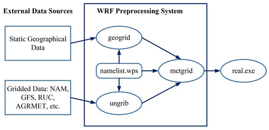
Figure 1.
Procedures of the WRF pre-processing system.
We used the WRF pre-processing system (WPS) to specify the static terrain data path of the processing area and perform interpolation on the terrain data (including terrain, land use, and soil type). The background field and boundary field data used in WPS were NCEP FNL (final) business global analysis data [21,22]. The global meteorological data in GRIB2 (Gridded Binary2) format were downloaded. The grid data resolution was 1° × 1° and the time interval was 6 h.
The latitude and longitude coordinate ranged of the selected area were (25.846°N–36.224°N, 117.472°E–123.528°E). We set the number of coarse grids and fine grids, and their relative positions. There were several cities that we simulated in the fine grids, of which, the latitude and longitude coordinates were Wuxi (120.3166°E, 31.5072°N), Hangzhou (120.1602°E, 30.2856°N), Nanjing (118.7988°E, 32.0651°N), Shanghai (121.4802°E, 31.2389°N), and Jiaxing (120.7635°E, 30.7509°N), respectively. Using the Lambert conformal projection, the simulation area was used as a coarse grid, and the key selected urban area was a fine grid. The schematic diagram of the simulation area is shown in Figure 2, and the parameter settings are shown in Table 1. After the initialization parameters were set, we executed geogrid.exe to define the model domain to be processed, and imported the static terrain data into the grid; secondly, we commanded ungrib.exe to extract the meteorological fields from the imported grid-formatted terrain fields; finally, we executed metgrid.exe to horizontally interpolate the meteorological fields extracted by ungrib.exe in the second step into the grid model defined by geogrid.exe in the first step. The vertical interpolation of the meteorological field to the WRF eta level was realized in the actual program.

Figure 2.
The nested grids of the simulated areas in WRF modes.

Table 1.
Parameter settings of the WRF numerical simulation.
The background field data of 1 March 2018, 1 June 2018, 1 September 2018, and 1 December 2018UTC were selected, respectively, to simulate the duct distribution in the selected plain area by seasons. The duct distribution located in East China is shown in Figure 3.
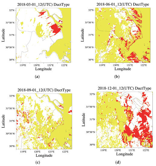
Figure 3.
The distribution of ducts in selected plain areas by seasons, where the yellow area represents the surface duct and the red area represents tge elevated duct. (a) March. (b) June. (c) September. (d) December.
As shown in Figure 3, it can be seen that the ducts were distributed in the sea area throughout the year, while the inland ducts were less distributed and scattered in March. The inland ducts were densely distributed in June and December, and the inland ducts were also widely distributed in September, but not continuous. Due to the large amount of data to be analyzed in the selected area, only the first day of each quarter was selected for numerical simulation. The actual occurrence of the duct was also related to sudden changes in weather, such as rainfall and snowfall, or the diurnal temperature variation. However, based on the numerical simulation results of WRF in the East China Plain, it is fully proven that the ducting phenomenon occurs in this area all year around. Therefore, the surface duct with the base layer is used to evaluated the CCI of the intercity in East China.
Figure 4 and Figure 5—we calculated the duct height and duct intensity distributions on 1 June and 1 December 2018 using WRF mesoscale numerical modeling software.
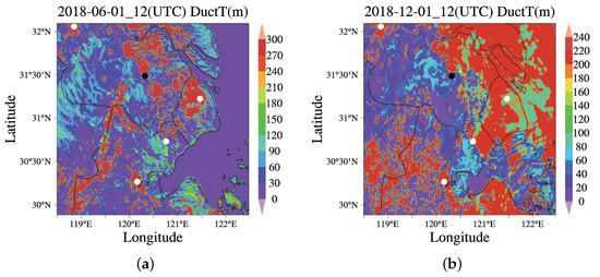
Figure 4.
Duct height (m) calculated by WRF on 1 June and 1 December 2018. (a) Duct height (m) on 1 June 2018. (b) Duct height (m) on 1 December 2018.

Figure 5.
Duct Strength (M-units) calculated by WRF on 1 June and 1 December 2018. (a) Duct strength (M-units) on 1 June 2018. (b) Duct strength (M-units) on 1 December 2018.
As shown in Figure 4, the average distribution of duct strengths between cities in June is more than 60 m, the intercity link from Shanghai, Jiaxing, to Wuxi also has a hybrid duct phenomenon of up to 240 m, and its strength can reach up to 35 M-units or so, which is shown in Figure 5a. In December, the marine ducts in this area were densely distributed, and the heights and strengths of the ducts were significantly higher than those in coastal cities. In inland areas, the duct heights on the Nanjing–Wuxi link were basically distributed at about 40–80 m, while duct heights on the intercity link of Shanghai–Wuxi and Jiaxing–Wuxi could reach more than 200 m; the average duct strength was about 20 M-units. Considering the limitation of the installation height of the communication signal antenna, based on the duct distribution results simulated by the real data using WRF, this paper studied the over-the-horizon transmission of the 5G communication signal on the intercity link when the non-uniform surface-based duct with the trapping layer height was 40–80 m.
2.2. Extraction of Digital Elevation Data on Intercity Link
This paper used DEM digital elevation data with a resolution of 90 m for the analysis and calculation. The data set was provided by geospatial data cloud site, Computer Network Information Center, Chinese Academy of Sciences (http://www.gscloud.cn). We accessed the data in 19 July of 2022. The data came from SRTM (Shuttle Radar Topography Mission) and were jointly measured by the National Aeronautics and Space Administration (NASA) and the National Imagery and Mapping Agency (NIMA).The data volume of radar images acquired by the SRTM system was about 9.8 trillion bytes. After various pre-processing steps, such as editing, gross error removal, determining water surface elevation, and defining coastlines, etc., the results were cut into 15,000 pieces according to geographic coordinates. Each map frame was stored in latitude and longitude, and a digital elevation model (DEM) was made. The data accuracy that could be used for scientific research was the STRM-3 version, which was sampled every 3 arc seconds, and the data of 3 arc seconds were collected and generated from 1 arc second of data. They were divided in of the latitude and longitude grid in the geographic projection, and the horizontal resolution was about 90 m. SRTM terrain data obtained by CIAT (the International Center for Tropical Agriculture) using a new interpolation algorithm, this method better fills the data gap of SRTM 90. The interpolation algorithm is from Reuter et al. [23].
SRTM-3 data are divided into files every 5 degrees of longitude and latitude, with a total grid data of 24 rows (including the area that latitude ranges from 60°N to 60°S), 72 columns (longitude ranged from −180°W to 180°E). According to DEM data product, the elevation data of several intercity links from the area of interest (25.846°N–36.224°N, 117.472°E–123.528°E), could be determined with a resolution of 90 m. Interpolating to fill the null zone, the global elevation distribution of the selected area is obtained as shown in Figure 6.
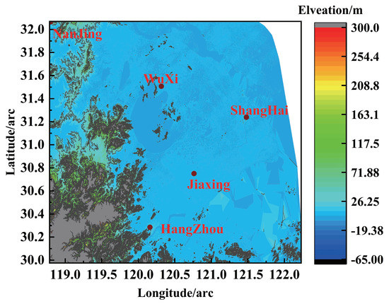
Figure 6.
DEM of the selected area.
We extracted the link elevations from four surrounding cities to city A. Considering that the minimum distance between cities was about 90 km, which was about 0.81° when it was represented by the longitude and latitude coordinates. To not reduce the accuracies of DEM data on intercity links, we extracted the required link DEM data using traversal and interpolation. The processing steps are in Figure 7.

Figure 7.
Flow chart of the extracting line-distributed DEM data from polygon-distributed DEM data.
2.3. Data Extraction of Land Cover Distribution Types of Intercity Links from MODIS
2.3.1. Land Cover Type Distribution on Intercity Links of East China
The MODIS Land cover product MCD12Q1 provides a series of 13 sets of scientific data sets with 500 m of resolution global land cover projections, which were published in an annual span, including five different land cover classification schemes of IGBP/UMD/LAI/BGC/PFT, and a new three-layer classification standard based on the land cover classification system (LCCS) from the Food and Agriculture Organization, including a quality assurance (QA) layer, posterior probability of the LCCS three-layer standard, and binary land water cover. MCD12Q1 was secondary validation datum based on cross-validation of the training dataset generated from projections.
MCD12Q1 was derived from observations from the Terra and Aqua data inputs and was generated using MODIS reflectance data supervised classifications. The primary land cover program identified 17 land cover categories as defined by the International Geosphere–Biosphere Program (IGBP), including 11 natural vegetation categories, 3 developed and planted land categories, and 3 non-vegetated land categories, as listed in Table 2.

Table 2.
IGBP Land Cover Type.
In this paper, the vegetation distribution in the latitude and longitude range areas was converted into WGS84 projection by positive selection projection and expressed in Figure 8:
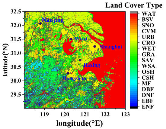
Figure 8.
MCD12Q1-LC1 distribution of the selected region.
We converted the original sinusoidal projection of the MCD12Q1 to WGS84 projections. The original data of MCD12Q1 was tile distribution, which was similar to that of DEM. After converting the projection of MCD12Q1, the original square tile became a diamond distribution. Then the required intercity land type data were extracted from the adjacent converted diamond tile data. The value of the land type of the latitude and longitude of the intercity link was uniformly interpolated according to the equidistant latitude and longitude interval. Finally, we traversed the data coordinates in the shorter dimension direction (longitude direction or latitude direction), found the point closest to the longitude and latitude slope of the link, and performed a one-dimensional intercity link land type on the standard of the IGBP arrangement. The land cover types classified in the IGBP of the links from the four surrounding cities to Wuxi, marked in Figure 8, are shown in Figure 9:
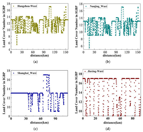
Figure 9.
Land Cover types of IGBP on intercity links from four different cities to Wuxi. (a) LC distribution on Hangzhou–Wuxi. (b) LC distribution on Nanjing–Wuxi. (c) LC distribution on Shanghai–Wuxi. (d) LC distribution on Jiaxing–Wuxi.
2.3.2. Determination of Corresponding Dielectric Parameters in the Area Covered by the Intercity Link
The classification of the IGBP features was relatively fine, and there have been many studies on the empirical model and test results of several kinds of vegetation dielectric permittivities. After consulting a large number of literature studies, we chose to use the test results in the literature to solve the simulation in this paper. The land types involved in several intercity links selected in this paper mainly include: 9 Savannas, 10 grasslands, 11 permanent wetlands, 12 croplands, 13 urban and built-ups, 15 snow and ice, 16 barren or sparsely vegetated, 17 water bodies.
According to [24], we chose the following experimental results: the permittivity of 18.2 + 4.5i of sandy loam from a frequency of 3 GHz and water content of 0.3 g/cm3 as the permittivity of barren or sparsely vegetated; the no. 16 classification in the IGBP land cover (LC) rule. Silty clay in Figure 10 was selected as the no. 11 classification in the IGBP LC rule when the frequency was 1.4 GHz and the water content ; that is, the permittivity of the permanent wetland WET was assumed as 26.5 + 1.2i.
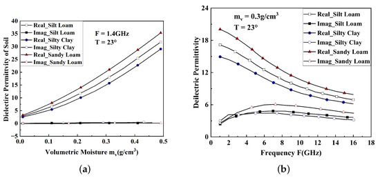
Figure 10.
Dielectric permittivity of wet soil at different volumetric moisture or frequencies. (a) Dielectric constant vs. Volumetric Moisture. (b) Dielectric constant vs. frequency.
By referring to Reference [25], the crops with large soil fertility contribution rates distributed in the selected area (north China region) were mainly rice. The dielectric permittivities of rice leaves of 50 rice growth days of were selected as the permittivities of crops (CRO) in the IGBP classification (i.e., 4.0 + i0.93). Moreover, the permittivity of rice straw grown for 10 days was taken as the permittivity of the savanna (SAV) in IGBP classification, which was 2.85 + i0.33.
According to Reference [26], combined with the test results, the permittivity of asphalt in the oil-generating area was generally ∼15, ∼0.30. Then we chose the dielectric permittivity of the asphalt of the intermediate state as the permittivity of urban and built-up (URB) areas in the IGBP classification, which was 5 + i0.070.
In Reference [27], from the relationship that the complex dielectric permittivity of wet snow versus water content or frequency at natural conditions (as shown in Figure 11), we choose the snow and ice (SNO, 15th classification in IGBP LC) dielectric permittivity 15.8 − i1.8, when the frequency was 3 GHz, the water content was 0.3, and the temperature was −5 °C.
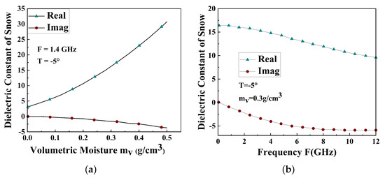
Figure 11.
Dielectric permittivity of snow at different volumetric moisture/frequencies. (a) Dielectric constant vs. Volumetric moisture. (b) Dielectric constant vs. Frequency.
The reference dielectric permittivity values used for the land cover types ultimately involved in this paper are listed in Table 3.

Table 3.
Dielectric constant used on simulated intercity links.
This paper used the WRF database source, MCD12Q1 land cover classification from MODIS, terrain relief from the DEM to model the over-the-horizon propagation of communication signals at a sub-6 frequency band, comprehensively considering atmospheric ducts and tropospheric inhomogeneous turbulence. The schematic diagram of the over-the-horizon propagation of intercity links is shown in Figure 12.
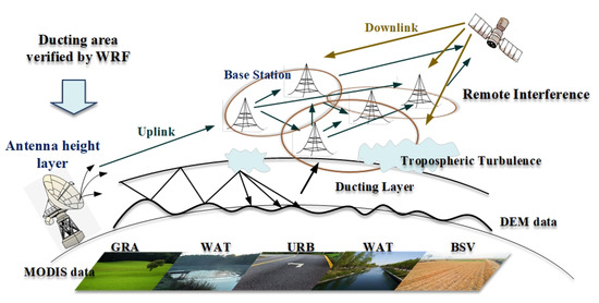
Figure 12.
Schematic diagram of over-the-horizon forward-propagation of intercity links based on multi-source data fusion.
3. Scattering Parabolic Equation Algorithm for Irregular Terrain and Inhomogeneous Turbulent Atmosphere
When 5G signals are transmitted between cities, irregular terrain relief and dielectric roughness exist on the lower boundary of the atmospheric duct. At the same time, there may be non-uniform turbulence in the duct layer and even its upper and lower boundaries. This paper considers the actual situation and studies the radio wave propagation based on the complex meteorological environment when ducting and turbulence occurs. Compared with many existing terrain models, after research and comparison, a wide-angle shift-map (WASM) algorithm was determined in the terrain boundary processing of the WAPE model. The over-the-horizon propagation effects caused by duct considering the irregular terrain, different surface dielectric parameters at the lower boundary, and non-uniform tropospheric turbulence at the upper boundary of the duct layer were simulated on inter-city links. The simulation results were compared with the results of numerical modeling software, AREPS (advanced refractive effects prediction system).
The tropospheric atmosphere uses the refraction index n to describe the refraction characteristics of electromagnetic waves. The propagation of electromagnetic waves on the earth’s surface needs to consider the influence of the earth’s curvature. The atmospheric refraction index n is expressed by the modified refraction index m as
The modified refractive index M is expressed as
When simulating the tropospheric duct propagation, the refractive index profile used a hybrid four-parameter three-line model to represent a hybrid duct with a base layer:
where is the height of the duct base layer and is the duct thickness.
When tropospheric ducts appear over land due to changes in meteorological conditions, the electromagnetic wave wavelength and emission elevation angle satisfy the following conditions:
Maximum cut-off wavelength that can trap the wave in the duct
where is the modified refractive index of the top of the duct trapping layer. When studying the propagation through the duct structure with the base layer, the above formula is simplified as
where t is the duct thickness in m and is the modified refractive index difference corresponding to the duct layer height and the surface.
The critical trapping angle is simplified by derivation using Snell’s law, as:
When the wavelength of the electromagnetic wave was less than the cut-off wavelength, and the emission elevation angle was within the trapping angle, the electromagnetic wave was trapped in the duct and propagated over a long distance beyond the horizon.
In the two-dimensional Cartesian coordinate system, it was assumed that the electromagnetic wave propagated along the x-axis, the electromagnetic field component was independent of the y-axis, the refractive index n of the propagating medium was isotropic, and the field component satisfied the two-dimensional scalar wave equation.
where is the electromagnetic wavenumber in vacuum, is the electronic or magnetic field. for horizontally polarized, and for vertically polarized.
We numerically approximate the wave equation to obtain a wide-angle parabolic equation (WAPE) [5] form suitable for computing irregular terrain
The piecewise linear terrain shift map (PLTSM) algorithm proposed by Donohue and Kuttler was used to model the terrain boundary of the PE propagation model. The D–K algorithm is based on the continuous terrain shift map (CTSM) algorithm of Beilis–Tappert, which improves the difficulty of calculating the terrain curvature data.
The core idea of the PLTSM algorithm is to establish a new coordinate system on the irregular terrain section, and translate the PE calculation of each step into a flat ground form for solution. The terrain translation coordinates are expressed as
Let the field components expressed in the new coordinate system be equal to the field components expressed in the irregular terrain coordinate system . We introduce simplified functions . According to the coordinate map formula and wave equation, the forward-propagation PE considering irregular terrain is obtained
In the piecewise linear terrain, the phase function is . Let , we obtain the WAPE in the coordinate system expressed in terms of the terrain curvature:
In this paper, digital elevation model (DEM) data with 90 m resolution were used, which were downloaded from the National Geospatial data cloud. Taking into account the resolution, it was more accurate to use the terrain slope to calculate the long-distance propagation. To avoid dealing with the terrain curvature directly, the PLTSM method was used. The phase factor is expressed in the form of
Let
where is the undetermined constant. Substituting Equations (11)–(13) into the forward-propagation PE (10) after the coordinate transformation, the simplified approximation of PE can be obtained:
The above equation is the WAPE corresponding to the PLTSM method. We abbreviate this method as TWPE (terrain wide-angle parabolic equation).
The atmospheric refraction profile is expressed using the modified refraction index in Equation (14); Equation (14) is solved by the split-step Fourier transform (SSFT) method. The relationship between the transforming field and the physical field could be expressed as . For the segmented irregular terrain surface, the terrain inflection point changes due to different terrain slopes on adjacent segments, while the phase factor on adjacent segments need to be processed continuously to satisfy the realistic terrain simulation. The required phase correction item when the signal reflects from segment 1 to segment 2 is as follows:
where is the reflection point from segment 1 to segment 2; , where is the angle that the local terrain slop makes with the horizontal. In this modification of the phase factor, this phase item makes the controlling factor of height-dependent sequences of transforming filed expressed by . The controlling angle happens to be the physics angle corresponding to the slope difference across the reflection point . Then when controlling the phase of the transform field, in order to suppress the side lobes on the height sequence, the height step size must satisfy the following condition:
where is the maximum angle of the controlling factor. The limiting condition on the height step size above is much more strict than the Nyquist sampling theorem. Considering the impedance boundary condition suitable for irregular terrain, Donohue and Kuttler deduced the impedance boundary condition on the terrain surface, which PLTSM needs on the basis of the standard Leontovich impedance boundary condition. It is expressed as follows:
where is the Fresnel reflection coefficient, which forms differently according to different polarizations on radio waves. Moreover, , where represents the grazing angle on the terrain slope, and represents the angle that the propagation direction makes with the horizontal. Compared with the standard impedance boundary condition, the new impedance factor could be expressed as:
In addition, we used an inhomogeneous turbulence model on the upper boundary of the duct with the based layer to express the complex tropospheric turbulence. Wanger et al. [20] considered the turbulence-induced range-dependent fluctuation of the lowest 1 km from the surface in the forward-propagation model of the duct. The maximum likelihood (ML) estimation of the atmospheric refractive index had good accuracy, and with prior information about ducting, the maximum a prior (MAP) refractivity estimate could be found.
Based on the empirical model of the three-line four-parameter refractive index profile of the duct with a base layer, the influence of the non-uniform turbulence was superimposed. The refractive index fluctuation is expressed as follows, and is related to the height of the duct base layer and the duct thickness :
where is generated by formula , for the relationship between the structure constant and refractive index, see [20].
4. Propagation Loss Calculation Using the Improved TWPE Model
In this section, we simulate intercity link ducting propagation with turbulence. The terrain relief on links were extracted from real DEM data. The LC types are classified based on the IGBP standards from MODIS data. Some dielectric permittivities of LC types relative to the intercity links are referenced from different literature studies, and measured or modeled on empirical formulae. The frequency was 3 GHz. The antenna height was 60 m, the antenna beam width was 3°, and the antenna elevation angle was 0°. The surface-based duct with turbulence in the upper boundary of duct is assumed here. We describe the surface-based duct with the tri-fold four-parameter model, of which the four-parameter combination is [40 40 0.12 −0.2].
In this intercity link from Hangzhou to Wuxi, the propagation distance was as far as 136 km. The relief from Hangzhou to Wuxi reached more than 200 m, which exceeded the radio-wave elevation angle limits of WPE (so was the intercity link from Nanjing to Wuxi). As the results show in Figure 13 and Figure 14, the obstacles greatly increased the propagation loss. The radio-wave could not travel further with the presence of very high obstacles. The effects of ducting and turbulence were cut off. Therefore, no CCI would occur on the intercity link when there is high topography.

Figure 13.
The (a) DEM and (b) propagation loss with tropospheric scattering, IGBP LC, and DEM considered on Hangzhou–Wuxi. (a) DEM form Hangzhou to Wuxi. (b) Propagation loss on Hangzhou–Wuxi.

Figure 14.
The (a) DEM and (b) propagation loss with tropospheric scattering, IGBP LC, and DEM were considered on Nanjing–Wuxi. (a) DEM from Nanjing to Wuxi. (b) Propagation Loss on Nanjing–Wuxi.
Taking into account the above analysis, the Hangzhou–Wuxi and Nanjing–Wuxi intercity links had large obstacles regarding cutting-off the ducting propagation. Therefore, the following selected the relatively gentle Shanghai–Wuxi and Jiaxing–Wuxi links to the intercity links. When the duct occurred on the intercity link, it was simulated whether to consider the non-uniform tropospheric turbulence or the influence of the PL distribution—of the distribution of real land covers—on the possible intercity CCI.
4.1. Joint Effects of Tropospheric Turbulence and Duct
The same parameters as the previous section are used in this section to simulate the situation of Shanghai–Wuxi and Jiaxing–Wuxi without considering tropospheric turbulence.
It can be seen from the comparison in Figure 15b and Figure 16b of the range-dependent PL at the antenna level (60 m) that the non-uniform turbulence in the troposphere mainly affected the middle and rear sections of the intercity link. When considering the joint effect of the tropospheric inhomogeneous turbulence and the duct, in the range of 0–40 km, the tropospheric turbulence made no obvious effects on ducting propagation. At the end of the intercity link of 40–70 km, the tropospheric turbulence effect reduced the PL of the duct. After 70 km of the intercity link, the joint effect of tropospheric inhomogeneous turbulence and ducting on PL was reduced relative to the middle part compared with the ducting-only propagation situation.
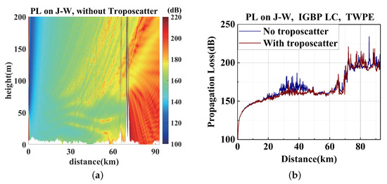
Figure 15.
The PL on Jiaxing–Wuxi (a) in space (b) at a height of 60 m. (a) PL on Jiaxing–Wuxi without the troposcatter. (b) PL on J–W at a height of 60 m with or without the troposcatter.

Figure 16.
The PL on Shanghai–Wuxi (a) in space (b) at a height of 60 m. (a) PL on Shanghai–Wuxi without the troposcatter. (b) PL on S–W at a height of 6 0m with or without the troposcatter.
Based on this, it can be concluded that the non-uniform turbulence model superimposed on the non-uniform tri-fold four-parameter hybrid duct has a boosting effect on the inter-city propagation at 40 km and further. This may lead to the fact that, on the urban link from surrounding cities to Wuxi, such as the Shanghai–Wuxi link, the downlink signal of the remote base station will likely interfere with the uplink signal at the first 20–60 km of the link, affecting the random uplink access user. After 60 km, or due to sudden changes in terrain, or being too far away, the PL of the two links at the antenna height of 60 m exceeds 160 dB, which means the sensitivity that can be distinguished by the receiver. Therefore, the possibility of remote interference is not considered, but simulated by the improved scattering PE model, the PL of this middle section of the path link is reduced, the signal of the transmitting section may propagate to the user area of this section, and remote interference may still occur. When considering the farthest distance that useful signals can propagate between intercity links, the PL calculated by adding the influencing factors of tropospheric turbulence in this section also shows that it is possible to deploy base stations as precise as possible based on ensuring accurate communications and no remote interference. For example, a base station relay can be set up at 20 km where similar terrain and LCs are distributed, such as Shanghai–Wuxi, and a base station relay can be assumed at 60 km where similar terrain and LCs are distributed, such as Jiaxing–Wuxi link. In addition, because the two intercity links are close together, if Wuxi receives a useful signal from the Jiaxing link under the influence of a stronger duct, it may also receive a remote signal from Jiaxing at the same time, causing user communication interference. It could be concluded that the influence of tropospheric turbulence has an important reference value for deploying base stations and avoiding remote interference between base stations.
4.2. Verification of TWPE
Propagation losses from Shanghai–Wuxi using the same environment settings and radar parameters as intercity links of Hangzhou–Wuxi are shown in Figure 17. Different LC types were considered to evaluate the PL distribution on the S–W link using the TWPE model, as shown in Figure 17a,b. The AREPS result with the IGBP LC type is shown in Figure 17c. The range-dependent PLs at a ducting layer of 60 m on the S–W link of different LCs using TWPE and AREPS are compared in Figure 17d.

Figure 17.
The propagation loss with tropospheric scattering, IGBP LC, and DEM considered on Shanghai–Wuxi. (a) PL from Shanghai–Wuxi using TPWE and IGBP LC. (b) PL from Shanghai–Wuxi using TPWE, WAT, and GRA LC. (c) PL from Shanghai–Wuxi using AREPS and IGBP LC. (d) PL at the duct-trapping layer of 60 m of different LCs.
The propagation distance from Shanghai to Wuxi is about 115 km. Moreover, the terrain relief of the intercity link between Shanghai to Wuxi was kept below 10 m, which fits the application condition of the paraxial approximation of PWE. Based on the plain cover characteristics of East China, the land types of terrain on this intercity link are classified into grassland and water bodies at first. We conducted WAPE considering terrain relief, tropospheric turbulence, and dielectric permittivity on the first assumption and the land types of IGBP from MODIS data.
From Figure 17a,b, we used the IGBP cover type form MODIS with a resolution of 250 m, the PL distribution basically remains at the same level as the conducted form TWPE with LC type using grassland and water bodies. Figure 17d shows the PL distribution at the transmitting height of 60 m in the trapping layer of the surface-based duct. The PL at a height of 60 m using the LC type of IGBP from MODIS between 60 and 105 km is larger than that of using the grassland and water bodies as terrain features. On the remaining links, the PL using the two LC classifications are reversed or on the same level. AREPS uses the RPO model to divide the long-distance ducting propagation into four models to improve the calculation speed and facilitate engineering applications. There was not much to consider on the tropospheric scatter and terrain scatter in AREPS. Therefore, the PL trend was similar but AREPS result was 20 dB lower than TWPE result.
Given that the industry can achieve GPS receivers with tracking sensitivity below −160 dBm, at the height of the surface-based duct within the receiver, the realistic LC classification could be an essential environmental condition to evaluate whether CCI would happen on this intercity link. The possibility of CCI could be an essential decision support of 5G base station deployment.
Propagation loss from Jiaxing to Wuxi using the same environment settings and radar parameters, the same as in the previous section, are shown in Figure 18. Different LC types were considered to evaluate the PL distribution on the J–W link using TWPE model, as shown in Figure 18a,b. The AREPS result with the IGBP LC type is shown in Figure 18c. The range-dependent PLs at a ducting layer of 60 m on the J–W link of different LCs using TWPE and AREPS are compared in Figure 18d.
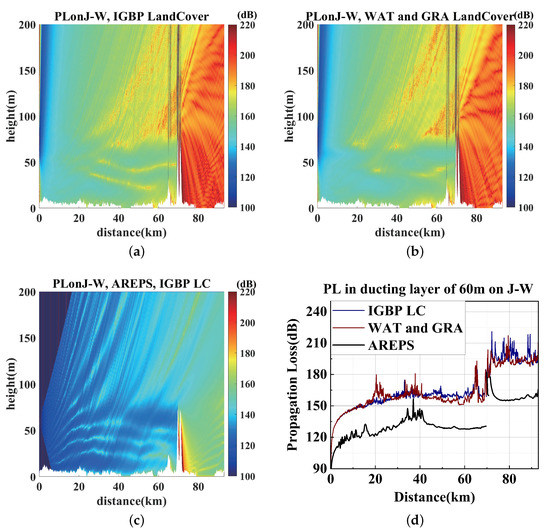
Figure 18.
The Propagation loss with tropospheric scattering, IGBP LC, and DEM on Jiaxing–Wuxi. (a) PL from Jiaxing–Wuxi using TPWE and IGBP LC. (b) PL from Jiaxing–Wuxi using TPWE, WAT, and GRA LC. (c) PL from Jiaxing–Wuxi using AREPS and IGBP LC. (d) PL at the duct-trapping layer of 60 m of different LCs.
The distance of the intercity link from Jiaxing to Wuxi was about 93 km. Moreover, the terrain relief was around 20 m, besides a peak, which had a maximum height of 80 m. The peak was not high enough to cut off ducting and diffraction, and the radio wave elevation angle fit the maximum limit of TWPE.
From Figure 18b, we can see that when we considered the LC types more specifically, the PL on the intercity link Jiaxing–Wuxi increased slightly. Due to the limitation of the RPO model in AREPS using a range-independent RO model in the range-dependent environment, in extreme cases this can cause discontinuities along the RO/PE boundary [28]. This discontinuity occurred in the peak of the intercity link of Jiaxing–Wuxi.
The two classifications of LC types do not give obvious differences probably due to the classifications of grasslands and waterbodies being close to those of the real LC type distributions on the intercity link. It can be seen from Figure 9d that the real LC data on the Jiaxing–Wuxi link extracted by the IGBP LC classification also consisted of most WAT—17 in IGBP LC1—and several other kinds of vegetation categories. Moreover, the classifications from MODIS data just gave more specific resolutions on the LC types. Additionally, when we used the LC type classification in the resolution of 250 m from MODIS, the fast fading was much more obvious.
4.3. Effects of Different Land Covers
The previous section shows (assuming that the LC is grassland and water bodies) the PL trend and numerical range of PL at the antenna height layer when mixed ducts and tropospheric turbulence occur on the plain area. The accuracy of the results of the TWPE model with tropospheric turbulence was verified. The PL situation covered by different LCs will be discussed in this section.
In this section, three types of LCs, barren or sparsely vegetated (BSV), urban and built-up (URB), and savannas (SAV), were selected, respectively. The over-the-horizon propagation was studied on the Shanghai–Wuxi and Jiaxing–Wuxi links considering the joint effect of tropospheric turbulence and the duct. Figure 19 shows the PL distribution on Shanghai–Wuxi link. The parameters are the same as in the previous section, except that the LC dielectric parameters use the values corresponding to Table 3, respectively.

Figure 19.
The PL using the improved TWPE with (a) BSV, (b) URB, (c) SAV LC, on Shanghai–Wuxi. (a) PL on S–W with BSV LC. (b) PL on S–W with URB LC. (c) PL on S–W with SAV LC.
We used MSE to compare the PLs on Shanghai–Wuxi under three hypothetical LC types with the PLs on the S–W link under real IGBP LCs; see Figure 17a. The results are shown in Figure 20.
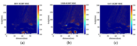
Figure 20.
The MSE of PL using the improved TWPE between IGBP LC and different LCs, on Shanghai–Wuxi. (a) BSV-IGBP MSE of PL on S–W. (b) URB-IGBP MSE of PL on S–W. (c) SAV-IGBP MSE of PL on S–W.
To clearly compare the influences of the PLs of the transmission signal in the ducting layer of the Shanghai–Wuxi link under the backgrounds of several different LC types, we compared the PLs of the link at a height of 60 m in the ducting layer, as shown in Figure 21.
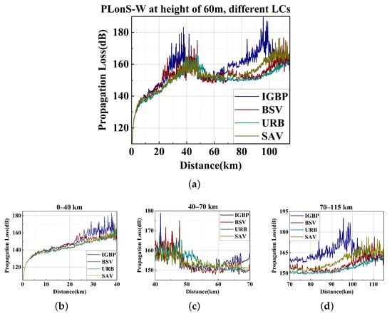
Figure 21.
The propagation loss using the improved TWPE at a height of 60 m using different land covers, on Shanghai–Wuxi. (a) PL on S–W at different LCs at a antenna height of 60 m. (b) PL on S–W at a range of 20–40 km at different LCs. (c) PL on S–W at a range of 40–70 km at different LCs. (d) PL on S–W at a range of 70–115 km at different LCs.
According to the impedance boundary conditions applicable to irregular terrain, it is assumed that the LCs are BSV/URB/SAV. Figure 19 shows the spatial distribution of the PL on Shanghai–Wuxi link when the three types of hypothetical single LCs are distributed. Figure 20 shows the spatial distribution of the mean square error (MSE) obtained by assuming different LC types and the real LC classified by IGBP on the Shanghai–Wuxi link. It can be seen that different LCs have a great influence on the PL accuracy, particularly at the antenna propagation height near the surface within the duct trapping layer. From the PL distribution of the antenna height layer shown in Figure 21, it can be seen that on the Shanghai–Wuxi link, the difference between the PL coverage of different LCs is mainly reflected in the front section and the rear section. The 20–40 km and 70–100 km sections both show that the IGBP LC results are significantly larger than the PL covered by a single LC type. The research in [29] shows that terrain fluctuation has a great influence on the PL distribution of the signal’s over-the-horizon propagation. The results in this section show that the changes of different LCs may increase the PL, especially in the section with sudden and large terrain fluctuations, the actual situation may be a sudden change of LC, so it is more necessary to consider the coverage of real terrain.
Figure 22 shows the over-the-horizon PL distribution of different LCs on the Shanghai–Wuxi link when the receiving antenna height is 40 m. Different from the results obtained with the receiving antenna height of 60 m in Figure 21, there is a significant difference on the range-dependent PL in various LCs at 40 km; that is, in the middle of the link. However, under the backgrounds of the distribution of real LCs, the calculated PL still exceeds the sensitivity threshold of the receiving antenna at a height of 40 m at range of 45 km, blocking the long-distance propagation of the signal. Therefore, the possibility of users receiving remote interference on the road section beyond the 45 km Shanghai–Wuxi link is small. If the road section undergoes urban renovation (biased towards the dark cyan line in URB, Figure 22), or vegetation green development (biased towards the dark yellow line in SAV, Figure 22), the propagation distances of the communication signal could vary according to the specific meteorological conditions and changes in the distribution of LC features. Therefore, according to the changes of the annual live updates of the LC types, the more finely the classification of LCs that may develop in the future, and the dielectric parameter values corresponding to the more accurate LC types, the reception range of communication signals could be estimated through a more accurate model.
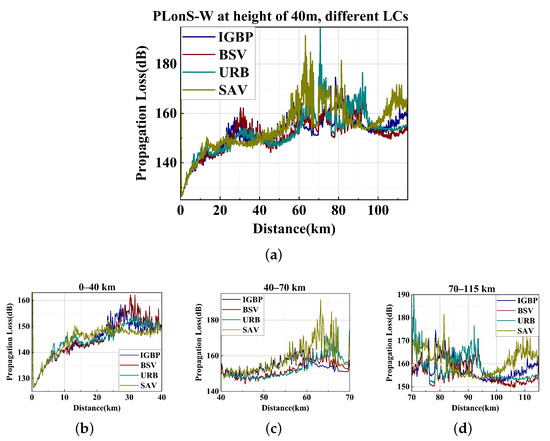
Figure 22.
The propagation loss using the improved TWPE at a height of 40 m using different land covers, on Shanghai–Wuxi. (a) PL on S–W at different LCs at an antenna height of 40 m. (b) PL on S–W at a range of 20–40 km at different LCs. (c) PL on S–W at a range of 40–70 km at different LCs. (d) PL on S–W at a range of 70–115 km at different LCs.
Figure 23 shows the PLs of over-the-horizon propagation on Jiaxing–Wuxi with three hypothetical LCs considering the joint effect of the tropospheric turbulence and duct. The parameters are the same as in the previous section.

Figure 23.
The MSE of PL using the improved TWPE between IGBP LC and different LCs on Shanghai–Wuxi. (a) PL on J–W with BSV LC. (b) PL on J–W with URB LC. (c) PL on J–W with SAV LC.
We used MSE to compare the PLs under three hypothetical LC types with the PLs under real IGBP LCs on the Jiaxing–Wuxi link, as shown in Figure 18a. The results are shown in Figure 24.

Figure 24.
The MSE of PL using the improved TWPE between IGBP LC and different LCs on Shanghai–Wuxi. (a–c) BSV-IGBP MSE of PL on J–W.
On the path link of Jiaxing–Wuxi, the propagation distance was 93 km, but there was a high terrain fluctuation at 70 km. Figure 24 shows the MSE between the parameter conditions of the assumed single LC feature distribution and the real IGBP feature distribution. As can be seen from Figure 24, the MSE between the PL calculated on the assumed single LC type parameters and the PL calculated on the real LC parameters classified by IGBP started to grow from the top of the duct, which was also the energy leaking area at a distance of 70 km from Jiaxing. It was obvious that the MSE of PL at the antenna height was the smallest when the assumed LC was SAV, which was closely related to the distribution of LCs on the intercity link. According to IGBP terrain classification in Figure 9d, Jiaxing–Wuxi was mostly covered by water bodies, and also contained many types of landform switching.
In order to clearly compare the influence of the PLs of the transmission signal in the ducting layer on Jiaxing–Wuxi link under the backgrounds of several different LC types, we compared the PLs of the link at a height of 60 m in the ducting layer, as shown in Figure 25.

Figure 25.
The Propagation loss using the improved TWPE at a height of 60 m using different land covers, on Jiaxing–Wuxi. (a) PL on J–W at different LCs at at antenna height of 60 m. (b) PL on J–W at range of 0–40 km at different LCs. (c) PL on J–W at a range of 40–70 km at different LCs. (d) PL on J–W at a range of 70–93 km at different LCs.
Figure 25 shows the range-dependent PL at the antenna height of 60 m on different LC types. As shown in Figure 21c, the PL increased sharply, which was around 200 dB. Therefore, the difference of the PL calculated using TWPE between a single LC and on IGBP LC was not obvious at 0–20 km. From the 20–40 km PL on the J–W of different LCs shown in Figure 25a, the over-the-horizon PL on IGBP LC was close to that on BSV LC, but higher than the results of the URB or SAV LC. The PL of IGBP LC was slightly smaller in the 0–20 km section of Jiaxing–Wuxi. The PL distribution of different LCs at 0–40 km on the antenna height layer was similar to that of the Shanghai–Wuxi link, which is helpful for the deployment of short-distance 5G base stations. The middle section at a range of 40–70 km was mainly affected by terrain fluctuations and ducts, and the PL was kept within a certain range. The LC of this section can be roughly assumed using the simplified dielectric permittivity to simulate the PL distribution and could be performed to save time and costs. From the PL distribution of 70–93 km, it can be inferred that when the terrain fluctuation exceeds 80 m, the PL might exceed the minimum resolution value of the GPS receiver, so that the possibility of remote interference on the link can be ignored. Moreover, when long-distance communication is required, the corresponding 5G relay base station deployment can be reasonably arranged with reference to this result.
Figure 26 shows the range-dependent PL distribution at the height of the receiving antenna when the receiving antenna is 40 m on the Jiaxing–Wuxi link. At 40–70 km in the middle section of the link, the PLs simulated by different types of LC begin to show obvious differences. Compared with Figure 25 when the receiving antenna height is 60 m, the overall PL is reduced; that is, when the receiving antenna height is lower, the propagation distance of the signal increases. Within the range of signal-noise-ratio (SNO) that the antenna can distinguish, when the receiving antenna is 40 m, the signal can be transmitted to about 45 km. In addition, if the LC on the link develops in a unified manner, such as highway development, greening, desertification, etc.; that is, if the LC on the link does not change much, as shown in Figure 23b, the overall PL is reduced, and the propagation distance may increase by 10–20 km.

Figure 26.
The propagation loss using the improved TWPE at a height of 40 m using different land covers, on Jiaxing–Wuxi. (a) PL on J–W at different LCs at an antenna height of 40 m. (b) PL on J–W at a range of 0–40 km at different LCs. (c) PL on J–W at a range of 40–70 km at different LCs. (d) PL on J–W at a range of 70–93 km at different LCs.
4.4. Analysis of Remote Interference between Different Intercity Links
Comparing Figure 22, Figure 23, Figure 24 and Figure 25, the Shanghai–Wuxi link is relatively close to the Jiaxing–Wuxi link, and base stations on one of the links from 0 to 45 km might receive an uplink signal from another city, resulting in remote signal interference. Therefore, this section compares the PL of the four links with the receiving antenna heights of 60 m and 40 m, respectively (the heights are both within the trapping layer of the surface-based duct assumed in this paper), as shown in Figure 27. The probability of possible remote interference of inter-city signals was analyzed.
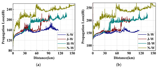
Figure 27.
The range-dependent PL on four intercity links at antenna heights of (a) 60 m and (b) 40 m. (a) Range-dependent PL from four cities to Wuxi at ANH = 60 m. (b) Range-dependent PL from four cities to Wuxi at ANH = 40 m.
As shown in Figure 27, due to large terrain fluctuations, the propagation distance on Hangzhou–Wuxi and Nanjing–Wuxi links were about 15 and 40 km, respectively. From the city orientation shown in Figure 8, it can be seen that Hangzhou, Jiaxing, and Shanghai are all located within a radius of about 100 km southeast of Wuxi, and signal serialization may occur between the links from each city to Wuxi. As shown in Figure 9d, the Jiaxing–Wuxi link had a sudden increase in PL at different receiving antenna heights due to relatively large terrain fluctuations and switching of LCs. In the 0–40 km stage, the signals transmitted from Hangzhou, Jiaxing, and Shanghai were relatively stable under the effect of surface-based duct and tropospheric turbulence. Therefore, within a certain radius close to Wuxi, remote interference may occur among the signals of the three urban links, where a useful signal from one city may become an interfering signal received by another user. Based on the analysis of this phenomenon, it can be considered that when the base stations are deployed among relatively close cities, combined with a variety of possible ducting conditions, the tropospheric turbulence effect, and the annual update of the distribution of LCs, the simulation prediction of the propagation of over-the-horizon signals between cities can be carried out. According to the results, within the relevant radius, methods such as high obstacle blocking, alternating high and low antennas, and flexible site selections of base stations could be adopted to carry out preventive 5G base station deployment between cities with similar terrains to what we simulated in this paper, where remote interference may occur.
4.5. Deep Learning Model Predicts Land-Based Ducting Propagation Using Geomorphology Data
It was found that the intercity links whose terrains are similar to that of the intercity link analyzed in the previous sections, such as Shanghai–Wuxi or Jiaxing–Wuxi, are prone to the ducting effects caused by meteorological changes, causing remote interference at the antenna height. Since most of the relevant cities and landform data are less available, in this section, we use d1300 randomly generated datasets with different propagation distances, terrains, and land covers to perform physical simulations of over-the-horizon PL distributions under the same radar parameters, duct parameters, and random turbulence as the previous sections. The intercity link maximum distance was randomly generated within 90–100 km. The terrain relief height was randomly generated within 0–20 m. The LC type was randomly generated between 9 and 17 according to the IGBP classification scheme, and the corresponding dielectric parameters are listed in Table 3.
The simulated 1300 groups of terrain, land cover, and dielectric parameters at different distances and the PL at the corresponding antenna height were used for deep learning modeling. We intended to build a deep learning model to predict the PL on the intercity link with input parameters of terrain and land cover characteristics, and the ducting and radar environment settings remained the same as in previous sections.
Before training, because the randomly generated data may have been inconsistent with the actual situation, the obvious errors of the forward-propagation results were eliminated. A total of 56 sets of data were eliminated, and the remaining 1244 sets of data were used for deep learning modeling. After shuffling the order of datasets, the first 900 datasets were used as training sets, and the last 344 sets of data were used to test the training model. The deep multilayer perceptron (DMLP) network was used here for deep learning modeling. We continuously optimized the parameters to obtain the optimal model, and a total of 4000, 2000, 3000, and 999 neural networks were built for training. The schematic diagram of the deep learning forward prediction model is shown in Figure 28.

Figure 28.
The schematic diagram of the deep learning forward-prediction model.
One of the results calculated by the TWPE scattering model in the test set was used to compare the prediction result by the deep learning model, as shown in Figure 29a, with the antenna height at 60 m, and Figure 30a with the antenna height at 40 m. Using the mean square error as the loss function, the formula of the specific loss function is as follows:
where represents the range-dependent PL predicted by the network, is the true range-dependent PL calculated by the TWPE model, and n is the number of groups of training datasets.
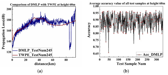
Figure 29.
DMLP prediction at a height of 60 m and accuracy distribution. (a) PL Prediction using DMLP at an antenna height of 60 m. (b) DMLP of PL at a height of 60 m of accuracy on the test samples.

Figure 30.
DMLP prediction at a height of 40 m and accuracy distribution. (a) PL prediction using DMLP at an antenna height of 40 m. (b) DMLP of PL at a height of 40 m accuracy on test samples.
Using the following definition to give the model prediction accuracy functions to evaluate the quality of the established model
The accuracy of each range step was solved at antenna heights of 60 or 40 m, and the mean value was defined as the predicted accuracy of the sample. Then the predicted accuracy distribution was obtained on each tested sample. The accuracy results of test datasets are shown in Figure 29b and Figure 30b, respectively.
When the antenna height was 60 m, the MSE of the DMLP prediction was 118.202749. When the antenna height was 40 m, the MSE was 108.696593. After the optimized deep learning parameters were well trained, they could quickly and efficiently predict (at a certain fixed antenna height, terrain, and landform) whether there would be communication interference problems between cities around 100 km apart with ducting and turbulence.
It can be seen from Figure 29b and Figure 30b that the prediction accuracy function of the test set of the DMLP model simulation results is mostly kept between 0.8 and 1.0, and a good prediction effect was achieved. We selected two groups of DMLP predictions with relatively good test results and compared them with the TWPE simulation results. Figure 29a and Figure 30a show that the DMLP prediction make large errors after 80 km, and the DMLP prediction results fluctuate greatly.
To improve the prediction effect of the model, we introduced the long- and short-term memory (LSTM) network model to perform deep learning modeling on the original 1244 sets of data, and used two layers of LSTM networks with 80 and 60 neural units, respectively. The LSTM has requirements for the network input dimension. It is a matrix form of [number of samples, number of expansions in time steps, number of sample features at each time step]. To meet the requirement of this parameter dimension, a total of 1244 groups of training and testing data of the original fully-connected layer were rearranged according to the four input features, which was distance, terrain fluctuation, the real part, and imaginary part of the dielectric parameters of the corresponding land covers. Then the input parameter dimensions were converted into the three-dimensional matrix. After the deep training using LSTM network, the prediction range-dependent PLs at antenna heights of 60 and 40 m were obtained, as shown in Figure 31 and Figure 32.

Figure 31.
LSTM prediction at a height of 60 m and accuracy distribution. (a) PL prediction using LSTM at an antenna height of 60 m. (b) LSTM of PL at a height of 60 m accuracy on test samples.
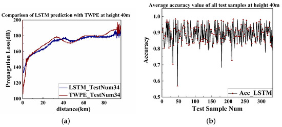
Figure 32.
LSTM prediction at a height of 40 m and accuracy distribution. (a) PL prediction using LSTM at an antenna height of 40 m. (b) LSTM of PL at a height of 40 m accuracy on test samples.
The LSTM model still maintains a good prediction effect. The MSE of LSTM prediction of PLs at an antenna height of 60 m was 93.749120. Moreover, the MSE of LSTM prediction of PLs at an antenna height of 40 m was 90.245694. According to the loss value, the MSE of LSTM was smaller than that of DMLP. The prediction accuracy of LSTM remained mostly between 0.8 and 1.0. However, the shortcoming of the rapid fluctuation and the large error after 80 km of DMLP were greatly improved in LSTM.
The terrain and land cover datasets used in the deep learning model were randomly generated. There might have been some random terrain and LCs that did not conform to the actual continuous distribution, so the model training results have certain errors. However, it can be seen that the topography and LC types have great influence on the PL distribution over the horizon. Therefore, it is effective and efficient to use the deep learning model to predict the over-the-horizon PL of the intercity link in the ducting environment with different landforms. The results also show that topography and LC types have great influence on the over-the-horizon propagation when a terrestrial duct happens. Subsequent continuous improvements of parameters to optimize the deep learning model may improve the prediction accuracy.
5. Discussion
On plain areas, tropospheric ducting and turbulence could effect the signals to make an over-the-horizon propagation of 5G communication signals. Due to the dense distribution of 5G base stations, chances of CCI increases between intercity links when ducts form because of unusual changes, such as temperature increases with height occurring in meteorological conditions. Moreover, the tropospheric turbulence related to the distribution of the hybrid duct height had a sub-segment effect on the over-the-horizon propagation. Before 40 km, the tropospheric ducting took the lead in the over-the-horizon transmission; in the middle of the 40–80 km, the tropospheric turbulence boosted the propagation effect by making the propagation signals multi-reflect on the air masses at the top layer of duct. If the PL in this middle section was reduced to the antenna receiving sensitivity range, the transmitted signal might have been received by local users when it reached the middle and rear sections of the urban link, resulting in remote interference.
If there is no major topographic change, the tropospheric turbulence will still play a role in the rear section of the intercity link, which can reduce the PL. However, because the propagation distance is too long, the signal may exceed the antenna receiving sensitivity at a distance of 70 km and will not be received by users in this section. If there are large topographic changes between cities, topographic fluctuations play a dominant role in over-the-horizon propagation. Figure 13b shows that peaks over 200 m make the PL exceed 160 dB immediately. Obstacles beyond the transmit antenna height could cut off the propagation entirely. When no obvious peaks or valleys exist on intercity links, there is the probability of duct occurrences after rain or at night on waterside plain or coastal cities areas. In our simulations on Shanghai–Wuxi and Jiaxing–Wuxi, signals propagating beyond the horizon with propagation loss did not decrease much in the duct-trapping layer when surface-based duct and tropospheric scattering occurred. Therefore, with the dense deployment of 5G communication base stations, tropospheric ducting and scattering effects may jointly cause CCI on intercity links with undulating terrain in plain areas. Therefore, it is essential to accurately model the over-the-horizon propagation of intercity link signals caused by the combined effects of duct and tropospheric turbulence effects, considering real terrain and LCs. The simulation results could be used in preventive deployment of 5G base stations and targeted deployment of relay base station locations, which could greatly save related costs.
A total of 1300 sets of randomly generated data were used to conduct deep learning training based on the TWPE simulated results. The training parameters with better effects after multiple optimizations were selected. The model was built with fixed radar antenna parameters and atmospheric environment parameters. The topography and landform data were entered to predict the PL distribution at the antenna height layer, and achieved good prediction results. When an intercity link whose terrain and land form are similar to the plain area is obtained, the deep learning model can be used to effectively and quickly predict the PL distribution, so as to evaluate the possibility of remote interference and carry out subsequent base station distribution deployment.
6. Conclusions
Due to the air mass flow, the inhomogeneous tropospheric turbulence exists almost all of the time. The tropospheric duct is very likely to be formed after heavy rain in the summer or with day–night temperature change. Researchers have confirmed the truth of over-the-horizon propagation of radio waves over the sea. On the land, when we simulate the over-the-horizon propagation to evaluate whether CCI could form between cities, the terrain relief, land cover type, and dielectric constant of land cover would be essential. The real elevation of intercity links from DEM data, real land cover type from MODIS data, and the corresponding dielectric permittivity of land cover types from different literature were considered in our simulation. Moreover, the method of the terrain shift map on WPE with range-dependent non-uniform turbulence was used to simulate the propagation loss on real intercity links. We also used the deep learning model to predict the distribution of the PL of the over-the-horizon signal cities at different distributions of intercity land forms in the ducting and random tropospheric turbulence environments. The prediction loss value was stable at about 0.6 m. This deep learning model could be applied to inter-city remote interference prediction when ducting occurs in similar plain terrains.
When terrain relief is rather high compared to the duct trapping layer height, the effects of terrain dominate in the propagation. When the terrain relief is relatively flat with no large peaks, ducting and turbulence dominate in the propagation. In our simulation, propagation loss could keep under 160 dB in the trapping layer of duct on intercity link length around 100 km, which could form CCI between cities. Thus, with 5G base stations, frequency band networking, arrangements of large-scale antenna arrays, the effects of tall building block outs, and tropospheric ducts need to be considered.
While the deployment of 5G base stations is still in full swing, the 6G satellite low-orbit internet has also developed simultaneously. Due to the limited number of satellites that can be accommodated in low-Earth orbit, the world is currently undergoing constellation plans in different states, such as networking, testing, and project approval, and is conducting an unprecedented competition that cannot be lost. The development of satellite communication will have higher requirements on the utilization rate of the current communication frequency band, signal propagation efficiency, and anti-interference ability. This requires us to take into account various dynamic conditions, such as meteorology, terrain, and LC types, and accurately model the propagation of useful and interfering signals for communication at current frequency band.
With the continuous development of commercial areas and urban–rural junctions, the topography and land cover types of build-up areas will continue to change. The coastal and plain cities near the water are more prone to form ducts, and the coastal cities are developing rapidly. Urban buildings, greening, natural landscape development, urban–rural integration areas development, crop planting, etc., are all constantly developing and changing. The LC type has a very obvious influence on the propagation loss of the over-the-horizon communication, so the over-the-horizon effect caused by the duct and tropospheric turbulence may trigger remote CCI to coastal cities. The uplink transmission signal may be exceeded by the guard time slot, interfering with the downlink received signal. The work done in this paper could play a guiding role in the deployment of 5G base stations to prevent possible CCI and the selection of base station relay locations.
The analysis of this paper gives a prediction method of communication signals in real mixed duct and non-uniform tropospheric turbulent environments for real and constantly evolving and changing land covers. The dielectric permittivity of constantly changing land coverage could be improved by referencing more literature studies and experimental results.
Author Contributions
Conceptualization, K.Y., Z.W. and J.W.; Data curation, X.G. and K.Z.; Formal analysis, T.W.; Investigation, K.Y.; Project administration, X.G.; Resources, J.W.; Supervision, T.Q.; Validation, K.Z.; Writing—original draft, K.Y.; Writing—review and editing, Z.W., T.W. and L.L. All authors have read and agreed to the published version of the manuscript.
Funding
Project supported by the National Natural Science Foundation of China (grant nos. 62271381, 62005205, 62071359, 61975158, 61901335, and 62001377) and Shaanxi Province Science Foundation for Youth, China (grant no. 2020JQ-329).
Data Availability Statement
The DEM data set is provided by Geospatial Data Cloud site, Computer Network Information Center, Chinese Academy of Sciences. (http://www.gscloud.cn). The MODIS data products are archived and available via FTP from the Land Processes Distributed Active Archive Center(DAAC) at EROS Data Center. (https://ladsweb.modaps.eosdis.nasa.gov/).
Conflicts of Interest
The authors declare no conflict of interest.
Abbreviations
The following abbreviations are used in this manuscript:
| 5G | The fifth generation |
| PE | parabolic equation |
| DEM | digital elevation model |
| MODIS | moderate-resolution imaging spectroradiometer |
| IGBP | International Geosphere-Biosphere Program |
| WAPE | wide-angle parabolic equation |
| TWPE | terrain wide-angle parabolic equation |
| AREPS | advanced refractive effects prediction system |
| CCI | co-channel interference |
| PL | propagation loss |
| LC | land cover |
| MAP | maximum a prior |
| ML | maximum likelihood |
| DMLP | deep multilayer perceptron |
| LSTM | long and short-term memory |
References
- Huang, X.; Dong, J.; Wang, W.; Xu, H. A case study of 5G network planning based on Massive MIMO. Telecom Eng. Tech. Stand. Abbr. 2017, 30, 50–54. [Google Scholar]
- Turton, J.D.; Bennetts, D.A.; Farmer, S.F.G. An introduction to radio ducting. Meteorol. Mag. 1988, 117, 245–254. [Google Scholar]
- Leontovich, M.; Fock, V.A. Solution of the problem of propagation of electromagnetic waves along the earth’s surface by the method of parabolic equation. J. Phys. USSR 1946, 10, 13–23. [Google Scholar]
- Hardin, R.H.; Tappert, F.D. Applications of the Split-Step Fourier Method to the Numerical Solution of Nonlinear and Variable Coefficient Wave Equations. Siam Rev. 1973, 15, 423. [Google Scholar]
- Feit, M.D.; Fleck, J.A. Light propagation in graded-index optical fibers. Appl. Opt. 1978, 17, 3990–3998. [Google Scholar] [CrossRef]
- Thomson, D.J.; Chapman, N. A wide-angle split-step algorithm for the parabolic equation. J. Acoust. Soc. Am. 1983, 74, 1848–1854. [Google Scholar] [CrossRef]
- Kuttler, J.R. Differences between the narrow-angle and wide-angle propagators in the split-step Fourier solution of the parabolic wave equation. IEEE Trans. Antennas Propag. 1999, 47, 1131–1140. [Google Scholar] [CrossRef]
- Levy, M. Parabolic Equation Methods for Electromagnetic Wave Propagation, 1st ed.; The Institution of Engineering and Technology: London, UK, 2000; pp. 268–272. [Google Scholar]
- Janaswamy, R. Path loss predictions in the presence of buildings on flat terrain: A 3-D vector parabolic equation approach. IEEE Trans. Antennas Propag. 2003, 51, 1716–1728. [Google Scholar] [CrossRef]
- Hu, H.; Chen, Z.; Chai, S.; Mao, J. Research on mobile communication radio propagation characteristic based on 3DPE. In Proceedings of the 2005 Asia-Pacific Microwave Conference, Suzhou, China, 4–7 December 2005. [Google Scholar]
- Rasool, H.F.; Pan, X.M.; Sheng, X.Q. A fourier split-step based wide-angle three-dimensional vector parabolic wave equation algorithm predicting the field strength over flat and irregular forest environments. Appl. Comput. Electromagn. Soc. J. 2019, 34, 874–881. [Google Scholar]
- Dockery, G.D.; Konstanzer, G.C. Recent advances in prediction of tropospheric propagation using the parabolic equation. Johns Hopkins APL Tech. Dig. 1987, 8, 404–412. [Google Scholar]
- Dockery, D.; Kuttler, J.R. An improved impedance-boundary algorithm for Fourier split-step solutions of the parabolic wave equation. IEEE Trans. Antennas Propag. 1996, 44, 1592–1599. [Google Scholar] [CrossRef]
- Kuttler, J.R.; Dockery, G.D. Theoretical description of the parabolic approximation/Fourier split-step method of representing electromagnetic propagation in the troposphere. Radio Sci. 1991, 26, 381–393. [Google Scholar] [CrossRef]
- Donohue, D.J.; Kuttler, J.R. Propagation modeling over terrain using the parabolic wave equation. IEEE Trans. Antennas Propag. 2000, 48, 260–277. [Google Scholar] [CrossRef]
- Hitney, H.V. A practical tropospheric scatter model using the parabolic equation. IEEE Trans. Antennas Propag. 1993, 41, 905–909. [Google Scholar] [CrossRef]
- Ivanov, V.; Shalyapin, V.; Levadny, Y.V. Microwave scattering by tropospheric fluctuations in an evaporation duct. Radiophys. Quantum Electron. 2009, 52, 277–286. [Google Scholar] [CrossRef]
- Wang, H.G.; Zhang, L.J.; Guo, X.M.; Wu, Z.S. Study of Fading Characteristics of Evaporation Duct Channel for Microwave Over-the-Horizon Propagtaion. J. Microw. 2013, 29, 1–5. [Google Scholar]
- Song, S.T. Analysis on Influence of Tropospheric Atmosphere State on the Transmission Loss of Troposcatter Communication Link. Radio Commun. Technol. 2015, 41, 46–48. [Google Scholar]
- Wanger, M.; Gerstoft, P.; Rogers, T. Estimating Refractivity from Propagation Loss in Turbulent Media. Radio Sci. 2016, 51, 1876–1894. [Google Scholar]
- Liu, X.; Wu, Z.; Wang, H. Inversion method of regional range-dependent surface ducts with a base layer by Doppler weather radar echoes based on WRF model. Atmosphere 2020, 11, 754. [Google Scholar] [CrossRef]
- Liu, X.; Wu, Z.; Wang, H. Inversion for Inhomogeneous Surface Duct without a Base Layer Based on Ocean-Scattered Low-Elevation BDS Signals. Remote Sens. 2021, 13, 3914. [Google Scholar] [CrossRef]
- Reuter, H.I.; Nelson, A.; Jarvis, A. An evaluation of void-filling interpolation methods for SRTM data. Int. J. Geogr. Inf. Sci. 2007, 21, 983–1008. [Google Scholar] [CrossRef]
- Dobson, M.C.; Ulaby, F.T.; Hallikainen, M.T.; El-rayes, M.A. Microwave Dielectric Behavior of Wet Soil-Part II: Dielectric Mixing Models. IEEE Trans. Geosci. Remote Sens. 1985, GE-23, 35–46. [Google Scholar]
- Tang, Y.H.; Huang, Y. Spatial Distribution Characteristics of the Percentage of Soil Fertility Contribution and Its Associated Basic Crop Yield in Mainland China. J. Agro-Environ. Sci. 2009, 28, 1070–1078. [Google Scholar]
- Xiao, J.K. Microwave Dielectric Property of Solid Bitumen. Geochimica 1983, 1, 24–31. [Google Scholar]
- Zhang, J.R. The dielectric constant in microwave remote sensing. Remote Sens. Technol. Appl. 1994, 9, 30–43. [Google Scholar]
- Hitney, H.V. Hybrid ray optics and parabolic equation methods for radar propagation modeling. In Proceedings of the 92 International Conference on Radar, International Conference, Brighton, UK, 12–13 October 1992; pp. 58–61. [Google Scholar]
- Yang, K.; Wu, Z.; Guo, X.; Wu, J.; Cao, Y.; Qu, T.; Xue, J. Estimation of co-channel interference between cities caused by ducting and turbulence. Chin. Phys. B 2021, 31, 024102. [Google Scholar] [CrossRef]
Publisher’s Note: MDPI stays neutral with regard to jurisdictional claims in published maps and institutional affiliations. |
© 2022 by the authors. Licensee MDPI, Basel, Switzerland. This article is an open access article distributed under the terms and conditions of the Creative Commons Attribution (CC BY) license (https://creativecommons.org/licenses/by/4.0/).