
Unmanned Aircraft System Applications in Damage Detection and Service Life Prediction for Bridges: A Review


Abstract
: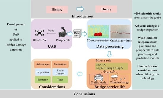
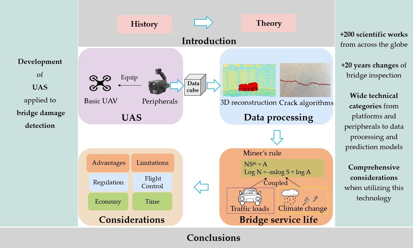
1. Introduction
2. Platforms and Peripherals
2.1. Platforms
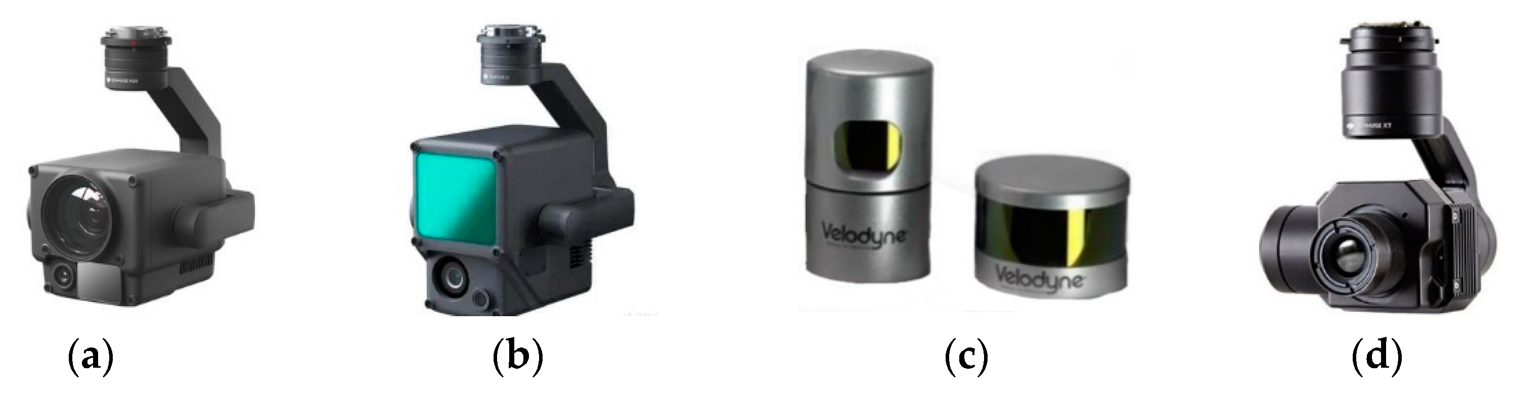
2.2. Peripherals
2.2.1. Visual Cameras
2.2.2. LiDAR Sensor
2.2.3. Thermal Infrared Imagery
2.2.4. Multispectral and Hyperspectral Sensors
2.2.5. Multi Sensors
2.2.6. Other Sensors

| Peripherals | Ref. | Focus | Work Mode | Main Advantages | Main Shortcomings |
|---|---|---|---|---|---|
| Visual cameras | [65,76,77,78,79,80,81,82] | Visible bridge damage | Image capture | Easy access to data | Appropriate shooting angle and advanced path planning |
| LiDAR | [43,84,85] | Bridge damage structure | Transmitting and receiving laser light | Scanning efficiency, overall point cloud data | Expensive, large data, seriously affected by vibration |
| Thermal infrared imagery | [86,87,88,89,90,91,92,93,94,95,96,97,98,99,100] | Internal defects | Active and passive thermal imaging | Internal defect identification | Hard to map processing and threshold extraction |
| Multispectral and hyperspectral | [102,103,105] | Spectral information | Push-broom scanning | Wider range of wavelengths | Complex dimension and noise reduction |
| Multi-sensors | [15,46,108] | Various data types | Multi-sensors cooperate | Various types of sensors | Hard to achieve data fusion |
3. Data Processing
3.1. Three-Dimensional Reconstruction
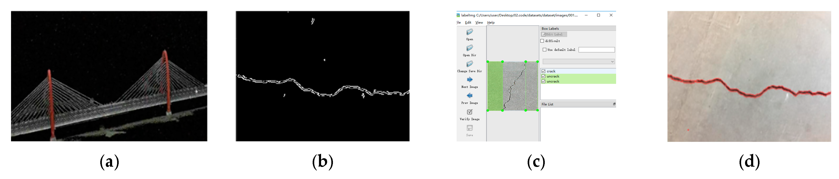
3.2. Image-Processing Techniques
3.3. Deep Learning in Neural Networks
4. Service Life Prediction Model
4.1. Traffic Load-Fatigue Damage Model
4.2. Anodic Dissolution and Hydrogen Embrittlement Corrosion Fatigue Coupled Model
4.3. Climate Change and Bridge Life Prediction Model
5. Considerations
5.1. Regulation
5.2. Economy and Time
5.3. Flight Control
6. Discussion
6.1. Advantages and Limitations
6.2. Future Needs
6.2.1. Self-Navigated Control and Path Planning
6.2.2. Automatic Damage Detection
6.2.3. Deterioration Model
7. Conclusions
- (i).
- robust autonomy: how to produce verifiable and scrutiny-proof algorithms that lead to desired emerging outcomes with real-time damage detection.
- (ii).
- UAS flight strategy: facilitating high-efficiency damage information extracts and flight path manipulations, depending on UAS technology breakthroughs.
- (iii).
- reliable model: enabling output feedback and evaluation of structures and stability based on field measurement data.
- (iv).
- system integration: insights into the co-design of hardware and software and a combination of bottom-up and top-down strategies may be combined and leveraged for enhanced functionality.
Author Contributions
Funding
Data Availability Statement
Conflicts of Interest
References
- Li, G.; Zhong, Y.; Chen, C.; Jin, T.; Liu, Y. Reliability allocation method based on linguistic neutrosophic numbers weight Muirhead mean operator. Expert Syst. Appl. 2022, 193, 116504. [Google Scholar] [CrossRef]
- Lahti, K.E.; Hänninen, H.; Niemi, E. Nominal stress range fatigue of stainless steel fillet welds—The effect of weld size. J. Constr. Steel Res. 2000, 54, 161–172. [Google Scholar] [CrossRef]
- Enright, M.P.; Frangopol, D.M. Service-Life Prediction of Deteriorating Concrete Bridges. J. Struct. Eng. 1998, 124, 309–317. [Google Scholar] [CrossRef]
- Faber, M.H.; Kroon, I.B.; Kragh, E.; Bayly, D.; Decosemaeker, P. Risk Assessment of Decommissioning Options Using Bayesian Networks. J. Offshore Mech. Arct. Eng. 2002, 124, 231–238. [Google Scholar] [CrossRef]
- Ma, Y.; Lu, B.; Guo, Z.; Wang, L.; Chen, H.; Zhang, J. Limit Equilibrium Method-based Shear Strength Prediction for Corroded Reinforced Concrete Beam with Inclined Bars. Materials 2019, 12, 1014. [Google Scholar] [CrossRef]
- Diez, A.; Khoa, N.L.D.; Makki Alamdari, M.; Wang, Y.; Chen, F.; Runcie, P. A clustering approach for structural health monitoring on bridges. J. Civ. Struct. Health Monit. 2016, 6, 429–445. [Google Scholar] [CrossRef]
- Yun, C.-B.; Min, J. Smart sensing, monitoring, and damage detection for civil infrastructures. KSCE J. Civ. Eng. 2010, 15, 1–14. [Google Scholar] [CrossRef]
- Housner, G.W.; Bergman, L.A.; Caughey, T.K.; Chassiakos, A.G.; Claus, R.O.; Masri, S.F.; Skelton, R.E.; Soong, T.T.; Spencer, B.F.; Yao, J.T.P. Structural Control: Past, Present, and Future. J. Eng. Mech. 1997, 123, 897–971. [Google Scholar] [CrossRef]
- Hall, S.R. The effective management and use of structural health data. In Proceedings of the 2nd International Workshop on Structural Health Monit, Lancaster, PA, USA, 8–10 September 1999. [Google Scholar]
- Kessler, S.S.; Spearing, S.M.; Soutis, C. Damage detection in composite materials using Lamb wave methods. Smart Mater. Struct. 2002, 11, 269–278. [Google Scholar] [CrossRef]
- Raghavan, A.; Cesnik, C.E.S. Review of Guided-wave Structural Health Monitoring. Shock Vib. Dig. 2007, 39, 91–114. [Google Scholar] [CrossRef]
- Brownjohn, J.M.W.; De Stefano, A.; Xu, Y.-L.; Wenzel, H.; Aktan, A.E. Vibration-based monitoring of civil infrastructure: Challenges and successes. J. Civ. Struct. Health Monit. 2011, 1, 79–95. [Google Scholar] [CrossRef]
- Ko, J.M.; Ni, Y.-Q. Technology developments in structural health monitoring of large-scale bridges. Eng. Struct. 2005, 27, 1715–1725. [Google Scholar] [CrossRef]
- Nagarajaiah, S.; Erazo, K. Structural monitoring and identification of civil infrastructure in the United States. Struct. Monit. Maint. 2016, 3, 51–69. [Google Scholar] [CrossRef]
- Jongerius, A. The Use of Unmanned Aerial Vehicles to Inspect Bridges for Rijkswaterstaat. Bachelor’s Thesis, Faculty of Engineering Technology, University of Twente, Enschede, The Netherlands, 2018. [Google Scholar]
- Mader, D.; Blaskow, R.; Westfeld, P.; Weller, C. Potential of uav-based laser scanner and multispectral camera data in building inspection. ISPRS Int. Arch. Photogramm. Remote Sens. Spat. Inf. Sci. 2016, XLI-B1, 1135–1142. [Google Scholar] [CrossRef]
- Nesterova, M.; Schmidt, F.; Soize, C. Fatigue analysis of a bridge deck using the peaks-over-threshold approach with application to the Millau viaduct. SN Appl. Sci. 2020, 2, 1–12. [Google Scholar] [CrossRef]
- Ma, Y.; Guo, Z.; Wang, L.; Zhang, J. Probabilistic Life Prediction for Reinforced Concrete Structures Subjected to Seasonal Corrosion-Fatigue Damage. J. Struct. Eng. 2020, 146, 04020117. [Google Scholar] [CrossRef]
- Miner, M.A. Cumulative Damage in Fatigue. J. Appl. Mech. 1945, 12, A159–A164. [Google Scholar] [CrossRef]
- Chryssanthopoulos, M.; Righiniotis, T. Fatigue reliability of welded steel structures. J. Constr. Steel Res. 2006, 62, 1199–1209. [Google Scholar] [CrossRef]
- Xu, J.-H.; Zhou, G.-D.; Zhu, T.-Y. Fatigue Reliability Assessment for Orthotropic Steel Bridge Decks Considering Load Sequence Effects. Front. Mater. 2021, 8, 678855. [Google Scholar] [CrossRef]
- Kwon, K.; Frangopol, D.M. Bridge fatigue reliability assessment using probability density functions of equivalent stress range based on field monitoring data. Int. J. Fatigue 2010, 32, 1221–1232. [Google Scholar] [CrossRef]
- Ma, H.; Wang, J.; Li, G.; Qiu, J. Fatigue redesign of failed sub frame using stress measuring, FEA and British Standard. Eng. Fail. Anal. 2019, 97, 103–114. [Google Scholar] [CrossRef]
- Adel, M.; Yokoyama, H.; Tatsuta, H.; Nomura, T.; Ando, Y.; Nakamura, T.; Masuya, H.; Nagai, K. Early damage detection of fatigue failure for RC deck slabs under wheel load moving test using image analysis with artificial intelligence. Eng. Struct. 2021, 246, 113050. [Google Scholar] [CrossRef]
- Metni, N.; Hamel, T. A UAV for bridge inspection: Visual servoing control law with orientation limits. Autom. Constr. 2007, 17, 3–10. [Google Scholar] [CrossRef]
- Dorafshan, S.; Maguire, M.; Qi, X. Automatic Surface Crack Detection in Concrete Structures Using OTSU Thresholding and Morphological Operations; UTC Report 01-2016; Department of Civil and Environmental Engineering, Utah State University: Logan, UT, USA, 2016. [Google Scholar] [CrossRef]
- Abdel-Qader, I.; Abudayyeh, O.; Kelly, M.E. Analysis of Edge-Detection Techniques for Crack Identification in Bridges. J. Comput. Civ. Eng. 2003, 17, 255–263. [Google Scholar] [CrossRef]
- Liu, X.; Ai, Y.; Scherer, S. Robust image-based crack detection in concrete structure using multi-scale enhancement and visual features. IEEE Int. Conf. Image Process. 2017, 17, 2304–2308. [Google Scholar] [CrossRef]
- Yamaguchi, T.; Hashimoto, S. Fast crack detection method for large-size concrete surface images using percolation-based image processing. Mach. Vis. Appl. 2009, 21, 797–809. [Google Scholar] [CrossRef]
- Oh, J.-K.; Jang, G.; Oh, S.; Lee, J.H.; Yi, B.-J.; Moon, Y.S.; Lee, J.S.; Choi, Y. Bridge inspection robot system with machine vision. Autom. Constr. 2009, 18, 929–941. [Google Scholar] [CrossRef]
- Cabaleiro, M.; Lindenbergh, R.; Gard, W.; Arias, P.; van de Kuilen, J.-W. Algorithm for automatic detection and analysis of cracks in timber beams from LiDAR data. Constr. Build. Mater. 2017, 130, 41–53. [Google Scholar] [CrossRef]
- Lim, R.S.; La, H.M.; Sheng, W. A Robotic Crack Inspection and Mapping System for Bridge Deck Maintenance. IEEE Trans. Autom. Sci. Eng. 2014, 11, 367–378. [Google Scholar] [CrossRef]
- Kim, J.W.; Kim, S.B.; Park, J.C.; Nam, J.W. Development of crack detection system with unmanned aerial vehicles and digital image processing. In Proceedings of the Advances in Structural Engineering and Mechanics (ASEM15), Incheon, Korea, 25–29 August 2015. [Google Scholar]
- Talab, A.M.A.; Huang, Z.; Xi, F.; HaiMing, L. Detection crack in image using Otsu method and multiple filtering in image processing techniques. Optik 2016, 127, 1030–1033. [Google Scholar] [CrossRef]
- Dorafshan, S. Comparing Automated Image-Based Crack Detection Techniques in Spatial and Frequency Domains. In Proceedings of the 26th ASNT Research Symposium, Jacksonville, FL, USA, 13–16 March 2017. [Google Scholar]
- Dorafshan, S.; Maguire, M. Autonomous Detection of Concrete Cracks on Bridge Decks and Fatigue Cracks on Steel Members. In Proceedings of the ASNT Digital Imaging 20, Mashantucket, CT, USA, 26–28 June 2017. [Google Scholar]
- Choudhary, G.K.; Dey, S. Crack detection in concrete surfaces using image processing, fuzzy logic, and neural networks. In Proceedings of the 2012 IEEE Fifth International Conference on Advanced Computational Intelligence (ICACI), Nanjing, China, 18–20 October 2012; pp. 404–411. [Google Scholar] [CrossRef]
- Cha, Y.-J.; Choi, W.; Büyüköztürk, O. Deep Learning-Based Crack Damage Detection Using Convolutional Neural Networks. Comput. Civ. Infrastruct. Eng. 2017, 32, 361–378. [Google Scholar] [CrossRef]
- Dorafshan, S.; Thomas, R.; Coopmans, C.; Maguire, M. Deep Learning Neural Networks for sUAS-Assisted Structural Inspections: Feasibility and Application. In Proceedings of the 2018 International Conference on Unmanned Aircraft Systems (ICUAS), Dallas, TX, USA, 12–15 June 2018; pp. 874–882. [Google Scholar] [CrossRef]
- Cha, Y.-J.; Choi, W.; Suh, G.; Mahmoudkhani, S.; Büyüköztürk, O. Autonomous Structural Visual Inspection Using Region-Based Deep Learning for Detecting Multiple Damage Types. Comput. Civ. Infrastruct. Eng. 2017, 33, 731–747. [Google Scholar] [CrossRef]
- Dorafshan, S.; Thomas, R.J.; Maguire, M. Comparison of deep convolutional neural networks and edge detectors for image-based crack detection in concrete. Constr. Build. Mater. 2018, 186, 1031–1045. [Google Scholar] [CrossRef]
- Liu, W.; Chen, S.; Hauser, E. Lidar-Based Bridge Structure Defect Detection. Exp. Tech. 2010, 35, 27–34. [Google Scholar] [CrossRef]
- Liu, W.; Chen, S.-E. Reliability analysis of bridge evaluations based on 3D Light Detection and Ranging data. Struct. Control Health Monit. 2013, 20, 1397–1409. [Google Scholar] [CrossRef]
- Chen, S.; Laefer, D.F.; Mangina, E.; Zolanvari, S.M.I.; Byrne, J. UAV Bridge Inspection through Evaluated 3D Reconstructions. J. Bridge Eng. 2019, 24, 1343. [Google Scholar] [CrossRef]
- Wang, L.; Chu, C.-H. 3D building reconstruction from LiDAR data. In Proceedings of the 2009 IEEE International Conference on Systems, Man and Cybernetics, San Antonio, TX, USA, 11–14 October 2009; pp. 3054–3059. [Google Scholar] [CrossRef]
- Gu, Y.; Jin, X.; Xiang, R.; Wang, Q.; Wang, C.; Yang, S. UAV-based integrated multispectral-LiDAR imaging system and data processing. Sci. China Technol. Sci. 2020, 63, 1293–1301. [Google Scholar] [CrossRef]
- Jensen, R.R.; Hardin, A.J.; Hardin, P.J.; Jensen, J.R. A New Method to Correct Pushbroom Hyperspectral Data Using Linear Features and Ground Control Points. GIScience Remote Sens. 2011, 48, 416–431. [Google Scholar] [CrossRef]
- Xiong, N.; Svensson, P. Multi-sensor management for information fusion: Issues and approaches. Inf. Fusion 2002, 3, 163–186. [Google Scholar] [CrossRef]
- Haghighat, M.B.A.; Aghagolzadeh, A.; Seyedarabi, H. A non-reference image fusion metric based on mutual information of image features. Comput. Electr. Eng. 2011, 37, 744–756. [Google Scholar] [CrossRef]
- Bircher, A.; Alexis, K.; Burri, M.; Oettershagen, P.; Omari, S.; Mantel, T.; Siegwart, R. Structural inspection path planning via iterative viewpoint resampling with application to aerial robotics. In Proceedings of the 2015 IEEE International Conference on Robotics and Automation (ICRA), Seattle, WA, USA, 26–30 May 2015; Volume 2015, pp. 6423–6430. [Google Scholar]
- Chan, B.; Guan, H.; Jo, J.; Blumenstein, M. Towards UAV-based bridge inspection systems: A review and an application perspective. Struct. Monit. Maint. 2015, 2, 283–300. [Google Scholar] [CrossRef]
- Byrne, J.; Laefer, D.; O’Keeffe, E. Maximizing feature detection in aerial unmanned aerial vehicle datasets. J. Appl. Remote Sens. 2017, 11, 025015. [Google Scholar] [CrossRef]
- Cheng, E. Aerial Photography and Videography Using Drones; Peachpit Press: San Francisco, CA, USA, 2016. [Google Scholar]
- Emery, W.J.; Schmalzel, J. Editorial for “Remote Sensing from Unmanned Aerial Vehicles”. Remote Sens. 2018, 10, 1877. [Google Scholar] [CrossRef]
- Hardin, P.J.; Jensen, R.R. Introduction—Small-Scale Unmanned Aerial Systems for Environmental Remote Sensing. GIScience Remote Sens. 2011, 48, 1–3. [Google Scholar] [CrossRef]
- Milas, A.S.; Sousa, J.J.; Warner, T.A.; Teodoro, A.C.; Peres, E.; Gonçalves, J.A.; Delgado-García, J.; Bento, R.; Phinn, S.; Woodget, A. Unmanned Aerial Systems (UAS) for environmental applications special issue preface. Int. J. Remote Sens. 2018, 39, 4845–4851. [Google Scholar] [CrossRef]
- Dorafshan, S.; Maguire, M.; Hoffer, N.; Coopmans, C. Fatigue Crack Detection Using Unmanned Aerial Systems in Under-Bridge Inspection; Idaho Transportation Department: Boise, ID, USA, 2018.
- Gucunski, N.; Boone, S.D.; Zobel, R.; Ghasemi, H.; Parvardeh, H.; Kee, S.-H. Nondestructive evaluation inspection of the Arlington Memorial Bridge using a robotic assisted bridge inspection tool (RABIT). In Proceedings of the Nondestructive Characterization for Composite Materials, Aerospace Engineering, Civil Infrastructure, and Homeland Security 2014, San Diego, CA, USA, 9–13 March 2014; Wu, H.F., Yu, T.-Y., Gyekenyesi, A.L., Shull, P.J., Eds.; SPIE: Bellingham, DC, USA, 2014; Volume 9063, pp. 148–160. [Google Scholar]
- Gucunski, N.; Kee, S.-H.; La, H.; Basily, B.; Maher, A.; Ghasemi, H. Implementation of a Fully Autonomous Platform for Assessment of Concrete Bridge Decks RABIT. In Proceedings of the Structures Congress 2015, Portland, OR, USA, 23–25 April 2015. [Google Scholar] [CrossRef] [Green Version]
- Wallace, L.; Lucieer, A.; Watson, C.; Turner, D. Development of a UAV-LiDAR System with Application to Forest Inventory. Remote Sens. 2012, 4, 1519–1543. [Google Scholar] [CrossRef]
- Dorafshan, S.; Thomas, R.J.; Maguire, M. Fatigue Crack Detection Using Unmanned Aerial Systems in Fracture Critical Inspection of Steel Bridges. J. Bridg. Eng. 2018, 23, 1291. [Google Scholar] [CrossRef]
- Lei, B.; Ren, Y.; Wang, N.; Huo, L.; Song, G. Design of a new low-cost unmanned aerial vehicle and vision-based concrete crack inspection method. Struct. Health Monit. 2020, 19, 1871–1883. [Google Scholar] [CrossRef]
- Saleem, M.R.; Park, J.-W.; Lee, J.-H.; Jung, H.-J.; Sarwar, M.Z. Instant bridge visual inspection using an unmanned aerial vehicle by image capturing and geo-tagging system and deep convolutional neural network. Struct. Health Monit. 2020, 20, 1760–1777. [Google Scholar] [CrossRef]
- Chen, G.; Liang, Q.; Zhong, W.; Gao, X.; Cui, F. Homography-based measurement of bridge vibration using UAV and DIC method. Measurement 2020, 170, 108683. [Google Scholar] [CrossRef]
- Yan, Y.; Mao, Z.; Wu, J.; Padir, T.; Hajjar, J.F. Towards automated detection and quantification of concrete cracks using integrated images and lidar data from unmanned aerial vehicles. Struct. Control Health Monit. 2021, 28, e2757. [Google Scholar] [CrossRef]
- Liu, Y.; Nie, X.; Fan, J.; Liu, X. Image-based crack assessment of bridge piers using unmanned aerial vehicles and three-dimensional scene reconstruction. Comput. Civ. Infrastruct. Eng. 2019, 35, 511–529. [Google Scholar] [CrossRef]
- Aber, J.S.; Marzolff, I.; Ries, J.B.; Aber, S.E.W. Chapter 8—Unmanned Aerial Systems. In Small-Format Aerial Photography and UAS Imagery, 2nd ed.; Aber, J.S., Marzolff, I., Ries, J.B., Aber, S.E.W., Eds.; Academic Press: Cambridge, MA, USA, 2019; pp. 119–139. [Google Scholar] [CrossRef]
- Gabriely, Y.; Rimon, E. Spiral-STC: An on-line coverage algorithm of grid environments by a mobile robot. In Proceedings of the 2002 IEEE International Conference on Robotics and Automation (Cat. No.02CH37292), Washington, DC, USA, 11–15 May 2002; Volume 1, pp. 954–960. [Google Scholar]
- Zelinsky, A.; Jarvis, R.; Byrne, J. Planning Paths of Complete Coverage of an Unstructured Environment by a Mobile Robot. In Proceedings of the International Conference on Advanced Robotics, Ljubljana, Slovenia, 6–10 December 2021; p. 13. [Google Scholar]
- Luo, C.; Yang, S.; Stacey, D.A.; Jofriet, J. A solution to vicinity problem of obstacles in complete coverage path planning. In Proceedings of the 2002 IEEE International Conference on Robotics and Automation (Cat. No.02CH37292), Washington, DC, USA, 11–15 May 2002; Volume 1, pp. 612–617. [Google Scholar]
- Chvátal, V.; Cook, W.; Dantzig, G.B.; Fulkerson, D.R.; Johnson, S.M. Solution of a Large-Scale Traveling-Salesman Problem. J. Oper. Res. Soc. Am. 2009, 2, 7–28. [Google Scholar] [CrossRef]
- Phung, M.D.; Quach, C.H.; Dinh, T.H.; Ha, Q. Enhanced discrete particle swarm optimization path planning for UAV vision-based surface inspection. Autom. Constr. 2017, 81, 25–33. [Google Scholar] [CrossRef] [Green Version]
- Bolourian, N.; Hammad, A. LiDAR-equipped UAV path planning considering potential locations of defects for bridge inspection. Autom. Constr. 2020, 117, 103250. [Google Scholar] [CrossRef]
- Hover, F.S.; Eustice, R.; Kim, A.; Englot, B.; Johannsson, H.; Kaess, M.; Leonard, J.J. Advanced perception, navigation and planning for autonomous in-water ship hull inspection. Int. J. Robot. Res. 2012, 31, 1445–1464. [Google Scholar] [CrossRef]
- Michel, D.; McIsaac, K. New path planning scheme for complete coverage of mapped areas by single and multiple robots. In Proceedings of the 2012 IEEE International Conference on Mechatronics and Automation, Chengdu, China, 5–8 August 2012; pp. 1233–1240. [Google Scholar] [CrossRef]
- Lee, S.; Kalos, N.; Shin, D.H. Non-destructive testing methods in the U.S. for bridge inspection and maintenance. KSCE J. Civ. Eng. 2014, 18, 1322–1331. [Google Scholar] [CrossRef]
- Kim, I.-H.; Jeon, H.; Baek, S.-C.; Hong, W.-H.; Jung, H.-J. Application of Crack Identification Techniques for an Aging Concrete Bridge Inspection Using an Unmanned Aerial Vehicle. Sensors 2018, 18, 1881. [Google Scholar] [CrossRef]
- Prasanna, P.; Dana, K.J.; Gucunski, N.; Basily, B.B.; La, H.M.; Lim, R.S.; Parvardeh, H. Automated Crack Detection on Concrete Bridges. IEEE Trans. Autom. Sci. Eng. 2014, 13, 591–599. [Google Scholar] [CrossRef]
- Ortiz, A.; Bonnin-Pascual, F.; Garcia-Fidalgo, E.; Company-Corcoles, J.P. Vision-Based Corrosion Detection Assisted by a Micro-Aerial Vehicle in a Vessel Inspection Application. Sensors 2016, 16, 2118. [Google Scholar] [CrossRef]
- Zhu, Z.; German, S.; Brilakis, I. Visual retrieval of concrete crack properties for automated post-earthquake structural safety evaluation. Autom. Constr. 2011, 20, 874–883. [Google Scholar] [CrossRef]
- Catbas, F.N.; Brown, D.L.; Aktan, A.E. Parameter Estimation for Multiple-Input Multiple-Output Modal Analysis of Large Structures. J. Eng. Mech. 2004, 130, 921–930. [Google Scholar] [CrossRef]
- Dan, D.; Dan, Q. Automatic recognition of surface cracks in bridges based on 2D-APES and mobile machine vision. Measurement 2020, 168, 108429. [Google Scholar] [CrossRef]
- Rahman, M.A.; Zayed, T.; Bagchi, A. Deterioration Mapping of RC Bridge Elements Based on Automated Analysis of GPR Images. Remote Sens. 2022, 14, 1131. [Google Scholar] [CrossRef]
- Lin, Y.; Hyyppa, J.; Jaakkola, A. Mini-UAV-Borne LIDAR for Fine-Scale Mapping. IEEE Geosci. Remote Sens. Lett. 2010, 8, 426–430. [Google Scholar] [CrossRef]
- Whitehead, K.; Hugenholtz, C.H.; Myshak, S.; Brown, O.; LeClair, A.; Tamminga, A.; Barchyn, T.E.; Moorman, B.; Eaton, B. Remote sensing of the environment with small unmanned aircraft systems (UASs), part 2: Scientific and commercial applications. J. Unmanned Veh. Syst. 2014, 2, 86–102. [Google Scholar] [CrossRef]
- Tashan, J.; Al-Mahaidi, R. Investigation of the parameters that influence the accuracy of bond defect detection in CFRP bonded specimens using IR thermography. Compos. Struct. 2012, 94, 519–531. [Google Scholar] [CrossRef]
- Omar, M.; Hassan, M.; Saito, K.; Alloo, R. IR self-referencing thermography for detection of in-depth defects. Infrared Phys. Technol. 2005, 46, 283–289. [Google Scholar] [CrossRef]
- Edis, E.; Flores-Colen, I.; de Brito, J. Passive thermographic detection of moisture problems in façades with adhered ceramic cladding. Constr. Build. Mater. 2013, 51, 187–197. [Google Scholar] [CrossRef]
- Vetrivel, A.; Gerke, M.; Kerle, N.; Vosselman, G. Identification of Structurally Damaged Areas in Airborne Oblique Images Using a Visual-Bag-of-Words Approach. Remote Sens. 2016, 8, 231. [Google Scholar] [CrossRef]
- Giordan, D.; Manconi, A.; Remondino, F.; Nex, F. Use of unmanned aerial vehicles in monitoring application and management of natural hazards. Geomatics Nat. Hazards Risk 2016, 8, 1315619. [Google Scholar] [CrossRef]
- Qi, J.; Song, D.; Shang, H.; Wang, N.; Hua, C.; Wu, C.; Qi, X.; Han, J. Search and Rescue Rotary-Wing UAV and Its Application to the Lushan Ms 7.0 Earthquake. J. Field Robot. 2015, 33, 290–321. [Google Scholar] [CrossRef]
- Clark, M.; McCann, D.; Forde, M. Application of infrared thermography to the non-destructive testing of concrete and masonry bridges. NDT E Int. 2003, 36, 265–275. [Google Scholar] [CrossRef]
- Runnemalm, A.; Broberg, P.; Henrikson, P. Ultraviolet excitation for thermography inspection of surface cracks in welded joints. Nondestruct. Test. Evaluation 2014, 29, 332–344. [Google Scholar] [CrossRef]
- Aggelis, D.; Kordatos, E.; Soulioti, D.; Matikas, T. Combined use of thermography and ultrasound for the characterization of subsurface cracks in concrete. Constr. Build. Mater. 2010, 24, 1888–1897. [Google Scholar] [CrossRef]
- Lesniak, J.R.; Bazile, D.J. Forced-diffusion thermography technique and projector design. In Proceedings of the Thermosense XVIII: An International Conference on Thermal Sensing and Imaging Diagnostic Applications, Orlando, FL, USA, 8–12 April 1996; SPIE: Bellingham, DC, USA,, 1996; 2766, pp. 210–218. [Google Scholar] [CrossRef]
- Washer, G.A. Developments for the non-destructive evaluation of highway bridges in the USA. NDT E Int. 1998, 31, 245–249. [Google Scholar] [CrossRef]
- Hiasa, S.; Birgul, R.; Matsumoto, M.; Catbas, F.N. Experimental and numerical studies for suitable infrared thermography implementation on concrete bridge decks. Measurement 2018, 121, 144–159. [Google Scholar] [CrossRef]
- Sakagami, T. Remote nondestructive evaluation technique using infrared thermography for fatigue cracks in steel bridges. Fatigue Fract. Eng. Mater. Struct. 2015, 38, 755–779. [Google Scholar] [CrossRef]
- Omar, T.; Nehdi, M.L. Remote sensing of concrete bridge decks using unmanned aerial vehicle infrared thermography. Autom. Constr. 2017, 83, 360–371. [Google Scholar] [CrossRef]
- Wells, J.L.B. Unmanned Aircraft System Bridge Inspection Demonstration Project Phase II; Minnesota Department of Transportation: St. Paul, MN, USA, 2017.
- Escobar-Wolf, R.; Oommen, T.; Brooks, C.N.; Dobson, R.J.; Ahlborn, T.M. Unmanned Aerial Vehicle (UAV)-Based Assessment of Concrete Bridge Deck Delamination Using Thermal and Visible Camera Sensors: A Preliminary Analysis. Res. Nondestruct. Evaluation 2017, 29, 183–198. [Google Scholar] [CrossRef]
- Wallace, A.M.; McCarthy, A.; Nichol, C.J.; Ren, X.; Morak, S.; Martinez-Ramirez, D.; Woodhouse, I.H.; Buller, G.S. Design and Evaluation of Multispectral LiDAR for the Recovery of Arboreal Parameters. IEEE Trans. Geosci. Remote Sens. 2013, 52, 4942–4954. [Google Scholar] [CrossRef]
- Niu, Z.; Xu, Z.; Sun, G.; Huang, W.; Wang, L.; Feng, M.; Li, W.; He, W.; Gao, S. Design of a New Multispectral Waveform LiDAR Instrument to Monitor Vegetation. IEEE Geosci. Remote Sens. Lett. 2015, 12, 1506–1510. [Google Scholar] [CrossRef]
- Feroz, S.; Abu Dabous, S. UAV-Based Remote Sensing Applications for Bridge Condition Assessment. Remote Sens. 2021, 13, 1809. [Google Scholar] [CrossRef]
- Kim, B.; Kim, D.; Cho, S. A Study on Concrete Efflorescence Assessment using Hyperspectral Camera. J. Korean Soc. Saf. 2017, 32, 98–103. [Google Scholar]
- Hakala, T.; Suomalainen, J.; Kaasalainen, S.; Chen, Y. Full waveform hyperspectral LiDAR for terrestrial laser scanning. Opt. Express 2012, 20, 7119–7127. [Google Scholar] [CrossRef]
- Wang, R.; Kawamura, Y. An Automated Sensing System for Steel Bridge Inspection Using GMR Sensor Array and Magnetic Wheels of Climbing Robot. J. Sensors 2015, 2016, 8121678. [Google Scholar] [CrossRef]
- Li, E.; Kang, Y.; Tang, J.; Wu, J. A New Micro Magnetic Bridge Probe in Magnetic Flux Leakage for Detecting Micro-cracks. J. Nondestruct. Evaluation 2018, 37, 46. [Google Scholar] [CrossRef]
- Jung, J.-Y.; Yoon, H.-J.; Cho, H.-W. Research of Remote Inspection Method for River Bridge using Sonar and visual system. J. Korea Acad. Ind. Coop. Soc. 2017, 18, 330–335. [Google Scholar] [CrossRef]
- Shin, C.; Jang, I.-S.; Kim, K.; Choi, H.-T.; Lee, S.-H. Performance Analysis of Sonar System Applicable to Underwater Construction Sites with High Turbidity. J. Korea Acad. Coop. Soc. 2013, 14, 4507–4513. [Google Scholar] [CrossRef]
- Sa, I.; Hrabar, S.; Corke, P. Inspection of pole-like structures using a vision-controlled VTOL UAV and shared autonomy. In Proceedings of the 2014 IEEE/RSJ International Conference on Intelligent Robots and Systems, Chicago, IL, USA, 14–18 September 2014; pp. 4819–4826. [Google Scholar] [CrossRef]
- Pan, Y.; Dong, Y.; Wang, D.; Chen, A.; Ye, Z. Three-Dimensional Reconstruction of Structural Surface Model of Heritage Bridges Using UAV-Based Photogrammetric Point Clouds. Remote Sens. 2019, 11, 1204. [Google Scholar] [CrossRef]
- Lattanzi, D.; Miller, G.R. 3D Scene Reconstruction for Robotic Bridge Inspection. J. Infrastruct. Syst. 2015, 21, 229. [Google Scholar] [CrossRef]
- Kouimtzoglou, T.; Stathopoulou, E.; Agrafiotis, P.; Georgopoulos, A. Image-based 3d reconstruction data as an analysis and documentation tool for architects: The case of plaka bridge in greece. Int. Arch. Photogramm. Remote Sens. Spatial Inf. Sci. 2017, XLII-2/W3, 391–397. [Google Scholar] [CrossRef] [Green Version]
- Goebbels, S. 3D Reconstruction of Bridges from Airborne Laser Scanning Data and Cadastral Footprints. J. Geovisualization Spat. Anal. 2021, 5, 1–15. [Google Scholar] [CrossRef]
- Sampath, A.; Shan, J. Segmentation and Reconstruction of Polyhedral Building Roofs From Aerial Lidar Point Clouds. IEEE Trans. Geosci. Remote Sens. 2009, 48, 1554–1567. [Google Scholar] [CrossRef]
- Conde-Carnero, B.; Riveiro, B.; Arias, P.; Caamaño, J.C. Exploitation of Geometric Data provided by Laser Scanning to Create FEM Structural Models of Bridges. J. Perform. Constr. Facil. 2016, 30, 807. [Google Scholar] [CrossRef]
- Cheng, L.; Tong, L.; Chen, Y.; Zhang, W.; Shan, J.; Liu, Y.; Li, M. Integration of LiDAR data and optical multi-view images for 3D reconstruction of building roofs. Opt. Lasers Eng. 2013, 51, 493–502. [Google Scholar] [CrossRef]
- Schonberger, J.L.; Frahm, J.-M. Structure-from-Motion Revisited. In Proceedings of the IEEE Conference on Computer Vision and Pattern Recognition (CVPR), Las Vegas, NV, USA, 27–30 June 2016; pp. 4104–4113. [Google Scholar]
- Furukawa, Y.; Hernández, C. Multi-View Stereo: A Tutorial. Found. Trends® Comput. Graph. Vis. 2013, 9, 1–148. [Google Scholar] [CrossRef]
- Ullman, S. The interpretation of structure from motion. Proc. R. Soc. B 1979, 203, 405–426. [Google Scholar] [CrossRef]
- Elberink, S.O.; Vosselman, G. 3D information extraction from laser point clouds covering complex road junctions. Photogramm. Rec. 2009, 24, 23–36. [Google Scholar] [CrossRef]
- Hu, F.; Zhao, J.; Huang, Y.; Li, H. Structure-aware 3D reconstruction for cable-stayed bridges: A learning-based method. Comput. Civ. Infrastruct. Eng. 2020, 36, 89–108. [Google Scholar] [CrossRef]
- Tagliasacchi, A.; Zhang, H.; Cohen-Or, D. Curve skeleton extraction from incomplete point cloud. ACM Trans. Graph. 2009, 28, 71–79. [Google Scholar] [CrossRef]
- Berger, M.; Tagliasacchi, A.; Seversky, L.; Alliez, P.; Levine, J.; Sharf, A.; Silva, C. State of the Art in Surface Reconstruction from Point Clouds; Eurographics 2014-State of the Art Reports; Wiley: New York, NY, USA, 2014. [Google Scholar]
- Sargent, I.; Harding, J.; Freeman, M. Data Quality in 3D: Gauging Quality Measures from Users’ Requirements. International Archives of Photogrammetry. Remote Sens. Spat. Inf. Sci. 2012, 36, 1–8. Available online: https://www.researchgate.net/publication/228628243 (accessed on 13 July 2022).
- Koutsoudis, A.; Vidmar, B.; Ioannakis, G.; Arnaoutoglou, F.; Pavlidis, G.; Chamzas, C. Multi-image 3D reconstruction data evaluation. J. Cult. Herit. 2014, 15, 73–79. [Google Scholar] [CrossRef]
- Cheng, S.-W.; Lau, M.-K. Denoising a Point Cloud for Surface Reconstruction. arXiv 2017, arXiv:1704.04038. [Google Scholar]
- Torok, M.M.; Fard, M.G.; Kochersberger, K.B. Post-Disaster Robotic Building Assessment: Automated 3D Crack Detection from Image-Based Reconstructions. In Proceedings of the 2012 ASCE International Conference on Computing in Civil Engineering, Clearwater Beach, FL, USA, 17–20 June 2012; pp. 397–404. [Google Scholar] [CrossRef]
- Torok, M.M.; Golparvar-Fard, M.; Kochersberger, K.B. Image-Based Automated 3D Crack Detection for Post-disaster Building Assessment. J. Comput. Civ. Eng. 2014, 28, 334. [Google Scholar] [CrossRef]
- Metashape. Agisoft. Available online: https://www.agisoft.com/ (accessed on 21 August 2022).
- Byrne, J.; Laefer, D. Variables effecting photomosaic reconstruction and ortho-rectification from aerial survey datasets. arXiv 2016, arXiv:1611.03318. [Google Scholar]
- Tewes, A.; Schellberg, J. Towards Remote Estimation of Radiation Use Efficiency in Maize Using UAV-Based Low-Cost Camera Imagery. Agronomy 2018, 8, 16. [Google Scholar] [CrossRef]
- Fujita, Y.; Mitani, Y.; Hamamoto, Y. A Method for Crack Detection on a Concrete Structure. In Proceedings of the 18th International Conference on Pattern Recognition (ICPR’06), Hong Kong, China, 20–24 August 2006; Volume 3, pp. 901–904. [Google Scholar]
- Moghaddam, M.E.; Jamzad, M. Linear Motion Blur Parameter Estimation in Noisy Images Using Fuzzy Sets and Power Spectrum. EURASIP J. Adv. Signal Process. 2006, 2007, 068985. [Google Scholar] [CrossRef]
- Canny, J. A computational approach to edge detection. In Proceedings of the IEEE Transactions on Pattern Analysis and Machine Intelligence, Cambridge, MA, USA, November 1986; pp. 679–698. [Google Scholar]
- Parker, J. Algorithms for Image Processing and Computer Vision; Wiley: Indianapolis, Indiana, 1997. [Google Scholar]
- Berthelot, M.; Nony, N.; Gugi, L.; Bishop, A.; De Luca, L. The avignon bridge: A 3d reconstruction project integrating archaeological, historical and gemorphological issues. ISPRS Int. Arch. Photogramm. Remote Sens. Spat. Inf. Sci. 2015, XL-5/W4, 223–227. [Google Scholar] [CrossRef]
- He, K.; Sun, J.; Tang, X. Guided Image Filtering. IEEE Trans. Pattern Anal. Mach. Intell. 2013, 35, 1397–1409. [Google Scholar] [CrossRef]
- Xu, Y.; Li, S.; Zhang, D.; Jin, Y.; Zhang, F.; Li, N.; Li, H. Identification framework for cracks on a steel structure surface by a restricted Boltzmann machines algorithm based on consumer-grade camera images. Struct. Control. Health Monit. 2018, 25, e2075. [Google Scholar] [CrossRef]
- Noh, Y.; Koo, D.; Kang, Y.-M.; Park, D.; Lee, D. Automatic crack detection on concrete images using segmentation via fuzzy C-means clustering. In Proceedings of the 2017 International conference on applied system innovation (ICASI), Sapporo, Japan, 13–17 May 2017; pp. 877–880. [Google Scholar] [CrossRef]
- Moon, H.-G.; Kim, J.H. Inteligent Crack Detecting Algorithm on the Concrete Crack Image Using Neural Network. In Proceedings of the 28th International Symposium on Automation and Robotics in Construction, ISARC 2011, Seoul, Korea, 21 June–2 July 2011; pp. 1461–1467. [Google Scholar] [CrossRef]
- Hutchinson, T.C.; Chen, Z. Improved Image Analysis for Evaluating Concrete Damage. J. Comput. Civ. Eng. 2006, 20, 210–216. [Google Scholar] [CrossRef]
- Ellenberg, A.; Kontsos, A.; Moon, F.; Bartoli, I. Bridge related damage quantification using unmanned aerial vehicle imagery. Struct. Control. Health Monit. 2016, 23, 1168–1179. [Google Scholar] [CrossRef]
- Krishna, K.; Murty, M.N. Genetic K-means algorithm. IEEE Trans. Syst. Man Cybern. Part B 1999, 29, 433–439. [Google Scholar] [CrossRef] [PubMed]
- Lee, H.; Lim, H.J.; Skinner, T.; Chattopadhyay, A.; Hall, A. Automated fatigue damage detection and classification technique for composite structures using Lamb waves and deep autoencoder. Mech. Syst. Signal Process. 2021, 163, 108148. [Google Scholar] [CrossRef]
- LeCun, Y.; Bengio, Y.; Hinton, G. Deep learning. Nature 2015, 521, 436–444. [Google Scholar] [CrossRef]
- Perry, B.J.; Guo, Y.; Atadero, R.; van de Lindt, J.W. Streamlined bridge inspection system utilizing unmanned aerial vehicles (UAVs) and machine learning. Measurement 2020, 164, 108048. [Google Scholar] [CrossRef]
- Jin, T.; Yan, C.; Chen, C.; Yang, Z.; Tian, H.; Guo, J. New domain adaptation method in shallow and deep layers of the CNN for bearing fault diagnosis under different working conditions. Int. J. Adv. Manuf. Technol. 2021, 1–12. [Google Scholar] [CrossRef]
- Sun, L.; Shang, Z.; Xia, Y.; Bhowmick, S.; Nagarajaiah, S. Review of Bridge Structural Health Monitoring Aided by Big Data and Artificial Intelligence: From Condition Assessment to Damage Detection. J. Struct. Eng. 2020, 146, 2535. [Google Scholar] [CrossRef]
- Munawar, H.S.; Ullah, F.; Heravi, A.; Thaheem, M.J.; Maqsoom, A. Inspecting Buildings Using Drones and Computer Vision: A Machine Learning Approach to Detect Cracks and Damages. Drones 2021, 6, 5. [Google Scholar] [CrossRef]
- Chen, F.-C.; Jahanshahi, M.R. NB-CNN: Deep Learning-Based Crack Detection Using Convolutional Neural Network and Naïve Bayes Data Fusion. IEEE Trans. Ind. Electron. 2018, 65, 4392–4400. [Google Scholar] [CrossRef]
- Hoskere, V.; Narazaki, Y.; Hoang, T.; Spencer, B., Jr. Vision-based Structural Inspection Using Multiscale Deep Convolutional Neural Networks. 2018. Available online: https://www.researchgate.net/publication/324939361 (accessed on 21 August 2022).
- Gong, L.; Wang, C.; Wu, F.; Zhang, J.; Zhang, H.; Li, Q. Earthquake-Induced Building Damage Detection with Post-Event Sub-Meter VHR TerraSAR-X Staring Spotlight Imagery. Remote Sens. 2016, 8, 887. [Google Scholar] [CrossRef] [Green Version]
- Obrien, E.J.; Enright, B. Modeling same-direction two-lane traffic for bridge loading. Struct. Saf. 2011, 33, 296–304. [Google Scholar] [CrossRef]
- Zhou, X. Statistical Analysis of Traffic Loads and Their Effects on Bridges. Ph.D. Thesis, University Paris-Est, Champs-sur-Marne, France, 2013. [Google Scholar]
- Bruls, A.; Croce, P.; Sanpaolesi, L.; Sedlacek, G. Part 3: Traffic loads on bridges; calibration of load models for road bridges. In Proceedings of the IABSE Colloquium, IABSE-AIPC-IVBH, Delft, The Netherlands, 2–4 June 1980; pp. 439–533. [Google Scholar]
- Dawe, P. Research Perspectives: Traffic Loading on Highway Bridges; Thomas Telford: London, UK, 2003. [Google Scholar]
- O’Connor, A.; Jacob, B.; O’Brien, E.; Prat, M. Report of Current Studies Performed on Normal Load Model of EC1. Rev. Française De Génie Civ. 2001, 5, 411–433. [Google Scholar] [CrossRef]
- Hu, W.; Westerlund, P.; Hilber, P.; Chen, C.; Yang, Z. A general model, estimation, and procedure for modeling recurrent failure process of high-voltage circuit breakers considering multivariate impacts. Reliab. Eng. Syst. Saf. 2021, 220, 108276. [Google Scholar] [CrossRef]
- D’Angelo, L.; Nussbaumer, A. Reliability based fatigue assessment of existing motorway bridge. Struct. Saf. 2015, 57, 35–42. [Google Scholar] [CrossRef]
- Szerszen, M.M.; Nowak, A.S.; Laman, J.A. Fatigue reliability of steel bridges. J. Constr. Steel Res. 1999, 52, 83–92. [Google Scholar] [CrossRef]
- Miao, T.; Chan, T. Bridge live load models from WIM data. Eng. Struct. 2002, 24, 1071–1084. [Google Scholar] [CrossRef]
- Frangopol, D.M. Life-cycle performance, management, and optimisation of structural systems under uncertainty: Accomplishments and challenges. Struct. Infrastruct. Eng. 2011, 7, 389–413. [Google Scholar] [CrossRef]
- Leander, J.; Andersson, A.; Karoumi, R. Monitoring and enhanced fatigue evaluation of a steel railway bridge. Eng. Struct. 2010, 32, 854–863. [Google Scholar] [CrossRef]
- Guo, T.; Frangopol, D.M.; Chen, Y. Fatigue reliability assessment of steel bridge details integrating weigh-in-motion data and probabilistic finite element analysis. Comput. Struct. 2012, 112–113, 245–257. [Google Scholar] [CrossRef]
- Caprani, C.C.; Obrien, E.J.; Lipari, A. Long-span bridge traffic loading based on multi-lane traffic micro-simulation. Eng. Struct. 2016, 115, 207–219. [Google Scholar] [CrossRef]
- Nowak, A.S. Live load model for highway bridges. Struct. Saf. 1993, 13, 53–66. [Google Scholar] [CrossRef]
- Wang, J.; Chen, H.; Li, Y.; Wu, Y.; Zhang, Y. A Review of the Extrapolation Method in Load Spectrum Compiling. Stroj. Vestn. J. Mech. Eng. 2016, 62, 60–75. [Google Scholar] [CrossRef]
- Zhou, X.-Y.; Schmidt, F.; Toutlemonde, F.; Jacob, B. A mixture peaks over threshold approach for predicting extreme bridge traffic load effects. Probabilistic Eng. Mech. 2016, 43, 121–131. [Google Scholar] [CrossRef]
- Ye, X.W.; Su, Y.H.; Han, J.P. A State-of-the-Art Review on Fatigue Life Assessment of Steel Bridges. Math. Probl. Eng. 2014, 2014, 956473. [Google Scholar] [CrossRef]
- Al-Rubaie, K.S. A general model for stress-life fatigue prediction. Mater. Und Werkst. 2008, 39, 400–406. [Google Scholar] [CrossRef]
- Huang, L.; Lai, H.S.; Liu, K.L. A Novel Method to Predict the Low-Cycle Fatigue Life. J. Fail. Anal. Prev. 2018, 18, 1484–1489. [Google Scholar] [CrossRef]
- Kwofie, S.; Chandler, H. Fatigue life prediction under conditions where cyclic creep–fatigue interaction occurs. Int. J. Fatigue 2007, 29, 2117–2124. [Google Scholar] [CrossRef]
- Basquin, O.H. The exponential law of endurance testing. Am. Soc. Test. Mater. Proc. 2022, 19, 625–630. [Google Scholar]
- Downing, S.; Socie, D. Simple rainflow counting algorithms. Int. J. Fatigue 1982, 4, 31–40. [Google Scholar] [CrossRef]
- Niesłony, A. Determination of fragments of multiaxial service loading strongly influencing the fatigue of machine components. Mech. Syst. Signal Process. 2009, 23, 2712–2721. [Google Scholar] [CrossRef]
- Koyuncu, A.; Gökler, M.I.; Balkan, T. Development of a design verification methodology including strength and fatigue life prediction for agricultural tractors. Int. J. Adv. Manuf. Technol. 2011, 60, 777–785. [Google Scholar] [CrossRef]
- Kepka, M. Deterministic and probabilistic fatigue life calculations of a damaged welded joint in the construction of the trolleybus rear axle. Eng. Fail. Anal. 2018, 93, 257–267. [Google Scholar] [CrossRef]
- Olguin, F.; Tello, M.; Gaona-Tiburcio, C.; Romero, J.; Martinez-Villafane, A.; Maldonado, E.B.; Almeraya Calderon, F. Corrosion Fatigue of Road Bridges: A review. Int. J. Electrochem. Sci. 2011, 6, 3438–3451. [Google Scholar]
- Asgari, M.; Johnsen, R.; Barnoush, A. Nanomechanical characterization of the hydrogen effect on pulsed plasma nitrided super duplex stainless steel. Int. J. Hydrogen Energy 2013, 38, 15520–15531. [Google Scholar] [CrossRef]
- Guo, Z.; Ma, Y.; Wang, L.; Zhang, X.; Zhang, J.; Hutchinson, C.; Harik, I.E. Crack Propagation-Based Fatigue Life Prediction of Corroded RC Beams Considering Bond Degradation. J. Bridg. Eng. 2020, 25, 04020048. [Google Scholar] [CrossRef]
- Cerit, M.; Genel, K.; Eksi, S. Numerical investigation on stress concentration of corrosion pit. Eng. Fail. Anal. 2009, 16, 2467–2472. [Google Scholar] [CrossRef]
- Rostam, S. Reinforced concrete structures–shall concrete remain the dominating means of corrosion prevention? Mater. Corros. 2003, 54, 369–378. [Google Scholar] [CrossRef]
- Wang, L.; Dai, L.; Bian, H.; Ma, Y.; Zhang, J. Concrete cracking prediction under combined prestress and strand corrosion. Struct. Infrastruct. Eng. 2018, 15, 285–295. [Google Scholar] [CrossRef]
- Mills, T.; Sharp, P.K.; Loader, C. The Incorporation of Pitting Corrosion Damage into F-111 Fatigue Life Modelling; DSTO Aeronautical and Maritime Research Laboratory: Fisherman Bend, Australia, 2002. [Google Scholar]
- Komai, K. Life Estimation of Stress Corrosion Cracking and Corrosion Fatigue in Structural Materials; Kanazawa Kogyo Diagaku Zairyo Sisutemu; American Geophysical Union: Sapporo, Japan, 2000; pp. 7–14. [Google Scholar]
- Rusk, D.; Hoppe, W. Fatigue life prediction of corrosion-damaged high-strength steel using an equivalent stress riser (ESR) model: Part I: Test development and results. Int. J. Fatigue 2009, 31, 1454–1463. [Google Scholar] [CrossRef]
- Shi, P.; Mahadevan, S. Damage tolerance approach for probabilistic pitting corrosion fatigue life prediction. Eng. Fract. Mech. 2001, 68, 1493–1507. [Google Scholar] [CrossRef]
- Wang, Q.Y.; Pidaparti, R.M.; Palakal, M.J. Comparative Study of Corrosion-Fatigue in Aircraft Materials. AIAA J. 2001, 39, 325–330. [Google Scholar] [CrossRef]
- Kumar, P.; Imam, B. Footprints of air pollution and changing environment on the sustainability of built infrastructure. Sci. Total Environ. 2013, 444, 85–101. [Google Scholar] [CrossRef] [Green Version]
- Stewart, M.G.; Wang, X.; Nguyen, M.N. Climate change impact and risks of concrete infrastructure deterioration. Eng. Struct. 2011, 33, 1326–1337. [Google Scholar] [CrossRef]
- Bloom, A.; Kotroni, V.; Lagouvardos, K. Climate change impact of wind energy availability in the Eastern Mediterranean using the regional climate model PRECIS. Nat. Hazards Earth Syst. Sci. 2008, 8, 1249–1257. [Google Scholar] [CrossRef]
- Nasr, A.; Björnsson, I.; Honfi, D.; Ivanov, O.L.; Johansson, J.; Kjellström, E. A review of the potential impacts of climate change on the safety and performance of bridges. Sustain. Resilient Infrastruct. 2019, 6, 192–212. [Google Scholar] [CrossRef]
- Stöcker, C.; Bennett, R.; Nex, F.; Gerke, M.; Zevenbergen, J. Review of the Current State of UAV Regulations. Remote Sens. 2017, 9, 459. [Google Scholar] [CrossRef]
- Herrmann, M. Regulation of Unmanned Aerial Vehicles and a Survey on Their Use in the Construction Industry. In Proceedings of the Construction Research Congress 2018: Construction Information Technology, New Orleans, Louisiana, 2–4 April 2018; pp. 758–764. [Google Scholar]
- Puniach, E.; Kwartnik-Pruc, A.; Cwiakala, P. Use of unmanned aerial vehicles in poland. In Proceedings of the Geographic Information Systems Conference and Exhibition-GIS Odyssey 2016, Perugia, Italy, 5 September 2016; pp. 207–217. [Google Scholar]
- Helnarska, K.J.; Krawczyk, J.; Motrycz, G. Legal regulations of uavs in Poland and France. Sci. J. Sil. Univ. Technol. Ser. Transp. 2018, 101, 89–97. [Google Scholar] [CrossRef]
- Dorafshan, S.; Maguire, M. Bridge inspection: Human performance, unmanned aerial systems and automation. J. Civ. Struct. Health Monit. 2018, 8, 443–476. [Google Scholar] [CrossRef]
- Ryan, T.W.; Hartle, R.A.; Mann, E. Bridge Inspector’s Reference Manual; Department of Transportation: Washington, DC, USA, 2012.
- DJI Mavic 2 Pro. Available online: https://store.dji.com/cn/product/dji-mavic-3?vid=109821 (accessed on 13 January 2022).
- DJI Zenmuse, X. Available online: https://store.dji.com/cn/product/zenmuse-x7-lens-excluded?from=menu_products (accessed on 13 January 2022).
- DJI Zenmuse X7 DL/DL-S. Available online: https://store.dji.com/cn/product/zenmuse-x7-dl-dl-s-lens-set-spu (accessed on 13 January 2022).
- Valavanis, K.P.; Vachtsevanos, G.J. Future of Unmanned Aviation. In Handbook of Unmanned Aerial Vehicles; Springer: Dordrecht, The Netherlands, 2015; pp. 2993–3009. [Google Scholar] [CrossRef]
- Caltrans, S.M. Bridge Inspection Aerial Robot; Division of research and innovation; California Department of Transportation: Sacramento, CA, USA, 2008.
- Zink, J.; Lovelace, B. Unmanned Aerial Vehicle Bridge Inspection Demonstration Project; Idaho Transportation Department: Boise, ID, USA, 2015.
- Wallington, E. Aerial Photography and Image Interpretation; Wiley: New York, NY, USA, 2004; pp. 420–422. [Google Scholar]
- Shang, Z.; Shen, Z. Flight Planning for Survey-Grade 3D Reconstruction of Truss Bridges. Remote Sens. 2022, 14, 3200. [Google Scholar] [CrossRef]
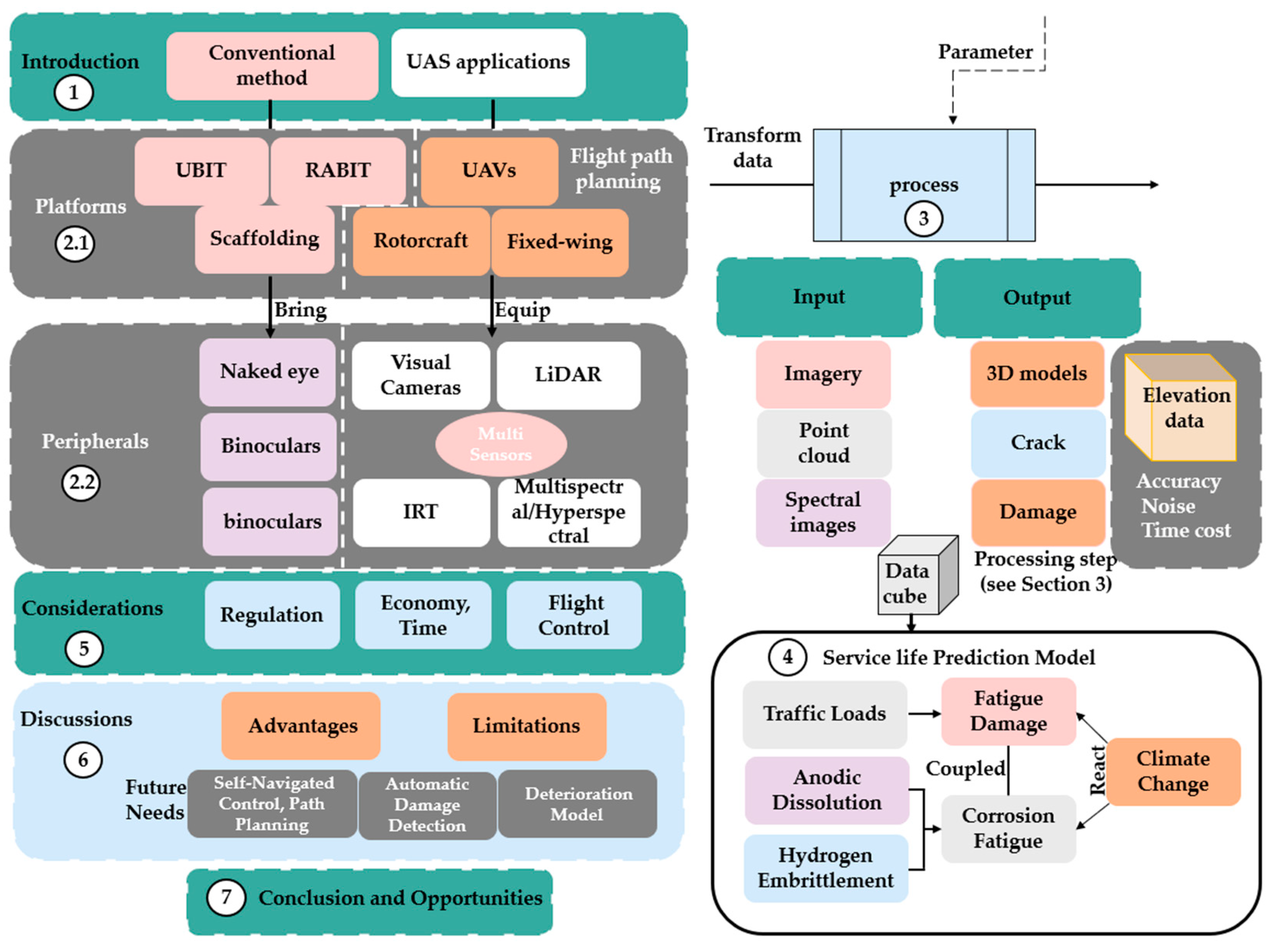

| Platforms | Ref. | Focus | Method | Main Advantages | Main Shortcomings |
|---|---|---|---|---|---|
| UBIT | [57] | Under bridge, bridge piers | Manual recording | Easy to implement, detect inaccessible areas | Expensive, threatened inspector’s security |
| RABIT | [58,59] | Bridge surface | Ultrasonic echo, vision | Labor saving, picture record | Deck inspections only |
| Fixed-wing UAV | [60] | Overall bridge | External sensor (s) | High efficiency, low cost, and labor saving | Hover-limiting |
| Rotorcrafts | [57,62,63,64,65] | Overall bridge | External sensor (s) | Hovering, no runway is required | Sensor weight restriction |
| UAVs fleet | [15] | Overall bridge | Multi-sensors | Various types of sensors | Hard to cooperate with different UAVs |
| Data Processing | Ref. | Focus | Required Time | Main Advantages | Main Shortcomings |
|---|---|---|---|---|---|
| 3D reconstruction | [43,64,98,99,100,101,102,103,104,105,106,107,108,109,110,111,112,113,114,115,116,117,118] | Imagery and point clouds data | Hour level | Complete bridge detection, detailed model generating | Time consuming, high precision required |
| Image-processing techniques | [88,89,90] | Imagery | Hour level | Scanning efficiency, overall point cloud data | Complicated, hard to select |
| Deep learning | [92,93,94,95,96,97,98,99,100,101,102,103,104,105,106] | Image dataset | Day level (model training) | High precision | Training model in advance |
| Threshold extraction | [14,49,96] | Spectral images | Hour level | Internal defect identification | Hard to extract threshold, sensitive to temperature |
Publisher’s Note: MDPI stays neutral with regard to jurisdictional claims in published maps and institutional affiliations. |
© 2022 by the authors. Licensee MDPI, Basel, Switzerland. This article is an open access article distributed under the terms and conditions of the Creative Commons Attribution (CC BY) license (https://creativecommons.org/licenses/by/4.0/).
Share and Cite
Li, H.; Chen, Y.; Liu, J.; Zhang, Z.; Zhu, H. Unmanned Aircraft System Applications in Damage Detection and Service Life Prediction for Bridges: A Review. Remote Sens. 2022, 14, 4210. https://doi.org/10.3390/rs14174210
Li H, Chen Y, Liu J, Zhang Z, Zhu H. Unmanned Aircraft System Applications in Damage Detection and Service Life Prediction for Bridges: A Review. Remote Sensing. 2022; 14(17):4210. https://doi.org/10.3390/rs14174210
Chicago/Turabian StyleLi, Hongze, Yanli Chen, Jia Liu, Zheng Zhang, and Hang Zhu. 2022. "Unmanned Aircraft System Applications in Damage Detection and Service Life Prediction for Bridges: A Review" Remote Sensing 14, no. 17: 4210. https://doi.org/10.3390/rs14174210
APA StyleLi, H., Chen, Y., Liu, J., Zhang, Z., & Zhu, H. (2022). Unmanned Aircraft System Applications in Damage Detection and Service Life Prediction for Bridges: A Review. Remote Sensing, 14(17), 4210. https://doi.org/10.3390/rs14174210