Article

Spatiotemporal Correlation between Artificially Triggered and Adjacent Natural Lightning Flashes

1
State Key Laboratory of Severe Weather, Chinese Academy of Meteorological Sciences, Beijing 100081, China
2
Collaborative Innovation Center on Forecast and Evaluation of Meteorological Disaster (CIC-FEMD), Nanjing University of Information Science & Technology, Nanjing 210044, China
3
Department of Atmospheric and Oceanic Sciences & Institute of Atmospheric Sciences, Fudan University, Shanghai 200438, China
*
Author to whom correspondence should be addressed.
Remote Sens. 2022, 14(17), 4214; https://doi.org/10.3390/rs14174214
Submission received: 1 August 2022 / Revised: 22 August 2022 / Accepted: 23 August 2022 / Published: 26 August 2022
(This article belongs to the Section Atmospheric Remote Sensing)

Abstract

:
A triggered lightning flash (TLF) provides a unique perspective on the relationship between spatiotemporal proximity flashes, owing to its determined location and time, convenient direction measurement, and explicit association with the charge region. In this study, 3-D lightning location, current measurement, and atmospheric average electric field (AAEF) data were used to investigate the spatiotemporal relationship of TLFs (68 samples in South China) with adjacent natural lightning flashes (NLFs). The TLF-related negative charge regions had an average core height of 5.2 km and ambient temperature of approximately −1.7 °C. The effective negative charge region (the charge density that was high enough for the occurrence of lightning discharge) can be approximately equivalent to a circle with an average diameter of 10.3 km. For approximately 93% of (all) the TLFs, no NLF channel (initiation) was located within 5 km of the flash-triggered position, within 5 s before and after their occurrence. In situations where spatiotemporally adjacent NLFs and TLFs occurred, they were either associated with different charge layers or the same charge layer but different charge positions. Most NLFs that caused significantly sharp AAEF changes just before or after the TLFs were not associated with the TLF-related negative charge. Therefore, the recovery of the AAEF, which has usually been referenced as the timing choice of the triggering operation, was not directly associated with the TLF-related charge region. The average interval between the TLFs and NLFs that occurred within 10 min before and after the TLFs and neutralized the TLF-related negative charge was approximately 145 s.

Graphical Abstract

1. Introduction

A triggered lightning flash (TLF) has various advantages, including predictable occurrence time, determinable grounding location, and convenient measurement. Its characteristics are similar to those of natural upward cloud-to-ground (CG) lightning, and its return stroke process is equal to the subsequent return stroke process of natural downward CG lightning, making it one of the important means to carry out research on lightning discharge mechanisms and protection technologies [1,2,3,4]. Some countries, such as the United States, France, Japan, China, and Brazil, have conducted artificially triggered lightning experiments for many years with fruitful results [5,6,7,8,9].
Currently, artificially triggered lightning technique is usually a “rocket-wire” approach, where a metal wire is dragged by a small, rapidly ascending rocket. The upper end of the wire is rapidly introduced into a strong electric field in space, breaking through the influence of the surrounding corona shield and triggering an upward leader propagating towards and then within the cloud. This process is referred to as the initial stage. Some TLFs comprise only the initial stages, whereas others comprise the initial stage and the following return strokes.
It is generally accepted that a TLF is conducted when the charge density and electric field are large enough to generate a natural lightning flash (NLF). Before the occurrence of the NLF, artificial intervention by rapidly introducing a wire into a strong electric field in the air is used to promote the initiation of discharge at the wire tip. The lightning channel and current are designed to traverse the length of the wire, making the measurement of direction possible. There is an empirically based view that NLF does not occur within a certain distance from a TLF for a certain time before and after the TLF, which indicates the spatiotemporal isolation of the TLF. Zhang et al. [10] suggested that the TLF should be conducted at the later stage of the atmospheric average electric field (AAEF) recovery, following the sharp decrease in AAEF caused by the NLF, with a sound-light difference of less than 10–15 s. Meanwhile, the AAEF recovery rate should be less than 50 V m−1 s−1 and the AAEF should be greater than 4 kV m−1 on the ground. In other words, there is no NLF at a distance of approximately 3.5–5 km from the flash-triggered position for some time before the triggering operation (they estimated it to be about teens of seconds according to the AAEF changes). They also pointed out that TLF could cause a significant reduction in lightning frequency and lightning-induced AAEF changes in the time immediately following the event, implying that charge neutralization caused by the TLF can affect the interval before the next NLF.
The empirically based view of the spatiotemporal isolation of TLFs also comes from the understanding of AAEF changes on the ground. For example, an artificially triggered lightning experiment conducted in South China [3,4] was mainly implemented in the stratiform of thunderstorms, because the lightning frequency in this area was relatively low and the AAEF change was more regular (Figure 1). This made it easier for researchers to respond quickly (just before the occurrence of possible natural lightning) and launch the rocket. In contrast, frequent lightning discharges in the convection zones of thunderstorms make it difficult to capture the timing of TLF. Furthermore, when the convection region, which typically featured a tripolar charge structure (upper positive, middle negative, and lower positive regions), was overhead, the AAEF at the ground was usually dominated by the middle negative region but was also impacted by the lower positive regions and charge carried by the precipitation. This might have caused AAEF waveform distortion and affected the judgement of triggering timing.
Although the spatiotemporal isolation of TLF is partly affected by human selection, the spatiotemporal relationship of TLFs with the NLFs that precede or follow them gives us a unique insight into the correlation between adjacent lightning flashes, and between lightning and charge structure. For example, in the AAEF waveform shown in Figure 1, it is generally accepted that the recovery of the electric field (EF) after the sudden change caused by the lightning corresponds to the enhancement of the charge density after it is neutralized and weakened by the lightning, thereby providing the conditions for the next lightning. However, neither analyses based on acousto-optic differences nor AAEF changes can clarify the specific locations of the lightning flashes and their associated charge regions. Therefore, it is difficult to clearly illustrate the spatiotemporal relationship of the TLFs with the NLFs, and their relationship to the charge regions. In this study, we mainly used 3-D location data of TLFs and NLFs to investigate the above-mentioned problems that have not yet been fully understood.

2. Data and Methodology

The data for the TLFs and NLFs were obtained from an experiment conducted in Guangdong, China from 2015 to 2019, including 3-D lightning location data, current measurement at the bottom of the TLF channels, AAEF data on the ground, and sounding data. These are described in detail below.

2.1. Observations and Measurements

2.1.1. Lightning Location

The 3-D positions of the TLFs and NLFs were provided by a low-frequency E-field detection array (LFEDA) in Guangdong. The LFEDA contains 10 detection substations, of which the SLC substation was relocated to the ZTC position in June 2017, as shown in Figure 2. LFEDA sensors are typical fast antennas [11] with a 1-ms time constant. The LFEDA detects the EF change signals caused by lightning discharges at 160 Hz−600 kHz, with a sampling rate of 10 M Sa s−1, and locates the positions of the channel breakdown discharges appearing as pulses on the EF waveforms using the time arrival difference method. Simultaneous records of at least five substations for one pulse are required to determine the 3-D location of the event. According to the locations of the LFEDA for the TLFs and a CG flash with multiple return strokes causing death, the LFEDA has a localization accuracy of approximately 100 m [12,13]. The original locations of the LFEDA are called “sources” here. Only sources with a chi-square goodness of fit of less than 5 and heights less than 20 km were chosen. The sources were grouped into flashes with an algorithm used in previous studies [12,14,15]; that is, a potential flash source must occur within 0.4 s of the previous source and within 4 km and 0.6 s of any other flash source.

2.1.2. Measurement of TLF Current

The TLF current was measured at the bottom of the channel using a coaxial shunt with a resistance of 1 mΩ and a bandwidth of 200 MHz. The lower end of the coaxial shunt was connected to a ground grid with ground resistance of 6.7 Ω. The voltage signal from the coaxial shunt was transmitted to a HBM Gen5i (14-bit) portable data recorder via an optical isolation system with a bandwidth of 25 MHz. Data acquisition was performed at a sampling rate of 10 M Sa s−1 and was simultaneously recorded in two channels with measuring ranges of ±2 and ±50 kA, respectively, to ensure the accuracy of both small and large discharge processes. More information on the artificially triggered lightning experiments in Guangzhou can be found in the articles by Zhang et al. [3] and Zheng et al. [4].

2.1.3. Observation of AAEF

AAEF was detected using a CS110 Electric Field Meter (Campbell Scientific Inc., Logan, UT, USA) at a sampling rate of 1 Sa s−1. Figure 1 shows an example of this recording. This equipment was located approximately 90 m from the flash-triggered position and was one of the most important references for determining the timing for the triggering of lightning.

2.1.4. Sounding Data

The sounding station in Qingyuan, which was located approximately 52.5 km west of the flash-triggered position (Figure 2), provided information of atmospheric stratification twice-daily (08:00 and 20:00, Beijing Time, the same as below) during the experiment. The sounding data immediately before the triggered lightning time was used to obtain the height of the isotherms.

2.2. TLF Data

To determine the LFEDA 3-D locations of the TLF, at least one source within 1 km radius of the flash-triggered point was required to correspond to the time of the TLF. The localization results were further confirmed by comparison with the current records in time. Figure 3 shows the LFEDA sources and the current waveforms of the TLF. The TLF extended its channels northward, eastward, and southward. Most sources were located at a height around 4.5 km (1 km statistical bin, representing a height range of 4–5 km, the same as below), corresponding to an ambient temperature of about 3 °C. This TLF contained a total of seven return strokes, and the LFEDA sources corresponded well to them (Figure 3e,f). The other LFEDA sources were associated with the initial upward leader and in-cloud breakdown processes between return strokes. The lightning duration obtained from the LFEDA sources was 931.4 ms (the time difference between the first and last sources) and that obtained from the current data was 949.3 ms (the start and end times were determined at the positions where the current signal was drowned in the noise and became indistinguishable). A total of 68 TLFs between 2015 and 2019 were included in the analysis.
When considering the spatial position of the TLF in relation to the NLF approaching the TLF in time and space, the extent of the lightning channels was analyzed based on the sources. Although there were no other observation means to judge whether the spatial extent of the lightning channel measured by the LFEDA was reliable, it can be judged from another angle by comparing the TLF duration suggested by the LFEDA and that of the current measurement. That is, if the LFEDA data can reasonably reflect the duration of the TLF, it is highly possible for the LFEDA to observe the entire TLF process relatively completely, and therefore to characterize the spatial extent of TLF. If this statement holds for TLFs, then we can assume that the LFEDA data can also reflect the spatial extent of the NLFs.
The scatter distribution and linear fitting of the durations suggested by the LFEDA and the current data are shown in Figure 4. The determination coefficient (R2) of 0.66 indicated a relatively strong correlation between the TLF durations suggested by the LFEDA and those suggested by the current measurements. Below ~0.8 s, the TLF duration suggested by the LFEDA tended to be smaller than that suggested by the current measurement, whereas the opposite was true above ~0.8 s. The reasons for this may be as follows. First, with low height and weak discharge, the initial upward leader of the TLF could be located by the LFEDA at a relatively low probability, which might cause the TLF duration suggested by the LFEDA to be low; this effect might be more accurate for the TLF lasting for a relatively short time. Second, some TLFs might include a long continuous current after the return stroke (Figure 3(f2)). For the continuous current, the corresponding EF pulse signal was relatively low, causing the weak detection ability of the LFEDA, and the possible underestimation of the duration. However, the continuous current mainly occurred in the existing channels; hence, the estimation of the spatial extent of the TLF from the LFEDA should not be remarkably affected. Third, TLFs with relatively long durations may contain rich intra-cloud discharge processes. The currents of some of these processes did not flow through the grounded channel of the TLFs, causing the absence of current measurements. However, the LFEDA was likely to detect these discharge processes, thereby providing a greater duration of TLFs than that provided by the current data. Statistically, LFEDA and current data provided the average TLF durations of 582.4 and 664.1 ms, respectively. From the above analysis, we believe that LFEDA data could provide reliable locations for intra-cloud breakdown discharge processes, and thus, its data could be used to characterize the spatial extent of lightning, which is predominantly determined by channels within the cloud.

3. Results and Analyses

3.1. TLF-Related Charge Region

All TLFs were negative in polarity, which means that the negative charges in the cloud were drained to the ground. The lightning channel typically propagates towards a region with high charge density; therefore, the concentration regions of the sources are usually the positions of the main charge regions involved in the discharges [14,16,17]. Therefore, by counting the peak heights of the TLF sources, we obtained the positions of the negatively charged core region in the vertical direction. 
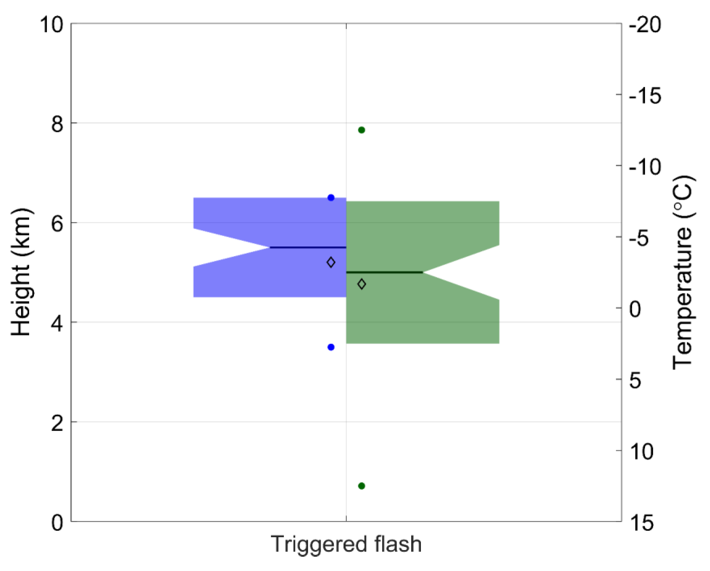
Figure 5 shows their distribution in terms of height and ambient temperature. The negative charge region associated with the TLF was predominantly distributed from 3.5 to 6.5 km in height, with an average height of 5.2 km and a median height of 5.5 km; the corresponding ambient temperatures were about 12.5 to −12.5, −1.7 and −2.5 °C, respectively. MacGorman et al. [18] analyzed the locations of three TLFs using a lightning mapping array in Florida and found that lightning channels mainly propagated in the negative charge region near the melting layers; the results of this study are in general agreement with their results.
The TLF source locations provide an approach for estimating the horizontal extent of the effective negative charge region (ENCR) associated with the TLF. The ENCR indicates the region where the charge density is sufficiently large to support the propagation of the TLF channels. The lightning channels propagate within a high-density charge region; therefore, some studies have used the spatial extent of lightning channels to characterize the size of the charge region [19,20,21,22,23,24,
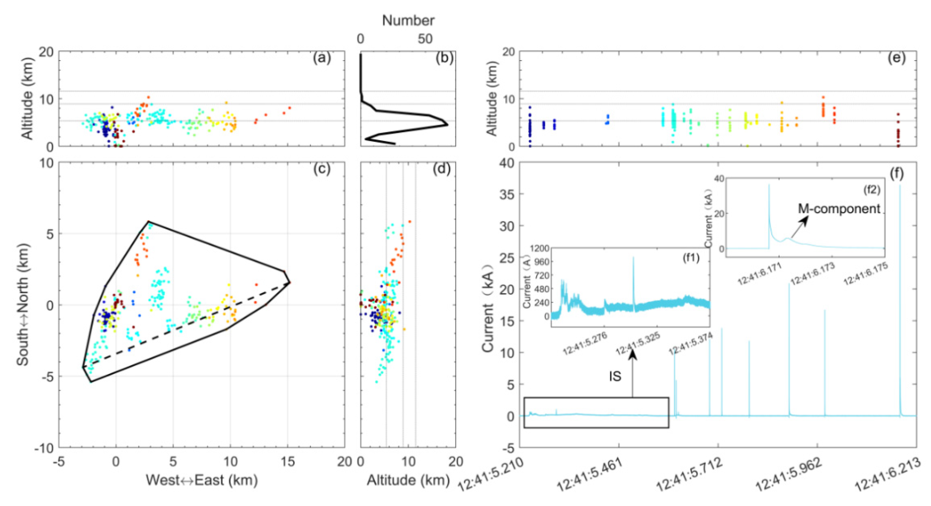
25]. We referred to some of the parameters used in the cited literature, such as the lightning length (the furthest distance of any two sources involved in a flash, indicated using dashed line in Figure 3c) and the lightning convex hull area (the convex hull is a polygon that delineates all the lightning sources with the smallest area, indicated by the polygon in Figure 3c). In the analysis, some sources that were manually discriminated to be beyond the lower charge region directly associated with the TLFs were excluded from the calculation. The horizontal extension length of the TLFs (ENCR) ranged from 2.1 to 26.1 km, with a mean of 9.1 km and a median of 8.1 km. With regard to the convex hull area, the corresponding values were from 2.6 to 451.9, 83.9, and 54.3 km2. If using a circle to represent the ENCR that had the same area as the convex hull, we would calculate the diameter of the ENCR to be 10.3 km (mean) and 8.3 km (median), close to the ENCR horizontal extension length indicated by the TLF length.

3.2. Spatiotemporal Isolation of TLFs

We first looked for NLFs at 1 km intervals within a range of 1–15 km radii from the flash-triggered point within 3, 5, 7, and 10 s before and after the TLFs. There were two scenarios: (1) the lightning channel entered the corresponding areas; and (2) the lightning was initiated in the corresponding areas. Based on previous studies, lightning initiation was considered as the first source of LFEDA lightning [12,14]. The subjects in the statistics were TLFs. That is, for a TLF, as long as a situation corresponding to (1) or (2) existed in the determined spatiotemporal range, it was recorded as one event, regardless of the number of NLFs (but should be greater than zero). We also used the term “event” for the relevant description.
Figure 6 shows the number of events at different distances from the flash-triggered position (from 1 to 15 km with a 1 km bin) and different statistical time (3, 5, 7, and 10 s before and after the TLFs). Events meeting the above conditions grew with an increase in the statistical time and distance range. Meanwhile, the increasing tendencies of the event number were greater in the ranges far from the flash-triggered position. The increase speeds within the 5 km range were apparently slower than those outside the 5 km range, as the distance from the flash-triggered position increased. In the case of the NLF channel entering the investigated areas within 3, 5, 7, and 10 s before the TLF, the increase rates of the number of events within 5 km were 0.4, 0.6, 0.8 and 1.4 per km, respectively, compared with 1.0, 1.8, 2.3, and 3.0 per km, respectively, in the range of 5−15 km. For the case of the NLF channel entering the investigated areas within 3, 5, 7, and 10 s after the TLF, the increase rates of the number of events were 0.4, 0.4, 0.4, and 0.8 per km within 5 km, respectively, and 1.4, 1.9, 2.2, and 3.0 per km in the range of 5–15 km, respectively.
Thus, the range of 5 km from the flash-triggered position can be regarded as a region that reflects the isolation of the TLFs in space. Two, three, four, and seven events with NLF channels entered this area within 3, 5, 7, and 10 s before the TLFs accounted for approximately 2.9%, 4.1%, 5.9%, and 10.3% of the TLF samples, respectively. The corresponding values were 2, 2, 2, and 4 events, and approximately 2.9%, 2.9%, 2.9%, and 5.9% of the sample, respectively, within 3, 5, 7, and 10 s after the TLFs.
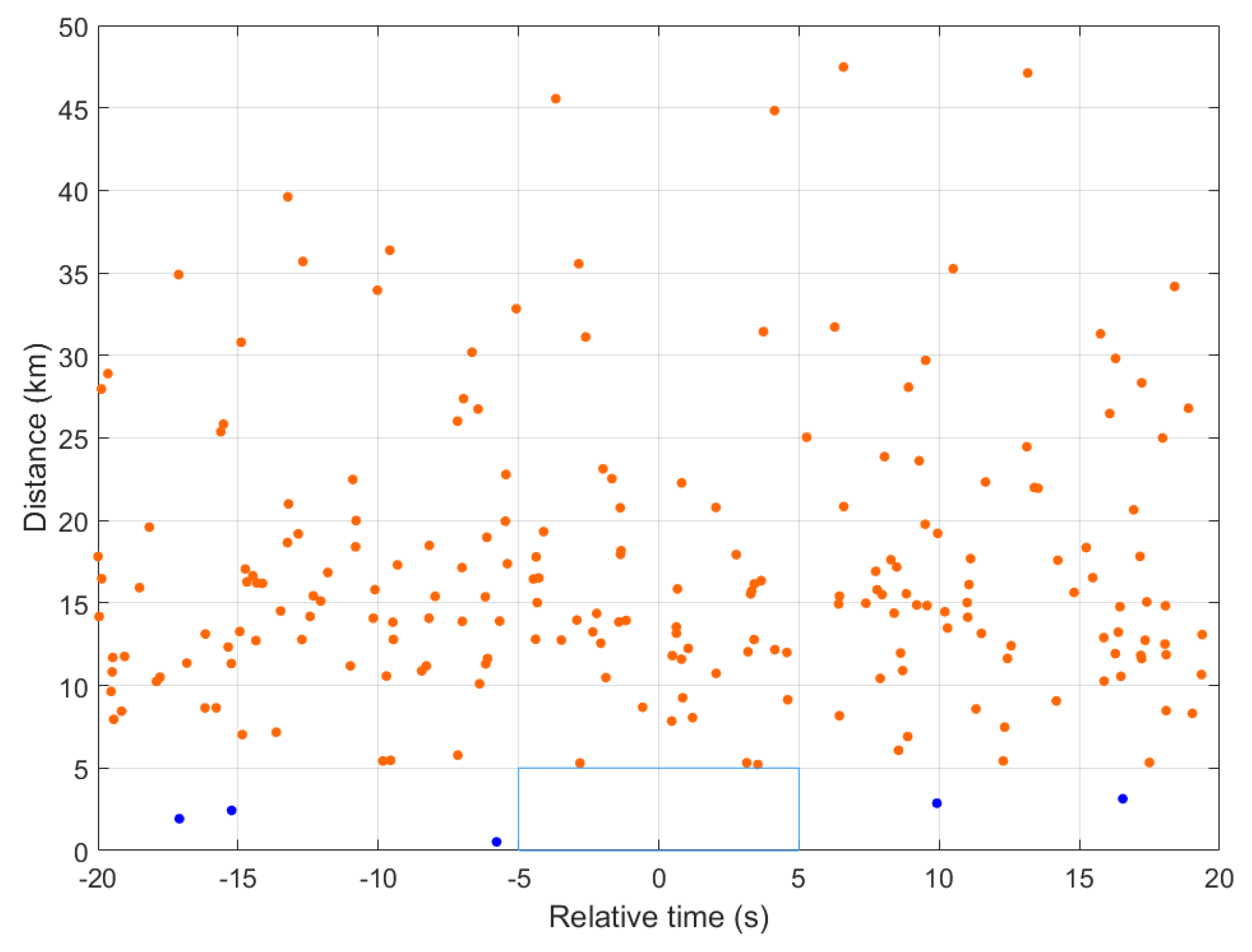
Figure 7 shows the scattered initiation points of the NLFs at a distance from the flash-triggered position and time from the TLF. In terms of distance, 5 km was still a relatively evident demarcation; in the statistical time range of 20 s before and after the TLFs, the events corresponding to the NLFs initiated within and beyond 5 km were the least and most in number, respectively. For the 68 TLFs, there was no corresponding NLF initiated within a 5 km radius from the flash-triggered position, and within 5 s before and after their occurrence. At 10 and 20 s before the TLFs, there were one and three events in which the initiations of NLFs were located within a 5 km radius of the flash-triggered position. In the 20 s after the TLF, there was one event in which one TLF corresponded to two NLFs initiated within 5 km distance of the flash-triggered position.
According to the above analysis, a time of 5 s and spatial distance of 5 km were able to describe the spatiotemporal isolation of approximately 93% of the TLFs. The temporal parameter of 5 s was significantly smaller than the 10 s estimated by Zhang et al. [10] based on the change in AAEF, whereas the spatial distance of 5 km was close to the upper end of their estimation values based on acousto-optic differences. In addition, it is interesting to note that some NLFs could still occur very close to TLFs spatiotemporally. Further analyses will be conducted on these cases.

3.3. Scenario That NFL Channels Entered into a 5 km Radius from the Flash-Triggered Position within 5 s before and after the TLFs

There were a total of five TLFs within 5 s before and after that the channels of the five NLFs propagated within a 5 km radius from the triggered lightning point. In three events, the NLFs occurred before the TLFs, and in the other two, after the TLFs.
The horizontal and vertical distributions of the sources of the three TLFs and their corresponding NLFs are shown in Figure 8. As previously mentioned, the peak height of the sources was referred to as the position of the charge region core where lightning discharges were involved. The TLFs were all negative, thus, the intra-cloud channels directly associated with them should propagate in the negative charge region. Therefore, the peak heights of their sources generally represent the position of the negative charge core. For NLFs, at least two opposite-polarity charge zones are involved in the discharges, because of the bidirectional propagation of leaders [14,25,26,27]. The height distributions of the sources displayed one or two main peaks. One peak typically corresponded to the core position of one of the main charge regions, and two peaks possibly corresponded to the positions of the two main charge regions [14,16,17].
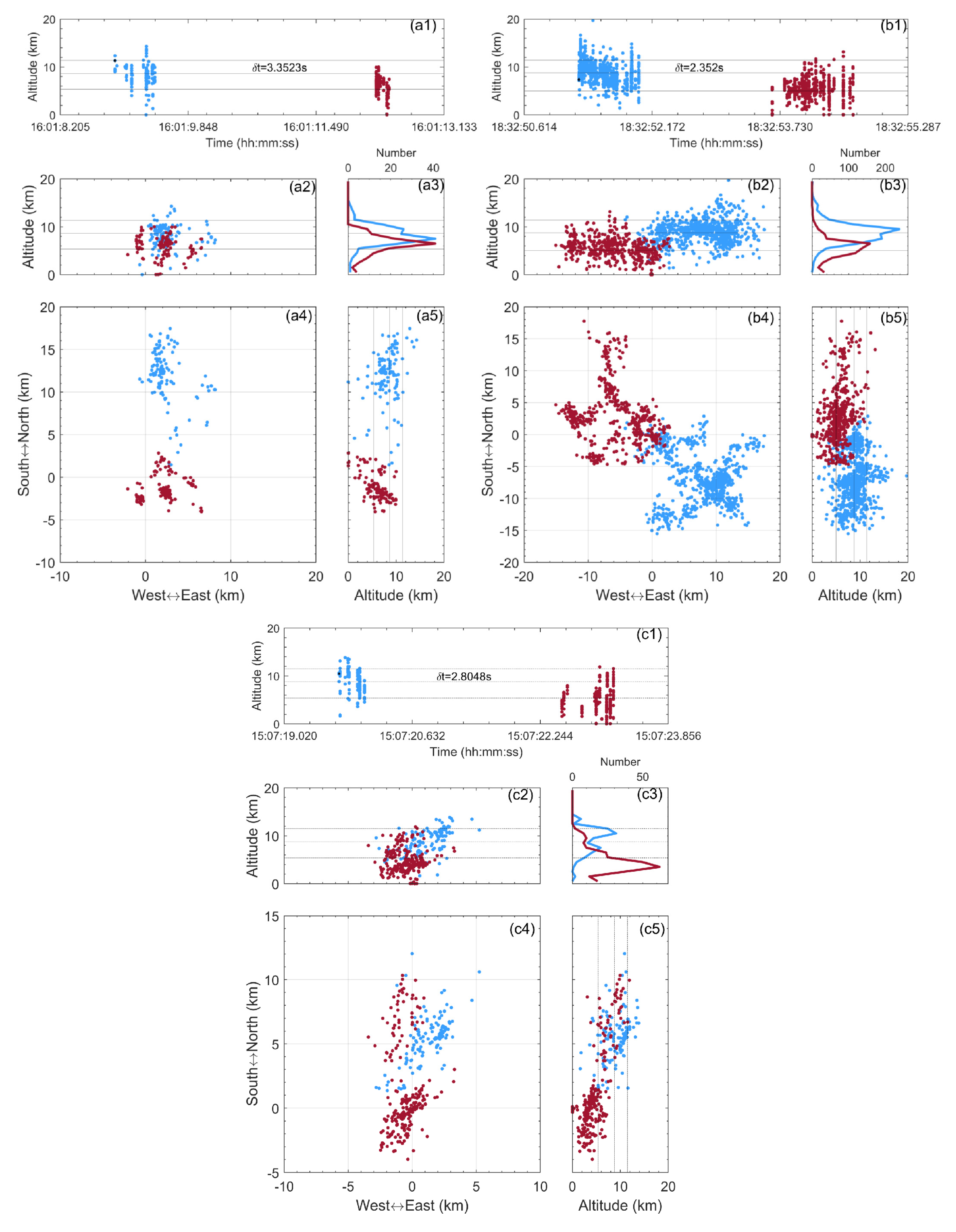
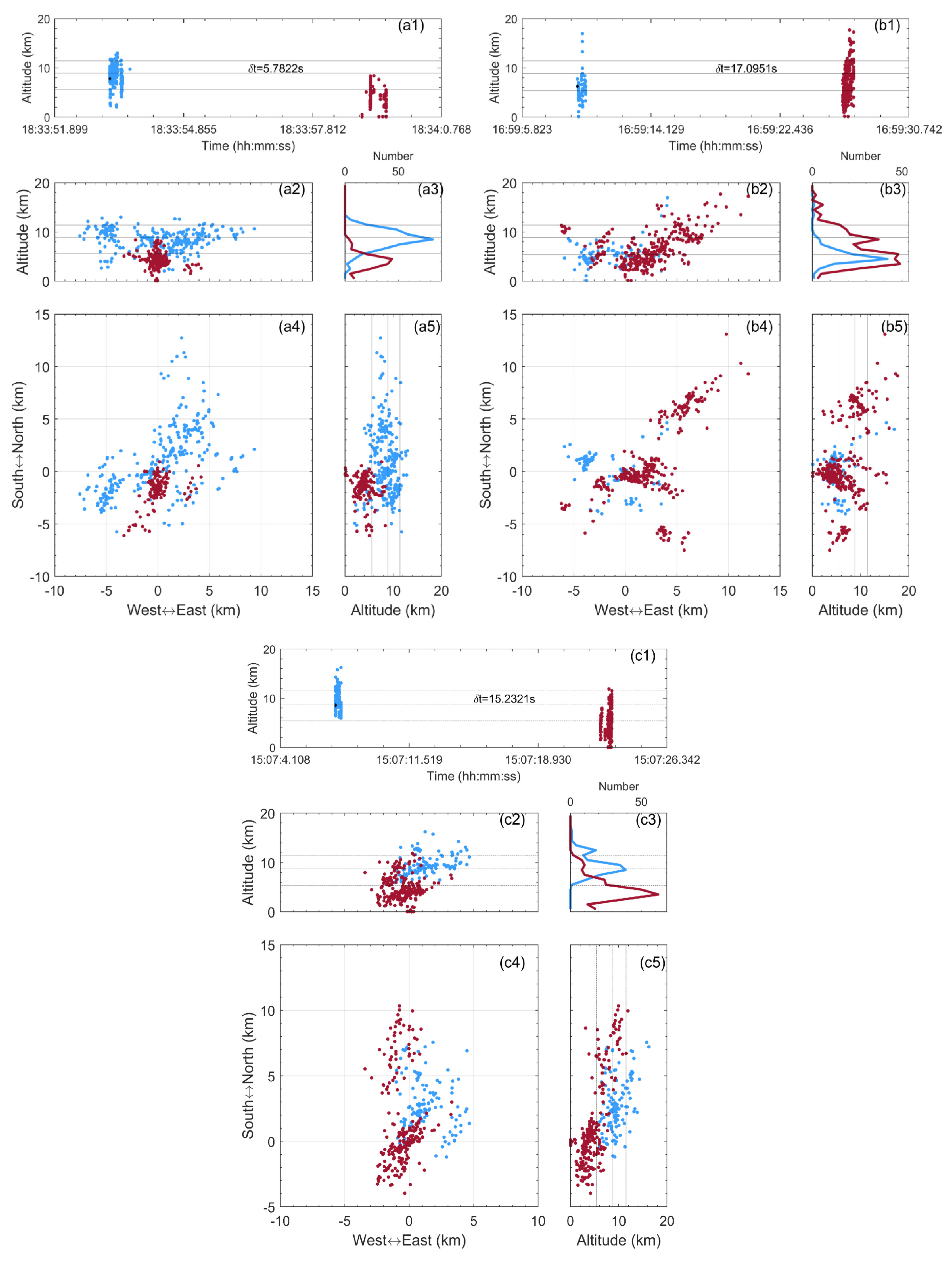
One NLF occurred approximately 3.35 s before the TLF named T20150612160111, and its channels propagated approximately 3.20 km from the flash-triggered position (Figure 8a). The height of the negatively charged core associated with the TLF was 6.5 km, corresponding to an ambient temperature of approximately −8 °C. The peak height of the NLF sources was located at 7.5 km or an ambient temperature of approximately −14 °C. There was a large overlap between the NLF and TLF sources in height (Figure 8(a3)), implying that there might be a charge layer involved in both the discharges of the NLF and TLF. However, by checking the 3-D spatial distribution of their sources, we found that the channels of the TLF and NLF were separated from each other. In the horizontal plane (Figure 8(a4)), the NLF channels were mainly located north of the flash-triggered position, whereas the TLF channels mainly propagated southward. These results suggest that the NLF and subsequent TLF might neutralize the charges at different positions, although some of these charges might occur in the same charge layer.
The second case corresponded to the TLF named T20150813183254, which was approximately 2.35 s preceded by an NLF whose channels propagated to a position approximately 0.40 km from the flash-triggered position (Figure 8b). The NLF and TLF showed spatial separation in the horizontal distributions of their channels (Figure 8(b4)). Most of the NLF channels appeared to the southeast of the flash-triggered position, whereas the TLF channels mainly propagated westward and northward. According to Figure 8(b3), the peak source height of the NLF was located at 9.5 km (ambient temperature of approximately −25 °C), significantly higher than that of its TLF (about 6.5 km and −7 °C level, respectively). There were both TLF and NLF channels between 0 and −20 °C levels, but their horizontal areas were significantly different. Above the flash-triggered position, the TLF and NLF partially overlapped in their horizontal distributions (Figure 8(b4)), but the NLF sources were generally higher than the TLF sources, with the NLF sources within a 2 km radius of the flash-triggered position having a peak height of 9 km, while the TLF turning its channel direction from upward to horizontal at approximately 5 km (Figure 8(b2,b5)). Therefore, the lower negative charge region associated with this TLF might also be involved in the discharges of the NLF, but charges neutralized by them should be in different horizontal positions.
Figure 8c shows the third TLF (named T20170710150722) and an NLF occurring approximately 2.80 s before it, the channels of which propagated at the nearest about 1.68 km from the flash-triggered position. In the plan view (Figure 8(c4)), the NLF was located in the area to the north of the flash-triggered position, while the main part of the TLF was located near to and south of the flash-triggered position; some sources were also located north of the flash-triggered position. The northern sources were grouped into TLF using the flash algorithm. However, they were predominantly distributed between 0 and −40 °C isotherms, with the peak height being 9.5 km (about −20 °C level), significantly different from the sources around the flash-triggered position, which were mainly distributed under the 0 °C isotherm and had a peak height of 3.5 km. Therefore, these two sources should correspond to layers with different charge layers. The current data suggest that this TLF is negative in polarity, and considering that the northern sources were visually separated from the sources around the flash-triggered position, we speculated that the northern sources might belong to a flash that was induced by the abrupt EF change in the cloud caused by the TLF (because the northern sources were relatively later in the time sequence) or a standalone intra-cloud flash that partly coincided with the TLF in time. We then considered the sources around the flash-triggered position as the body of the TLF. The spatial distributions of the NLF and TLF showed that they were generally separated from each other in both the horizontal and vertical directions. The NLF was mainly located to the north of the TLF, with two peak source heights (main peak of 10.5 km and secondary peak of 7.5 km) that were significantly higher than the source peak height of the TLF (3.5 km). Therefore, it was deduced that the TLF and NLF neutralized the charges in the different charge layers. The northern sources that were grouped into the TLF by the flash algorithm coincided with those of the NLF in height, but they were separated in the horizontal plane, indicating their association with the same charge layers but different charge positions.
There were two TLFs, after which the channel of the two natural lightning flashes propagated into the 5 km radius of the flash-triggered position within 5 s. The TLF named T20160614183449 was followed 3.54 s later by an NLF, the nearest distance of which from the flash-triggered position was 4.97 km. The LFEDA located only 12 sources for this natural lightning, which are not shown here. These sources were distributed between 6.5 and 9.5 km in height, corresponding to the levels between approximately −6 and −25 °C. The horizontal extension was approximately 1 km. Therefore, the channel of this NLF developed predominantly in the vertical direction, indicating that this NLF might have just developed an initial leader [14]. The core of the sources of this TLF was at 5.5 km in height, corresponding to an ambient temperature of approximately −1 °C. There was a clear spatial separation of the TLF from the NLF in both height and horizontal positions, implying that they were formed by different charge layers.
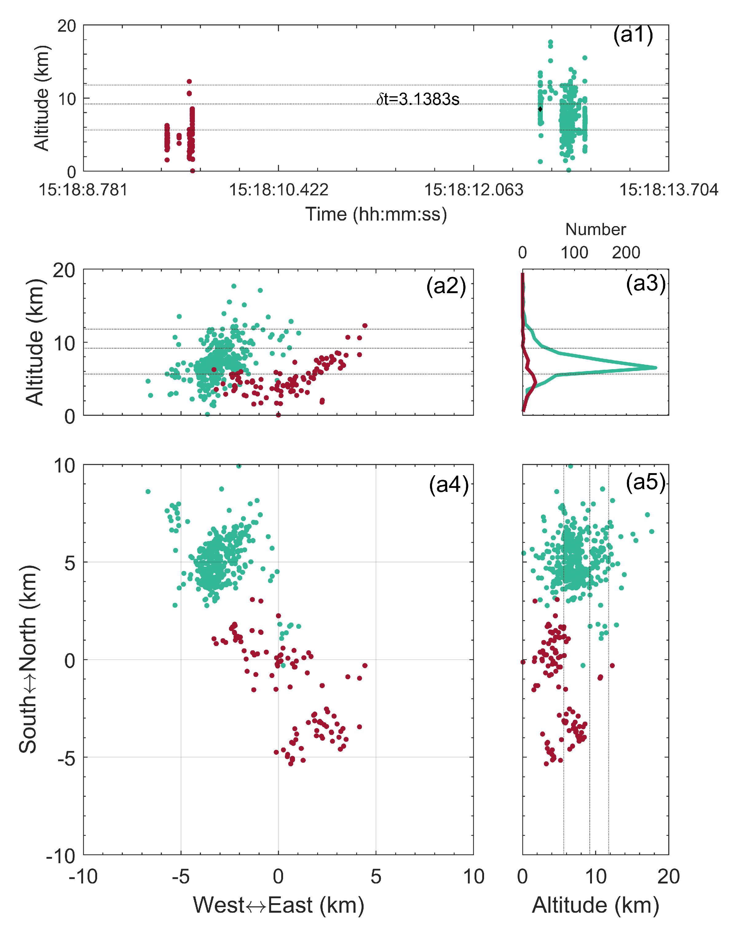
Figure 9 shows the TLF named T20190702152112 and the subsequent NLF that occurred 3.14 s after it. The NLF channels propagated to the nearest 0.39 km from the flash-triggered position. In general, the TLF and NLF occurred in different spatial regions. The NLF sources were located northwest of the flash-triggered position and had a peak height of 6.5 km. The TLF propagated its channels towards the northwest and southeast, with the latter being the main direction. The northwestern channels of the TLFs did not overlap with those of the NLF in the horizontal and vertical directions. The peak height of the TLF sources was located at 4.5 km, with the main parts of the sources near the flash-triggered position being below the 0 °C layer, and the southern parts being below −20 °C layer. In the vicinity of the flash-triggered position, some of the TLF and NLF sources coincided horizontally, but they were apparently vertically separated. Therefore, the NLF and TLF should occur in different charge layers near the flash-triggered positions.

3.4. Scenarios Where NFLs Were Initiated within a 5 km Radius from the Flash-Triggered Position within 20 s before and after the TLFs

There were a total of four TLFs that corresponded to five NLFs initiated within a 5 km radius of the flash-triggered position and within 20 s before and after the TLFs. Among the NLFs, three appeared before three TLF and two appeared after the same TLF.
Figure 10a shows the TLF named T20160609183358; the NLF initiated at 0.52 km from the flash-triggered position and 5.78 s before the TLF. They had an evident overlap in the horizontal distribution (Figure 10(a4)), but a difference in the height distribution (Figure 10(a2,a3,a5)). First, the sources of the NLF were mostly concentrated around a height of 8.5 km, corresponding to an ambient temperature of about −18 °C, while most of the sources were located above the 0 °C layer. In contrast, the peak height of the TLF sources was 4.5 km, corresponding to an ambient temperature of approximately 3 °C, whereas most of the sources were located below the 0 °C isotherm. Above the flash-triggered position, the TLF sources mainly occurred below 6 km, whereas the NLF sources were generally above this height. Therefore, the TLF and NLF should be associated with different charge layers.
An NLF was initiated approximately 1.93 km from the flash-triggered position and 17.10 s before the TLF named T20160615165926, as shown in Figure 10b. Their channels clearly overlapped in the horizontal and vertical directions. The TLF sources were mostly concentrated at a height of 3.5–5.5 km, or an ambient temperature of approximately 11 to −1 °C. Meanwhile, some sources grouped into the TLF were located at higher positions and caused a second concentration height of 8.5 km, corresponding to an ambient temperature of about −18 °C. Furthermore, there were some sources above 8.5 km. The wide vertical distribution of sources associated with TLF indicates that multiple charge layers might have been involved. Because of the negative polarity of the TLF, it was indicated that the sources located at relatively high positions might belong to the discharges induced by the TLF (their time was behind the initiation of the TLF), or a single flash partially coinciding with the TLF in time but were grouped into the TLF by the flash algorithm, similar to the TLF shown in Figure 8c. In addition to the intersection of the TLF and NLF channels in the horizontal plane, the sources of the NLF peaked at a height of 4.5 km, falling in the peak height range of the TLF sources. Therefore, the lower negative-charge region associated with the TLF took part in the previous NFL discharge. A time interval of 17.10 s between them indicated the recovery time of the lower negative charge. The ground electric field recorded the AAEF change caused by natural lightning 17 s before the AAEF change caused by the TLF; however, the former AAEF change was small (not the same magnitude as the AAEF change corresponding to the TLF).
The NLF shown in Figure 10c was initiated at approximately 2.43 km from the flash-triggered position and 15.23 s before the TLF. The TLF was the same as that shown in Figure 8c, and the sources around the flash-triggered position were considered to be the body of the TLF. The NLF sources suggested two distribution peaks in height: the main peak at 8.5 km (approximately −18 °C) and the second peak at 12.5 km (approximately −49 °C), respectively, apparently different from the 3.5 km peak height (approximately 9 °C) of the TLF sources. Therefore, the NLF and TLF should be associated with different charge layers.
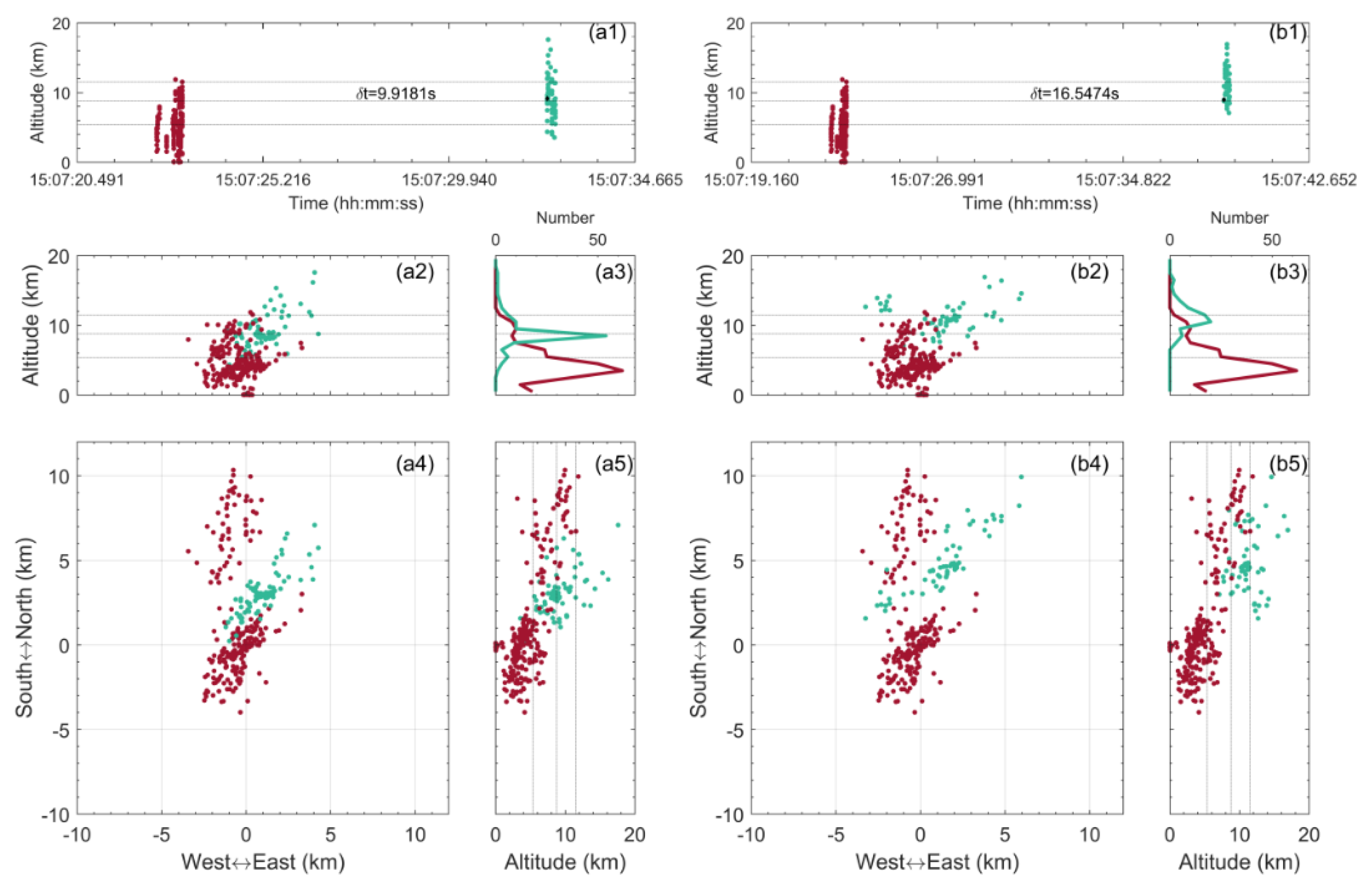
The TLF shown in Figure 11 was similar to the case shown in Figure 8c and Figure 10c. It was followed by two NLFs initiated at a horizontal distance of about 2.87 and 3.14 km from the flash-triggered position at approximately 9.92 and 16.55 s after the TLF, respectively. In terms of the distribution of the sources in height, the two NLFs had the peak heights of 8.5 km (approximately −18 °C) (Figure 11a) and 10.5 km (approximately −32 °C) (Figure 11b), respectively, significantly higher than the 3.5 km (about 9 °C) peak height of the TLF sources. Based on the horizontal and vertical distributions of the body of the TLF and the two NLFs, we deduced that the TLF corresponded to a charge layer different from the NLFs. Furthermore, the two NLFs probably originated from adjacent areas.

4. Discussion

The analysis showed that the spatiotemporal isolation of TLF was an objective existence, and it had two aspects. First, for approximately 93% of TLFs conducted in South China, there was no NLF in which the channels entered a 5 km radius from the flash-triggered position within 5 s before and after they occurred. For all TLFs, there was no NLF initiated within a 5 km distance from the flash-triggered position within a 5 s time range before and after their occurrence. The 5 km radius threshold was comparable to that estimated by Zhang et al. [10], but the 5 s time threshold was significantly smaller than their estimation of teens of seconds. Second, when TLFs and NLFs commonly occurred in adjacent time and space, we found that they might be associated with different charge layers, or the same charge layers but different charge positions. This is also a type of isolation of the TLF but has not been reported in previous studies.
For the second case mentioned above, the complex charge structure in the stratiform of the thunderstorm (overwhelming majority of TLFs were conducted in the stratiform region) might contribute to this. Stolzenburg et al. [28] observed six charge layers alternating in polarity in the region outside the convective zone of mesoscale convective systems, which is more complicated than the four charge layers in the convection region. The complicated stratiform charge structure makes it possible for the spatiotemporally adjacent TLF and NLF to be associated with different charge layers, even when they coincide horizontally. On the other hand, despite the local charging process, the main charges in the stratiform of the thunderstorm originate from the transport of charged particles from the convective region [7,29], which makes it possible that the charge density in the stratiform is not even. That is, the areas with a charge density high enough to support the lightning discharge are separated by regions with a relatively small charge density, although these areas may have the same polarity. This charge distribution pattern creates a condition where the spatiotemporally adjacent TLF and NLF can share the same charge layer but are associated with different charge positions.
Our previous knowledge of the temporal isolation of the TLF is based on the analysis of the change in AAEF, similar to that of Zhang et al. [10]. As shown in Figure 1, the time intervals between the sharp AAEF change caused by the TLF and the adjacent front and back sharp AAEF changes that had a magnitude comparable to that of the TLF were considered to represent the temporal isolation of the TLF. The TLF was conducted when the AAEF following the former sharp change increased to a level close to that just before the former NLF, because it was speculated that the recovery of the AAEF was associated with the charge increase after it was neutralized by the NLF. Specifically, the charge consumed by the NLF and the subsequent recovery was subjectively assumed to occur in the TLF-related charge region. The observation of AAEF cannot provide spatial position information of lightning; therefore, this view has not been tested. Here, we employed a further comparison of AAEF and LFEDA location data to clarify this speculation.
We first calculated the time intervals between the sharp AAEF changes caused by TLF and its front and back sharp AAEF changes. Notably, we stipulated that the magnitude of the sharp AAEF changes associated with the NLFs needed to be comparable to those associated with the corresponding TLFs, because this was also the reference in the actual operation of the triggering lightning experiment. AAEF changes that were smaller in magnitude than those associated with TLFs and those that did not shift the recovery tendency of the AAEF were neglected in determining the triggering timing. The AAEF waveforms associated with the 60 TLFs were investigated because they had an accurate time corresponding to the TLFs. The time intervals before (after) the TLFs varied between 6 and 298 s (between 10 and 240 s) and had a mean value of 81 s (79 s) and a median of 58 s (67 s). On the one hand, all time intervals were greater than 5 s, indicating that the NLFs shown in Figure 8 and Figure 9 did not cause significant AAEF changes. We further checked the AAEF change waveforms associated with these NLF, which caused only minor AAEF changes. On the other hand, when referring to the average values of the time intervals (approximately 80 s according to the mean and median values), approximately 51% (54%) of the analyzed TLFs corresponded to NLFs in which the channels propagated into a 5 km radius of the flash-triggered position within 80 s before (after) they occurred. These results showed that there was a large uncertainty in characterizing the spatiotemporal relationship between TLFs and adjacent NLFs when only using the abrupt change signal of the AAEF.
We then selected the LFEDA locations of the NLFs, causing the apparent sharp AAEF changes adjacently before and after the TLFs, and checked whether their channels clearly propagated into a height where the negatively charged region indicated by the TLF sources was located. Notably, we mandated that the NLF channels enter the height range of the TLF-related negative charge; however, we did not stipulate their partial coincidence with TLF channels in the horizontal range. However, if the NLF channels enter the 10 km radius of the flash-triggered position, we roughly determined that this NLF was associated with the lower negative charge region, and this charge region belonged to the TLF-related charge layer. A total of 41 (47) NLFs were chosen before (after) the corresponding TLFs. Among them, 14 (21) NLFs were found to be associated with a lower negative charge region, and 5 (7) NLFs entered the 5 km radius of the flash-triggered position. In addition, the channels of all NLFs did not coincide with those of the TLFs in the horizontal plane. These results suggest that most of the NLFs causing the sharp changes in AAEF adjacently before and after the TLFs were not directly associated with the charge contributing to TLFs. Under these circumstances, the recovery of the AAEF after the NLF was not directly related to the charge increase of the TLF-related negative charge.
Thus, our results raise a new question on the time interval between two adjacent flashes that were both formed by a lower negative charge region. Then, we looked for the NLFs in which the channels at least partly coincided with the TLF channels in 3-D space, forward and backward from the TLF time, with the time difference being limited to 10 min. A total of 50 (30) NLFs associated with the TLF-related negative charge region were found before (after) TLFs. The time intervals from the NLFs to the TLFs ranged from approximately 14 s to 456 s (from 18 s to 426 s), with a mean value of 144 s (146 s) and a median value of 109 s (113 s). Therefore, from the perspective of the TLF-related negative charge, the average charge recovery time was approximately 145 s (referring to the mean and median values) based on the NLF samples within 10 min before and after the TLFs; this time was larger than that previously estimated based on the AAEF changes (see the statistics in previous paragraphs and Zhang et al. [10]).
The spatiotemporal isolation of the TLF essentially reflects the spatiotemporal relationship between adjacent flashes, which should also exist between adjacent NLFs. For example, we can expect that two temporally adjacent NLFs are associated with different charge layers or positions. The TLFs were predominantly located in the stratiforms of thunderstorms; therefore, some of the parameters describing the spatiotemporal isolation of TLF may be suitable for natural lightning in stratiform regions. In the convection region, the charging rate and lightning frequency are typically higher and the parameters should be different.

5. Conclusions

In this study, the spatiotemporal relationship between TLFs (68 samples) and the NLFs that were spatiotemporally adjacent to them was investigated mainly based on the 3-D locations of the LFEDA in South China.
All the TLFs that predominantly occur in the stratiform of thunderstorms were associated with the lower negative charge regions, the core height (indicated by the peak height of the TLF sources) of which ranged from 3.5 to 6.5 km, with an average height of 5.2 km, corresponding to ambient temperatures from 12.5 to −12.5, and −1.7 °C, respectively. The TLFs had horizontal extension lengths ranging from 2.1 to 26.1 km, with a mean of 9.1 km, and convex hull areas ranging from 2.6 to 451.9 km2, with a mean of 83.9 km2, indicating the TLF-related ENCR could be approximately equivalent to a circle with an average diameter of 10.3 km.
It was found that for approximately 93% of the TLFs, no NLF propagated the channel in a 5 km radius from the flash-triggered position within 5 s before and after their occurrence; meanwhile, no NLF was initiated within a 5 km radius from the flash-triggered position within 5 s before and after all the TLFs. Furthermore, the isolation of TLFs took another form, that is, for the situation where there were spatiotemporally adjacent NLFs to the TLFs (specifically corresponding to the channels (initiation) of the NLFs entering a 5 km distance from the flash-triggered position within 5 s (20 s) before and after the TLFs in this study), they were associated with either different charge layers or the same charge layer but different charge positions.
It was found that most of the NLFs, which caused the sharp changes in AAEF having the same magnitude just before or after the TLF-related sharp changes of AAEF, were not associated with the TLF-related negatively charged region. Therefore, the recovery of the AAEF after the NLF-related sharp change in AAEF did not correspond to an increase in the charge in the TLF-related charge region (a previous experience-based view). In the investigated triggering lightning operations, the average interval time between the TLFs and NLFs that occurred within 10 min before and after the TLFs and neutralized the TLF-related negative charge was approximately 145 s.

Author Contributions

Conceptualization, D.Z.; Data curation, X.L., D.Z., Y.Z. (Yang Zhang) and X.F.; Formal analysis, X.L. and D.Z.; Funding acquisition, D.Z. and W.L.; Investigation, D.Z., Y.Z. (Yang Zhang), Y.Z. (Yijun Zhang), W.L., W.Y. and Y.F.; Methodology, X.L. and D.Z.; Project administration, D.Z. and W.L.; Resources, D.Z., Y.Z. (Yang Zhang), X.F., W.L. and Y.F.; Software, X.L. and X.F.; Supervision, D.Z. and W.L.; Validation, X.L. and X.F.; Visualization, X.L. and D.Z.; Writing—original draft, X.L. and D.Z.; Writing—review & editing, D.Z. and Y.Z. (Yang Zhang). All authors have read and agreed to the published version of the manuscript.

Funding

This research was funded by the National Key Research and Development Program of China (2017YFC1501503) and Basic Research Fund of CAMS (2020Z009).

Data Availability Statement

The data associated with this paper can be accessed on https://doi.org/10.5281/zenodo.6940711 (accessed on 29 July 2022) or from the corresponding author.

Conflicts of Interest

The authors declare no conflict of interest.

References

  1. Qie, X.; Zhao, Y.; Zhang, Q.; Yang, J.; Feng, G.; Kong, X.; Zhou, Y.; Zhang, T.; Zhang, G.; Zhang, T.; et al. Characteristics of triggered lightning during Shandong artificial triggering lightning experiment (SHATLE). Atmospheric Res. 2009, 91, 310–315. [Google Scholar] [CrossRef]
  2. Rakov, V.A.; Uman, M.A.; Rambo, K.J.; Fernandez, M.I.; Fisher, R.J.; Schnetzer, G.H.; Thottappillil, R.; Eybert-Berard, A.; Berlandis, J.P.; Lalande, P.; et al. New insights into lightning processes gained from triggered-lightning experiments in Florida and Alabama. J. Geophys. Res. Earth Surf. 1998, 103, 14117–14130. [Google Scholar] [CrossRef]
  3. Zhang, Y.; Yang, S.; Lu, W.; Zheng, D.; Dong, W.; Li, B.; Chen, S.; Zhang, Y.; Chen, L. Experiments of artificially triggered lightning and its application in Conghua, Guangdong, China. Atmos. Res. 2014, 135–136, 330–343. [Google Scholar] [CrossRef]
  4. Zheng, D.; Zhang, Y.; Zhang, Y.; Lu, W.; Yan, X.; Chen, S.; Xu, L.; Huang, Z.; You, J.; Zhang, R.; et al. Characteristics of the initial stage and return stroke currents of rocket-triggered lightning flashes in southern China. J. Geophys. Res. Atmos. 2017, 122, 6431–6452. [Google Scholar] [CrossRef]
  5. Fieux, R.; Gary, C.; Hubert, P. Artificially triggered lightning above land. Nature 1975, 257, 212–214. [Google Scholar] [CrossRef]
  6. Horii, K. Experiment of artificial lightning triggered with rocket. Mem. Fac. Eng. Nagoya Univ. 1982, 34, 77–112. [Google Scholar]
  7. Liu, X.; Wang, C.; Zhang, Y.; Xiao, Q.; Wang, D.; Zhou, Z.; Guo, C. Experiment of artificially triggering lightning in China. J. Geophys. Res. Earth Surf. 1994, 99, 10727–10731. [Google Scholar] [CrossRef]
  8. Newman, M.M.; Stahmann, J.R.; Robb, J.D.; Lewis, E.A.; Martin, S.G.; Zinn, S.V. Triggered lightning strokes at very close range. J. Geophys. Res. Earth Surf. 1967, 72, 4761–4764. [Google Scholar] [CrossRef]
  9. Saba, M.M.F.; Solórzano, N.N.; Pinto, O., Jr.; Eybert-Berard, A. Preliminary studies on the relationship between light and current intensity of triggered lightning. In Proceedings of the Proceedings, International Conference on Grounding and Earthing and 3rd Brazilian Workshop on Atmospheric Electricity, Rio de Janeiro, Brazil, 4–7 November 2002. [Google Scholar]
  10. Zhang, Y.; Yan, M.; Wang, C.; Liu, X. The conditions of artificially triggered lightning and probable effect on the characteristics of thunderstorm. Plateau Meteorol. 1992, 11, 178–185. [Google Scholar]
  11. Krehbiel, P.R.; Brook, M.; McCrory, R.A. An analysis of the charge structure of lightning discharges to ground. J. Geophys. Res. 1979, 84, 2432–2456. [Google Scholar] [CrossRef]
  12. Shi, D.; Zheng, D.; Zhang, Y.; Zhang, Y.; Huang, Z.; Lu, W.; Chen, S.; Yan, X. Low-frequency E-field Detection Array (LFEDA)—Construction and preliminary results. Sci. China Earth Sci. 2017, 60, 1896–1908. [Google Scholar] [CrossRef]
  13. Fan, X.P.; Zhang, Y.J.; Zheng, D.; Zhang, Y.; Lyu, W.T.; Liu, H.Y.; Xu, L.T. A New Method of Three-Dimensional Location for Low-Frequency Electric Field Detection Array. J. Geophys. Res. Atmos. 2018, 123, 8792–8812. [Google Scholar] [CrossRef]
  14. Zheng, D.; Shi, D.; Zhang, Y.; Zhang, Y.; Lyu, W.; Meng, Q. Initial Leader Properties During the Preliminary Breakdown Processes of Lightning Flashes and Their Associations with Initiation Positions. J. Geophys. Res. Atmos. 2019, 124, 8025–8042. [Google Scholar] [CrossRef]
  15. Liu, Z.; Zheng, D.; Guo, F.; Zhang, Y.; Zhang, Y.; Wu, C.; Chen, H.; Han, S. Lightning activity and its associations with cloud structures in a rainstorm dominated by warm precipitation. Atmospheric Res. 2020, 246, 105120. [Google Scholar] [CrossRef]
  16. Yoshida, S.; Yoshikawa, E.; Adachi, T.; Kusunoki, K.; Hayashi, S.; Inoue, H. Three-dimensional radio images of winter lightning in japan and characteristics of associated charge structure. IEEJ Trans. Electr. Electron. Eng. 2018, 14, 175–184. [Google Scholar] [CrossRef]
  17. Zheng, D.; Zhang, Y.; Meng, Q.; Lu, W.; Zhong, M. Lightning activity and electrical structure in a thunderstorm that continued for more than 24h. Atmospheric Res. 2010, 97, 241–256. [Google Scholar] [CrossRef]
  18. MacGorman, D.R.; Biggerstaff, M.I.; Waugh, S.; Pilkey, J.T.; Uman, M.A.; Jordan, D.M.; Hyland, P. Coordinated lightning, balloon-borne electric field, and radar observations of triggered lightning flashes in North Florida. Geophys. Res. Lett. 2015, 42, 5635–5643. [Google Scholar] [CrossRef]
  19. Bruning, E.; MacGorman, D. Theory and Observations of Controls on Lightning Flash Size Spectra. J. Atmospheric Sci. 2013, 70, 4012–4029. [Google Scholar] [CrossRef]
  20. MacGorman, D.R. Meteorological aspects of lightning and thunderstorm electrification. In Proceedings of the XVI International Conference on Atmospheric Electricity, Nara City, Japan, 17–22 June 2018. [Google Scholar]
  21. Souza, J.C.S.; Bruning, E.C. Assessment of Turbulence Intensity in Different Spots of Lightning Flash Propagation. Geophys. Res. Lett. 2021, 48, e2021GL095923. [Google Scholar] [CrossRef]
  22. Zhang, Z.; Zheng, D.; Zhang, Y.; Lu, G. Spatial—Temporal characteristics of lightning flash size in a supercell storm. Atmospheric Res. 2017, 197, 201–210. [Google Scholar] [CrossRef]
  23. Zheng, D.; Zhang, Y. New Insights into the Correlation Between Lightning Flash Rate and Size in Thunderstorms. Geophys. Res. Lett. 2021, 48, e2021GL096085. [Google Scholar] [CrossRef]
  24. Zheng, D.; Zhang, Y.; Meng, Q. Properties of Negative Initial Leaders and Lightning Flash Size in a Cluster of Supercells. J. Geophys. Res. Atmos. 2018, 123, 12857–12876. [Google Scholar] [CrossRef]
  25. Zheng, D.; Wang, D.; Zhang, Y.; Wu, T.; Takagi, N. Charge Regions Indicated by LMA Lightning Flashes in Hokuriku’s Winter Thunderstorms. J. Geophys. Res. Atmos. 2019, 124, 7179–7206. [Google Scholar] [CrossRef]
  26. Shao, X.M.; Krehbiel, P.R. The spatial and temporal development of intracloud lightning. J. Geophys. Res. Earth Surf. 1996, 101, 26641–26668. [Google Scholar] [CrossRef]
  27. Coleman, L.M.; Marshall, T.C.; Stolzenburg, M.; Hamlin, T.; Krehbiel, P.R.; Rison, W.; Thomas, R.J. Effects of charge and electrostatic potential on lightning propagation. J. Geophys. Res. Earth Surf. 2003, 108, 4298. [Google Scholar] [CrossRef]
  28. Stolzenburg, M.; Rust, W.D.; Smull, B.F.; Marshall, T.C. Electrical structure in thunderstorm convective regions: 1. Mesoscale convective systems. J. Geophys. Res. Earth Surf. 1998, 103, 14059–14078. [Google Scholar] [CrossRef]
  29. Xu, L.; Xue, L.; Geresdi, I. How Does the Melting Impact Charge Separation in Squall Line? A Bin Microphysics Simulation Study. Geophys. Res. Lett. 2020, 47, e2020GL090840. [Google Scholar] [CrossRef]
Figure 1. Atmospheric average electric field (AAEF) waveform associated with a triggered lightning flash (TLF) in Guangdong on 9 June 2016. The black dashed line represents the moment of triggering operation onset. Each abrupt AAEF change corresponds to a lightning event. The sign of AAEF follows the physics definition, that is, the positive (negative) value is linked with upward (downward) line of force.
Remotesensing 14 04214 g001
Figure 2. Spatial distributions of the main observation systems in Guangdong, China. The atmospheric average electric field (AAEF) meter is located at the flash-triggered position.
Remotesensing 14 04214 g002
Figure 3. LFEDA sources and current of a TLF on 11 June 2019 12:41:02 (named T20190611124102, the same as below). (a): East–west vs. height view of the sources; (b): Number of sources with height in 1 km bins; (c): Plan view of the sources; (d): South–north vs. height view of the sources; (e): Height of the sources with time; (f): Current with time. The change in the color of sources from blue to red corresponds to the time sequence. The black polygon in (c) is a convex hull that delineated all the sources with the smallest area. The dotted line in (c) indicates the lightning length, which is defined as the farthest distance between any two sources in a horizontal plane. The subgraphs marked as (f1,f2) in (f) amplify the currents of the initial stage and the last return stroke-containing subsequent M-component process. The dotted lines in (a,b,d,e) indicate 0, −20, and −40 °C ambient temperatures, respectively, from bottom to top.
Remotesensing 14 04214 g003
Figure 4. Scatter distribution (solid squares) and linear fitting (red line) of TLF durations suggested by the LFEDA data (DurLFEDA) and current data (DurI).
Remotesensing 14 04214 g004
Figure 5. Distribution of the peak height of TLF sources (blue on the left) and ambient temperature (green on the right). The upper and lower solid dots indicate the maximum and minimum values, respectively. The upper and lower boundaries of the colored area represent the 75th and 25th percentile values, respectively; the black horizontal lines represent the medians; and the diamonds indicate the means.
Remotesensing 14 04214 g005
Figure 6. Number of events at different distances from the flash-triggered position and different statistical time length before (a) and after (b) the TLFs.
Remotesensing 14 04214 g006
Figure 7. Distribution of natural lightning initiations in the distance relative to the triggered lightning point and time relative to the TLFs (within 20 s).
Remotesensing 14 04214 g007
Figure 8. Three TLFs (in red color) and their corresponding NLFs (in blue color) of which the channels propagated into the 5 km radius of the flash-triggered position within 5 s before the TLFs. (a): TLF named T20150612160111 and its corresponding NLF; (b): TLF named T20150813183254 and its corresponding NLF; and (c): TLF named T20170710150722 and its corresponding NLF. (1): Time vs. height view; (2): east–west vs. height view; (3): distribution of sources in height (1 km bins); (4): plan view; and (5): south–north vs. height view. The dashed lines mark the isotherms of 0, −20, and −40 °C from bottom to top. The black dot is the initiation height of the NLF in 1.
Remotesensing 14 04214 g008
Figure 9. TLF named T20190702152112 (in red color) and NLF (in green color) occurring within 5 s after the TLF and propagating the channels into 5 km radius of the flash-triggered position. (a1a5) Subplot information is same as in Figure 8.
Remotesensing 14 04214 g009
Figure 10. TLFs (in red color) and their corresponding NLFs (in blue color) initiated within a 5 km radius of the flash-triggered position and 20 s prior to the TLFs. (a): TLF named T20160609183358 and its corresponding NLF; (b): TLF named T20160615165926 and its corresponding NLF; and (c): TLF named T20170710150722 and its corresponding NLF. (a1a5), (b1b5) and (c1c5) Subplot information is the same as in Figure 8.
Remotesensing 14 04214 g010
Figure 11. TLFs (in red color) and their corresponding NLFs (in green color) initiated within a 5 km radius of the flash-triggered position within 20 s after the TLFs. (a,b): TLF named T20170710150722 and its two corresponding NLFs, respectively. (a1a5) and (b1b5) Subplot information is the same as in Figure 8.
Remotesensing 14 04214 g011
Publisher’s Note: MDPI stays neutral with regard to jurisdictional claims in published maps and institutional affiliations.

